1
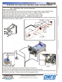
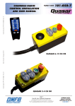
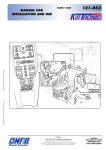
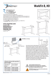
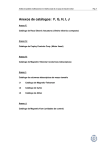
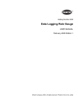
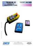
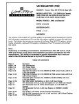
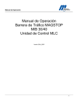
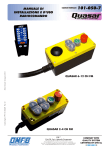
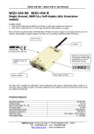
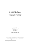
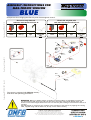
ASSEMBLY INSTRUCTIONS FOR
MAG-TRONIC VERSION
PTO CONTROL SYSTEM
BLUE
Codice fascicolo: 997-001-01131
Components for managing the PTO only with electromagnetic control.
Electric kit only PTO 12V
code 301-000-03124 inclusive of:
122-011-01650
100-002-00096
122-011-01865
Momentary
switch
Red cap
Indicator
light
306-001-01689
Electrical
wiring PTO
only
Electric kit only PTO 24V
code 301-000-03142 inclusive of:
122-011-02006
100-002-00096
122-011-01874
Momentary
switch
Red cap
Indicator
light
306-001-01689
Electrical
wiring PTO
only
Pink
Yellow
4
Gray
6
Orange
2
3
Red
Red
Data: Venerdì 12 luglio 2013
1
Red
Red
5
Red
Codice foglio:997-001-01097
Rev: AH
Black
The system is equipped with EEPROM memory
that stores the operating parameters.
WARNING: Before use battery charger or booster to vehicle’s battery it is mandatory to remove the
fuse 30A from the PTO electric loom kit. The lack of this procedure may lead to damage either the
electric kit or the PTO magnet. Restore the fuse in its seat only after making sure that vehicle switches on
regularly.
The body-builder is required to give evidence ot this procedure to the end user by applyng the warning
label, supplied along with the electric kit, directly on the vehicle’s battery
pag.13
O.M.F.B. S.p.A. Hydraulic Components
We reserve the right to make any changes without notice.
Edition 2007.04 No reproduction, however partial, is permitted.
Via Cave, 7/9 25050 Provaglio d’Iseo (Brescia) Italy Tel.: +39.030.9830611
Fax: +39.030.9839207-208 Internet:www.omfb.it e-mail:[email protected]
ASSEMBLY INSTRUCTIONS
E L E C T R ICAL D IAGR AM S
9ELLOW
04/ENGAGEMENT
CONTROL
1
2ED
2
/RANGE
3
%ARTH
1
Fuse
0INK
Codice fascicolo: 997-001-01131
/RANGE
$IAGNOSTICS
INDICATORLIGHT
'REY
$IAGNOSTICSINDICATORLIGHT
0INK
PTO ENGAGEMENT SWITCH DIAGRAM
&USE
!
/PTIONAL
CONSENT
04/STATUS
INDICATORLIGHT
&USE
!
04/ENGAGEMENT
CONTROL
WIRING DIAGRAM
2
Optional
consent
3
PTO engagement control
4
PTO status indicator light
5
Fuse 30A
6
Diagnostics indicator light (red key)
IMPORTANT: Incorrect connection of the two power cables, red and black,
will cause irreparable damage to the system.
In carrying out the assembly, scrupulously follow the order of the operations
as described in these instructions. This will minimise the possibility of making
assembly errors that could irreparably damage the system.
NEGATIVE battery pole
Connect the black wire marked “-Negative” to the negative
pole of the battery.
Do not use an earth on the frame, but only the negative battery pole.
POSITIVE battery pole
After making sure that the fuse is NOT fitted in its housing,
connect the red wire marked “+Positive” to the positive battery
pole.
pag.14
O.M.F.B. S.p.A. Hydraulic Components
We reserve the right to make any changes without notice.
Edition 2007.04 No reproduction, however partial, is permitted.
Via Cave, 7/9 25050 Provaglio d’Iseo (Brescia) Italy Tel.: +39.030.9830611
Fax: +39.030.9839207-208 Internet:www.omfb.it e-mail:[email protected]
Rev: AH
IMPORTANT: Electrical installations on vehicles and the connection of
external devices to the original system must be made by expert personnel,
under the absolute and sole responsibility of the person in charge of the
job.
Codice foglio:997-001-01097
Basic Configuration Assembly
Data: Venerdì 12 luglio 2013
301-0-03124/42: 2A
301-0-03160/88: 10A
ASSEMBLY INSTRUCTIONS
B A S I C CO N FIGUR ATIO N
SECTION REGARDING THE WIRING OF THE PTO ONLY
FOR SYSTEMS WITH DUMPING SECTION, SEE PAGE 20
Codice fascicolo: 997-001-01131
Engagement device:
The kit includes as standard supply a momentary switch for PTO engagement. In any case, MAG-TRONIC automatically recognises whether the PTO engagement control is “interlocking” or “momentary”
type. Specifically, if the PTO engagement control signal remains active for more than 10 seconds, it is
recognised as interlocking; when it is released the PTO is disengaged. On the other hand, if the PTO engagement control returns to 0 within 3 seconds, it is recognised as momentary; activating it again causes
immediate disengagement of the PTO.
Pink
Gray
ow
ll
Ye
1 PINK
2 RED
Orange
Red
3 ORANGE
d
Re
d
Re
In the BASIC configuration,
the red wire and the grey wire
must be interconnected.
Re
d
Data: Venerdì 12 luglio 2013
Wiring sequence:
1) Connect the pink wire of the wiring harness to position 1 of the engagement switch.
2) Connect one of the two red wires to position 2 of the engagement switch.
3) Connect the orange wire to position 3 of the engagement switch.
4) Connect the second red wire to one of the two ends of the indicator light.
5) Connect the yellow wire to the other end of the indicator light.
6) Connect the grey wire to the red wire with male ending (if you want to set up using enable signal, refer to
the concerning appendix);
7) Connect the free red wire of the positive controls’ lead to a positive subkey on the vehicle’s original system.
To use the “PTO Engaged” signal differently from the simple driving of the standard indicator light,
refer to the specific section of the instructions (page 14).
Codice foglio:997-001-01097
Rev: AH
Warning:
Preferably use a positive subkey for power feed to the control/consent buttons.
To guarantee that the PTO cannot be left engaged unintentionally for excessively long periods of time,
the standard version implements a function that automatically disengages it after 6 consecutive hours
of engagement. To obtain the automatic disengagement in correspondence with vehicle switch-off with
the ignition key, it is necessary to pick up the control positive from a key positive and create one of the
configurations shown in the table below:
Engagement
control type
Momentary
Interlocking
Interlocking
Consent
control type
Control
positive pickup
Automatic disengagement
upon removing the ignition key
Interlocking
Key positive
Yes
Momentary
Key positive
Yes
If the control positive pickup is a direct battery positive, the system does not disengage the PTO in correspondence with vehicle switch-off with the ignition key. Moreover, independently of the type of positive
used, if both engagement and consent controls are momentary type, the system does not disengage the
PTO in correspondence with vehicle switch-off with the ignition key.
pag.15
O.M.F.B. S.p.A. Hydraulic Components
We reserve the right to make any changes without notice.
Edition 2007.04 No reproduction, however partial, is permitted.
Via Cave, 7/9 25050 Provaglio d’Iseo (Brescia) Italy Tel.: +39.030.9830611
Fax: +39.030.9839207-208 Internet:www.omfb.it e-mail:[email protected]
ASSEMBLY INSTRUCTIONS
NO
After checking again to make sure that you
have correctly connected the “ + Positive” cable to the battery positive and the
“ - Negative” cable to the battery negative, open the fuse-holder cover, insert
the 30A fuse, and re-close the cover.
ENGAGED PTO INDICATOR: ALTERNATIVE USES
The system indicates the current engage/disengage condition of the PTO engage indicator light.
The electrical signal provided can control a maximum power load of 250 mA: excess power load
can change and cause irreparable damage to the output stage and therefore to the system itself. A configuration such as the one in the diagram, must be employed for any alternative uses
to controlling the indicator light supplied in the standard kit (such as enabling PLC systems for
aerial platforms, NU equipment or other). The illustrated configuration entails controlling a relay
with a recirculation diode assembled on the reel of the same. Any use other than control of the
indicator light must therefore involve assembly of an accessory relay not controlled directly by
PTO signal on the OMFB system.
9ELLOW
9ELLOW
pag.16
O.M.F.B. S.p.A. Hydraulic Components
We reserve the right to make any changes without notice.
Edition 2007.04 No reproduction, however partial, is permitted.
Via Cave, 7/9 25050 Provaglio d’Iseo (Brescia) Italy Tel.: +39.030.9830611
Fax: +39.030.9839207-208 Internet:www.omfb.it e-mail:[email protected]
Data: Venerdì 12 luglio 2013
YES
Once the connection is made, clip it to the
frame horizontally to prevent accumulations of stagnant water.
Rev: AH
Make sure that the connectors are
thoroughly connected up to the click
of the limit stop.
Codice foglio:997-001-01097
Connect the wiring harness to the MAGTRONIC using the 7-way connector.
Codice fascicolo: 997-001-01131
The person fitting the system is the sole one responsible for applying all necessary measures for minimising risks of involuntary activation by the operator. OMFB therefore recommends protecting the positive
side of the control buttons with a dedicated key.
In any case, configuration with door enablement per se considerably reduces the risk of involuntary activation.
OMFB recommends that the diagnosis indicator always be connected. This indicator can be highly useful
in the event of malfunction or failure, as it immediately reveals the type of problem and cause, for resolution. This indicator provides the operator with information on the current condition of system operation.
ASSEMBLY INSTRUCTIONS
VAR I AN T S O F BASE CO N FIGUR ATIO N
Codice fascicolo: 997-001-01131
CONFIGURATIONS WITH CONSENT/INTERLOCK INDICATOR
OMFB highly recommends using configurations with the consent/interlock indicator, for safety
reasons and for allowing the mechanical organs to always work in optimal conditions.
System accessories allowing use of configurations with consent/interlock indicators should be
assembled according to both electrical and mechanical state-of-the-art: poor system assembly
can result in malfunction.
MAG-TRONIC automatically recognises whether the consent signal is “interlocking” or “momentary” type. Specifically, if the PTO engagement control signal remains active for more than 10
seconds, it is recognised as interlocking; when it is released the PTO is disengaged. On the other
hand, if the PTO engagement control returns to 0 within 3 seconds, it is recognised as momentary; activating it again causes immediate disengagement of the PTO.
MOMENTARY CONSENT:
The engagement of the PTO is subordinate to the consent applied for a period less than 5 seconds (e.g.: switching of a switch on the clutch pedal). With the PTO engaged, the momentary
activation of the consent (e.g.: pressing the clutch pedal) causes immediate disengagement of
the PTO.
INTERLOCKING CONSENT:
The engagement of the PTO is subordinate to the consent maintained for a period of more than
10 seconds (e.g.: switching of a switch on the hand brake). With PTO engaged, the disactivation
of the consent (e.g.: release of the hand brake) causes immediate disengagement of the PTO.
Yellow
Pink
Codice foglio:997-001-01097
Rev: AH
Data: Venerdì 12 luglio 2013
Gray
Gray
Brown
Orange
Red
Red
Red
These configurations, whether interlocking or momentary, are obtained by connecting a NO
switch between the red wire and the grey wire of the standard wiring harness, using the malefemale faston connectors normally connected together.
N.B.: After making sure that the mechanical and electrical assembly of the switch has been
carried out correctly, is suitably adjusted, and guarantees the necessary reliability, perform a
number of test cycles.
The OMFB catalogue includes the clutch switch kit for the main types of vehicles, composed of
attachment brackets, screws, momentary switch, and connection cables.
pag.17
O.M.F.B. S.p.A. Hydraulic Components
We reserve the right to make any changes without notice.
Edition 2007.04 No reproduction, however partial, is permitted.
Via Cave, 7/9 25050 Provaglio d’Iseo (Brescia) Italy Tel.: +39.030.9830611
Fax: +39.030.9839207-208 Internet:www.omfb.it e-mail:[email protected]
ASSEMBLY INSTRUCTIONS
U S E R M AN UAL
INTRODUCTORY NOTES:
The use of and engagement of PTO requires that the operator knows exactly what he is doing and how
the system runs. It is sol responsibility of preparer/agent to provide instruction on how the system works
and of its risks from such use.
Engaging the PTO shall be performed when vehicle is not in motion idling engine and with the contextual
pressure of the clutch pedal. Not using the breaks during engagement could cause not only lack of engagement but also damage to the power take-off and vehicle gears.
When the configuration requires a consent signal engagement shall not be performed until the signal is
present (for example pressing the breaks, engaging the hand break, other signals from PLC or control
system).
The existence of a consent signal on the clutch means that the technical operation times of the clutch itself
are respected:
• During the engagement phase, releasing the clutch more than 10 seconds after its activation will lead
to the disengagement of the PTO as it is interpreted as stable consent.
• The engagement of the PTO can only take place after at least 5 seconds have passed from the last
disengagement by means of the use of the clutch.
Codice fascicolo: 997-001-01131
CONDITIONS OF USE:
Configurations which require a consent/interlock signal, this must be activated before giving pressure to
the engage button.
-Press the clutch pedal and keep it down
-Press and release the engage button
-Within one and a half seconds the PTO is activated
-The PTO is effectively engaged when the system signals fixed ignition through the PTO engaged light
-Release the clutch pedal
-If the system is not able to complete the engagement procedure on the first attempt, the diagnostics
indicator light will light up momentarily and two more attempts will be made automatically.
-If the engagement is accomplished normally, the diagnostics indicator light goes off and the light indicating PTO engaged stays on stably.
-If the two subsequent attempts made by the system in automatic are not successful, both the PTO engaged indicator light and the diagnostics indicator light flash until the subsequent engagement command.
-If the PTO is not engaged following a complete cycle of three attempts, repeat the procedure from the
beginning, paying careful attention to follow all the instructions as given.
-If the PTO has not engaged after three complete cycles, contact the vehicle manufacturer or the OMFB
technical service.
Data: Venerdì 12 luglio 2013
ENGAGE PTO:
INTERNAL DIAGNOSIS AND SIGNALS:
The system monitors fundamental parameters: temperature, power tension, solenoid continuity, solenoid
current.
When PTO is disengaged and one of these parameters do not fall within the prescribed range and the
system does not allow PTO engagement, signalling the cause with a combination of PTO engage lights
and diagnosis (see table page 19).
When PTO is engaged and one of these parameters fall out of range (high or low) the system disengages
the PTO and signals the cause with a combination of PTO engage lights and diagnosis.
MANUAL EMERGENCY ENGAGEMENT:
In the event of a malfunction of MAG-TRONIC, the PTO can be engaged manually (see specific instructions provided with the PTO and the emergency screw).
pag.18
O.M.F.B. S.p.A. Hydraulic Components
We reserve the right to make any changes without notice.
Edition 2007.04 No reproduction, however partial, is permitted.
Via Cave, 7/9 25050 Provaglio d’Iseo (Brescia) Italy Tel.: +39.030.9830611
Fax: +39.030.9839207-208 Internet:www.omfb.it e-mail:[email protected]
Codice foglio:997-001-01097
Configurations which require a consent/interlock signal will automatically disengage the PTO if it does
not occur.
-Press the clutch pedal and keep it down
-Press and release the engage button
-The PTO is deactivated
-The PTO is effectively disengages when the system signals fixed ignition PTO engage light goes off
-Release the clutch pedal
Rev: AH
DISENGAGE PTO:
ASSEMBLY INSTRUCTIONS
A L A R M D IAGN O STICS TABLE
PTO indicator light
(red cap)
Diagnostics indicator light
(red key) engage PTO
Flashing
Flashing
Off
Flashing
Fixed
Flashing
Off
Fixed
Flashing as long as the engagement switch is pressed
Off
Codice fascicolo: 997-001-01131
Type of alarm
Gear locking
Spontaneouss Disengagement
Overtemperature
Power supply voltage
below threshold
No consent
ELECTRIC SPECIFICATIONS
PARAMETER
Tension supply
Codice foglio:997-001-01097
Rev: AH
Data: Venerdì 12 luglio 2013
Average engage
current
Steady current
VALUE
NOTES
min. typical max.
Proper functioning value. Under minimum value the
card does not supply the solenoid. Above the maxi10 V
30 V
mum value the card can break. Never exceed maximum value.
This current value is maintained only for the first 2
57.0 A
seconds form pressing the connection button.
This current value is maintained while PTO is con2.5 A
nected
Stand-by current
45 mA
Output current
signal line PTO
engaged
Output current
signal line alarm
Input current PTO
engaged
Input current
sonsent/interlock
250
mA
Superior current values can cause momentary malfunctions of definitive damage to system
250
mA
Superior current can cause momentary malfunctions
of definitive damage to system
3 mA
3 mA
ENVIRONMENTAL SPECIFICATIONS
Work temperature -40°C
Storage
temperature
-40°C
85°C
85°C
pag.19
O.M.F.B. S.p.A. Hydraulic Components
We reserve the right to make any changes without notice.
Edition 2007.04 No reproduction, however partial, is permitted.
Via Cave, 7/9 25050 Provaglio d’Iseo (Brescia) Italy Tel.: +39.030.9830611
Fax: +39.030.9839207-208 Internet:www.omfb.it e-mail:[email protected]
ASSEMBLY INSTRUCTIONS
E LE C TR I C K I T FO R P T O CO N TR O L AN D TIPPIN G VALVE
PTO + Tipping valve 12V code: 301-000-03160
PTO + Tipping valve 24V code: 301-000-03188
Cabin wiring harness:
1) Connect one of the three red wires to one of the two ends of the orange indicator light.
2) Connect the other two red wires to the “D” and “L” contacts of the rocker switch.
3) Connect the yellow/black wire to the other end of the indicator light.
4) Connect the green wire (lower) to the “ “ contact of the rocker switch.
5) Connect the blue wire (raise) to the “H” contact of the rocker switch.
6)Connect the free red wire of the positive controls’ lead to a positive subkey on the vehicle’s original system.
7)Connect the brown cable to earth
Yellow/Black
Green
Blue
Red
Pink
Red
“T”
Yellow
Red
“L”
“”
“H”
“D”
“U”
Codice fascicolo: 997-001-01131
Electric kit
Red
Red
Red
Red
Data: Venerdì 12 luglio 2013
Brown
1
2
Yellow/black (-)
Yellow/black
Brown
Frame wiring harness:
1) Connect the yellow/black and brown wires to the contacts of the pressure switch.
2) Connect the red wire to the positive contact of the buzzer.
3) Connect the yellow/black wires to the negative contact of the buzzer.
4) Connect connector 2 (raise) to the coil on the side of the maximum pressure valve of the FE40 switch.
5) Connect connector 1 (lower) to the coil on the opposite side.
pag.20
O.M.F.B. S.p.A. Hydraulic Components
We reserve the right to make any changes without notice.
Edition 2007.04 No reproduction, however partial, is permitted.
Via Cave, 7/9 25050 Provaglio d’Iseo (Brescia) Italy Tel.: +39.030.9830611
Fax: +39.030.9839207-208 Internet:www.omfb.it e-mail:[email protected]
Codice foglio:997-001-01097
Rev: AH
Red (+)
ASSEMBLY INSTRUCTIONS
Codice fascicolo: 997-001-01131
Product Markings and certification
The MAG-TRONIC elettromagnetic system complies with the essential requirements
and other pertinent provisions set forth in European Directive 2006/28/EC and in
ECE/ONU Regulation No 10 Addendum 2, relating to “Suppression of radio interference
(Electromagnetic Compatibility) produced by spark-ignition engines fitted to motor
vehicles”.
Concerning to Electromagnetic Compatibility 2006/28/EC is the reference directive for
every electrical/electronic system included in road vehicles because it constitutes a “specific
directive” for the purposes of Article 2, par. 2, of Council Directive 89/336/EC, effective
beginning 1 January 1996.
The provisions of 2006/28/EC must be satisfied, concerning Electromagnetic Compatibility,
by all vehicles as defined in Directive 70/156/EC relating to the type-approval of motor
vehicles and their trailers, as emended by 98/14/EC, as well as their components or
separate technical units that are exempt from the compliance with the rules of 89/336/
EC.
Data: Venerdì 12 luglio 2013
Conformity tests prescribed by Directive 2006/28/CE and ECE/ONU Reg. No 10 Add. 2
were carried out at the laboratory PRIMA RICERCA & SVILUPPO (via Campagna, 58 22020 Gaggino Faloppio (CO)).
Compliance of MAG-TRONIC electromagnetic system with Dir. 2006/28/EC requirements
is certified by the Notified Body NSAI (National Standards Authority of Ireland-Glasnevin,
Dublin 9, Ireland (+353-1-80703910)) by releasing the approval number for the product
marking:
e24*72/245*2006/28*1406.
Compliance is shown by product marking:
Codice foglio:997-001-01097
Rev: AH
e24
031406
Compliance of MAG-TRONIC electromagnetic system with the ECE/ONU Reg. No 10
Add. 2 requirements is certified by the Notified Body NSAI (National Standards Authority
of Ireland-Glasnevin, Dublin 9, Ireland (+353-1-80703910)) by releasing the approval
number for the product marking:
E24 10R-020311.
Compliance is shown by product marking:
E24
10R
02 0311
pag.21
O.M.F.B. S.p.A. Hydraulic Components
We reserve the right to make any changes without notice.
Edition 2007.04 No reproduction, however partial, is permitted.
Via Cave, 7/9 25050 Provaglio d’Iseo (Brescia) Italy Tel.: +39.030.9830611
Fax: +39.030.9839207-208 Internet:www.omfb.it e-mail:[email protected]