1
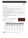
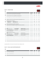
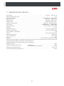
D163H002 Ed.04 GB
Temperature controllers
User Manual
Contents
Page
Chapter 1: Introduction . . . . . . . . . . . . . . . . . . . . . . . . . . . . . . . . . . . . . . . . . . . . . . . . . . . . . . . . . . 3
Chapter 2: Description . . . . . . . . . . . . . . . . . . . . . . . . . . . . . . . . . . . . . . . . . . . . . . . . . . . . . . . . . . . 4
2.1 Keypad functions . . . . . . . . . . . . . . . . . . . . . . . . . . . . . . . . . . . . . . . . . . . . . . . . . . . . . . . . 4
2.2 Display messages . . . . . . . . . . . . . . . . . . . . . . . . . . . . . . . . . . . . . . . . . . . . . . . . . . . . . . . . 5
2.3 Maintenance . . . . . . . . . . . . . . . . . . . . . . . . . . . . . . . . . . . . . . . . . . . . . . . . . . . . . . . . . . . 6
2.4 Precautions . . . . . . . . . . . . . . . . . . . . . . . . . . . . . . . . . . . . . . . . . . . . . . . . . . . . . . . . . . . . 6
Chapter 3: Initial Setup . . . . . . . . . . . . . . . . . . . . . . . . . . . . . . . . . . . . . . . . . . . . . . . . . . . . . . . . . . 6
3.1 Wizard . . . . . . . . . . . . . . . . . . . . . . . . . . . . . . . . . . . . . . . . . . . . . . . . . . . . . . . . . . . . . . . . 6
3.2 Basic settings . . . . . . . . . . . . . . . . . . . . . . . . . . . . . . . . . . . . . . . . . . . . . . . . . . . . . . . . . . . 7
Chapter 4: Operation . . . . . . . . . . . . . . . . . . . . . . . . . . . . . . . . . . . . . . . . . . . . . . . . . . . . . . . . . . . . 8
4.1 Compressor control . . . . . . . . . . . . . . . . . . . . . . . . . . . . . . . . . . . . . . . . . . . . . . . . . . . . . . 8
4.2 Defrost control . . . . . . . . . . . . . . . . . . . . . . . . . . . . . . . . . . . . . . . . . . . . . . . . . . . . . . . . . 10
4.3 Fan control . . . . . . . . . . . . . . . . . . . . . . . . . . . . . . . . . . . . . . . . . . . . . . . . . . . . . . . . . . . . 13
4.4 Light control. . . . . . . . . . . . . . . . . . . . . . . . . . . . . . . . . . . . . . . . . . . . . . . . . . . . . . . . . . . 13
4.5 Alarms . . . . . . . . . . . . . . . . . . . . . . . . . . . . . . . . . . . . . . . . . . . . . . . . . . . . . . . . . . . . . . . 14
Chapter 5: Wiring. . . . . . . . . . . . . . . . . . . . . . . . . . . . . . . . . . . . . . . . . . . . . . . . . . . . . . . . . . . . . . 15
Chapter 6: Parameter setup . . . . . . . . . . . . . . . . . . . . . . . . . . . . . . . . . . . . . . . . . . . . . . . . . . . . . . 16
6.1 Programming Menu . . . . . . . . . . . . . . . . . . . . . . . . . . . . . . . . . . . . . . . . . . . . . . . . . . . . . 16
6.1.1 Changing the operating parameters . . . . . . . . . . . . . . . . . . . . . . . . . . . . . . . . 16
6.1.2 Parameters. . . . . . . . . . . . . . . . . . . . . . . . . . . . . . . . . . . . . . . . . . . . . . . . . . . 17
Chapter 7. Technical Specifications . . . . . . . . . . . . . . . . . . . . . . . . . . . . . . . . . . . . . . . . . . . . . . . . . 21
AKO Electromecanica thanks and congratulates you for purchasing our product, in whose development and manufacture the most
innovative technology has been used, as well as strict production and quality control processes.
Our commitment to satisfy our customers and our continuous efforts to improve every day can be seen in the various quality certifications we have obtained.
This is a high performance, high technology product. The operation and final performance of the equipment depend on proper planning, installation, configuration and commissioning. Read this manual carefully before installation, and always follow its instructions.
Only qualified personnel should install or perform technical assistance on this product.
This product is designed to be used in the applications described in the product manual. AKO Electromecánica gives no guarantee
of its operation in any use not foreseen in the manual, and is not responsible for any damage resulting from improper use, configuration, installation or commissioning.
It is the responsibility of the installer and the customer to comply with and ensure others comply with all regulations applicable to
installations incorporating our products. AKO Electromecánica is not responsible for any damage caused by non-compliance with regulations. Follow strictly the instructions given in this manual.
To maximise the service life of our equipment, these recommendations should be followed:
Do not expose electronic equipment to dust, dirt, water, rain, humidity, high temperatures, chemicals or corrosive substances of any sort.
Do not submit the equipment to blows or vibrations nor try to manipulate it differently from shown in the manual.
Never exceed the specifications and limitations indicated in the manual.
Always respect the specified ambient working and storage conditions.
During and after installation, avoid leaving loose, broken, unprotected or damaged wiring, since they might constitute
a risk for the equipment and its users.
AKO Electromecánica reserves the right to make any non-metrology modification to the documentation or the equipment without
previous notice.
2
1.- Introduction
The Darwin controller range is particularly suitable for controlling refrigerating equipment, wall units, islands, cabinets, electrical panels, etc.
The wide range of models available ensures the best solution for each application.
The AKO-16323 model has been specially designed for applications requiring a large number of output relays and
high power switching.
The information displayed on the 2.3" high brightness display can be seen from any angle and from farther away
than conventional controllers.
New features have been added which allow more efficient refrigeration management, thus saving energy.
The menu settings are optimized for fast and intuitive programming and may be pre-programmed according to the
application for faster start-up.
Application
It has three relays and is designed for above- and below-freezing applications, with defrost by resistors or cycle
reversal.
3
2.- Description
FAN relay active
COOL relay active
DEF relay active
Alarm active
Display
UP key (N)/SET
DOWN key (Q)
Terminal blocks
Flashing lights indicate that the function in question should be activated by temperature, but is not due to a conflicting
timing or protection parameter.
2.1.- Keypad functions
Press for 5 seconds to activate Standby mode; press for 2 seconds to return the equipment to normal mode. In
Standby mode, the equipment performs no actions and only the AKO indicator is displayed on the screen.
Press for 10 seconds to go to the programming menu.
Press for 5 seconds in the programming menu to access the level displayed on the screen or, during the setting of a
parameter, accepts the new value.
In the programming menu, a short press allows you to scroll through the various levels or, during the setting of a parameter, to
increment the value. When upper limit is reached, it will start again from the lower limit.
Press for 5 seconds to start Fast Freezing mode.
In the programming menu, a short press allows you to scroll through the various levels or, during the setting of a
parameter, to increment the value.
IMPORTANT: If you have configured the access code function as a key lock (P2=2) when you initiate any function
(defrost or access to programming) you will be prompted to enter the access code programmed into L5. If the code
entered is not correct, the unit will display the temperature without opening the requested function.
4
2.2.- Display messages
Flashing 0: Access code (Password) request. You must enter the access
code configured on L5 to execute the requested function (p. 8 y 16).
See also parameter P2 (p. 20)
Probe 1 or 2 faulty
(open circuit, crossover or temperature outside the probe limits; NTC: -50
to 99 ºC)
Indicates a defrost is underway. After defrosting, the message will continue to
be displayed during the time specified in parameter d3 (see Chapter 4.2).
Alternative with temperature:
Indicates continuous cycle or fast freezing cycle activation (see Section 4.1).
Alternative with temperature:
Maximum temperature in control probe alarm. Temperature set in A1 has
been reached (p. 14 and 15).
(activates alarm relay)
Alternative with temperature:
Minimum temperature in control probe alarm. Temperature set in A2 has
been reached (p. 14 and 15).
(activates alarm relay)
Alternative with temperature:
External alarm activated (by digital input) (p. 14 and 15).
(activates alarm relay)
Alternative with temperature:
Severe external alarm activated (by digital input) (p. 14).
(activates alarm relay)
Alternative with temperature:
Defrost alarm time-out. Displayed when a defrost ends after the maximum
time elapsed as defined in parameter d1. (p. 11 and 14).
(Does not activate alarm relay)
Alternative with temperature:
Door open alarm. Shown if the door remains open longer than specified in
parameter AC (p. 14 and 15).
(No activa relé de alarma)
Alternative with temperature:
ECO mode active
5
2.3.- Maintenance
Clean the surface of the alarm using a soft cloth, soap and water. Do not use abrasive detergents, petrol, alcohol or
solvents.
2.5.- Precautions
Using the equipment without following the manufacturer's instructions may affect the device's safety requirements.
To ensure that the device operates correctly, only probes supplied by AKO should be used.
The unit must be installed in a location protected from vibrations, water and corrosive gases, where the ambient
temperature does not exceed that shown in the technical data.
To get a correct reading, the probe must be situated in a location without any external heat influences except for
the temperature which is being measured or controlled.
The probe and its cable should NEVER be installed in the same conduit as power, control or supply cables.
The power supply circuit must be provided with a main switch rated at least 2 A, 230 V, located close to the equipment.
The cables will enter through the back and should be type H05VV-F or H05V-K. The gauge will depend on local regulations, but should in no case be less than 1 mm².
The cables for connecting the relay contacts should be 1 to 2.5 mm² and the common cable should always be 2.5 mm².
Halogen-free cables are recommended.
Between -40 ºC and +20 ºC, if the NTC probe is extended up to 1,000 m with minimum 0.5 mm² wire, the maximum
deviation will be 0.25 ºC (Wire for probe extension ref. AKO-15586).
3.- Initial Setup
3.1.- Wizard
The Darwin range controllers have a setup wizard to configure the main
parameters for the type of application chosen (see table). The others will be
configured according to the "Def" column in the parameter table (see
section 6.1.2).
For the meaning of each parameter, see section 6.1.2.
This wizard only starts the first time the device is powered.
DEFAULT SETTINGS BY APPLICATION (In)
SP
d0
d1
F0
F3
P0
1
Multipurpose
2ºC
(36ºF)
4
20
8ºC
(46ºF)
1
0
2
Frozen
-18ºC
(-0,4ºF)
4
20
0ºC
(32ºF)
0
0
3
Fruits and
vegetables
10ºC
(50ºF)
4
20
30ºC
(86ºF)
1
0
4
Fresh fish
0ºC
(32ºF)
4
20
8ºC
(46ºF)
1
0
5
6
Soft Drinks Bottle Racks
3ºC
(37,4ºF)
24
20
8ºC
(46ºF)
1
0
12ºC
(53,6ºF)
24
20
30ºC
(86ºF)
1
0
7
AC
21ºC
(69,8ºF)
96
0
99ºC
(210ºF)
1
0
WARNING: The default parameters by type of application have been defined for the most common
applications. Check that these parameters are suitable for your installation.
6
3.2.- Basic settings
Type of inputs
The controller has 2 inputs for probes plus 2 digital inputs. The activation of the second probe is defined by
parameter P4:
P4=1: 1 probe input (S1: Control probe)
P4=2: 2 probe inputs (S1: Control probe y S2: Defrost probe).
Probe types
Parameter P9 permits selecting the type of probes to be connected between NTC (P9=0) and PTC (P9=1).
Probe function
S1: Temperature control probe, controls temperature of the chamber or cabinet (SP) acting on the COOL relay.
S2: Evaporator probe, controls the defrost end temperature (d4) and shuts down the fans (F0).
Probe to display
Parameter P8 defines which probe is displayed on the controller screen (P8=0 All probes sequentially, P8=1 Probe
1, P8=2 Probe 2)
In the sequential mode the screen will display the name of each probe followed by the temperature in each.
(S1 - 8,3ºC - S2 - 6,2ºC)
Calibrating probe 1
Allows correcting a possible error in probe reading. This can be very useful when you cannot place it in the ideal
place.
Display mode
Parameter P7 sets the display mode for the temperature displayed on the screen (P7=0 No decimals in ºC, P7=1
With a decimal in ºC, P7=2 No decimal degrees in ºF, P7=3, with a decimal in ºF).
The changes in this parameter do not affect the operation of the system because the controller automatically
calculates equivalent values for the set point, locks, alarms, calibration, etc.
Upper/lower blocking of the set point
Sets the upper (C2) and lower (C3) thresholds for the set point value (SP). These limits are also valid for automatic
variations of the set point (CA and CC).
Digital input function
The digital input function is defined by parameters PA (D1) and Pb (D2), with the following options:
PA/Pb=0:
PA/Pb=1:
PA/Pb=2:
PA/Pb=3:
PA/Pb=4:
PA/Pb=5:
PA/Pb=6:
PA/Pb=7:
PA/Pb=8:
PA/Pb=9:
Off (no function)
Door contact, controls the activation/deactivation of ECO mode. (p. 9)
External alarm, controls activation/deactivation of the external alarm (p. 14).
Severe external alarm, controls activation/deactivation of the severe external alarm (p. 14).
Slave defrost, activates defrost synchronisation with master uni (p. 11).
Activation of the ECO mode by pushbutton, controls activation/deactivation of the ECO mode using
an external pushbutton (p. 9).
Activation of the fast freezing mode, controls the activation/deactivation of this mode with an
external button (p. 8).
Not used
Defrost activation. You can control the activation/deactivation of the defrost using an external
pushbutton connected to the digital input.
Activation of the ECO mode by switch, controls activation/deactivation of the ECO mode using an
external switch (p.9).
7
gised, and displays a minute count. It is normal
single system during the process of start-up or
eated system start-ups when tests are carried o
Digital input polarity
Parameters PC (D1) and Pd (D2), define the polarity of the digital inputs, with the following options:
PC/Pd=0: The digital input is energised on closed contact.
PC/Pd=1: The digital input is energised on open contact.
ntroller will only show the temperature. It will n
(alarm, protection of the compressor, etc.) h
t by P1.
Password
Parameter L5 sets a 2-digit access code for accessing certain controller functions. Its functionality is set using the P2
parameter and a choice of several possibilities:
P2=0: Inactive access code; password will never by requested.
P2=1: Blocks access to parameters; will request access code (L5) when trying to access the program menu.
P2=2: Blocks keypad functions; will request the access code (L5) when trying to activate any of the keypad functions
(standby, defrost or program menu)
Power supply delays
Parameter P1 delays all controller functions when energised, and displays a minute count. It is normally used to
stagger the start-up of various refrigeration services in a single system during the process of start-up or reset after
a period without power. It can also help to avoid repeated system start-ups when tests are carried out on the
facility's electrical system.
IMPORTANT: During the time set in P1, the controller will only show the temperature. It will not control
the system in any way. If additional delays (alarm, protection of the compressor, etc.) have been
programmed, they start to run after the period set by P1.
4.- Operation
4.1.- Compressor control
NORMAL OPERATION (COOL)
When the temperature in probe 1 reaches the set
point value (SP) plus the probe differential (C1),
the COOL relay is activated, starting the
compressor and leading to a drop in temperature.
Once you the set point value (SP) is reached, the COOL relay is turned off,
stopping the compressor.
ON
COOL
OFF
ºC
SP
SP+C1
FAST FREEZING MODE
Commonly used for fast freezing newly stored product.
ON
COOL
OFF
SP-CA
ºC
SP
SP+C1
It is activated by an external switch (press once to
turn on or off), for which a digital input must be
configured as "fast freezing activation" (PA or
Pb = 6).
Upon enabling this mode, the compressor starts
up until the temperature of probe 1 reaches the set point value, plus the
change indicated in parameter CA.
Then the unit returns to normal operation.
If this point is not reached, the unit returns to normal operation after the
time set in C9.
8
ECO MODE
This mode saves energy during periods in which the refrigeration cabinet is not used
much. While this mode is active, the screen will display the message EC.
It is activated after a certain period (set in parameter Cb) of cabinet door inactivity, for
which one of the digital inputs must be set as "door contact" (PA or Pb = 1).
The operation is the same as normal, but increasing the set point by the
number of degrees set in parameter CC.
ON
COOL
OFF
ºC
SP+CC
(SP+CC)+C1
Otherwise, users may turn this function on and off at will by pressing an external button (1-touch on/off), for which
one of the digital inputs must be set as "ECO mode activation" (PA or Pb = 5).
Optionally, you can activate and deactivate this way whenever you want, using an external pushbutton (1 press to
activate/deactivate), or using a switch. To do so, one of the digital inputs such as “activation of the ECO mode by
pushbutton” (PA or Pb = 5) or “activation of the ECO mode by switch” (PA or Pb = 9) should be configured.
If parameter Cb is set to 0, the ECO mode will only activate via switch (PA or Pb=9).
COMPRESSOR PROTECTION DELAY
There are three types of delay, selectable by parameter C4, to protect the compressor (COOL relay). These delays
prevent continuous compressor starts and stops due to sudden changes in temperature.
OFF-ON (C4=0): Minimum compressor OFF time before each start-up.
OFF-ON / ON-OFF (C4=1): Minimum time during which the compressor will remain ON and OFF in every cycle.
The delay time is defined by parameter C5.
OPERATION IN CASE OF PROBE 1 FAILURE
OFF-ON (C4=0)
OFF-ON / ON-OFF (C4=1)
ON
ON
COOL
COOL
OFF
Time
SP
OFF
SP+C1
C5
SP
SP+C1
C5
Time
C5
In the event of probe 1 failure (fault, disconnection, etc.) compressor performance will depend on C6 settings.
Users may choose between 3 options:
C6=0: The compressor will be stopped until probe 1 is working again.
C6=1: The compressor will be operational until probe 1 is working again.
C6=2: The compressor will operate according to the average performance of the last 24 hours, taking into
account the number of starts and stops and the average time in each state (stop-start).
C6=3: The compressor will run as scheduled in C7 (ON) and C8 (OFF).
Probe 1 error (If C6=3)
ON
COOL
OFF
Time
9
C7
C8
C7
C8
4.2.- Defrost control
The auxiliary relay should be set to "defrost" (P6=1) (default setting), except in the
case of defrost by compressor shutdown.
default setting), except in the
Max. d1
F4
d3
FAN START DELAY
CONTROL
DEFROST
“dE" MESSAGE
DRIP TIME
CONTROL
DEFROST
d9
ºC
d0
d4
SP+C1
SP
time
Defrost start-up
Defrost is initiated if:
-Time scheduled in parameter d0 has passed since the beginning of last defrost.
-The DOWN (Q) key is pressed for 5 seconds.
Defrost type
Selected by parameter d7 to define the controller performance during the defrost process.
By compressor shutdown
(d7=3)
The compressor stops and the defrost takes place statically.
Fans will stop running regardless of parameter F3.
By air
(d7=2)
Fans start running and the compressor starts up. Defrost takes place by air being forced
through the evaporator.
Fans will be on regardless of parameter F3.
By resistors
(d7=0)
The defrost resistors start up and the compressor stops; defrost is the result of heat from the
resistors.
Fans will be running or not depending on parameter F3.
Reverse cycle
(Heatpump)
(d7=1)
A 4-way valve is activated which reverses the cold-generating circuit and the compressor starts
up, forcing the defrost.
Fans will be running or not depending on parameter F3.
By hot gas
(d7=1)
A valve is actuated which discharges gas from the compressor to the evaporator inlet. A check
valve prevents hot gas from returning to the liquid line.
Fans will be running or not depending on parameter F3.
Drip time
Parameter d9 sets drip time and the time added at the end of defrost cycle to allow for drainage of the remaining
water in the evaporator. During this time the compressor and fans will not be running (unless defrost is by air).
10
Defrost termination
The defrost will terminate if:
-The temperature programmed in parameter 24 has been reached in probe 2 (Requires an additional input for
the second probe and activates it via parameter P4).
-Time set in parameter d1 has passed (maximum duration of defrost).
-Press the DOWN (Q) key for 5 seconds.
Message displayed during defrost
Set by parameter d2, with the choice of showing the actual temperature detected by probe 1 (d2=0), displaying
the temperature detected by probe 1 at the start of defrost (d2=1) or displaying the dE message (d2=2). The d3
parameter defines the time during which the message is displayed, once the drip time (D9) and the fan stop time
(F4) is over.
Other parameters
Parameter d5 allows users to specify if the unit will (d5=1) or will not (d5=0) defrost when powered up (initial
start-up or after a power failure). In case of choosing option YES (d5=1), the defrost will start after the delay time
specified in d6.
Using parameter d8, users define the computation of time in d0, choosing between total time elapsed (d8=0) or
the total compressor running time (d8=1).
NOTE: If parameter d1 is set to 0, no defrost will be performed.
Remote defrost
Starts or stops the defrost using a pushbutton connected to one of the digital inputs. This input should be
configured for this function (PA or Pb=8).
Defrost Master - Slave
This feature allows users to synchronize defrost of several units. This is especially suitable for cabinets with multiple
independently controlled evaporators, thus avoiding having an evaporator defrosting (generating heat) while the
next is generating cold.
When the main controller configured as Master initiates a defrost, it forces the rest, which must be configured as
slaves (PA or Pb=4) to initiate their defrost cycles.
When the main controller ends the defrost according to the time set by d1 (the temperature in probe 2 is not taken
into account) it will force slaves to end defrosting and start synchronised drip time.
The master defrost function can only be set in controllers AKO-D14412, AKO-D14412-RC, AKO-D14423 and
AKO-D14423-RC and requires the use of an external relay (see diagram on next page).
Up to 15 units may be connected to a Master Controller and the maximum distance should not exceed 15 metres.
11
Example of Master - Slave defrost function
AKO-D144xx
1
2
3
AKO-D143xx
I max.:
16 A
L N
Master
I max.:
16 A
L N
Salve
4
5
6
7
8
9
10 11
1
2
3
4
5
6
7
8
9
10 11
DEF
DEF
S1
Settings:
d7=0 P4=2
P6=5
S1
S2
Settings:
d7=0 P4=2
P6=1 P10=4
RE
S2
AKO-D16323
1
2
3
4
16 A
6A
16 A
Slave
5
6
7
8
9
10 11 12 13
Settings:
d7=0 P4=2
P6=1 PA=4
S2
AKO-D16323
16 A
Slave
1
2
3
4
16 A
6A
Maximum distance 15 meters
S1
DEF
5
6
7
8
9
10 11 12 13
S1
Settings:
d7=0 P4=2
P6=1 PA=4
DEF
S2
S1: Control probe
S2: Defrost probe (evaporator)
RE: External relay
to other slave controllers
(Maximum 15 controllers)
12
4.3.- Fan control
Fan control
ON
COOL
OFF
ON
Only if F2=1
FAN
OFF
Time
F0
(probe 2)
F0+F1
(probe 2)
SP
SP+C1
The auxiliary relay must be configured as "Fans" (P6=0).
Fans are controlled with probe 2 (evaporator) and parameters F0 (shutdown temperature) and F1 (Probe differential).
Even if probe 2 is not connected (P4=1) or an error is detected in the probe (E2), the fans will always run
regardless of parameters F0 and F1, but taking into account parameters F2 to F5.
Parameter F2 defines the status of the fans during compressor stops and parameter F5 defines the status of the
fans when the door is opened, which requires setting up one of the digital inputs as door contact (PA or Pb=1).
If F5 = Yes, and the door remains opened more than 15 seconds, the compresor also stops.
Parameter F3 defines the status of fans during defrost. This feature is activated only for defrost by resistors, cycle
reversal or hot gas. If defrost is by air, the fans will always be active and if it is by compressor shutdown they will
always be inactive, regardless of parameter F3.
Parameter F4 defines the fan start-up delay after defrost (see section 4.2)
4.4.- Light control
On units with 2 or more relays, the auxiliary relay can be configured as "Light" (P6=3).
In these cases, the AUX relay will remain ON (lights on) while the unit is running. If the unit switches to standby
mode, the relay will switch OFF (lights out).
This feature turns off the lights in the cabinet when not in use (standby mode).
With parameter PJ, the status of the lights can be defined when the device is in ECO mode, except if this mode has
been externally activated by switch (PA or Pb=9), in which case, they will always stay on.
ers F0 (shutdown temperature) and F1 (Probe diffe
s detected in the probe (E2), the fans will alw
nt parameters F2 to F5.
ressor stops and parameter F5 defines the statu
13 door contact (PA or Pb
ne of the digital inputs as
ating1 areaches
relay* the
or both,
obe
valuewhen
set inthe programmed pa
erature) parameters.
4.5.- Alarms
The unit alerts users via a message on the screen, by activating a relay* or both, when the programmed parameter
criteria are met.
perature
at which
the alarm
obe 1 reaches
the value
set in
erature) parameters.
number of degrees above or
ch the alarm is activated. This
perature
at which
the having
alarm
t the set point
without
alarm settings.
number of degrees above or
ysteresis).
ch
the alarm is activated. This
t the set point without having
alarm settings.
Max/Min Temperature Alarm
Shows the AH or AL message when the temperature in probe 1 reaches the value set in
the A1 (AH: maximum temperature) and A2 (AL: low temperature) parameters.
This value can be:
Absolute (A0=1): A1/A2 should indicate the temperature at which the alarm
should be activated..
Relative to SP (A0=0): A1/A2 should indicate the number of degrees above or
below the set point at which the alarm is activated. This
option allows users to adjust the set point without having
to modify the high and low alarm settings.
Parameter AA sets the differentials for both parameters (hysteresis).
This alarm will also activate the auxiliary relay (if P6=2).
Example
In a controller we configure the following parameters: SP=2, A1=10, AA=2
- If A0=0 (relative to SP), the maximum temperature alarm goes off when probe 1 reaches 12 degrees and
is disabled when it reaches 10 degrees.
- If A0=1 (absolute), the maximum temperature alarm goes off when probe 1 reaches 10 degrees and is
disabled when it reaches 8 degrees.
External alarm/severe external alarm
Displays the message AE (external alarm) or AS (severe external alarm), when the digital
input configured as external alarm or severe external alarm is activated.
The severe external alarm also deactivates all the charges, therefore, the temperature
regulation is stopped. When this alarm disappears the device returns to its normal
operation.
At least one of the digital inputs must be configured as external alarm (PA or Pb=2) or
severe external alarm (PA or Pb=3).
This alarm will also activate the auxiliary relay (if P6=2).
Defrost alarm completed by time
Shows the Ad alarm message when a defrost terminates by time-out, if parameter
A8=1.
This alarm is only displayed on the screen; it will never activate the alarm relay.
ysteresis).
ers:
SP=2, A1=10, AA=2
ure alarm goes off when probe 1 reaches 12 deg
Alarma de puerta abierta
Displays PA message when the digital input configured as door contact (PA or Pb=1), is
active longer than the time set by parameter AC.
This alarm is only displayed on the screen; it will never activate the alarm relay.
alarm
goes A1=10,
off whenAA=2
probe 1 reaches 10 degree
ers: SP=2,
ure alarm goes off when probe 1 reaches 12 deg
*The AUX relay must be configured as an alarm (P6=2).
14
alarm
goes
off
when
probe
1 reaches 10 degree
xternal alarm), when the digital
Alarm delay
These delays prevent the display of specific alarms while allowing the unit to recover normal operation after certain
events.
-Start-up delays (A3): Delays activation of temperature alarms on power-up (start-up or after a power failure). This
allows avoiding continuous alarms upon start-up
-Delay after defrost (A4): Delays activation of temperature alarms post-defrost.
-Delay of max/min temperature alarm (A5): Delays activation of maximum (A1) and minimum (A2) temperature
alarms from the moment temperature probe 1 reaches the set value.
-Delay of external alarm / severe external alarm activation (A6): Delays the activation of the external alarm from
the moment the digital input becomes active.
-Delay of external alarm / severe external alarm deactivation (A7): Delays the deactivation of the external alarm
from the moment the digital input becomes inactive.
-Door opening alarm relay (AC): Delays activation of the open door opening detection alarm.
Alarm relay configuration
If the auxiliary relay is configured as an alarm relay (P6=2), parameter A9 allows defining the status of the relay when
an alarm is triggered.
A9=0 relay active (ON) in case of alarm (no alarm OFF); A9=1 Inactive relay (OFF) in case of alarm (no alarm ON)
5.- Wiring
I max.:
16 A
L N
6
7
8
9
10 11 12 13
S1
5
S2
4
DI1
3
DI2
2
90-240 V~
50/60 Hz
1
16 A
6A
16 A
AKO-D16323
FAN
AUX
AUX.
R. HEATER
AUX.
AUX
Operationg according to P6
S1: Probe 1, chamber or furniture temperature.
S2: Probe 2, defrost.
DI1/DI2: Digital input 1 / Digital input 2
COOL
15
6.- Parameter setup
Through the programming menu users can set different parameters to adjust the operation of the controller to the
needs of your installation.
6.1.- Programming Menu
To access the programming menu, press the UP/SET button for 10 seconds, or until the "PR" appears on the
screen.
IMPORTANT: If the access code function has been set as keypad lock (P2=2) or as parameter access
block (P2=1), when trying to access either of the two functions, users will be prompted to enter the access
code programmed in L5. If the code entered is not correct, the unit will revert to displaying the
temperature.
5 sec.
Temperature
Indication
Keep
pressed
UP/
SET
10 sec.
Release UP/SET
to go
to Stand-by
t
Release UP/SET
to access
programming
6.1.1.- Changing the operating parameters
Press the UP/SET button for 10 seconds or until "Pr" appears on the screen.
After 20 seconds with no key being pressed, the equipment will return to the previous level. If you are on level 3,
the changes will not be saved.
OUT OF
PROGRAMMING
PROGRAMMING
Level 1
Menus
Press
UP/
SET
>10 sec.
OK
Press
UP/
SET
>5 sec.
Level 2
Parameters
OK
Press
UP/
SET
>5 sec.
Change
Value
Press
UP/
SET
<5 sec.
Change
Parameters
Press
UP/
SET
<5 sec.
Change
Menu
Press
UP/
SET
<5 sec.
OK
Press
UP/
SET
>5 sec.
OK
Press
UP/
SET
>5 sec.
16
Level 3
Values
Save changes
Temperature
Indication
20 sec.
OK
Press
UP/
SET
>5 seg.
20 sec.
Don’t save changes
20 sec.
6.1.2.- Parameters
The unit's operation parameters are organized into groups or families according to their function.
The def. column shows factory-set default parameters. Those marked with an * are variable depending on the
application chosen in the wizard (see section 3.1). Temperature values are expressed in ºC. (Equivalent temperature
in ºF)
Level 2
Level 1.- Regulation and Control
Values
Min
Def
Max.
SP Temperature Adjustment (Set Point) (limits depending on probe type) (Page 8)
Description
(ºC/ºF)
-50
*
99
C0 Calibrating probe 1 (Offset) (Page 7)
(ºC/ºF)
-20
0.0
20
C1 Probe 1 differential (Histeresis) (Page 8)
(ºC/ºF)
0.1
2.0
20
C2 Upper blocking of the set point (Page 7) (cannot be set below this value)
(ºC/ºF)
C3
99
99
C3 Lower blocking of the set point (Page 7) (cannot be set below this value)
(ºC/ºF)
-50
-50
C2
0
0
1
0
0
99
0
2
3
Type of delay for protection of the compressor (relay COOL) (Page 9):
C4 0=OFF/ON (since the last disconnection);
1=OFF-ON/ON-OFF (since the last shut-down/start-up)
C5 Protection delay time (value od the option selected in parameter C4) (Page 9)
(min.)
Status of COOL relay with probe 1 fault (Page 9):
C6 0=OFF; 1=ON; 2=Average based on last 24 hours prior to probe fault;
3=ON-OFF as prog. C7 and C8
C7
Time relay ON in case of faulty probe (Page 9):
(If C7=0 and C8¹0, the relay will always be OFF deenergised)
(min.)
0
10
99
C8
Time relay OFF in case of fault of probe 1 (Page 9)
(If C8=0 and C7¹0, the relay will always be OFF deenergised)
(min.)
0
5
99
(h.)
0
24
48
(ºC/ºF)
0
-50
C3-SP
(h.)
0
2
24
(ºC/ºF)
0
2
C2-SP
C9 Maximum duration of fast freezing mode. (0=off) (Page 8)
Chagne set point (SP) in fast freezing mode, when it reaches this point (SP+CA),returns to
CA normal (Page 8)
(SP+CA ³ C3) (0=OFF) The vaule of this parameter is always negative, excepto if it is 0
Cb
Length of inactivity at digital input to activare ECO mode
(Only if PA or Pb =1) (0=OFF) (Page 9)
CC Change set point (SP) in ECO mode (SP+CC£ C2) (0= off) (Page 9)
EP Exit to Level 1
17
Level 2
Level 1.- Defrost Control
Values
(h.)
Min
Def
Max.
d0 Defrost frequency (Time between two starts) (Page 10)
0
96
d1 Maximum defrost duration (0=defrost deactivated) (Page 11)
(min.)
0
*
*
0
2
2
d2
Description
Type of message during defrost (Page 11)
0=Current temperature; 1=Temperature at start of defrost; 2=Display dE message
99
d3 Maximum duration of message (Page 11)
(min.)
0
5
99
d4 Defrost end temperature (Probe 2) (If P4 = 2) (Page 11)
(ºC/ºF)
-50
8
99,9
0
0
1
0
0
99
0
0
3
0
0
1
(min.)
0
1
99
d5
Defrost on equipment start-up (Page 11):
0=NO, First defrost as per d0; 1=YES, First defrost as per d6
d6 Defrost start delay on equipment start-up (Page 11)
Defrost type:
d7
(Page 10)
0=Resistors;
2=Fan/air;
(min.)
1=Reverse cycle
3= Compressor shutdown
d8
Calculated time between defrost period (Page 11):
0=Total actual time; 1 =Sum of times the compressor is on
d9
Drip time at end of defrsot (Page 10)
(compressor and fans off) (If P4 = 2)
EP Exit Level 1
Level 2
Level 1.- Fan Control
Values
Min
Def
Max.
F0 Fan shut-down temperature as per probe 2 (If P4 = 2) (Page 13)
Description
(ºC/ºF)
-50
*
99
F1 Probe 2 differencial (If P4 = 2) (Page 13)
(ºC/ºF)
0,1
2,0
20
F2 Stop fans when stopping compressor 0=No; 1=Yes (Page 13)
0
1
1
F3 Fan status during defrost (Page 13) 0=Off; 1=On
0
*
1
0
3
99
0
0
1
F4
Starting delay after defrost (If F3=0) (Page 13)
Will only operate if it is higher than d9
F5
Stops fans on opening the door 0=No; 1=Yes (Page 13)
(Requires a digital input configured as port PA or Pb=1)
(min.)
EP Exit Level 1
18
Level 2
Level 1.- Alarm control
Description
Values
A0 Configuration of temperature alarms (Page 14) 0=Relative to SP; 1=Absolute
Min
Def
0
0
Max.
1
A1 Maximum alarm probe 1 (must be greater then SP) (Page 14)
(ºC/ºF)
A2
99
99
A2 Minumum alarm probe 1 (must be greater then SP) (Page 14)
(min.)
-50
-50
A1
A3 Temperature alarm delay during start-up (Page 15)
(min.)
0
0
99
A4 Temperature alarm delay after completion of a defrost (Page 15)
(min.)
0
0
99
Temperature alarm delay after reaching the
A5
value of A1 or A2 (Page 15)
(min.)
0
30
99
A6
External alarm / severe external alarm delay when receiving digital input signal
(PA or Pb=2 or 3) (Page 15)
(min.)
0
0
99
A7
Deactivation delay of the external alarm / severe external alarm when the signal of
the digital input disappears (PA or Pb=2 or 3) (Page 15)
(min.)
0
0
99
A8 Show warning if defrost is terminated by time-out 0=No; 1=Yes (Page 14)
0
0
1
Alarm relay polarity
A9
(Page 15)
0
0
1
0= Relay ON in alarm (OFF no alarm);
1= Relay OFF on alarm (ON with no alarm)
AA Temperature Alarm Differential (A1 and A2) (Page 14)
(ºC/ºF)
0,1
1,0
20
AC Door open alarm delay (If PA or Pb = 1) (Page 15)
(min.)
0
2
99
EP Exit to Level 1
19
Level 2
Level 1.- General status
Description
Values
Min
Def
Max.
(min.)
0
0
99
0
0
2
P4 Selection of type of inputs: 1=1probe 2=2 probes (Page 7)
1
1
2
P5 MODBUS address (only systems with built-in communications)
1
1
99
P6 Configuration of AUX relay: 1=Defrost; 2=Alarm; 3=Light (Pages 10 to 15)
0
1
3
Temperature display mode (Page 7)
0= Whole in ºC
1=One decimal in ºC
P7
2=Whole in ºF
3=One decimal in ºF
0
1
3
0
1
2
0
0
1
P1 Daley of all functions on receiving electrical power (Page 8)
P2
P8
Access code (password) functions (Page 8)
0= Inactive; 1= Block access to parameters; 2= Keyboard lock
Probe to be displayed (as per parameter P4) (Page 7)
0=Visualization of all the probes in sequence; 1=Probe 1; 2=Probe 2
P9 Selection of probe type 0=NTC; 1=PTC (Page 7)
Configuring digital input 1 (Page 7)
0=Off
1=Door contact
4=Slave defrost
PA 3=Severe external alarm
6=Act. Fast Freezing (If C9 ¹0) 7=Not used
9=Act. ECO mode by switch
2=External Alarm
5=Act. ECO mode by pushbutton
8=Remote defrost
0
0
9
Configuring digital input 2 (Page 7)
0=Off
1=Door contact
4=Slave defrost
Pb 3=Severe external alarm
6=Act. Fast Freezing (If C9 ¹0) 7=Not used
9=Act. ECO mode by switch
2=External Alarm
5=Act. ECO mode by pushbutton
8=Remote defrost
0
0
9
PC Digital input polarity 1: 0=Energised on closed contact; 1=Energised on open contact (Page 7)
0
0
1
Pd Digital input polarity 2: 0=Energised on closed contact; 1=Energised on open contact (Page 7)
0
0
1
PJ Lights in ECO Mode (P6=3) 0=ON; 1=OFF (1)
0
0
1
Min
Def
Max.
0
-
99
EP Exit Level 1
(1): Without effect in the event of activation of the ECO mode by switch.
Level 2
Level 1.- Access control and information (ti)
Description
Values
L5 Access code (Password) (Pág.8)
PU Program version (Information)
-
Pr Program revision (Information)
EP Exit Level 1
-
20
7.- Especificaciones técnicas
Power supply . . . . . . . . . . . . . . . . . . . . . . . . . . . . . . . . . . . . . . . . . . . . . . . . . . . . . . . . . . . . . 90-240 V ~ 50/60 Hz 7 VA
Maximum Voltage SELV circuits . . . . . . . . . . . . . . . . . . . . . . . . . . . . . . . . . . . . . . . . . . . . . . . . . . . . . . . . . . . . . . . . . 20 V
nputs (According to P4) . . . . . . . . . . . . . . . . . . . . . . . . . . . . . . . . . . . . . . . . . . . . . . . . 2 inputs NTC/PTC + 2 digital inputs
Relay 16 A (COOL) . . . . . . . . . . . . . . . . . . . . . . . . . . . . . . . . . . . . . . . . . . . . . . . . . . . . . . . . (EN60730-1: 12(9) A 250 V~)
Relay 6 A (FAN) . . . . . . . . . . . . . . . . . . . . . . . . . . . . . . . . . . . . . . . . . . . . . . . . . . . . . . . . . . . (EN60730-1: 5(4) A 250 V~)
Relay 8 A (AUX) . . . . . . . . . . . . . . . . . . . . . . . . . . . . . . . . . . . . . . . . . . . . . . . . . . . . . . . . . . . (EN60730-1: 8(4) A 250 V~)
Number of relay operations . . . . . . . . . . . . . . . . . . . . . . . . . . . . . . . . . . . . . . . . . . . . . . . EN60730-1: 100.000 operations
Types of probe . . . . . . . . . . . . . . . . . . . . . . . . . . . . . . . . . . . . . . . . . . . . . . . . . . . . . NTC AKO-149xx / PTC AKO-1558xx
Measurement range . . . . . . . . . . . . . . . . . . . . . . . . . . . . . . . . . . . . . . . . . . . . . . . . . . . . . -50 ºC to +99 ºC (-58 ºF to 99 ºF)
Resolution . . . . . . . . . . . . . . . . . . . . . . . . . . . . . . . . . . . . . . . . . . . . . . . . . . . . . . . . . . . . . . . . . . . . . . . . . . . . . . . 0,1 ºC
Working environment . . . . . . . . . . . . . . . . . . . . . . . . . . . . . . . . . . . . . . . . . . . . . . . . . . . . . . -10 to55 ºC, humidity <90 %
Ambient storage humidity . . . . . . . . . . . . . . . . . . . . . . . . . . . . . . . . . . . . . . . . . . . . . . . . . . . -30 to 70 ºC, humidity <90 %
Class of protection - frontal panell . . . . . . . . . . . . . . . . . . . . . . . . . . . . . . . . . . . . . . . . . . . . . . . . . . . . . . . . . . . . . . . IP40
Fixation . . . . . . . . . . . . . . . . . . . . . . . . . . . . . . . . . . . . . . . . . . . . . . . . . . . . . . . . . . . . . . . . Panel-mounted with anchors
Panel cutout dimensions . . . . . . . . . . . . . . . . . . . . . . . . . . . . . . . . . . . . . . . . . . . . . . . . . . . . . . . . . . . . . . . . 124 x 85 mm
Front panel dimensions . . . . . . . . . . . . . . . . . . . . . . . . . . . . . . . . . . . . . . . . . . . . . . . . . . . . . . . . . . . . . . . . 139 X 100 mm
Depth . . . . . . . . . . . . . . . . . . . . . . . . . . . . . . . . . . . . . . . . . . . . . . . . . . . . . . . . . . . . . . . . . . . . . . . . . . . . . . . . . . 40 mm
Connections . . . . . . . . . . . . . . . . . . . . . . . . . . . . . . . . . . . . . . . . . . . . . . . . . . . . Screw terminals for cables up to 2.5 mm²
Rating of control device: built-in, automatic operation feature Type 1.B, for use in clean environments, Class A software and
continuous operation. Pollution classification 2 s/ UNE-EN 60730-1.
Double insulation between supply, secondary circuit and relay output.
Rated pulse voltage . . . . . . . . . . . . . . . . . . . . . . . . . . . . . . . . . . . . . . . . . . . . . . . . . . . . . . . . . . . . . . . . . . . . . . . . 2500 V
Temperature during ball-pressure test
Accessible parts . . . . . . . . . . . . . . . . . . . . . . . . . . . . . . . . . . . . . 75 ºC
Parts which position active elements . . . . . . . . . . . . . . . . . . . . . 125 ºC
Voltage and current as per EMC tests . . . . . . . . . . . . . . . . . . . . . . . . . . . . . . . . . . . . . . . . . . . . . . . . . . . . . . . . . 207 V, 17 mA
Current of radio jamming supression tests . . . . . . . . . . . . . . . . . . . . . . . . . . . . . . . . . . . . . . . . . . . . . . . . . . . . . . . 270 mA
21
22
23
Updated information on our website: www.ako.com
35D144002 REV.03 2014
AKO ELECTROMECÁNICA, S.A.L.
Av. Roquetes, 30-38 | 08812 Sant Pere de Ribes | Barcelona | España
Tel. (34) 938 142 700 | Fax (34) 938 934 054 | e-mail: [email protected] | www.ako.com