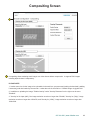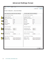
1
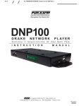
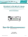
PEG-NE24-IP & PEG-NE24-IP-C Models
Public Educational & Governmental Access Encoder
INSTRUCTION MANUAL
Model
Item #
Description
PEG-NE24-IP
1002606
HD PEG Channel Encoder with HD-SDI Input and IP Output
PEG-NE24-IP-C 1002613
HD PEG Channel Encoder with HD-SDI or Composite Video Input
with L/R Audio and IP Output
937-746-4556
www.rldrake.com
© 2015 R.L. Drake Holdings, LLC.
Rev: 061915
We recommend that you write the following information in the spaces provided below.
Purchase Location Name:
Purchase Location Telephone Number:
PEG-NE24 Serial Number:
This product incorporates copyright protection technology that is protected by U.S. patents and other
intellectual property rights. Reverse engineering or disassembly is prohibited.
2
937.746.4556 | www.rldrake.com
Table of Contents
CAUTION STATEMENTS.......................................................................................................................................................... 4
IMPORTANT SAFETY INSTRUCTIONS.................................................................................................................................. 4
SPECIFICATIONS..................................................................................................................................................................... 6
INSTALLATION & POWER-UP................................................................................................................................................. 7
GENERAL DESCRIPTION & FEATURES................................................................................................................................ 8
FRONT AND REAR PANEL OPERATION............................................................................................................................... 9
LOGIN SCREEN....................................................................................................................................................................... 10
STATUS TAB.............................................................................................................................................................................11
ENCODER TAB........................................................................................................................................................................ 12
COMPOSITING SCREEN........................................................................................................................................................ 15
ADVANCED SETTINGS SCREEN........................................................................................................................................... 16
SYSTEM CONFIGURATION TAB............................................................................................................................................ 18
ADMIN SCREEN...................................................................................................................................................................... 20
FIRMWARE UPDATE TAB....................................................................................................................................................... 21
SERVICE................................................................................................................................................................................... 22
WARRANTY.............................................................................................................................................................................. 23
937.746.4556 | www.rldrake.com
3
REAR PANEL CONNECTIONS ..................................................................................................................................................................... 7
GENERAL DESCRIPTION .............................................................................................................................................................................. 6
ETHERNET ACCESS ....................................................................................................................................................................................... 8
FEATURES ........................................................................................................................................................................................................ 6
SETUP AND PROGRAMMING ................................................................................................................................................................... 10
INSTALLATION AND MOUNTING.............................................................................................................................................................. 6
FIRMWARE UPDATE .................................................................................................................................................................................... 15
REAR PANEL CONNECTIONS ..................................................................................................................................................................... 7
SERVICE / IF
YOU NEED
TO CALL FOR HELP ........................................................................................................................................ 188
ETHERNET
ACCESS
.......................................................................................................................................................................................
WARRANTY
..............................................................................................................................................................................................................
SETUP AND PROGRAMMING ...................................................................................................................................................................19
10
FIRMWARE
UPDATE
....................................................................................................................................................................................
15
Caution Statements:
SERVICE / IF YOU NEED TO CALL FOR HELP ........................................................................................................................................
18
A product and cart combination should be moved
with care.
WARRANTY ..............................................................................................................................................................................................................
19
WARNING: TO PREVENT FIRE OR ELECTRICAL
Quick stops, excessive force and uneven surfaces may
Caution Statements
SHOCK, DO
NOT EXPOSE TO RAIN OR MOISTURE.
Caution
Statements:
WARNING: TO PREVENT FIRE OR ELECTRICAL
SHOCK, DO NOT EXPOSE TO RAIN OR MOISTURE.
cause the product and cart combination to overturn.
A product
cart
combination
should be
moved
The
lightningand
flash
with
arrow head symbol,
within
an
with care.
equilateral
is force
intended
to alert surfaces
the usermay
to
Quick stops,triangle,
excessive
and uneven
the
of and
uninsulated
"dangerous
voltage"
causepresence
the product
cart combination
to overturn.
within
the product's
enclosure
may
be of
The lightning
flash with arrow
head that
symbol,
within
an
sufficient
constitute
risk the
of electric
equilateralmagnitude
triangle, istointended
to aalert
user to
shock
to persons.
the presence
of uninsulated "dangerous voltage"
The
exclamation
point within
an equilateral
within the product's
enclosure
that maytriangle
be of
is
intended
to
alert
the
user
to
presence
of
sufficient magnitude to constitute the
a risk
of electric
important
operating
and
maintenance
(servicing)
shock to persons.
instructions
in point
the literature
the
The exclamation
within an accompanying
equilateral triangle
product.
is intended to alert the user to the presence of
important operating and maintenance (servicing)
instructions in the literature accompanying the
product.
WARNING:
THE SOCKET-OUTLET SHALL BE INSTALLED NEAR THE EQUIPMENT AND SHALL BE EASILY ACCESSIBLE.
WARNING:
WARNING:
TO REDUCE THE RISK OF FIRE OR ELECTRIC SHOCK, DO NOT EXPOSE THIS PRODUCT TO RAIN OR
THE
SOCKET-OUTLET
SHALLTHE
BE INSTALLED
NEAR SERVICING
THE EQUIPMENT
AND SHALL
BE EASILYONLY.
ACCESSIBLE.
MOISTURE.
DO NOT OPEN
CABINET, REFER
TO QUALIFIED
PERSONNEL
WARNING:
CAUTION:
DO NOT EXPOSE
THIS PRODUCT
TO RAIN
OR
TO
RISK OF
FIRE OR
TO REDUCE
PREVENTTHE
ELECTRIC
SHOCK,
DOELECTRIC
NOT USESHOCK,
THIS (POLARIZED)
PLUG WITH
AN EXTENSION
CORD
MOISTURE.
DO
NOT
OPEN
THE
CABINET,
REFER
SERVICING
TO
QUALIFIED
PERSONNEL
ONLY.
RECEPTACLE OR OTHER OUTLET UNLESS THE BLADES CAN BE FULLY INSERTED TO PREVENT BLADE
EXPOSURE.
TO PREVENT ELECTRIC SHOCK, DO NOT USE THIS (POLARIZED) PLUG WITH AN EXTENSION CORD
RECEPTACLE OR OTHER OUTLET UNLESS THE BLADES CAN BE FULLY INSERTED TO PREVENT BLADE
ATTENTION: POUR PREVENIR LES CHOCS ELECTRIQUES, NE PAS UTILISER CETTE FICHE POLARISEE AVEC UN
EXPOSURE.
PROLONGATEUR, UNE PRISE DE COURANT OU UNE AUTRE SORTIE DE COURANT, SAUF SI LES LAMES
PEUVENT ETRE INSEREES A FOND SANS EN LAISSER AUCUNE PARTIE A DECOUVERT.
ATTENTION: POUR PREVENIR LES CHOCS ELECTRIQUES, NE PAS UTILISER CETTE FICHE POLARISEE AVEC UN
PROLONGATEUR, UNE PRISE DE COURANT OU UNE AUTRE SORTIE DE COURANT, SAUF SI LES LAMES
PEUVENT ETRE INSEREES A FOND SANS EN LAISSER AUCUNE PARTIE A DECOUVERT.
CAUTION:
Important Safety Instructions:
1.
2.
3.
1.4.
2.5.
3.6.
4.7.
5.
6.8.
7.
Important Safety Instructions
Read Instructions: All the safety and operating instructions should be read before the product is operated.
Retain Instructions: The safety and operating instructions should be retained for future reference.
Heed Warnings: All warnings on the product and in the operating instructions should be adhered to.
Read
Instructions:
AllAll
the
safety and
operating
instructions
should
be read before the product is operated.
Follow
Instructions:
operating
and
use instructions
should
be followed.
Retain
Instructions:
safetyfrom
and the
operating
instructions
should be
future
reference.
Cleaning:
Unplug thisThe
product
wall outlet
before cleaning.
Doretained
not use for
liquid
cleaners
or aerosol cleansers. Use a damp cloth for cleaning.
Heed
Warnings:
warnings
on the product
the operating by
instructions
should
be adhered
to. may cause hazards.
Attachments:
DoAll
not
use attachments
that areand
notinrecommended
the product
manufacturer
as they
Follow
AllDo
operating
instructions
should be followed.
Water Instructions:
and Moisture:
not useand
thisuse
product
near water—for
example, near a bathtub, wash bowl, kitchen sink or laundry tub; in a wet basement;
Cleaning:
Unplug this
product
from
or near a swimming
pool;
and the
like.the wall outlet before cleaning. Do not use liquid cleaners or aerosol cleansers. Use a damp cloth for cleaning.
Attachments:
attachments
that
recommended
by the
product
manufacturer
they
may cause
Accessories: Do
Donot
notuse
place
this product
onareannot
unstable
cart, stand,
tripod,
bracket,
or table. as
The
product
may hazards.
fall, causing serious injury to a child or
Water
andserious
Moisture:
Do to
notthe
useproduct.
this product
nearwith
water—for
near bracket,
a bathtub,
kitchen sink
tub; in DSE
aorwet
2basement;
PLUS
|3
adult, and
damage
Use only
a cart, example,
stand, tripod,
or wash
table bowl,
recommended
by or
thelaundry
manufacturer,
sold
with the
or near a swimming pool; and the like.
Instruction Manual
Accessories: Do not place this product on an unstable cart, stand, tripod, bracket, or table. The product may fall, causing serious injury to a child or
adult, and serious damage to the product. Use only with a cart, stand, tripod, bracket, or table recommended by the manufacturer, or sold with the
product. Any mounting of the product should follow the manufacturer's instructions, and should use a mounting accessory recommended by the
manufacturer.
A product and cart combination should be moved with care. Quick stops, excessive force, and uneven surfaces may cause the product and cart combination
to overturn.
Ventilation: Slots and openings in the cabinet are provided for ventilation and to ensure reliable operation of the product and to protect it from overheating,
and these openings must not be blocked or covered. The openings should never be blocked by placing the product on a bed, sofa, rug, or similar
surface. This product should not be placed in a built-in installation such as bookcase or rack unless proper ventilation is provided or the manufacturer's
instructions have been adhered to.
Power Sources: This product should be operated only from the type of power source indicated on the marking label. If you are not sure of the type of power
supplied to your home, consult your product dealer or local power company. For products intended to operate from battery power, or other sources, refer to the
product's operating instructions.
Grounding or Polarization: This product may be equipped with a polarized alternating-current line plug (a plug having one blade wider than the
other). This plug will fit into the power outlet only one way. This is a safety feature. If you are unable to insert the plug fully into the outlet, try reversing
the plug. If the plug should still fail to fit, contact your electrician to replace your obsolete outlet. Do not defeat the safety purpose of the polarized
plug. Alternate Warnings – If this product is equipped with a three-wire grounding- type plug, a plug having a third (grounding) pin, the plug will only fit
into a grounding-type power outlet. This is a safety feature. If you are unable to insert the plug into the outlet, contact your electrician to replace your
obsolete outlet. Do not defeat the safety purpose of the grounding-type plug.
Outdoor Antenna Grounding: If an outside antenna or cable system is connected to the product, be sure the antenna or cable system is
937.746.4556
| www.rldrake.com
grounded
so as to provide
some protection against voltage surges and built-up static charges. Article 810 of the National Electrical Code,
ANSI/NFPA 70, provides information with regard to proper grounding of the mast and supporting structure, grounding of the lead-in wire
Important Safety Instructions:
8.
9.
10.
11.
12.
413.
11. Power Sources: This product should be operated only from the type of power source indicated on the marking label. If you are not sure of the type of power
supplied to your home, consult your product dealer or local power company. For products intended to operate from battery power, or other sources, refer to the
product's operating instructions.
12. Grounding or Polarization: This product may be equipped with a polarized alternating-current line plug (a plug having one blade wider than the
other). This plug will fit into the power outlet only one way. This is a safety feature. If you are unable to insert the plug fully into the outlet, try reversing
the plug. If the plug should still fail to fit, contact your electrician to replace your obsolete outlet. Do not defeat the safety purpose of the polarized
plug. Alternate Warnings – If this product is equipped with a three-wire grounding- type plug, a plug having a third (grounding) pin, the plug will only fit
into a grounding-type power outlet. This is a safety feature. If you are unable to insert the plug into the outlet, contact your electrician to replace your
obsolete outlet. Do not defeat the safety purpose of the grounding-type plug.
13. Outdoor Antenna Grounding: If an outside antenna or cable system is connected to the product, be sure the antenna or cable system is
grounded so as to provide some protection against voltage surges and built-up static charges. Article 810 of the National Electrical Code,
ANSI/NFPA 70, provides information with regard to proper grounding of the mast and supporting structure, grounding of the lead-in wire
to an antenna discharge unit, size of grounding conductors, location of antenna-discharge unit, connection to grounding electrodes, and
requirements for the grounding electrode.
14. Power-Cord Protection: Power-supply cords should be routed so that they are not likely to be walked on or pinched by items placed upon or against them,
paying particular attention to cords at plugs, convenience receptacles, and the point where they exit from the product.
15. Lightning: For added protection for this product during a lightning storm, or when it is left unattended and unused for long periods of time, unplug it
from the wall outlet and disconnect the antenna or cable system. This will prevent damage to the product due to lightning and power-line surges.
16. Power Lines: An outside antenna system should not be located in the vicinity of overhead power lines, other electric light or power circuits, where it
can fall into such power lines or circuits. When installing an outside antenna system, extreme care should be taken to keep from touching such power
lines or circuits as contact with them may be fatal.
17. Overloading: Do not overload wall outlets, extension cords, or integral convenience receptacles as this can result in a risk of fire or electric shock.
18. Object and Liquid Entry: Never push objects of any kind into this product through openings as they may touch dangerous voltage points or short-out
parts that could result in a fire or electric shock. Never spill liquid of any kind on the product.
19. Servicing: Do not attempt to service this product yourself as opening or removing covers may expose you to dangerous voltage or other hazards.
Refer all servicing to qualified service personnel.
Safety Instructions continued...
20. Damage Requiring Service: Unplug this product from the wall outlet and refer servicing to qualified service personnel under the following conditions:
a) When the power-supply cord or plug is damaged,
b) If liquid has been spilled, or objects have fallen into the product,
c) If the product has been exposed to rain or water,
d) If the product does not operate normally by following the operating instructions.
Adjust only those controls that are covered by the operating instructions as an improper adjustment of other controls may result in damage and will
often require extensive work by a qualified technician to restore the product to its normal operation, e. If the product has been dropped or damaged
in any way, and f. When the product exhibits a distinct change in performance—this indicates a need for service.
21. Replacement Parts: When replacement parts are required, be sure the service technician has used replacement parts specified by the manufacturer
or have the same characteristics as the original part. Unauthorized substitutes may result in fire, electric shock or other hazards.
22. Safety Check: Upon completion of any service or repairs to this product, ask the service technician to perform safety checks to determine that the
product is in proper operating condition.
23. Wall or Ceiling Mounting: The product should be mounted to a wall or ceiling only as recommended by the manufacturer.
937.746.4556 | www.rldrake.com
5
Specifications
PEG-NE24-IP
Item # 1002606
PEG-NE24-IP-C
Item # 1002613
HD PEG Encoder with HD-SDI Input, and IP Output
HD PEG Encoder with HD-SDI or Composite Video with
L/R Audio Input, and IP Output
INTERFACE
INTERFACE
VIDEO INPUTS:
SD/HD-SDI BNC Type Input Connection
Closed Caption Support (embedded only)
AUDIO INPUTS:
SD/HD-SDI with PCM Embedded Audio
VIDEO OPTIONS
INPUT VIDEO MODES:
480i (640x480/720x480 @ 30FPS)
720p (1280x720 @ 60FPS)
1080i (1920x1080 @30FPS)
AUTO-SCAN for Input Resolution
VIDEO FORMAT:
MPEG-2 OR H.264
H.264 PROFILE SUPPORT:
Baseline, Main, High
AUDIO OPTIONS
ENCODER FORMAT:
Dolby® Digital, AAC or MPEG1-Layer 2
OUTPUT BITRATE:
128, 192, 320 or 384 Kbps
NOTE: 320kbps is an option for audio bitrate in MP2 and AAC only
Manufactured under license from Dolby Laboratories
OUTPUT
VIDEO OUTPUT:
PACKET FORMAT:
SFP Port IP SPTS (SFP module is required)
UDP SPTS (1xHD, 1xSD)
PHYSICAL SPECIFICATIONS
TEMPERATURE RATING:
FORM FACTOR:
DIMENSIONS:
WEIGHT:
POWER REQUIREMENTS:
0 - 50° C Ambient
Desktop Modulator
Approximately 7.5” D X 1.15” H X 3.5” W
1.15 lbs
110 VAC/60 Hz or 220 VAC/50 Hz
for supplied AC adapter
VIDEO INPUTS:
SD/HD-SDI BNC Type Input Connection
Composite Video RCA Input Connector
Closed Caption Support
AUDIO INPUTS:
SD/HD-SDI with PCM Embedded Audio
Analog Audio (L, R) 2xRCA Input Connectors
VIDEO OPTIONS
INPUT VIDEO MODES:
480i (640x480/720x480 @ 30FPS)
720p (1280x720 @ 60FPS)
1080i (1920x1080 @ 30FPS)
AUTO-SCAN for Input Resolution
VIDEO FORMAT:
MPEG-2 OR H.264
VIDEO ADJUSTMENTS:
H.264 PROFILE SUPPORT:
Brightness, Contrast, Hue, Saturation
Baseline, Main, High
AUDIO OPTIONS
ENCODER FORMAT:
Dolby® Digital, AAC or MPEG1-Layer 2
OUTPUT BITRATE:
128, 192, 320 or 384 Kbps
NOTE: 320kbps is an option for audio bitrate in MP2 and AAC only'
Manufactured under license from Dolby Laboratories
OUTPUT
VIDEO OUTPUT:
PACKET FORMAT:
SFP Port IP SPTS (SFP module is required)
UDP SPTS (1xHD, 1xSD)
PHYSICAL SPECIFICATIONS
TEMPERATURE RATING:
FORM FACTOR:
DIMENSIONS:
WEIGHT:
POWER REQUIREMENTS:
0 - 50° C Ambient
Desktop Modulator
Approximately 7.5” D X 1.15” H X 3.5” W
1.15 lbs
110VAC/60Hz or 220 VAC/50Hz
for supplied AC adapter
Optional SFP Plug-ins (1000 BT copper)
STOCK#
MODEL
DESCRIPTION
1002620
SFP-C-10/100/1000 TRANSCEIVER
10/100/1000BASE-T SFP, RJ-45, 100M, COPPER
1002621
SFP-MM-850-550M
1000BASE-SX SFP, 850NM, 550M, MMF, DDM
1002622
SFP-SMF-1310-10KM
1000BASE-LX SFP, 1310NM, 10KM, SMF, DDM
1002623
SFP-SMF-1550-80KM
1000BASE-ZX SFP, 1550NM, 80KM, SMF, DDM
1002624
SFP-SMF-CWDM-1470NM-80KM
1.25GBASE-CWDM-SFP, 1470NM, 80KM, SMF, DDM
1002625
SFP-SMF-CWDM-1490NM 80KM
1.25GBASE-CWDM-SFP, 1490NM, 80KM, SMF, DDM
1002626
SFP-SMF-CWDM-1510NM-80KM
1.25GBASE-CWDM-SFP, 1510NM, 80KM, SMF, DDM
1002627
SFP-SMF-CWDM-1530NM-80KM
1.25GBASE-CWDM-SFP, 1530NM, 80KM, SMF, DDM
1002628
SFP-SMF-CWDM-1550NM-80KM
1.25GBASE-CWDM-SFP, 1550NM, 80KM, SMF, DDM
1002629
SFP-SMF-CWDM-1570NM-80KM
1.25GBASE-CWDM-SFP, 1570NM, 80KM, SMF, DDM
1002630
SFP-SMF-CWDM-1590NM-80KM
1.25GBASE-CWDM-SFP, 1590NM, 80KM, SMF, DDM
1002631
SFP-SMF-CWDM-1610NM-80KM
1.25GBASE-CWDM-SFP, 1610NM, 80KM, SMF, DDM
1002632-XX
SFP-SMF-DWDM-CHXX-40KM
1.25GBASE-DWDM-SFP, CH. 20-59 ,40KM, SMF, DDM
1002633-XX
SFP-SMF-DWDM-CHXX-80KM
1.25GBASE-DWDM-SFP, CH. 20-59, 80KM, SMF, DDM
Last 2 numbers indicate channel number (20-59).
Specifications, price, and availability are subject to change without notice or obligation.
6
937.746.4556 | www.rldrake.com
..........................................................................................................................................
8
Rev: 20140���
......................................................................................................................................... 10
......................................................................................................................................... 15
Table of Contents
........................................................................................................................................
18
................................................................................................................................................ 19
.......................................................................................................................................... 2
Unpacking
..........................................................................................................................................
4
A product and cart combination should be moved
You will find thewith
following
items
in
the
box:
..........................................................................................................................................
6
care.
AL
..........................................................................................................................................
6
• PEG Encoder
Unitexcessive
(QTY =force
1) and uneven surfaces may
Quick stops,
URE.
..........................................................................................................................................
6
cause
the
product
and
cart
combination
to
overturn.
• Power Adapter (QTY = 1)
..........................................................................................................................................
7
The lightning flash with arrow head symbol, within an
..........................................................................................................................................
8
equilateral triangle, is intended to alert the user to
Installation
the presence of uninsulated "dangerous voltage"
.........................................................................................................................................
10
The PEG Encoder
is designed
to beenclosure
mountedthat
on may
a desk-top
in the close proximity to a 120 VAC – 60 HZ
within
the product's
be of or table-top
.........................................................................................................................................
15
power plug.
sufficient magnitude to constitute a risk of electric
........................................................................................................................................
18
shock
to
persons.
................................................................................................................................................ 19
Installation & Power-Up
The exclamation point within an equilateral triangle
is intended to alert the user to the presence of
safe
and
operation,
not place objects within 1 inch of the unit that block airflow.
A For
product
and
cartreliable
combination
should (servicing)
bedo
moved
important
operating
and maintenance
with care.
instructions in the literature accompanying the
AL
Quick stops, excessive force and uneven surfaces may
product.
URE.
cause the product and cart combination to overturn.
The lightning flash with arrow head symbol, within an
Power-Up
equilateral triangle, is intended to alert the user to
PlugNEAR
the Power
Adapter
into
a power
(120 ACCESSIBLE.
VACvoltage"
– 60 HZ). Plug the power pin into the back of the PEG unit at the
E INSTALLED
THE EQUIPMENT
AND
SHALL plug
BE EASILY
the
presence
of
uninsulated
"dangerous
within
the product's enclosure that may be of
input marked “DC
Power”.
magnitude
to constituteTOa RAIN
risk ofOR
electric
NOT EXPOSE
THIS PRODUCT
OR ELECTRIC SHOCK, DO sufficient
shock TO
to persons.
HE CABINET, REFER SERVICING
QUALIFIED PERSONNEL ONLY.
The exclamation point within an equilateral triangle
is intended
to WITH
alert the
to the presence
, DO NOT USE THIS (POLARIZED)
PLUG
AN user
EXTENSION
CORD of
For safe and reliable operation, only use the power adapter supplied with the PEG encoder.
important
operating
and TO
maintenance
(servicing)
ET UNLESS THE BLADES CAN
BE FULLY
INSERTED
PREVENT BLADE
instructions in the literature accompanying the
product.
LECTRIQUES, NE PAS UTILISER CETTE FICHE POLARISEE AVEC UN
DE COURANT OU UNE AUTRE SORTIE DE COURANT, SAUF SI LES LAMES
OND
SANS EN NEAR
LAISSER
AUCUNE
PARTIE
A DECOUVERT.
E INSTALLED
THE
EQUIPMENT
AND
SHALL BE EASILY ACCESSIBLE.
OR ELECTRIC SHOCK, DO NOT EXPOSE THIS PRODUCT TO RAIN OR
HE CABINET, REFER SERVICING TO QUALIFIED PERSONNEL ONLY.
ructions should be read before the product is operated.
ctions should be retained for future reference.
, DO
NOT USE
THIS (POLARIZED)
PLUG
the
operating
instructions
should be adhered
to. WITH AN EXTENSION CORD
ET should
UNLESS
THE BLADES CAN BE FULLY INSERTED TO PREVENT BLADE
ons
be followed.
efore cleaning. Do not use liquid cleaners or aerosol cleansers. Use a damp cloth for cleaning.
ecommended by the product manufacturer as they may cause hazards.
ar water—for example, near a bathtub, wash bowl, kitchen sink or laundry tub; in a wet basement;
LECTRIQUES, NE PAS UTILISER CETTE FICHE POLARISEE AVEC UN
table
cart, stand,OU
tripod,
or SORTIE
table. TheDE
product
may fall,SAUF
causing
serious
injury to a child or
DE
COURANT
UNEbracket,
AUTRE
COURANT,
SI LES
LAMES
with a cart, stand, tripod, bracket, or table recommended by the manufacturer, or sold with the
OND
SANS EN LAISSER AUCUNE PARTIE A DECOUVERT.
ructions should be read before the product is operated.
ctions should be retained for future reference.
the operating instructions should be adhered to.
ons should be followed.
efore cleaning. Do not use liquid cleaners or aerosol cleansers. Use a damp cloth for cleaning.
ecommended by the product manufacturer as they may cause hazards.
ar water—for example, near a bathtub, wash bowl, kitchen sink or laundry tub; in a wet basement;
table cart, stand, tripod, bracket, or table. The product may fall, causing serious injury to a child or
with a cart, stand, tripod, bracket, or table recommended by the manufacturer, or sold with the
937.746.4556 | www.rldrake.com
7
General Description & Features
The PEG-NE24-IP/PEG-NE24-IP-C is a High Definition (HD)/Standard Definition (SD) video encoder with IP output.
The PEG encoder has two IP output streams available, one HD or SD and one SD based on the Composite or HD/
SD-SDI input source resolution. For each output stream, UDP is encapsulated SPTS (single program transport stream).
The PEG-NE24 is controlled through a web page interface. The web page provides remote monitoring and updating
capabilities and SNMP traps for status updates.
•
•
•
•
•
•
•
•
8
Encodes a HD & SD stream of the same content in either MPEG-2 or H.264 formats
Optional In-band management with VLAN support on SFP output
GUI-based menu for local & remote configuration (Password Protected)
Configuration and shutdown control via HTTP server UI and programmable API
Unicast or Multicast is defined by the IP address
Provides Null Packet stuffing up to 25 Mbps
Compositing allows rendering static images over video frames
Supports PNG images including alpha channel/transparency
937.746.4556 | www.rldrake.com
Front and Rear Panel Operation
1
2
3
4
8
5
6
7
FRONT PANEL
1. Ethernet Control: 10/100 Ethernet wired connection for local and remote management
2. IP Reset Button: When pressed for >2 seconds, the IP address of the control port will enable to the default factory IP
address (172.16.70.1, Subnet Mask 255.255.255.0) The login credentials will also be enabled to the default username
admin and password pass.
Note: The old IP address, login, and password will still be present in the encoder settings.
3. Status LEDs: Provides a status of tasks performed by the PEG encoder in real-time:
1
Power: The LED is illuminated when the power is ON.
2
Input: The LED is illuminated when input video is being received from the HD/SD SDI or Composite input.
3
Encoding: The LED is illuminated when the internal encoder is operational.
4
Output: The LED is illuminated when the copper or optical SFP is connected to a network.
REAR PANEL
5
HD-SDI IN: Digital video HD/SD SDI input source
6
SFP Ethernet Output: Optical or Copper SFP IP video and audio output
7
5VDC Power Port: Accepts five-volt power to the device
8
NTSC Composite Video/Audio In: Analog video with Left and Right Audio. PEG-NE-24-IP-C model only.
937.746.4556 | www.rldrake.com
9
Login Screen
First, connect the appropriate input and output video cables and plug in the PEG-NE24 power cable.
ETHERNET ACCESS:
Local or remote communication with the unit is only possible through a GUI-based menu via any standard web browser
Chrome or Firefox is recommended, for IE use IE8 minimum. Before you can communicate with the unit you must
configure your computers Local Area Network connection to confirm with the PEG default IP of 172.16.70.1. To do so,
follow these steps:
Connect an Ethernet cable from your computer to the Control 10/100 port of the PEG.
1. The following steps explain how to do this for a computer with Windows XP operating software:
a) On your computer, open the "Control Panel"
b) Double-click on "Network Connections"
c) Right-click on the "Local Area Connection", and then click on the "properties".
d) A dialog box entitled "Local Area Connection Properties" will appear. In this box, double-click on the "Internet
Protocol (TCP/IP)".
e) A dialog box entitled "Internet Protocol (TCP/IP) Properties" will appear. Select the "Use the following IP address"
option and enter the following addresses:
IP address: 172.16.70.2
Subnet mask: 255.255.255.0
No need to enter a value for the Default Gateway.
Click OK to close the dialog box. Now your computer is ready to communicate with the unit.
2. The following steps explain how to do this for a computer with Windows 7 operating software:
a) On your computer, open the "Control Panel"
b) Click on “Network and Internet”
c) Click on the "View network status and tasks"
d) Click on “Change Adapter Settings” on left hand side of the window
e) Right-click on the "Local Area Connection", and then click on the "Properties".
f) A dialog box entitled "Local Area Connection Properties" will appear. In this box, double-click on the "Internet
Protocol Version 4 (TCP/IPv4)".
g) A dialog box entitled "Internet Protocol Version 4 (TCP/IPv4) Properties" will appear. Select the "Use the following
IP address" option and enter the following addresses:
IP address: 172.16.70.2
Subnet mask: 255.255.255.0
No need to enter a value for the Default Gateway.
Click OK.
Open a web browser on your computer and enter the following URL address (http://172.16.70.1). Once the PEG web
server has been loaded from your browser, you should see the login dialog. Enter the username and password and
click LOG IN. The default username is "admin" (in lower case letters) and the default password is "pass" (in lower case
letters).
10
937.746.4556 | www.rldrake.com
Status Tab
The status tab provides the following information (View only):
1
3
2
4
5
6
1
The serial number indicates serial number of PEG encoder
2
The hardware version indicates the hardware version of the PEG encoder
3
Indicates the software version of the unit
4
Indicates user-defined unit constants (Name and Location)
5
The Uptime of the unit (days, hours, minutes, and seconds), which can be set on the System tab under Unit
Description.
6
Primary Channel Status Box:
Video Lock: Indicates if the video is present and locked
Resolution: Indicates the resolution of the source video. The PEG encoder supports resolutions of:
480i (640x480/720x480 @ 30FPS)
720p (1280x720 @ 60FPS)
1080i (1920x1080 @ 30FPS)
Embedded Audio: Indicates if there is embedded audio on the stream
937.746.4556 | www.rldrake.com
11
Encoder Tab
1
3
2
12
937.746.4556 | www.rldrake.com
Encoder Tab
Allows the user to set Global, Primary Steam, SD-only Stream Settings for their PEG encoder.
1
Global Settings: Sets global settings that apply to both streams and the possible outputs
Audio Synchronization: A/V lip-sync adjustment used to adjust your audio to video synchronization. For example,
you may need to delay or lag your audio if your video input is SDI and your audio source is analog.
Stream Enable: Stream combinations available.
Disable: Encoder is not streaming
Native: Encoder is streaming HD or SD stream depending on the video input HD or SD source.
SD Only: The encoder is streaming a SD stream no matter if the encoder input is HD or SD source.
Native + SD: Encoder is streaming a HD and SD stream or a SD stream and SD stream depending on your
video input HD or SD source.
2
Native Resolution: The Primary stream settings sets parameters for streaming HD or SD stream
depending on the video input HD or SD source.
Video Settings:
Video Encoder Format: MPEG-2 or MPEG-4/H.264
SD Video Bitrate (Mbps): 2 to 8 incremented by 0.1 in MPEG2, and 1 to 4 in H.264
HD Video Bitrate (Mbps) (Primary Stream Settings): 8.5 to 19.0 incremented by 0.1 in MPEG2 and
3.5 to 13.0 in H.264
Video Mode Flag: Field-Motion, Frame-only, Field-only, adjusts video encoder modes for decoder compatibility
Field-Motion: Field encoding mode with algorithm enhancements to improve video quality. Use FieldMotion encoding mode to improve video quality when video input is interlaced, for example 480i or 1080i.
Some decoders may have compatibility issues when decoding field encoding. Video quality test equipment
readings may be inaccurate when using this mode.
Frame-Only: Frame encoding mode. Use Frame-Only mode when video input is progressive for example
720P. Frame-Only mode can be used to encode interlaced video, for example 480i or 1080i.
Field-Only: Field encoding mode. Use Field-Only mode when video input is interlaced for example 480i or
1080i. Some decoders may have compatibility issues when decoding field encoding.
NOTE: If the video input is 720P the encoding mode will automatically default to Frame-only mode, even if FieldMotion or Field-Only modes are selected in the menu.
Audio Settings:
Audio Encoder Format: Select MP2 for MPEG-1 Audio Layer 2; AC-3 for Dolby Digital AC-3; AAC (Advanced Audio Coding)
Audio DialNorm: Adjustable from -1 to -31 dB. Provides meta-data for audio playback gain for Dolby AC-3 compression.
Audio Bitrate: 128, 192, 320 or 384 Kbps
NOTE: 320kbps is an option for audio bitrate in MP2 and AAC only
Transport Stream Settings:
SD TS Bitrate (Mbps): 2 to 25 incremented by .125
HD TS Bitrate (Mbps) (Primary Stream Settings): 0.415 to 25 incremented by 0.125 (TS bitrate must be greater
than 0.400 Mbps + audio bitrate + video bitrate)
Stuffing Output: Enable or Disable, Enable will include transport stream null packet stuffing to produce a fixed-bitrate TS
IP Settings:
Destination IP / Destination Port: User defined unicast or muliticast IP address and port number determined by
downstream network connectivity device.
IP Stream TTL: 1 to 255, determined by application
937.746.4556 | www.rldrake.com
13
Encoder Tab
3
SD-only Stream Settings: Provides a SD stream of the video input source.
Video Settings:
Video Encoder Format: MPEG-2 or MPEG-4/H.264
SD Video Bitrate (Mbps): 2 to 8 incremented by 0.1 in MPEG-2, and 1 to 4 in H.264
Video Mode Flag: Field-Motion, Frame-only, Field-only, adjusts video encoder modes for decoder compatibility
Field-Motion: Field encoding mode with algorithm enhancements to improve video quality. Use FieldMotion encoding mode to improve video quality when video input is interlaced, for example 480i or 1080i.
Some decoders may have compatibility issues when decoding field encoding. Video quality test equipment
readings may be inaccurate when using this mode.
Frame-Only: Frame encoding mode. Use Frame-Only mode when video input is progressive for example
720P. Frame-Only mode can be used to encode interlaced video, for example 480i or 1080i.
Field-Only: Field encoding mode. Use Field-Only mode when video input is interlaced for example 480i or
1080i. Some decoders may have compatibility issues when decoding field encoding.
NOTE: If the video input is 720P the encoding mode will automatically default to Frame-only mode, even if FieldMotion or Field-Only modes are selected in the menu.
Audio Settings:
Audio Encoder Format: Select MP2 for MPEG-1 Audio Layer 2; AC-3 for Dolby Digital AC-3; AAC (Advanced Audio Coding)
Audio DialNorm: Adjustable from -1 to -31 dB. Provides meta-data for audio playback gain for Dolby AC-3 compression.
Audio Bitrate: 128, 192, 320 or 384 Kbps
NOTE: 320kbps is an option for audio bitrate in MP2 and AAC only
Transport Stream Settings:
SD TS Bitrate (Mbps): 2 to 25 incremented by .125
Stuffing Output: E
nable or Disable, Enable will include transport stream null packet stuffing to produce a fixedbitrate TS
IP Settings:
Destination IP / Destination Port: User defined unicast or muliticast IP address and port number determined by
downstream network connectivity device.
IP Stream TTL: 1 to 255, determined by application
14
937.746.4556 | www.rldrake.com
Compositing Screen
1
1
Compositing allows rendering static images over video frames before compression. It supports PNG images
including alpha channel / transparency.
PLEASE NOTE:
1. It takes some time for the image to be uploaded via the web form, pre-processed (making the thumbnail, padding
if necessary) and then loaded by the encoder. It takes about 8-10 seconds for a 720x480 image via gigabit LAN.
2. In addition to uploading the image, "Enable Overlay" under "Overlay Placement" on the right must be set to
"Enabled".
3. "Overlay for No Input (480i)," the image resolution must be no larger than 720x480, "Overlay for (720p)," image
resolution must be no larger than 1280x720, and "Overlay for (1080i)," image resolution must be no larger than
1920x1080.
937.746.4556 | www.rldrake.com
15
Advanced Settings Screen
1
2
3
4
5
6
7
8
9
16
937.746.4556 | www.rldrake.com
Advanced Settings Screen
User may configure the following previously fixed-value parameters:
1
Transport Stream ID - Configures the transport stream ID number used Program Specific Information (PSI) tables in the stream.
2
MPEG Program Number - Configures the MPEG Program used in all PSI tables for this stream.
3
4
PMT, Video, and Audio PIDs:
- Configures the Packet Identifier (PID) used to transmit all Program Map Tables in the stream.
- Configures the PID used to transmit Video and associated data.
- Configures the PID used to transmit audio and associated data.
Audio Language Descriptor - Configures the ISO 639 audio language. Use 3-character "Alpha-3" code for this setting.
5
P-Frames per GOP - Specifies total number of P frames in a Group-of-Pictures (GOP).
6
B-Frames between I/P- Specifies number of B frames between each I or P frame in a GOP
7
Service Info Type
If Service Info Type is set to "DVB (NIT+SDT)" it also enables the fields:
-DVB Network Name - Specifies the "Network Name" in the DVB NIT table.
-DVB Service Name - Specifies the "Service Name" in the DVB SDT table.
-DVB Provider Name - Specifies the "Provider Name" in the DVB SDT table.
If Service Info Type is set to "ATSC (MGT+VCT)":
-VCT Short Name: 7-letter name for the channel.
Major Channel Number / Minor Channel Number: Specifies the two-part channel number in the VCT, typically displayed in the format major-minor, for example "2-1".
8
DiffServ / DSCP - Configures the value of the differentiated services code point (DSCP) field in the IPv4 header for
the video output stream. The format of this field is specified by IETF RFC2474, but actual values are specified by
several related RFCs. The encoder does not support explicit congestion notification (ECN) which makes use of the
lower 2 bits of this header field.
9
VLAN PCP / QoS - Configures the value of the Ethernet-frame level Priority Code Point in the IEEE802.1q VLAN
tag as specified by IEEE 802.1p. This setting only applies when the SFP video network has VLAN tagging enabled.
These values should be left at their default values unless the user has a specific reason to change them.
All PIDs are displayed in Hex format. If you type a decimal format into the field and select "Apply," the GUI will
automatically convert your decimal format to a Hex value.
937.746.4556 | www.rldrake.com
17
System Configuration Tab
1
1a
2
2a
3
4
5
6
18
937.746.4556 | www.rldrake.com
System Configuration Tab
The system configuration tab allows the user to set Ethernet and SNMP settings
1
SFP Video Network Settings Mac Address, IP address, Subnet Mask, Default Gateway, and HTTP Server Enable
1a SFP Port HTTP Server Enable, “ Enabled”: This will allow management capability on the same SFP port (SFP
port IP Address) as the streaming video.
2
SFP Control-Only VLAN Settings: Enable, Tag, IP address, Subnet Mask, and Default Gateway
2a VLAN Enable, “Enable”: This will allow management capability on the same SFP port using VLAN IP address.
3
Control Port Ethernet Settings: Mac Address, IP address, Subnet Mask, and Default Gateway
4
Unit Description: Unit Name and User Location – User logged values
5
SNMP Settings: Trap IP address, Trap Target Port, System Contact
6
Web Settings: User Timeout- 5 minutes to 30 minutes
937.746.4556 | www.rldrake.com
19
Admin Screen
To change/modify the IP network parameters, as well as the Username and Password values for the unit, you must be
logged in to the unit as “Admin” to access a hidden screen shown in image below. At the top right of the screen select
Logged in as: admin
1
2
3
4
5
6
7
8
1
Admin Username: is the Administrator’s login (10 characters maximum). This login allows the user to make
2
Current Password: is the Administrator’s Current Password (10 characters maximum). The factory default
3
New Password: used only if the user wants to change the current Administrator’s password. Must enter a new
4
Confirm Password: must enter the same password as entered in 3 above. If password doesn't match, an error
5
Guest Username: is the Guest login (10 characters maximum). This login allows the user to view the unit settings
6
Current Password: is the Current Guest Password (10 characters maximum). The factory default Guest
7
New Password: used only if the user wants to change the current Guest password. Must enter a new password
8
Confirm Password: must enter the same password as entered in 7 above. If password doesn't match, an error
20
changes to any area of the unit. The factory default Login is “admin”. Login is case sensitive.
password is “pass”. Password is case sensitive and will not be displayed.
password (10 characters maximum). Password is case sensitive and will not be displayed.
will be displayed.
but does not allow any changes. The factory default Guest Login is “guest”. Login is case sensitive.
password is “pass”. Password is case sensitive and will not be displayed.
(10 characters maximum). Password is case sensitive and will not be displayed.
will be displayed.
937.746.4556 | www.rldrake.com
Firmware Update Tab
This tab uploads the newest available firmware for the PEG-NE24 and deploys firmware to the unit. While the firmware
update tab is actively updating; the logging information and instructions are provided. When the update is completed, the
unit will automatically reboot.
For latest firmware information:
Contact Drake Technical Assistance at 937-746-6990 or by Email: [email protected]
937.746.4556 | www.rldrake.com
21
Service / If You Need To Call For Help 23
Service
SERVICE INFORMATION
A Return Material Authorization (RMA) Number is required on ALL PRODUCT RETURNS (regardless of whether the product is being returned for repair or for credit). Product that is received at the factory without an RMA
Number will be returned to the Sender, unopened.
RMA Numbers must be used when returning product for credit or repair. Use of RMA Numbers will ensure
efficient processing. When needing to return your product to R.L. Drake Holdings, LLC., please follow these
simple steps listed below (in the order that they appear).
SERVICE REPAIRS ONLY
CREDIT RETURNS ONLY
1. Contact R.L. Drake Holdings, LLC.’s Service Department
in one of three ways:
1. Contact R.L. Drake Holdings, LLC.’s Service Department
in one of three ways:
A. Phone: 937-746-6990
B. Email: [email protected]
C. Fax: 937-806-1510
A. Phone: 937-746-6990
B. Email: [email protected]
C. Fax: 937-806-1510
2. Request from Drake Service a copy of the Product Return
Authorization Form.
2. Request from Drake Service a copy of the Product Return
Authorization Form.
3. Complete the Product Return Authorization Form fully.
3. Complete the Product Return Authorization Form fully.
4. Return the completed Product Return Authorization Form
to the Drake Service Department using one of the contact
methods listed in Step 1.
4. Return the completed Product Return Authorization Form
to the Drake Service Department using one of the contact
methods listed in Step 1.
5. After completing Steps 1 through 4, an RMA Number will
be assigned to you.
5. After completing Steps 1 through 4, an RMA Number will
be assigned to you.
6. Securely pack the product and mark the box with your RMA
Number. If shipping multiple boxes, all boxes must be marked with the RMA Number. Place the RMA Number near the
return address in large, bold print (approx. 2” in height).
6. Securely pack the product in its original undamaged box
(returning the product without its original packaging in good,
new condition may cause the incursion of additional fees).
Pack this box within another shipping container or box.
Mark the shipping box or container with your RMA Number.
Place the RMA Number near the return address in large,
bold print (approx. 2” in height).
7. Ship your “SERVICE REPAIR ONLY” return to:
7. Ship your “CREDIT RETURNS ONLY” return to:
R.L. Drake Holdings, LLC.
Attn: Product Service Returns
710 Pleasant Valley Drive
Springboro, OH 45066
R.L. Drake Holdings, LLC.
Attn: Product Credit Returns
One Jake Brown Road
Old Bridge, NJ 08857
*NOTE: All Credit Returns are subject to a 15% Restock Fee
*NOTE: All shipments are to be PRE-PAID by the sender. NO COD’s will be accepted.
IF YOU NEED TECHNICAL HELP
Call our Customer Service/Technical Support line at +1 (937) 746-6990 between 8:00 A.M. and 4:00 P.M. Eastern Standard Time, weekdays. Please have the unit’s serial number available. We will also need to know the specifics of any
other equipment connected to the unit. When calling, please have the unit up and running, near the phone if possible.
Our technician(s) will likely ask certain questions to aid in diagnosis of the problem. Also, have a voltmeter handy, if at all
possible.
DRAKE also provides technical assistance by
Email: [email protected]
Fax:
(937) 806-1510.
Many of the products that are sent to us for repair are in perfect working order when we receive them. For these units,
there is a standard checkout fee that will be charged. Please perform whatever steps are applicable from the product’s Instruction Manual before calling or writing - this could save unnecessary phone charges. Please do not return the product
without calling Drake Service and following the steps above first; it is preferred to help troubleshoot the problem over the
phone (or by Email) first, saving you both time and money.
22
937.746.4556 | www.rldrake.com
Limited Warranty
THREE YEAR LIMITED WARRANTY
,
R.L. DRAKE HOLDINGS,
LLC warrants to the original purchaser this product shall be free from defects in material or
workmanship for three (3) years from the date of original purchase.
,
During the warranty period the R.L. DRAKE HOLDINGS,
LLC or an authorized Drake service facility will provide, free
,
of charge, both parts and labor necessary to correct defects in material and workmanship. At its option,
R.L. DRAKE HOLDINGS, LLC may replace a defective unit.
To obtain such a warranty service, the original purchaser must:
(1) Retain invoice or original proof of purchase to establish the start of the warranty period.
,
(2) Notify the R.L. DRAKE HOLDINGS,
LLC or the nearest authorized service facility, as soon as possible
after discovery of a possible defect, of:
(a) the model and serial number,
(b) the identity of the seller and the approximate date of purchase; and
(c) A detailed description of the problem, including details on the electrical connection to associated
equipment and the list of such equipment.
,
(3) Deliver the product to the R.L. DRAKE HOLDINGS, LLC or the nearest authorized service facility, or
ship the same in its original container or equivalent, fully insured and shipping charges prepaid.
Correct maintenance, repair, and use are important to obtain proper performance from this product. Therefore
carefully read the Instruction Manual. This warranty does not apply to any defect that R.L. DRAKE HOLDINGS , LLC
determines is due to:
(1) Improper maintenance or repair, including the installation of parts or accessories that do not conform to the
qualityandspecificationsoftheoriginalparts.
(2) Misuse, abuse, neglect or improper installation.
(3) Accidental or intentional damage.
Allimpliedwarranties,ifany,includingwarrantiesofmerchantabilityandfitnessforaparticularpurpose,terminatethree
(3) years from the date of the original purchase.
The foregoing constitutes R.L. DRAKE HOLDINGS, LLC's entire obligation with respect to this product, and the original
purchaser shall have no other remedy and no claim for incidental or consequential damages, losses or expenses. Some
states do not allow limitations on how long an implied warranty lasts or do not allow the exclusions or limitation of
incidental or conse-quential damages, so the above limitation and exclusion may not apply to you.
Thiswarrantygivesyouspecificlegalrightsandyoumayalsohaveotherrightswhichvaryfromstatetostate.
This warranty shall be construed under the laws of Ohio.
For Service, contact:
R. L. DRAKE HOLDINGS, LLC
710 Pleasant Valley Drive
Springboro, OH 45066
Customer Service and Parts:
Fax:
Email:
Web Site:
(937) 746-6990
(937) 806-1576
[email protected]
www.rldrake.com
937.746.4556 | www.rldrake.com
23
R.L. DRAKE HOLDINGS, LLC
Sales: 937-746-4556 • Support: 937-746-6990 • Fax: 937-806-1510
www.rldrake.com