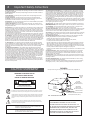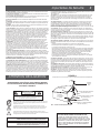
1
®
VM2860/VM2862
Commercial Video Modulator
(For use in NTSC systems)
Instruction Manual
VM SERIES VIDEO MODULATOR
® is a registered trademark of the R.L. Drake Holdings LLC
© Copyright 2015 R.L. Drake Holdings LLC
P/N: 651230900D
Printed in China
Rev: 20150814
1002470A/1002471A
2
Important Safety Instructions
1. Read Instructions—All the safety and operating instructions should be read before
the product is operated.
2. Retain Instructions—The safety and operating instructions should be retained for
future reference.
3. Heed Warnings—All warnings on the product and in the operating instructions
should be adhered to.
4. Follow Instructions—All operating and use instructions should be followed.
5. Cleaning—Unplug this product from the wall outlet before cleaning. Do not use
liquid cleaners or aerosol cleansers. Use a damp cloth for cleaning.
6. Attachments—Do not use attachments that are not recommended by the product
manufacturer as they may cause hazards.
7. Water and Moisture—Do not use this product near water—for example, near a
bathtub, wash bowl, kitchen sink or laundry tub; in a wet basement; or near a swimming pool; and the like.
8. Accessories—Do not place this product on an unstable cart, stand, tripod, bracket,
or table. The product may fall, causing serious injury to a child or adult, and serious
damage to the product. Use only with a cart, stand, tripod, bracket, or table recommended by the manufacturer, or sold with the product. Any mounting of the product
should follow the manufacturer’s instructions, and should use a mounting accessory
recommended by the manufacturer.
9. A product and cart combination should be moved with care. Quick stops, excessive
force, and uneven surfaces may cause the product and cart combination to overturn.
10. Ventilation—Slots and openings in the cabinet are provided for ventilation and to
ensure reliable operation of the product and to protect it from overheating, and these
openings must not be blocked or covered. The openings should never be blocked by
placing the product on a bed, sofa, rug, or similar surface. This product should not be
placed in a built-in installation such as bookcase or rack unless proper ventilation is
provided or the manufacturer’s instructions have been adhered to.
11. Power Sources—This product should be operated only from the type of power
source indicated on the marking label. If you are not sure of the type of power supplied to your home, consult your product dealer or local power company. For products
intended to operate from battery power, or other sources, refer to the operating
instructions.
12. Grounding or Polarization—This product may be equipped with a polarized
alternatingcurrent line plug (a plug having one blade wider than the other). This plug
will fit into the power outlet only one way. This is a safety feature. If you are unable to
insert the plug fully into the outlet, try reversing the plug. If the plug should still fail to
fit, contact your electrician to replace your obsolete outlet. Do not defeat the safety
purpose of the polarized plug. Alternate Warnings—If this product is equipped with
a three-wire grounding-type plug, a plug having a third (grounding) pin, the plug will
only fit into a grounding-type power outlet. This is a safety feature. If you are unable
to insert the plug into the outlet, contact your electrician to replace your obsolete
outlet. Do not defeat the safety purpose of the grounding-type plug.
13. Power-Cord Protection—Power-supply cords should be routed so that they are
not likely to be walked on or pinched by items placed upon or against them, paying
particular attention to cords at plugs, convenience receptacles, and the point where
they exit from the product.
CAUTION STATEMENT
14. Outdoor Antenna Grounding—If an outside antenna or cable system is connected to the product, be sure the antenna or cable system is grounded so as to provide
some protection against voltage surges and built-up static charges. Article 810 of the
National Electrical Code, ANSI/NFPA 70, provides information with regard to proper
grounding of the mast and supporting structure, grounding of the lead-in wire to an
antenna discharge unit, size of grounding conductors, location of antenna-discharge
unit, connection to grounding electrodes, and requirements for the grounding electrode. See Figure A.
15. Lightning—For added protection for this product during a lightning storm, or when
it is left unattended and unused for long periods of time, unplug it from the wall outlet
and disconnect the antenna or cable system. This will prevent damage to the product
due to lightning and power-line surges.
16. Power Lines—An outside antenna system should not be located in the vicinity of
overhead power lines, other electric light or power circuits, where it can fall into such
power lines or circuits.
17. Overloading—Do not overload wall outlets, extension cords, or integral convenience receptacles as this can result in a risk of fire or electric shock.
18. Object and Liquid Entry—Never push objects of any kind into this product through
openings as they may touch dangerous voltage points or short-out parts that could
result in a fire or electric shock. Never spill liquid of any kind on the product.
19. Servicing—Do not attempt to service this product yourself as opening or removing
covers may expose you to dangerous voltage or other hazards. Refer all servicing to
qualified service personnel.
20. Damage Requiring Service—Unplug this product from the wall outlet and refer
servicing to qualified service personnel under the following conditions:
a. When the power-supply cord or plug is damaged,
b. If liquid has been spilled, or objects have fallen into the product,
c. If the product has been exposed to rain or water,
d. If the product does not operate normally by following the operating instructions.
Adjust only those controls that are covered by the operating instructions as an improper adjustment of other controls may result in damage and will often require extensive work by a qualified technician to restore the product to its normal operation,
e. If the product has been dropped or damaged in any way, and
f. When the product exhibits a distinct change in performance—this indicates a need
for service.
21. Replacement Parts—When replacement parts are required, be sure the service
technician has used replacement parts specified by the manufacturer or have the
same characteristics as the original part. Unauthorized substitutes may result in fire,
electric shock or other hazards.
22. Safety Check—Upon completion of any service or repairs to this product, ask the
service technician to perform safety checks to determine that the product is in proper
operating condition.
23. Wall or Ceiling Mounting—The product should be mounted to a wall or ceiling
only as recommended by the manufacturer.
24. Heat—The product should be situated away from heat sources such as radiators,
heat registers, stoves, or other products (including amplifiers) that produce heat.
FIGURE A
Example of antenna grounding as per National Electrical Code, ANSI/NFPA 70
WARNING: TO PREVENT FIRE OR
ELECTRICAL SHOCK DO NOT
EXPOSE TO RAIN OR MOISTURE
! CAUTION !
ANTENNA
LEAD IN
WIRE
GROUND CLAMP
ANTENNA
DISCHARGE UNIT
(NEC SECTION 810-20)
RISK OF ELECTRIC SHOCK
DO NOT OPEN
WARNING: TO REDUCE THE RISK OF ELECTRIC SHOCK, DO NOT
REMOVE POWER SUPPLY COVERS
NO USER-SERVICEABLE PARTS INSIDE
REFER SERVICING TO QUALIFIED PERSONNEL
ELECTRIC
SERVICE
EQUIPMENT
GROUNDING
CONDUCTORS
(NEC SECTION 810-21)
GROUND CLAMPS
An appliance and cart combination should be moved with care. Quick stops, excessive
force and uneven surfaces may cause the appliance and cart combination to overturn.
The lightning flash with arrow head symbol, within an equilateral triangle, is intended to
alert the user to the presence of uninsulated “dangerous voltage” within the product’s
enclosure that may be of sufficient magnitude to constitute a risk of electric shock to
persons.
The exclamation point within an equilateral triangle is intended to alert the user to
the presence of important operating and maintenance (servicing) instructions in the
literature accompanying the appliance.
WARNING:
CAUTION:
TO REDUCE THE RISK OF FIRE OR ELECTRIC SHOCK, DO NOT EXPOSE THIS
APPLIANCE TO RAIN OR MOISTURE. DO NOT OPEN THE CABINET, REFER
SERVICING TO QUALIFIED PERSONNEL ONLY.
TO PREVENT ELECTRIC SHOCK, DO NOT USE THIS (POLARIZED) PLUG WITH AN
EXTENSION CORD RECEPTACLE OR OTHER OUTLET UNLESS THE BLADES CAN
BE FULLY INSERTED TO PREVENT BLADE EXPOSURE.
POWER SERVICE GROUNDING ELECTRODE
SYSTEM (NEC ART 250, PART H)
NEC - NATIONAL ELECTRIC CODE
NOTE TO CATV SYSTEM INSTALLERS:
THIS REMINDER IS PROVIDED TO CALL THE CATV
SYSTEM INSTALLER’S ATTENTION TO ARTICLE 820 - 40
OF THE NEC WHICH PROVIDES GUIDELINES FOR PROPER
GROUNDING AND, IN PARTICULAR, SPECIFIES THAT
THE CABLE GROUND SHALL BE CONNECTED TO THE
GROUNDING SYSTEM OF THE BUILDING, AS CLOSE TO
THE POINT OF CABLE ENTRY AS PRACTICAL.
3
Importantes De Sécurité
1. Lire les directives—Toutes les directives de sécurité et d’utilisation devraient être
lues avant de mettre l’appareil en opération.
2. Conserver les directives—Les directives de sécurité et d’utilisation devraient être
conservées pour consultation future.
3. Tenir compte des avertissements—Tous les avertissements apparaissant sur l’appareil et dans les consignes d’utilisation devraient être respectés.
4. Suivre les directives—Toutes les directives d’opération et d’utilisation devraient
être suivies.
5. Nettoyage—Débrancher l’appareil de la prise électrique murale avant le nettoyage.
Ne pas utiliser de nettoyants liquides ou aérosols. Employer un linge humide pour le
nettoyage.
6. Fixation—Ne pas utiliser d’autres fixations que celles recommandées par le manufacturier; elles pourraient être source de dangers.
7. Eau et humidité—Ne pas utiliser cet appareil près de l’eau. Par exemple, près d’une
baignoire, d’un bac de lavage, d’un évier de cuisine ou d’une cuvette de lessivage; dans
un sous-sol humide; ou à proximité d’une piscine; et autres environnements similaires.
8. Accessoires—Ne pas installer cet appareil sur un chariot, un socle, un trépied, un
support ou une table instables. L’appareil pourrait tomber, entraînant des blessures
graves à un enfant ou à un adulte, et des dommages importants à l’appareil. Employer
seulement avec un chariot, un socle, un trépied, un support, ou une table recommandés par le fabricant ou vendu avec l’appareil. Toute installation de l’appareil
devrait être conforme aux directives du manufacturier et devrait utiliser des accessoires d’installation recommandés par celui-ci.
9. Un chariot supportant l’appareil devrait être déplacé avec précaution. Les arrêts
brusques, la force excessive et les surfaces inégales peuvent renverser le chariot.
10. Ventilation—Des fentes et ouvertures dans le châssis sont prévues pour la
ventilation de l’appareil, pour en assurer la fiabilité d’opération et le protéger contre
la surchauffe. Ces ouvertures ne doivent pas être bloquées ou recouvertes. Ces
ouvertures ne devraient jamais être bloquées en plaçant l’appareil sur un lit, un sofa,
une couverture, ou une surface semblable. Cet appareil ne devrait pas être installé
dans un meuble encastré comme une bibliothèque ou une étagère à moins de lui
fournir une ventilation adéquate ou que l’installation soit conforme aux directives du
manufacturier.
11. Sources d’alimentation électrique—Cet appareil devrait être utilisé seulement
avec le type d’alimentation électrique inscrite sur l’étiquette. Si vous n’êtes pas certain
du type d’alimentation électrique fourni à votre maison, consultez le vendeur de l’appareil ou l’entreprises d’énergie locale. Pour des appareils alimentés par une batterie
ou d’autres sources, se référer aux consignes d’utilisation.
12. Mise à la terre ou Polarisation—Cet appareil est équipé avec un cordon d’alimentation à trois fils. Il est a brancher sur une prise ayant un connecteur a la terre.
Assurez-vous que la connection a la terre ne manque pas.
13. Protection du cordon d’alimentation—Les cordons d’alimentation devraient être
disposés de façon à ce qu’on ne puisse marcher dessus ou qu’ils soient susceptibles
d’être coincés par des articles placés sur ou contre eux. Une attention particulière doit
être portée aux fiches, prises de courant, et aux points où ils sortent de l’appareil.
14. Mise à la terre de l’antenne extérieure—Si un système extérieur d’antenne ou de
câble est relié à l’appareil, s’assurer que le système d’antenne ou de câble est muni
d’une mise à la terre afin de fournir une certaine protection contre les surtensions et
les charges d’électricité statique. L’article 810 du code électrique national, ANSI/NFPA
70, fournit l’information nécessaire en ce qui concerne la mise à la terre appropriée du
mât et de la structure porteuse, la mise à la terre du câble de connexion à une unité
de décharge d’antenne, le calibre des conducteurs de mise à la terre, la location de
l’unité de décharge d’antenne, le raccordement aux électrodes de mise à la terre et les
spécifications pour les électrodes de mise à la terre.
Voir la figure A.
15. Foudre—Pour une protection supplémentaire de cet appareil pendant un orage
électrique, ou quand il est laissé sans surveillance et inutilisé pendant de longues
périodes, le débrancher de la prise électrique murale et déconnecter le système
d’antenne ou de câble. Ceci préviendra les dommages à l’appareil dus à la foudre et
aux surtensions.
16. Lignes électriques—Un système d’antenne extérieur ne devrait pas être situé à
proximité de lignes électriques aériennes ou de tout autre circuit électrique, où il
pourrait tomber sur de tels circuits ou lignes électriques. Lors de l’installation d’un
système d’antenne extérieur, d’extrêmes précautions devraient être prises afin de
prévenir tout contact avec des lignes ou circuits électriques. Entrer en contact avec de
tels circuits ou lignes électriques pourrait être fatal.
17. Surcharge—Ne pas surcharger les prises de courant murales, les rallonges électriques ou les prises de courant intégrées. Un risque d’incendie ou de choc électrique
pourrait résulter d’une telle surcharge.
18. Insertion d’objet ou de liquide—Ne jamais insérer d’objet par les ouvertures de
cet appareil. Il pourrait toucher des points de voltage dangereux ou court-circuiter des
pièces, ce qui pourrait résulter en incendie ou en choc électrique. Ne jamais verser de
liquide sur l’appareil.
19. Entretien—Ne pas essayer de faire soi-même l’entretien de cet appareil. En ouvrir
ou en retirer les couvercles pourrait vous exposer à des voltages dangereux ou à d’autres dangers. Confier tout entretien à un personnel de service qualifié.
20. Dommage exigeant un entretien—Débrancher cet appareil de la prise de courant
électrique et confier l’entretien au personnel de service qualifié dans les éventualités
suivantes:
a. Quand le cordon d’alimentation ou sa fiche sont endommagés,
b. Si des objets sont tombés dans l’appareil, ou si du liquide y a été renversé,
c. Si l’appareil a été exposé à la pluie ou à l’eau,
d. Si l’appareil ne fonctionne pas normalement en suivant les consignes d’utilisation.
Ajuster seulement les commandes qui sont mentionnées dans le guide d’opération.
Un mauvais ajustement des autres commandes pourrait causer des dommages à
l’appareil et souvent exiger un travail supplémentaire de la part d’un technicien
qualifié pour remettre l’appareil en état normal d’opération.
e. Si l’appareil a été échappé ou endommagé de n’importe quelle façon, et
f. Quand l’appareil montre un changement notable de performance – ceci indique
qu’un entretien est nécessaire.
21. Pièces de rechange—Si des pièces de rechange sont nécessaires, s’assurer que le
technicien de service a employé des pièces de rechange spécifiques du manufacturier
ou ayant les mêmes caractéristiques que les pièces originales. L’utilisation de pièces
de rechange non autorisées pourrait résulter en incendie, choc électrique ou autres
dangers.
22. Vérification de sécurité—À la suite de toute réparation ou entretien de cet appareil, demander au technicien de service d’exécuter des vérifications de sécurité afin de
s’assurer que l’appareil est en condition normale de fonctionnement.
23. Montage au mur ou au plafond—L’appareil ne devrait être monté au mur ou au
plafond qu’uniquement de la façon recommandée par le manufacturier.
24. Chaleur—L’appareil devrait être situé loin de sources de chaleur telles que des
radiateurs, des registres de chaleur, des fourneaux, ou d’autres appareils (y compris
amplificateurs) produisant de la chaleur.
ATTENTION DÉCLARATION
Exemple de mise à la terre d’antenne selon le Code Électrique National, ANSI/NFPA 70
AVERTISSEMENT: AFIN D’ÉVITER TOUT RISQUE D’INCENDIE
OU D’ÉLECTROCUTION, NE PAS EXPOSER CET APPAREIL À LA
PLUIE OU À L’HUMIDITÉ.
FIGURE A
ANTENNA
LEAD IN
WIRE
ATTACHES DE
MISE À LA TERRE
! AVERTISSEMENT !
UNITÉ DE DÉCHARCHE D’ANTENNE
(NEC SECTION 810-20)
RISQUE DE CHOC ELECTRIQUE NE PAS OUVRIR
ATTENTION: POUR RÉDUIRE LE RISQUE D’ÉLECTROCUTION, NE PAS
ENLEVER LE DOS DE L’APPAREIL NI OUVRIR LE BOÎTIER. AUCUNE PIÈCE N’EST
RÉPARABLE PAR L’UTILISATEUR À L’INTÉRIEUR. SE RÉFÉRER UNIQUEMENT À
DES TECHNICIENS QUALIFIÉS POUR L’ENTRETIEN.
Une combinaison de l’appareil et chariot doit être déplacé avec précaution. Des arrêts
brusques, une force excessive et des surfaces inégales peuvent causer la combinaison
de l’appareil et le chariot.
APPAREILS
ÉLECTRIQUES
DE SERVICE
CONDUCTEURS DE MISE À LA TERRE
(NEC SECTION 810-21)
ATTACHES DE
MISE À LA TERRE
NEC - CODE ÉLECTRIQUE NATIONAL
SYSTÈME DE MISE À LA TERRE DU BÂTIMENT
(NEC ART 250, PART H)
Le symbole de l’éclair à l’intérieur d’un triangle équilatéral est destiné à alerter
l’utilisateur sur la présence d’une “tension dangereuse” non isolée dans le boîtier du
produit. cette tension est suffisante pour provoquer l’électrocution de personnes.
Le point d’exclamation à l’intérieur d’un triangle équilatéral est destiné à alerter
l’utilisateur sur la présence d’opérations d’entretien importantes au sujet desquelles des
renseignements se trouvent dans le manuel d’instructions.
AVERTISSEMENT:
AFIN D’ÉVITER TOUT RISQUE D’INCENDIE OU D’ÉLECTROCUTION, NE PAS
EXPOSER CET APPAREIL À LA PLUIE OU À L’HUMIDITÉ. NE PAS OUVRIR LE
BOÎTIER, CONFIER TOUS TRAVAUX À DU PERSONNEL TECHNIQUE QUALIFIÉ.
CAUTION:
POUR PREVENIR LES CHOCS ELECTRIQUES, NE PAS UTILISER CETTE FICHE
POLARISEE AVEC UN PROLONGATEUR, UNE PRISE DE COURANT OU UNE
AUTRE SORTIE DE COURANT, SAUF SI LES LAMES PEUVENT ETRE INSEREES A
FOND SANS EN LAISSER AUCUNE PARTIE A DECOUVERT.
NOTE AUX INSTALLATEURS DE SYSTÈME DE CATV:
CE RAPPEL EST FOURNI POUR PORTER À L’ATTENTION DES
INSTALLATEURS DE SYSTÈME DE CATV, L’ARTICLE 820 - 40 DU
NEC QUI DONNE DES DIRECTIVES POUR UNE MISE À LA TERRE
APPROPRIÉE ET, EN PARTICULIER, SPÉCIFIE QUE LE CÂBLE DE
MISE À LA TERRE DEVRAIT ÊTRE RACCORDÉ AU SYSTÈME DE
MISE À LA TERRE DU BÂTIMENT LE PLUS PRÈS POSSIBLE DE
L’ENTRÉE DU CÂBLE.
Table of Contents / Description / Specifications
4
TABLE OF CONTENTS
2
2
4
5
Caution Statements
Important Safety Instructions
Table of Contents / Description / Specifications
Front/Rear Panel Controls and Indicators
DESCRIPTION
The R.L Drake VM2860 and VM2862 Video Modulators are high quality, vestigial
sideband units with synthesized visual and aural carriers. They are designed
to accept NTSC video and audio baseband signals from a satellite receiver or
similar equipment. Front panel video and audio level controls with accompanying
modulation indicators permit easy setup of the proper modulation levels. The
A/V ratio and RF output level controls are also provided on the front panel. A rear
panel EAS alternate IF input is also provided. The VM2860 model is for applications
with mono audio and the VM2862 model provides BTSC stereo encoded audio.
Synthesized operation provides complete frequency agility, allowing front panel
selection of any standard CATV channel from 2 to 135 (54 to 862 MHz band).
FCC required offsets for aeronautical channels are automatically provided for
each channel that requires an offset. For special applications, IRC or HRC CATV
frequencies or off-air broadcast frequencies can be selected from the front panel.
6Operation
7Adjustments
8
Channel Assignments
A high quality IF SAW filter with FCC predistortion eliminates adjacent channel
interference and provides optimum delay characteristics.
A manual or auto-switching alternate IF input, labeled EAS input, is provided
for connection of an Emergency Alert System 44 MHz IF signal. When the EAS
IF signal appears at the EAS input, the main video and audio modulated IF is
replaced by the EAS input signal.
The EAS/Alternate IF feature allows a choice between manual and automatic
selection of the EAS/ALT IF input signal. This is done through a 3 position
terminal strip on the rear of the unit.
In the manual mode the EAS/ALT IF feature is activated by a contact closure
switch, which completes a ground connection. In the automatic mode, two
positions on the terminal strip are jumpered together enabling an automatic
detection circuit in the unit. When an EAS/ALT IF signal is routed to the EAS/ALT
port the unit automatically switches to that alternate signal.
SPECIFICATIONS - VM2860 / VM2862
VIDEO INPUT
Connector:
Impedance:
Return Loss:
Video Input Level:
Signal-to-Noise Ratio:
Differential Gain:
Differental Phase:
Over-modulation Indicator:
L/C Delay:
“F” Female
75 Ω
18 dB
0.7 volt Peak-to-Peak
58 dB
2.0%
1.0 degree
87 to 92%
Per FCC Requirements
RF OUTPUT
Connector:
Impedance:
Return Loss:
Channel Modes:
Power Level Range:
Video Flatness:
Carrier-to-Noise:
Broadband Noise:
Spurious Outputs:
Aural/Visual Carrier Ratio:
“F” Female
75 Ω
12 dB
CATV (STD,IRC,HRC) UHF, VHF
+50 to +60 dBmV
fv-0.5 to fv+4.2 MHz : 1.5 dB p/v
-63 dB
-77 dBc
-63 dBc
-15 ± 5 dB
GENERAL
AC Power:
Fuse:
Temperature Range:
Dimensions (WxDxH):
117 VAC ± 10%, 60 Hz, 29W max
0.4A Type T 250 V
32 to 122 °F (0 to 50 °C)
19.0 x 14.25 x 1.75 in
(482.6 x 361.95 x 44.45 mm)
Weight: 7 lbs. (3.18 kg)
MONO AUDIO (VM2860)
Connector:
Input Impedance:
Input Level:
Frequency Range:
Frequency Response:
Total Harmonic Distortion:
Signal-to-Noise Ratio:
Over-modulation Threshold:
RCA
Greater than 10k Ω, unbalanced
0.5 to 4.0 volt Peak-to-Peak
50 Hz to 15 kHz
± 0.5 dB
1% @ 25 kHz deviation
59 dB
25 ± 2 kHz peak deviation
STEREO AUDIO (VM2862 Only)
Connector:
Input Impedance:
Input sensitivity:
Frequency Response:
Separation:
Harmonic Distortion:
RCA
Greater than 10k Ω, unbalanced
0.7 volt Peak-to-Peak
± 0.75 dB
20 dB
Less than 1%
IF
Input/Output Connector: “F” Female
Aural Frequency: 41.25 MHz
Visual Frequency: 45.75 MHz
Composite IF Output
Aural:
Visual:
Input/Output Impedance:
Input/Output Return Loss:
EAS/Alternative IF
+20 dBmV
+35 dBmV
75 Ω
16/15 dB
Connector: “F” Female
Input Level: +35 dBmV @ 45.75 MHz
Switch Isolation:
Greater than 60dB
Front and Rear Panel Controls and Indicators
5
Opera
Controls
All opera
controls and indicators for the modulator are located on, or are accessible from the front panel.
[10]
VM SERIES VIDEO MODULATOR
[11]
[1]
[6] [5] [4] [3] [2]
[7]
[8]
[9]
Figure 1 - Front Panel
[1] EAS/ALT INDICATOR: Lights Red when EAS/ALT is ac ve.
is above 87.5%.
[2] VIDEO OVERMODULATION LED: Lights when modula
[3] VIDEO MODULATION LEVEL: Adjusts percentage of modula
.
[4] AURAL-TO-VISUAL CARRIER RATIO: Controls amplitude of aural RF carrier rela ve to visual RF carrier.
.
[5] AUDIO MODULATION LEVEL: Adjusts aural carrier modula
[6] AUDIO OVERMODULATION LED: Lights when peak devia
of aural carrier is over 25 kHz.
output level and modes.
[7] DISPLAY MODE BUTTON: Used to scroll through channel configura
[8] CHANNEL, CHANNEL CONFIGURATION/OUTPUT LEVEL DISPLAY
[9] UP/DOWN BUTTONS: Used to scroll through the channel, channel configuration and output level modes.
[10] ENTER BUTTON:
[11] STEREO INDICATOR: Green LED lights when equipped with stereo (VM2862).
Note: All c
to the unit are made at the rear panel.
[1]
[2]
[3]
[5]
[4]
[8]
[1] RF OUTPUT: + 60 dBmV
[2] IF INPUT: +35 dBmV IF Input
[3] EAS/ALT IF INPUT: Emergency Alert or Alternate IF Input
[4] IF OUT: +35 dBmV IF Output (See note #8 below)
[5] EAS/ALT IF TERMINAL: EAS/ ALT IF mode selection (see page 7)
[6] AUDIO INPUT: Audio input (standard)
[7] VIDEO INPUT: 1 Volt PP video input
[8] IF LOOP CABLE: The IF loop cable (supplied) must be installed to provide RF con
not have an RF output without the IF loop installed.
[6]
[7]
Figure 2 - Rear Panel (VM2860 Shown)
ty. The modulator will
6
Opera
Operation
n
Display Mode
of Channel, Channel Configura
Output Level mode in this order.
This bu on scrolls through the selec
The res g state (default) of the modulator’s display mode is the channel number.
Channel
The output channel is selected by pressing the UP or DN bu on when in the channel display mode.
state.
The LED display will blink indica g a transi
The actual channel is not changed un the ENTER bu on is pressed.
If the ENTER bu on is not pressed, the display will return to res g state a er 30 seconds.
Pressing and holding the UP or DN bu on will allow for faster scrolling of channel.
All internal a enuators are temporarily set for maximum a enua
during channel change (output is muted).
Channel Configura
The Channel Configura
is changed by pressing the UP or DN bu on when in the Channel Configura
display mode.
The LED display will blink indica g a transi
state.
is not changed un the ENTER bu on is pressed.
The channel configura
If the ENTER bu on is not pressed, the display will return to res g state a er 30 seconds.
If the mode is to be changed and it is not a valid mode for the exis g channel, when the ENTER bu on is pressed, the new
mode will be selected, and the channel will default to channel-2.
The available Channel Configura
are as follows:
C = Standard (default from factory)
I = IRC
H = HRC
U = Broadcast VHF/UHF
Error
The Display will show a flashing "EE1" if the PLL1 is not locked.
The Display will show a flashing "EE2" if the PLL2 is not locked.
The Display will show a flashing "EE3" if both PLL1 and PLL2 are not locked.
All internal a enuators are automa cally set for maximum a enua
in any of the above condi
occur.
Please contact our Service Department should any of these errors condi
(output is muted).
Adjustments
7
Adjustments
VIDEO LEVEL: With the intended signal source connected and a representa ve video program present turn the Video
Level Adjust control clockwise un the Video Overmodula
light just flashes, then back off slightly.
Alterna vely, while watching the picture on a good TV monitor, adjust the control to the highest (clockwise)
level that does NOT cause the highlights (white por
of the picture) to become “washed out”.
AUDIO LEVEL: Turn the Audio Level Adjust control clockwise un the Audio Overmodula
the loudest peaks of the audio program material.
light just flashes slightly on
OUTPUT LEVEL: The Output Level is adjusted by pressing the UP or DN bu on when in the Output Level display mode.
The LED display will blink indica g a transi on state. The output level is not changed un the ENTER
bu on is pressed. If the ENTER bu on is not pressed, the display will return to its res g state a er 30
seconds. Pressing and holding the UP or DN bu on will allow for faster scrolling. The Level increments in
0.2 dB steps. Output level accuracy is typically +/- 1 dB of display, +/- 2 dB worst case.
A/V CARRIER RATIO: To adjust the aural-to-visual carrier ra o, tune the RF indicator device to the aural carrier frequency
and adjust the Aural Carrier control to obtain the desired aural carrier level. Recommended ra is
-15 dB.
EAS/ALT IF:
AUTOMATIC: Connect a jumper to the terminal strip auto posi
a +38 dBmV EAS IF signal is detected.
MANUAL: EAS is ac ve with a ground connec
EAS will switch on when
on the manual posi
of the terminal strip.
8
Channel Assignments
TABLE 1: CATV
Output Channel
Switch Setting
EIA CH#
02
03
04
01
05
06
95
96
97
98
99
14
15
16
17
18
19
20
21
22
07
08
09
10
11
12
13
23
24
25
26
27
28
29
30
31
32
33
34
35
36
37
38
39
40
41
42
43
44
45
46
47
48
49
50
51
52
53
54
55
56
57
58
59
60
61
62
63
Visual Carrier Frequency
(MHz)
STD
IRC
55.2500
55.2625
61.2500
61.2625
67.2500
67.2625
NA
73.2625
77.2500
79.2625
83.2500
85.2625
91.2500
91.2625
97.2500
97.2625
103.2500
103.2625
109.2750
109.2750
115.2750
115.2750
121.2625
121.2625
127.2625
127.2625
133.2625
133.2625
139.2500
139.2625
145.2500
145.2625
151.2500
151.2625
157.2500
157.2625
163.2500
163.2625
169.2500
169.2625
175.2500
175.2625
181.2500
181.2625
187.2500
187.2625
193.2500
193.2625
199.2500
199.2625
205.2500
205.2625
211.2500
211.2625
217.2500
217.2625
223.2500
223.2625
229.2625
229.2625
235.2625
235.2625
241.2625
241.2625
247.2625
247.2625
253.2625
253.2625
259.2625
259.2625
265.2625
265.2625
271.2625
271.2625
277.2625
277.2625
283.2625
283.2625
289.2625
289.2625
295.2625
295.2625
301.2625
301.2625
307.2625
307.2625
313.2625
313.2625
319.2625
319.2625
325.2625
325.2625
331.2750
331.2750
337.2625
337.2625
343.2625
343.2625
349.2625
349.2625
355.2625
355.2625
361.2625
361.2625
367.2625
367.2625
373.2625
373.2625
379.2625
379.2625
385.2625
385.2625
391.2625
391.2625
397.2625
397.2625
403.2500
403.2625
409.2500
409.2625
415.2500
415.2625
421.2500
421.2625
427.2500
427.2625
433.2500
433.2625
439.2500
439.2625
445.2500
445.2625
451.2500
451.2625
457.2500
457.2625
HRC
54
60
66
72
78
84
90
96
102
Cannot lock to comb
ref: refer to FCC regs
120
126
132
138
144
150
156
162
168
174
180
186
192
198
204
210
216
222
228
234
240
246
252
258
264
270
276
282
288
294
300
306
312
318
324
330
336
342
348
354
360
366
372
378
384
390
396
402
408
414
420
426
432
438
444
450
456
Output Channel
Switch Setting
EIA CH#
64
65
66
67
68
69
70
71
72
73
74
75
76
77
78
79
80
81
82
83
84
85
86
87
88
89
90
91
92
93
94
100
101
102
103
104
105
106
107
108
109
110
111
112
113
114
115
116
117
118
119
120
121
122
123
124
125
126
127
128
129
130
131
132
133
134
135
Visual Carrier Frequency
(MHz)
STD
IRC
463.2500
463.2625
469.2500
469.2625
475.2500
475.2625
481.2500
481.2625
487.2500
487.2625
493.2500
493.2625
499.2500
499.2625
505.2500
505.2625
511.2500
511.2625
517.2500
517.2625
523.2500
523.2625
529.2500
529.2625
535.2500
535.2625
541.2500
541.2625
547.2500
547.2625
553.2500
553.2625
559.2500
559.2625
565.2500
565.2625
571.2500
571.2625
577.2500
577.2625
583.2500
583.2625
589.2500
589.2625
595.2500
595.2625
601.2500
601.2625
607.2500
607.2625
613.2500
613.2625
619.2500
619.2625
625.2500
625.2625
631.2500
631.2625
637.2500
637.2625
643.2500
643.2625
649.2625
649.2500
655.2500
655.2625
661.2500
661.2625
667.2500
667.2625
673.2500
673.2625
679.2500
679.2625
685.2500
685.2625
691.2500
691.2625
697.2500
697.2625
703.2500
703.2625
709.2500
709.2625
715.2500
715.2625
721.2500
721.2625
727.2500
727.2625
733.2500
733.2625
739.2500
739.2625
745.2500
745.2625
751.2500
751.2625
757.2500
757.2625
763.2500
763.2625
769.2500
769.2625
775.2500
775.2625
781.2500
781.2625
787.2500
787.2625
793.2500
793.2625
799.2500
799.2625
805.2500
805.2625
811.2500
811.2625
817.2500
817.2625
823.2500
823.2625
829.2500
829.2625
835.2500
835.2625
841.2500
841.2625
847.2500
847.2625
853.2500
853.2625
859.2500
859.2625
HRC
462
468
474
480
486
492
498
504
510
516
522
528
534
540
546
552
558
564
570
576
582
588
594
600
606
612
618
624
630
636
642
648
654
660
666
672
678
684
690
696
702
708
714
720
726
732
738
744
750
756
762
768
774
780
786
792
798
804
810
816
822
828
834
840
846
852
858
9
Channel Assignments, continued
TABLE 2: BROADCAST TV
UHF BROADCAST CHANNELS
VHF BROADCAST CHANNELS
UHF BROADCAST CHANNELS
Channel Number
Visual Carrier
Frequency (MHz)
Channel Number
Visual Carrier
Frequency (MHz)
Channel Number
Visual Carrier
Frequency (MHz)
2
55.25
14
471.25
47
669.25
3
61.25
15
477.25
48
675.25
4
67.25
16
483.25
49
681.25
5
77.25
17
489.25
50
687.25
6
83.25
18
495.25
51
693.25
7
175.25
19
501.25
52
699.25
8
181.25
20
507.25
53
705.25
9
187.25
21
513.25
54
711.25
10
193.25
22
519.25
55
717.25
11
199.25
23
525.25
56
723.25
12
205.25
24
531.25
57
729.25
13
211.25
25
537.25
58
735.25
26
543.25
59
741.25
27
549.25
60
747.25
28
555.25
61
753.25
29
561.25
62
759.25
30
567.25
63
765.25
31
573.25
64
771.25
32
579.25
65
777.25
33
585.25
66
783.25
34
591.25
67
789.25
35
597.25
68
795.25
36
603.25
69
801.25
37
609.25
70
807.25
38
615.25
71
813.25
39
621.25
72
819.25
40
627.25
73
825.25
41
633.25
74
831.25
42
639.25
75
837.25
43
645.25
76
843.25
44
651.25
77
849.25
45
657.25
78
855.25
46
663.25
10
Repairs and Returns
Service
A Return Material Authorization (RMA) Number is required on ALL PRODUCT RETURNS (regardless of whether the
product is being returned for repair or for credit). Product that is received at the factory without an RMA Number will be
returned to the sender, unopened.
RMA Numbers must be used when returning product for credit or repair. Use of RMA Numbers will ensure efficient
processing. When needing to return your product to R.L. Drake Holdings, LLC., please follow these simple steps listed
below (in the order that they appear).
SERVICE REPAIRS ONLY
CREDIT RETURNS ONLY
1. Contact R.L. Drake Holdings, LLC.’s Service Department
1. Contact R.L. Drake Holdings, LLC.’s Service Department
2. Request from Drake Service a copy of the Product Return
2. Request from Drake Service a copy of the Product Return
3. Complete the Product Return Authorization Form fully.
3. Complete the Product Return Authorization Form fully.
4. Return the completed Product Return Authorization Form
4. Return the completed Product Return Authorization Form
5. After completing Steps 1 through 4, an RMA Number will
5. After completing Steps 1 through 4, an RMA Number will
6. Securely pack the product and mark the box with your
6. Securely pack the product in its original undamaged box
in one of three ways:
Phone: 732-313-4256
Email: [email protected]
Fax: 732-679-4022
Authorization Form.
to the Drake Service Department using one of the contact
methods listed in Step 1.
be assigned to you.
RMA Number. If shipping multiple boxes, all boxes must
be marked with the RMA Number. Place the RMA Number
near the return address in large, bold print (approx. 2” in
height).
Ship your “SERVICE REPAIR ONLY” return to:
R.L. Drake Holdings, LLC.
Attn: Product Service Returns
One Jake Brown Road
Old Bridge, NJ 08857
in one of three ways:
Phone: 937-746-6990
Email: [email protected]
Fax: 937-806-1510
Authorization Form.
to the Drake Service Department using one of the contact
methods listed in Step 1.
be assigned to you.
(returning the product without its original packaging in
good, new condition may cause the incursion of additional
fees). Pack this box within another shipping container or
box. Mark the shipping box or container with your RMA
Number. Place the RMA Number near the return address
in large, bold print (approx. 2” in height).
Ship your “CREDIT RETURNS ONLY” return to:
R.L. Drake Holdings, LLC.
Attn: Product Credit Returns
One Jake Brown Road
Old Bridge, NJ 08857
*NOTE: All Credit Returns are subject to a 15% Restock Fee
*NOTE: All shipments are to be PRE-PAID by the sender. NO COD’s will be accepted.
IF YOU NEED TECHNICAL HELP
Call our Customer Service/Technical Support line at +1 (937) 746-6990 weekdays between 8:00 A.M. and 4:00 P.M. Eastern Standard
Time. Please have the unit’s serial number available. We will also need to know the specifics of any other equipment connected to the
unit. When calling, please have the unit up and running, near the phone if possible. Our technician(s) will likely ask certain questions to
aid in diagnosis of the problem. Also, have a voltmeter handy, if at all possible.
DRAKE also provides technical assistance by
Email: [email protected]
Fax: (937) 806-1510
Many of the products that are sent to us for repair are in perfect working order when we receive them. For these units, there is a
standard checkout fee that will be charged. Please perform whatever steps are applicable from the product’s Instruction Manual before
calling or writing as this could save unnecessary phone charges. Please do not return the product without calling Drake Service and
following the steps above first; it is preferred to help troubleshoot the problem over the phone (or by Email) first, saving you both time
and money.
Limited Warranty
11
Seller will at its sole option, either repair or replace (with a new or factory reconditioned product, as Seller may determine) any product manufactured or sold (or in the case of software,
licensed) by Seller which is defective in materials or workmanship or fails to meet the applicable specifications that are in effect on the date of shipment or such other specifications as may
have been expressly agreed upon in writing: (i) for a period of three (3) years from the date of original purchase for all stock hardware products (other than those specifically referenced herein
below having a shorter warranty period); (ii) for a period of one (1) year from the date of original purchase, with respect to all MegaPort™, IPTV products, test equipment and fiber optics
receivers, transmitters, couplers and integrated receiver/distribution amplifiers; (iii) for a period of one (1) year from the date of original purchase (or such shorter period of time as may be set
forth in the license agreement specific to the particular software being licensed from Seller) with respect to all software products licensed from Seller (other than Core Product Software) that
is (a) developed for a specific function or application, (b) complimentary to and does not function without the Core Product Software, and (c) listed with a specific model number and stock
number in Seller’s Price List (“Non-Core Software”); (iv) for a period of ninety (90) days from the date of original purchase, with respect to non-serialized products and accessories, such as
parts, sub-assemblies, splitters and all other products sold by Seller (other than Core Product Software and Refurbished/Closeout Products) not otherwise referred to in clauses (i) through (iii)
above. The warranty period for computer programs in machine-readable form included in a hardware product, which are essential for the functionality thereof as specifically stated in the published product specifications (“Core Product Software”) will be coincident with the warranty period of the applicable hardware product within which such Core Product Software is installed.
Software patches, bug fixes, updates or workarounds do not extend the original warranty period of any Core Product Software or Non-Core Software.
Notwithstanding anything herein to the contrary,
(i) Seller’s sole obligation for software that when properly installed and used does not substantially conform to the published specifications in effect when the software is first shipped by Seller,
is to use commercially reasonable efforts to correct any reproducible material non-conformity (as determined by Seller in its sole discretion) by providing the customer with: (a) telephone or
e-mail access to report non-conformance so that Seller can verify reproducibility, (b) a software patch or bug fix, if available or a workaround to bypass the issue if available, and (c) where
applicable, replacement or damaged or defective external media, such as CD-ROM disk, on which the software was originally delivered;
(ii) Seller does not warrant that the use of any software will be uninterrupted, error-free, free of security vulnerabilities or that the software will meet the customer’s particular requirements; and
the customer’s sole and exclusive remedy for breach of this warranty is, at Seller’s option, to receive (a) suitably modified software, or part thereof, or (b) comparable replacement software
or part thereof;
(iii) Seller retains all right, title and interest in and to and ownership of all software (including all Core Product Software and Non-Core Software) including any and all enhancements, modifications and updates to the same; and
(iv) in some cases, the warranty on certain proprietary sub-assembly modules manufactured by third-party vendors and contained in Seller’s products, third party software installed in certain of
Seller’s products, and on certain private-label products manufactured by third-parties for resale by Seller, will be of shorter duration or otherwise more limited than the standard Seller limited
warranty. In such cases, Seller’s warranty with respect to such third-party proprietary sub-assembly modules, third-party software and private-label products will be limited to the duration and
other terms of such third-party vendor’s warranty, if any. The limited warranty set forth above does not apply to any product sold by Seller, which at the time of sale constituted a Refurbished/
Closeout Product, the limited warranty for which is provided in the following paragraph.
Seller will at its sole option, either repair or replace (with a new or factory-reconditioned product, as Seller may determine) any product sold by Seller which at the time of sale constituted a
refurbished or closeout item (“Refurbished/Closeout Product”), which is defective in materials or workmanship or fails to meet the applicable specifications that are in effect on the date of
shipment of that product or fails to meet such other specifications as may have been expressly agreed upon in writing between the parties, for a period of ninety (90) days from the date of original
purchase. Notwithstanding the foregoing, in some cases the warranty on certain proprietary sub-assembly modules manufactured by third-party vendors and contained in Seller products, third
party software installed in certain of Seller’s products, and on certain private-label products manufactured by third-parties for resale by Seller will be of shorter duration or otherwise more limited than Seller limited warranty for Refurbished/Closeout Products. In such cases, Seller’s warranty for Refurbished/Closeout Products constituting such third party proprietary sub-assembly
modules, third party software, and private-label products will be limited to the duration and other terms of such third-party vendor’s warranty, if any. In addition, notwithstanding the foregoing,
(i) certain Refurbished/Closeout Products that are not manufactured (but are resold) by Seller, may carry the original OEM warranty for such products, if any, which may be longer or shorter
than Seller’s limited warranty for Refurbished/Closeout Products. All sales of Refurbished/Closeout Products are final.
To obtain service under this warranty, the defective product, together with a copy of the sales receipt, serial number if applicable, or any other satisfactory proof of purchase and a brief description of the defect, must be shipped freight prepaid to Seller at the following address: One Jake Brown Road, Old Bridge, New Jersey 08857.
This warranty does not cover failure of performance or damage resulting from (i) use or installation other than in strict accordance with manufacturer’s written instructions, (ii) disassembly
or repair by someone other than the manufacturer or a manufacturer-authorized repair center, (iii) misuse, misapplication or abuse, (iv) alteration, (v) exposure to unusual physical or electrical
stress, abuse or accident or forces or exposure beyond normal use within specified operational or environmental parameters set forth in applicable product specifications, (vi) lack of reasonable
care or (vii) wind, ice, snow, rain, lightning, or any other weather conditions or acts of God.
OTHER THAN THE WARRANTIES SET FORTH ABOVE, SELLER MAKES NO OTHER WARRANTIES OR REPRESENTATIONS OF ANY KIND, EXPRESS OR
IMPLIED, AS TO THE CONDITION, DESCRIPTION, FITNESS FOR A PARTICULAR PURPOSE, MERCHANTABILITY, OR AS TO ANY OTHER MATTER, AND SUCH
WARRANTIES SET FORTH ABOVE SUPERSEDE ANY ORAL OR WRITTEN WARRANTIES OR REPRESENTATIONS MADE OR IMPLIED BY SELLER OR BY ANY
OF SELLER’S EMPLOYEES OR REPRESENTATIVES, OR IN ANY OF SELLER’S BROCHURES MANUALS, CATALOGS, LITERATURE OR OTHER MATERIALS. IN
ALL CASES, BUYER’S SOLE AND EXCLUSIVE REMEDY AND SELLER’S SOLE OBLIGATION FOR ANY BREACH OF THE WARRANTIES CONTAINED HEREIN
SHALL BE LIMITED TO THE REPAIR OR REPLACEMENT OF THE DEFECTIVE PRODUCT F.O.B SHIPPING POINT, AS SELLER IN ITS SOLE DISCRETION
SHALL DETERMINE. SELLER SHALL IN NO EVENT AND UNDER NO CIRCUMSTANCES BE LIABLE OR RESPONSIBLE FOR ANY CONSEQUENTIAL, INDIRECT,
INCIDENTAL PUNITIVE, DIRECT OR SPECIAL DAMAGES BASED UPON BREACH OF WARRANTY, BREACH OF CONTRACT, NEGLIGENCE, STRICT TORT
LIABILITY OR OTHERWISE OR ANY OTHER LEGAL THEORY, ARISING DIRECTLY OR INDIRECTLY FROM THE SALE, USE, INSTALLATION OR FAILURE OF
ANY PRODUCT ACQUIRED BY BUYER FROM SELLER.
All claims for shortages, defects, and non-conforming goods must be made by the customer in writing within five (5) days of receipt of merchandise, which writing shall state with particularity
all material facts concerning the claim then known to the customer. Upon any such claim, the customer shall hold the goods complained of intact and duly protected, for a period of up to sixty
(60) days. Upon the request of Seller, the customer shall ship such allegedly non-conforming or defective goods, freight prepaid to Seller for examination by Seller’s inspection department
and verification of the defect. Seller, at its option, will either repair, replace or issue a credit for products determined to be defective. Seller’s liability and responsibility for defective products is
specifically limited to the defective item or to credit towards the original billing. All such replacements by Seller shall be made free of charge f.o.b. the delivery point called for in the original
order. Products for which replacement has been made under the provisions of this clause shall become the property of Seller. Under no circumstances are products to be returned to Seller without
Seller’s prior written authorization. Seller reserves the right to scrap any unauthorized returns on a no-credit basis. Any actions for breach of a contract of sale between Seller and a customer
must be commenced by the customer within thirteen (13) months after the cause of action as accrued. A copy of Seller’s standard terms and conditions of sale, including the limited warranty,
is available from Seller upon request. Copies of the limited warranties covering third-party proprietary sub-assembly modules and private-label products manufactured by third-parties may
also be available from Seller on request. (Rev 0713)
R.L. DRAKE HOLDINGS
Sales: 937-746-4556 • Support: 937-746-6990 • Fax: 937-806-1510
www.rldrake.com
R.L. Drake Holdings LLC
710 Pleasant Valley Drive
Springboro, Ohio 45066
Customer Service and Parts Telephone: +1 (937) 746-6990
Telefax: +1 (937) 806-1510
World Wide Web Site: http://www.rldrake.com