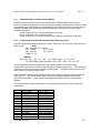
1
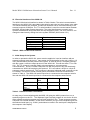
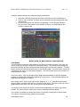
Mess-, Steuer- und Regelgeräte GmbH Model WOS-120 Miniature Angular Orientation Sensor MSP430 CPU Version User’s Manual and Technical Reference April 2011 Heppstrasse 30 ■ D-80995 München ■ Phone +49 (89) 313 30 07 ■ Fax +49 (89) 314 67 06 email: [email protected] ■ web site: www.wuntronic.de Mess-, Steuer- und Regelgeräte GmbH Table of Contents I ....... Introduction ............................................................................................................1 II ...... System Specifications2..........................................................................................2 III ..... Mechanical Features..............................................................................................2 IV ..... Electrical Interface .................................................................................................3 V ...... Initial Setup of the System .....................................................................................3 VI ..... Computer Interface ...............................................................................................4 6.1 ... WOS-120 Internal Constants .................................................................................4 6.2 ... ASCII Communication Mode..................................................................................6 6.3 ... Changing Data Output Mode .................................................................................6 6.4 ... Changing the Baud Rate........................................................................................7 6.5 ... Enabling Echoing of WOS-120 Input Commands ..................................................7 6.6 ... Entering a Serial Number into the WOS-120 Power On Message.........................7 6.7 ... Turn Off WOS-120 Power On Message.................................................................7 6.8 ... Configuring the WOS-120 for Autosend Modes.....................................................8 6.9 ... Averaging and Filtering of WOS-120 Data.............................................................8 6.10 . Single Packet Binary Communication Modes ........................................................8 6.11 . Autosend Binary Mode.........................................................................................10 Comparison of ASCII and Standard Binary Data ..........................................................10 Changing the WOS-120 Coordinate System (Optional)................................................12 VII .... Definition and Method of Calculation of the Orientation Sensor Angles ..............13 7.1 ... Sensor Based Coordinate System.......................................................................13 7.2 ... Definition of Orientation Angles ...........................................................................13 7.3 ... Definitions ............................................................................................................14 7.4 ... Calculation of Roll and Magnetic Roll ..................................................................14 7.5 ... Calculation of Inclination ......................................................................................14 7.6 ... Magnetic Heading (Azimuth)................................................................................15 VIII Windows Software for Model WOS-120 Orientation Sensor ..................................16 Sensor Angles Table 1 System Specifications…………………………………………...............................2 Table 2 WOS-120 Electrical Specifications……………………………………. .................3 Table 3 RS-232 Interface Connections…………………………………. ..........................3 Table 4 WOS-120 Operating Modes…………………………………………......................6 Table 5 Baud Rate Settings…………………………………………….. ............................7 Table 6 Autosend Modes………………………………………………................................8 Table 7 Binary Data Packets……………………………………………............................11 Figure 1 WOS-120 Mechanical Drawing ………………………………….. .................20 Figure 2 WOS-120 Coordinate System and Orientation Angles…………….. .............21 Appendix A Azimuth Accuracy Estimates …………………………. ............................22 Heppstrasse 30 ■ D-80995 München ■ Phone +49 (89) 313 30 07 ■ Fax +49 (89) 314 67 06 email: [email protected] ■ web site: www.wuntronic.de Model WOS-120 Miniature Orientation Sensor User’s Manual Rev. 1.1 I. Introduction This manual describes the Model WOS-120 orientation sensor. This system is designed to enable high accuracy measurement of the inclination, roll (or tool face) and azimuth orientation angles of the system to which it is mounted. A common application of the WOS120 is to measure the orientation of borehole logging and directional drilling systems. The Model WOS-120 orientation sensor contains both a 3 axis fluxgate magnetometer and a 3 axis accelerometer. The combination of these two sensor systems enables the inclination, roll and azimuth angles of the WOS-120 reference frame to be determined. Inclination and roll angles are determined from the accelerometer subsystem, which measures the pull of gravity. After inclination and roll are known, the magnetometer subsystem is used to determine system azimuth angle. Knowledge of the inclination and roll angles enable determination of the horizontal components of the earth's local magnetic field; this information defines the azimuth angle. The WOS-120 System contains a microprocessor and 8 channels of 16-bit analog to digital conversion. Six channels are assigned to the magnetometer and accelerometer outputs. One channel provides temperature data from an internal thermometer and one channel is configured to measure the system input voltage. The WOS-120 System communicates with the outside world over one of two serial bidirectional interfaces that can be selected for either TTL or RS-232 voltage levels. An ASCII character command language has been created to facilitate communication with the WOS120. For instance, if the ASCII string “0SD”<CR> is sent to the unit, the WOS-120 interprets this as a "send data" command and responds by sending over the serial interface an ASCII string representing the value of all magnetometer, accelerometer and temperature outputs. The leading zero in this sequence denotes the system serial number. The WOS-120 can also be configured to send angle data (roll, pitch and azimuth) instead of the accelerometer and magnetometer sensor data. An autosend data mode is included in the WOS-120 firmware. When this mode is active, data is repeatedly sent after power is applied to the system. The WOS-120 accelerometers are calibrated by placing the system in a precision rotation fixture and systematically changing the system orientation in the earth's gravitational field. The WOS-120 system magnetometers are calibrated by placing the system in a precision 3-axis Helmholtz coil system, which enables the application of known magnetic fields to the system. Both the rotation fixture and Helmholtz coil mounting fixture have alignment pins and reference surfaces, which mate to the WOS-120 reference surface. When the system is calibrated over a temperature range, data is read from the system at temperature intervals between the minimum and maximum temperature specification. For instance, for calibration over the interval of 0°C – 75°C, data is read at 25°C temperature intervals between 0° and 75°C. The data taken at each temperature includes scale, offset and sensor alignment data. The recorded data is then used to create a look up table for scale offset and alignment corrections. This table is then downloaded into the WOS-120 internal EEROM memory, where it can be accessed by the system internal microprocessor. Corrections to the read sensor data can then be made by the internal microprocessor system before data is transmitted. WUNTRONIC GmbH 1 Model WOS-120 Miniature Orientation Sensor User’s Manual Rev. 1.1 II. System Specifications Specification Angular Accuracy Azimuth Inclination Roll Power Voltage Current Value Notes ±1.2° ±0.4° ±0.4° Inclination=90 deg +4.9 to +12 VDC 55 mA Operating Temperature 0 °C – 70 °C Vibration Shock Size Mass Digital Outputs Logic Level Baud rate Protocol Leads 10 g RMS, random 20–250Hz 750 g 1ms half-sine 0.75" x 0.80" x 4.6" 50 grams Data output speed in autosend mode ASCII angle mode ASCII sensor mode Binary sensor mode TTL or RS-232 300 – 9600 baud ASCII text or Binary 6" flying leads Optional range of 0 to 125C available User selectable User selectable User selectable Color coded Data rates listed are for a filter setting of 30 Hz 6 Samples/sec 9 Samples/sec 18 Samples/sec Table 1. WOS-120 System Specifications III. Mechanical Features of the WOS-120 An outline drawing of the WOS-120 System is shown in Fig. 1. (All figures are at the end of this manual.) The system dimensions are 0.75" x 0.80" x 4.60" (1.90 cm x 2.03 cm x 11.68 cm). The system is normally mounted by using four 2-56 x 0.250 long screws to secure the WOS-120 reference surface to a flat mating surface. Two 0.062" dia. x 0.125" long pins protruding from the external mating surface can be used to orient the WOS-120 on the external mounting surface. The orientation of the X-, Y- and Z- axes and the approximate location of the magnetometer and accelerometer sensors are also shown in Figure 1. The output polarity sense of the axes is such that a field pointing in the direction of the arrows shown in Fig. 1 will produce a positive output voltage. For example, if the X magnetometer is oriented so the X-axis arrow points north, then the X-axis magnetometer output will record a positive value. If the X-axis accelerometer arrow is pointed down, the X-axis accelerometer output will be positive. The orientation of the axes is silk-screened onto the WOS-120 case. Fig. 2 shows the definition of the angles output by the WOS-120. WUNTRONIC GmbH 2 Model WOS-120 Miniature Orientation Sensor User’s Manual Rev. 1.1 IV. Electrical Interface of the WOS-120 The WOS-120 electrical interface is shown in Table 2 below. The serial communications interface to the WOS-120 is provided by the serial in and serial out lines shown in the table. Two serial interfaces are provided. The RS-232 interface can be connected directly to an external computer COM port. The TTL serial interface is used for communication between the WOS-120 and other system electronics. The serial interfaces are normally set to operate at 9600 baud using 8 bits with one stop bit and no parity. The user, however, can change the baud rate by setting bits in the system EEROM. (See Section VIII.) Wire Color Red Black Orange Yellow White/Orange White/Yellow Function +4.9 to +12 VDC Unregulated Ground RS-232 Serial In RS-232 Serial Out TTL Serial In TTL Serial Out Table 2. WOS-120 Electrical Interface V. Initial Setup of the System In order to operate the WOS-120, power must be applied to it and an interface with an external computer must be set up. Input power should be applied to the red (+4.95 to +12 VDC) and the Black (Ground) wires of the system. In order to set up a computer interface with the system, select the output protocol of the WOS-120. This can be either TTL or RS232. The TTL protocol is usually used in microprocessor-to- microprocessor communications. Since PC serial COM ports use RS-232 protocol, they can be directly connected to a WOS-120 employing this protocol. PC’s use either a 25-pin or a 9-pin D connector on their serial ports. This connector is always a bulkhead male connector on the PC chassis. The serial in, serial out and ground connections for these connectors are shown in Table 4. The WOS-120 serial output line is connected to the computer serial in line and the WOS-120 serial input line is connected to the computer serial out line. Function WOS-120 Serial In WOS-120 Serial Out Ground WOS-120 Wire Orange 25-Pin D 9-Pin D 2 3 Yellow 3 2 Black 5 5 Table 3. RS-232 Interface Connections An easy way of communicating with the WOS-120 using the ASCII protocol is to run a terminal program on the PC. The Windows HyperTerminal program is one choice for this. Other suitable terminal programs are ProComm and ASCII Pro. These programs turn the computer into a dumb terminal. In this mode, whatever you type on the keyboard goes out the selected serial port (e.g. COM 1) and whatever comes in the serial port is displayed on the computer video display. WUNTRONIC GmbH 3 Model WOS-120 Miniature Orientation Sensor User’s Manual Rev. 1.1 If the program HyperTerminal is used, the proper Com port (e.g. COM 1, COM 2, etc.) must be selected. In addition, a baud rate of 9600 with one stop bit and no parity must be selected. Set the port up for direct connect and select “none “ for handshaking. After setting up communications with an external computer the WOS-120 will respond with the following startup message when power is turned on: APS: S/Nxxxxxxxxxx Ver: 3.67 Bow Dip In the above messages, the x’s represent the unit serial number. A Second method of communicating with the WOS-120 is to use the Windows program Sensor.exe described in section VIII of this manual. VI Computer Interface of the WOS-120 6.1 WOS-120 Internal Binary and Float Constants The operating characteristics of the WOS-120 are controlled by the value of internal binary constants. The most important constants are: Binary constant Function 00 enables echoing when non zero 01 enables autosend upon power up when = 5A 02 enables sensor A/D count output when zero, calibrated sensor output (in Gauss and Gees) when =2 and angle output (roll, pitch, azimuth) when =3 (Alternate labels Roll: Pitch: Az: ) when =4 05 08 09 10 23 35 Controls sending of power up sign on message (default=0, message enabled) Sets power on mode (e.g., 10 enables ASCII autosend upon power up) Baud rate lock (must be =5A if any baud rate other than 9600 is used) Sets baud rate Sets up averaging of the output Sets delay between transmissions in autosend mode In order to change the internal system binary constants, a write enable command must first be issued. This is: 0l <CR> Where 0 is zero, l is the letter L (lower case or capital) and <CR> is a carriage return. When this command is sent to the WOS-120, it will respond with the reply enabled! To write byte constant 02=03, the command 0WC0203b03 <CR> WUNTRONIC GmbH 4 Model WOS-120 Miniature Orientation Sensor User’s Manual Rev. 1.1 is issued. After receiving this and acting upon it, the WOS-120 will respond with the reply done The reading of internal constants can be accomplished by issuing the command 0SC02b <CR> (0 Send Constant 02 binary). When this command is sent, the WOS-120 will respond by sending the value of constant 02. Wildcards are also recognized. The command OSC*b will cause the WOS-120 to send the value of all internal binary constants. In addition to internal byte constants, the WOS-120 also has a number of float constants. These are used to store the calibration data in the WOS-120 EEROM. These constants can be read by using the commands 0SC*f <CR> for all constants 0SC06F <CR> for constant 06 The most important float constants are: Float Constant 04 05 06 07 08 09 10 11 12 13 14 15 Description X Magnetometer Offset Y Magnetometer Offset Z Magnetometer Offset X Accelerometer Offset Y Accelerometer Offset Z Accelerometer Offset X Magnetometer scale Y Magnetometer scale Z Magnetometer scale X Accelerometer scale Y Accelerometer scale Z Accelerometer scale Float constants 16 to 34 contain the system alignment coefficients. For example, float constant 17 contains data on the magnetometer X sensor alignment in the Y direction. The WOS-120 sensor is temperature compensated to insure that the accuracy of the sensor is maintained over its intended temperature range. The temperature calibration data is stored in the system EEROM memory. This data can be accessed by using the following commands: 0st*b <CR> 0st*i <CR> 0st*f <CR> 6.2 Send temperature calibration table in binary format Send temperature calibration table in integer format Send temperature calibration table in floating format ASCII Communication Mode WUNTRONIC GmbH 5 Model WOS-120 Miniature Orientation Sensor User’s Manual Rev. 1.1 Communication is initiated when the external computer issues a command such as ASCII characters 0SD. The characters 0SD stand for 0 Send Data. When this command is issued, the WOS-120 will respond with a formatted output similar to the following: MX:+0.20346 AX:-0.07852 MY:+0.23165 AY:+0.72136 MZ:+0.29525 AZ:+0.70226 T: +28.148 When internal binary constant 02=02, the WOS-120 is in sensor output mode and the above numbers represent the magnetometer X, Y and Z sensor outputs in Gauss and the accelerometer outputs in Gees. When binary byte 02=03, the WOS-120 is in angle mode and The WOS-120 responses to a send data command with the following format, MX: +35.17825 MY: +90.14559 MZ: +26.76792 T: +28.026 AX: +198.24032 AY: +0.43326 AZ: +1.00101 DA: 55.893 When binary byte 02=04, the WOS-120 is in angle mode and The WOS-120 responses to a send data command with the following format, ROLL: +35.17825 PITCH: +90.14559 HEAD: +26.76792 TEMP: +28.026 MAGROLL: +198.24032 MAG: +0.43326 GRAV: +1.00101 DA: 55.893 where ROLL is gravity roll (or toolface), PITCH is inclination, HEAD is Azimuth, MAGROLL is magnetic roll, MAG is the total magnetic field, GRAV is the total gravity field , and DA is the magnetic field dip angle 6.3 Changing Data Output Mode The WOS-120 can be configured to output in raw ADC counts, sensor values or angles. Data output format is determined by the value of binary constant 02 as follows: Binary 02 value 0x00 Output data format Raw A/D Counts (Uncalibrated) 0x02 Calibrated Sensor Outputs (Accelerometer and Magnetometers) 0x03 Angular Outputs (Roll, Inc, Azimuth) 0x04 Angular Outputs with Alternate labels Table 4. WOS-120 Operating Modes 6.4 Changing the Baud Rate The communications baud rate can be changed by using the following sequence: 1. Set binary constant 10 according to Table 1. 2. Set binary constant 09 to 0x5a. 3. Cycle power off and on. WUNTRONIC GmbH 6 Model WOS-120 Miniature Orientation Sensor User’s Manual Rev. 1.1 The following commands illustrate setting the baud rate to 2400. 0l<CR> 0wc10b32<CR> 0l<CR> 0wc09b5a<CR> When byte constant 09 is set to any value other than 0x5a, the system baud rate is 9600. Baud Rate 300 1200 2400 4800 9600 19,200 38,400 Byte 10 Value 0x35 0x33 0x32 0x31 0x30 0x38 0x05 Table 5. Baud Rate Settings 6.5 Enable the Echoing of Incoming Commands It is usually desirable to enable the WOS-120 to echo the command characters sent to it. To do this, the value of the binary constant 00 must be set to a non-zero value by issuing the following sequence of commands: 0l<CR> 0wc00b01<CR> 6.6 Enter a serial number into the WOS-120 power up sign on message Up to 10 digits of serial number can be embedded into the unit sign on message by issuing the following commands: 0l<CR> 0tv=xxxxxxxxxx<CR> 6.7 Turn off the WOS-120 power up sign on message The WOS-120 power on message can be turned off by setting binary constant 5 to a nonzero value. Resetting binary constant 5 to 0 will enable the turn on message. 6.8 Configuring for Autosend To configure the WOS-120 for autosend, binary constant 01 must to be set to 0x5a and binary constant 08 needs to be set in accordance with table 2. WUNTRONIC GmbH 7 Model WOS-120 Miniature Orientation Sensor User’s Manual AUTOSEND MODE Rev. 1.1 Binary Byte 08 Value Send ASCII data continuously on power up Send Binary Data Continuously on power up 0x10 0x11 Table 6. Autosend Modes 6.9 Averaging and filtering of WOS-120 Output Data Averaging of the acquired data can be enabled by setting binary constant 23 according to the table shown below. The response times shown are for a full scale change in a sensor output e.g. a change from 0 gee to 1.0gee for an accelerometer or a change from 0 Gauss to 0.5 Gauss for a magnetometer. Binary constant 23 value Number of averages Time to reach n 90% of final value (seconds) 2 4 8 10 20 40 2 4 8 16 32 64 .94 1.87 3.25 7.5 15 30 Time to reach to within 0.001 gee or 0.001 Gauss of final value (seconds) 1.87 3.75 7.5 15 30 60 The above averaging times assume that the A to D low pass filter frequency (see discussion of the feature in the next paragraph) is set to 30 Hz. The averaging times are proportional to this frequency so for instance if the low pass filter frequency is set to 60 Hz and the number of averages is set to 8 then the time to reach 90% of the final output is 1.62 seconds. Each data output of the WOS-120 is a running average of the previous n data acquisitions. When a new data point is acquired, a new average is computed by dropping the oldest data point from the average and adding the new data point. The maximum average is 64 samples. This average feature is useful for high vibration environments when the user knows the attitude is changing slowly, but vibration produces a large amount of noise in the WOS-120 output. 6.10 Single Packet Binary Communication Modes In addition to an ASCII communication mode, the WOS-120 also has several binary communications modes: Single data packet binary communications are initiated by an external computer by the issuance of a single byte command, e.g., ASCII 128. On some computers, these commands can be sent from a terminal emulator program by holding the control key down and typing the command number on the number pad on the right side of the keyboard. Command Command Definition ASCII 128 send sensor data in binary format WUNTRONIC GmbH 8 Model WOS-120 Miniature Orientation Sensor User’s Manual ASCII 131 Rev. 1.1 send angle data in binary format The WOS-120, upon receiving one of these commands, responds by sending a binary data packet with one of the structures described below. Command <128> Sends All Data in an encoded Binary Format. The data is returned as: <<Sent First <<<<<<<<<<<<<<<<<<<<<<<<<<<<<<<<<<<<<<<<<<Sent Last<<<< <SOT><MX><AX><MY><AY><MZ><AZ><MT><V><Status><DATA CHECK SUM> <END> 8bits 16b 16b 16b 16b 16b 16b 16b 16b 8b 8b 16b 16b <END>= 0x7FFF (should be unique in the data stream) <SOT>= 16Decimal or 10 Hex <Status>= a constant 0x80, not used in the WOS-120 <DATA CHECK SUM>= The lower 8 bits of the sum of all the bytes in the data area. <MX>,<MY>,<MZ> = The Mag. Data encoded as below. <AX>,<AY>,<AZ> = The Acc. Data encoded as below. <MT>= The Temp Data encoded as below. <V>= Downhole voltage All Data is Sent most significant byte first. The Mag and Acc Data is in a two byte signed integer format encoded as the float value times10000. (for example 0.2345 is encoded as 2345 ) The Temp Data is in a two byte signed integer format encoded as the float value times 100. ( 123.45 = 12345 ) The Downhole voltage is a two byte signed integer format encoded as the float value multiplied by 100 (12.0 encoded as 1200) Command <131> Sends All Angle Data in an encoded Binary Format. The data is returned as: <<<<Sent First <<<<<<<<<<<<<<<<<<<<<<<<<<<<<<<<<<<<<<<<Sent Last<<<< <SOT><Roll><MagRoll><Inclination><TotMag><Head><TotGrav><MT><V><Status><Data Check Sum><END> 8b 16b 16b 16b 16b 16b 16b 16b 16b 8b 8b 16b <END>= 0x7FFF (should be unique in the data stream) <SOT>= 16 Decimal or 10 Hex <0>= a constant 0x80, not used in the WOS-120 <DATA CHECK SUM>= The lower 8 bits of the sum of all the bytes in the data area. <MT>,<V> = The Temp and downhole voltage data encoded as below. All Data is Sent most significant byte first. All angles are encoded by multiplying the angle by 10(e.g.123.56=1235.6) The Temp data is in a two byte signed integer format encoded as the float value times 100. ( 123.45 = 12345 ) The downhole Voltage is a two byte signed integer format encoded by multiplying by 10 (10.0=100) WUNTRONIC GmbH 9 Model WOS-120 Miniature Orientation Sensor User’s Manual 6.11 Rev. 1.1 Autosend Binary Communication Modes Autosend binary protocol results in the transmission of data packets with the same structure as that described above for the response to binary command 128. However, when in autosend mode, data packets are automatically and continuously sent out after power is applied. Standard autosend binary mode is selected by setting up the system binary constants as follows: binary constant 08=11 selects autosend continuously binary constant 01=5a autosend enable binary constant 35=10 inserts a small delay between data packets (optional) 6.12 Comparison of ASCII and standard binary data structures Consider the following data transmissions from a WOS-120, one in ASCII mode and one in Binary mode: ASCII: MX: +0.3598 AX: +0.2740 MY: -0.2490 AY: -0.3510 MZ: +0.0145 AZ: +0.4711 TEMP: 21.74 BINARY: SOT MX AX MY AY MZ AZ TEMP ANA1 ST CS EOT 10 0E0E 0AB4 F646 F24A 0091 1267 087E 0320 80 05 7FFF The two data transmissions transmit the same data content, but the ASCII data transmission uses about 8 times more bytes than the binary transmission. The binary data packet is a much more efficient method of sending data. In addition, binary data is often much easier to parse than ASCII data. WOS-120 binary data packets will always start with a header byte 0x10 and end with two bytes 0x7FFF. The data is always sent most significant byte (MSB) first, then least significant byte (LSB). Angle, sensor and temperature data is sent as 16-bit signed integers. The following table shows the definition of the binary data packet for sensor mode and angle mode. Byte 01 02 03 04 05 06 07 08 09 10 11 12 13 14 Sensor mode SOT = 0x10 MX MSB MX LSB AX MSB AX LSB MY MSB MY LSB AY MSB AY LSB MZ MSB MZ LSB AZ MSB AZ LSB Temperature MSB WUNTRONIC GmbH Angle Mode SOT = 0x10 Roll MSB Roll LSB Mag Roll MSB Mag Roll LSB Inclination MSB Inclination LSB Mag Total MSB Mag Total LSB Azimuth MSB Azimuth LSB Total Accel MSB Total Accel LSB Temperature MSB 10 Model WOS-120 Miniature Orientation Sensor User’s Manual 15 16 17 18 19 20 21 Temperature LSB Analog MSB Analog LSB ST Checksum EOT MSB = 0x7F EOT LSB = 0xFF Rev. 1.1 Temperature LSB Analog MSB Analog LSB ST Checksum EOT MSB = 0x7F EOT LSB = 0xFF Table 7. Binary Data Packets Magnetometer and accelerometer sensor values can be decoded by first converting to decimal and then dividing by 10,000. For instance, in the above transmission: MX = 0E0E = 3598/10,000 = 0.3598 Gauss MY = F646 = -2490/10,000 = -0.2490 Gauss AX = 0AB4 = 2740/10,000 = 0.2740 Gee Angles are decoded by converting to a decimal value and then dividing by 100. If the above data packet was data sent in angle mode, you would have: MX = 0E0E = 3598/100 = 35.98 ° Roll AX = 0AB4 = 2740/100 = 27.40 ° Magnetic Roll Total magnetic field and total acceleration are decoded using the same conversion as the normal sensor values (divide by 10,000.) Temperature is decoded by converting to decimal and dividing by 100 TEMP = 087E = 2174/100 = 21.74°C The ANALOG MSB and ANALOG LSB transmission represents the WOS-120 voltage. This voltage can be decoded by dividing by 100: ANA1 = 320=800/100 = 8.0 (VDC) The ST byte is a status byte that is unused in the WOS-120. The value of this byte will have no meaning. The CS byte is a checksum. The checksum is calculated by summing all of the bytes in the transmission before the CS byte excluding the SOT and status (ST) characters. For the above transmission the checksum is calculated as follows: CS = 0E+0E+0A+B4+F6+46+F2+4A+00+91+12+67+08+7E+03+20 = 0505 The checksum is the lower byte of the sum, or 05. 6.13 Changing the WOS-120 Coordinate System (Optional Feature not present in all WOS-120s) WUNTRONIC GmbH 11 Model WOS-120 Miniature Orientation Sensor User’s Manual Rev. 1.1 The directions of the X, Y and Z axes of the WOS-120 can be changed by selecting the values of binary constants 47-52 in accordance with the following list: Binary constant 47 48 49 51 50 52 Description Controls Magnetometer X Controls Magnetometer Y Controls Magnetometer Z Controls Accelerometer X Controls Accelerometer Y Controls Accelerometer Z The axes can be selected by setting the appropriate binary constant as follows: Magnetometer X=0x00 Magnetometer Y=0x01 Magnetometer Z=0x02 -(Magnetometer X)=0x80 -(Magnetometer X)=0x81 -(Magnetometer X)=0x82 Accelerometer X=0x10 Accelerometer X=0x11 Accelerometer X=0x12 -(Accelerometer X)=0x90 -(Accelerometer X)=0x90 -(Accelerometer X)=0x90 The default value of the constants 47-52 selects the standard APS coordinate system shown in Fig. 2. The default values of the axis selection constants are: Binary constant 47 48 49 50 51 52 Description 0x00 0x01 0x02 0x10 0x11 0x12 A coordinate system in which the X and Z axes have been interchanged can be selected by using the following constants: WUNTRONIC GmbH Binary constant Description 47 48 49 50 51 0x02 0x01 0x00 0x12 0x11 12 Model WOS-120 Miniature Orientation Sensor User’s Manual Rev. 1.1 51 0x10 52 For this coordinate system, the system Z axis is oriented parallel to the long axis of the WOS120. To reverse the direction of the magnetometer Z axis in the above coordinate system change the value of binary constant 49 from 0x00 to 0x80 VII Definition and Method of Calculation of the Orientation Sensor Angles This section provides a definition of the system orientation angles and describes how to calculate them from accelerometer and magnetometer sensor outputs. 7.1 Sensor Based Coordinate System The coordinate system of the WOS-120 System is defined in Fig. 2. The accelerometer and magnetometer coordinate systems are both aligned with the physical package coordinate system. For the magnetometer sensors, a positive output voltage will result if the sensor is pointed north. For the accelerometers, a positive voltage will result if the sensors are pointed down. 7.2 Definition of Orientation Angles Azimuth is defined as the angle measured from magnetic north (clockwise from above) to the projection of the X axis on the horizontal plane. Inclination is the angle that the X axis makes with the down direction and is 0° when the X axis is down and 90° when the X axis is horizontal. Roll or gravity tool face is defined as the angle of counterclockwise rotation about the X axis (looking in the positive X axis direction) required to zero the Y axis accelerometer output and position the Z axis accelerometer so that its output polarity is positive. Magnetic roll or magnetic toolface is defined as the angle of counterclockwise rotation about the X axis (looking in the positive X axis direction) required to zero the Y axis magnetometer output and position the Z axis magnetometer so that its output polarity is negative. Magnetic roll is useful in defining the WOS-120’s orientation when inclination is near vertical, generally less than 5°. In this situation, gy and gz are near zero and roll and azimuth calculations become less accurate. 7.3 Definitions The following sections describe equations for determining the WOS-120 orientation angles. These equations make use of the following definitions: gx accelerometer x axis output gy accelerometer y axis output gz accelerometer y axis output Hx magnetometer x axis output WUNTRONIC GmbH 13 Model WOS-120 Miniature Orientation Sensor User’s Manual Rev. 1.1 Hy magnetometer y axis output Hz magnetometer z axis output 7.4 Calculation of Roll and Magnetic Roll The roll angle, , is determined by using the following equations (0 < < 2 ) gz Cos = ───────── (gy2+gz2)½ gy Sin = ───────── (gy2+gz2)½ gy Tan = ───────── gz Roll is 0° when gy = 0 and gz > 0. Roll is 2 radians when gy = 0 and gz < 0. When the x axis is near vertical (pitch < 5°), the quantities gy and gz become very small and the above expressions yield a less accurate value of . In this situation, magnetic roll is often used to determine the angular orientation of the WOS-120 about the longitudinal (X) axis. Magnetic roll, m, is given by the following (0 < < 2 ) -Hy Sin m = ───────── (Hy2+Hz2)½ -Hz Cos m = ───────── (Hy2+Hz2)½ Hy Tan m = ───────── Hz 7.5 Calculation of inclination Inclination, ε, is determined from the following equations 0 <ε<2) gx Cos ε = ───────── g Sin ε = (gy2+gz2)½ ───────── g (gy2+gz2)½ Tan ε = ───────── WUNTRONIC GmbH 14 Model WOS-120 Miniature Orientation Sensor User’s Manual Rev. 1.1 gx where g = (gx2+gy2+gz2)½ Inclination is 0 when the WOS-120 X axis is pointed down and 90° when horizontal. 7.6 Magnetic Heading (Azimuth) We first give expressions for the magnetic field in a horizontal reference defined by X1, Y1 and Z1, where X1 is aligned with the projection of the WOS-120 X axis in the horizontal plane and Z1 is down. Hx(gy2+gz2)-Hygygx-Hzgxgz Hx1 = ─────────────────────────── g(gy2+gz2)½ Hy1 = Hygz-Hzgy ──────────── (gy2+gz2)½ Hz1 = Hxgx+Hygy+Hzgz ──────────────── g Magnetic heading, ø, is then given by (0 < ø <2) Cos ø = Sin ø = Hx1 ──────────── (Hx12+Hy12)½ -Hy ──────────── (Hx12+Hy12)½ -Hy1 Tan ø = ──────────── Hx1 = (Hzgy-Hygz)g ──────────────────────── Hx(gy2+gz2)-Hygxgy-Hzgxgz Magnetic heading is 0 when the WOS-120 X axis points North and /2 radians when it points East. . VIII. Windows Software for the Model WOS-120 Orientation Sensor The purpose of the Sensor interface program is to provide a graphics interface for the WOS-120 system and allow the user to configure the system. The software enables the WOS-120 to be programmed to for ASCII or BINARY transfer mode and for corrected or non-corrected data. Log files of sensor data can be created. A scrolling graph of the digital data and graphical indicators of the angular data are displayed to the operator. WUNTRONIC GmbH 15 Model WOS-120 Miniature Orientation Sensor User’s Manual Rev. 1.1 Install the Sensor software by using the following procedure: 1. Insert the CD-ROM containing the Sensor software into the CD-ROM drive. 2. Click on “My Computer” and then click on the disk drive the software disk was inserted into. 3. Left click and hold on the Sensor icon and drag it to the desktop. Release mouse button. The software icon should now be on your desktop and the software ready to use. MODEL WOS-120 MAIN DISPLAY USING SENSOR SOFTWARE The figure above shows the main display of the Sensor Interface Program. The upper left corner of the main window contains the command buttons. The Monitor button brings up the monitor window and the Configure button brings up the configuration window. The Stop button issues the command to the sensor to stop sending data. The Auto button issues the command to the sensor to send data repeatedly. The Once button issues the command to send the data one time. In the View menu, each check mark before Magnetometer Min/Max or AC/DC Magnetic enables or disables the feature from appearing on the screen. In the example display, the Magnetometer Min/Max is enabled. In the Graph menu, each check mark before Magnetic X, Y, Z, T, Mag Roll and Azimuth labels enables or disables the item to be scrolled on the graph. The color of the item on the graph matches the color of the text in the numeric display windows. The minimum and maximum values are tracked and displayed in the upper right corner window. The values can be reset back to zero by pressing the Reset button. The number of packets per second the sensor is receiving is displayed as Sensor Rate. This value is continually being updated and sampled. WUNTRONIC GmbH 16 Model WOS-120 Miniature Orientation Sensor User’s Manual Rev. 1.1 When the Configure button is pressed, the following window is displayed: SENSOR CONFIGURATION WINDOW The Graph Speed represents the maximum scrolling speed of the graph on the main window in frames per second. The PC operating system limits the maximum scrolling speed. The Scale Refresh Time sets the time at which the auto-scaling routine can decrease the scale factors on the main scrolling window. When the scrolling window scale maximum output is exceeded, it is automatically increased. To decrease the scale, Scale Refresh Timer is used. The Check Sum box allows the sensor to send a check sum with each data packet from the sensor. The Long-Term Avg. AC/DC value is the number of samples of AC and DC values that are collected in order to create the AC and DC values display on the main window. The computer serial port to be used with the WOS-120 may be set from Com 1 to Com 8. The default baud rate is 9600 baud. Other baud rates may be selected using this panel. To use the WOS-120, the operator selects the WOS-120 in the top Sensor window. In the next window, below, the option for ASCII or Binary transfer may be entered. ASCII transfers may easily be viewed from the monitor window. Binary transfers are always faster. Raw data is expressed in A/D counts. Corrected data is in Gauss and has been corrected for physical misalignments, scale factors and offsets. To save data output from the WOS-120, the operator may enter a logging file name. This file will capture all data sent to the program from the sensor. The type of data logged is set in the menu in the Monitor Window and can be either ASCII for Logging or Hex for Logging. WUNTRONIC GmbH 17 Model WOS-120 Miniature Orientation Sensor User’s Manual Rev. 1.1 The monitor sensor window allows the operator to view the data being sent from the sensor and allows the operator to send commands to the sensor. MONITOR SENSOR DISPLAY MODES The monitor window (see figure above) has a number of display modes. They are ASCII, Hex, ASCII for Logging, Hex for Logging, Hex and ASCII, and Decoded. In ASCII mode (see figure below), the monitor window acts like a simple ASCII terminal. In Hex mode (see figure below), each ASCII character received is converted to the hexadecimal value that it represents, followed by a space. For example, the ASCII character ‘A’ would be printed as ‘41’, which is its hexadecimal value. ASCII for Logging and Hex for Logging are designed to be used with file logging mode. They are formatted with a <CR><LF> at the end of each line so that then can be written into a Logging file. Hex and ASCII is a mixed display with hexadecimal data on the left and the same ASCII data on the right. Decoded is a mode where only the processed data values are displayed. MONITOR SENSOR WINDOW FOR CORRECTED ASCII MODE Note that sensor commands may be directly entered from the monitor window. The monitor window (see Fig. 3) has a number of display modes. They are ASCII, Hex, ASCII for Logging, Hex for Logging, Hex and ASCII, and Decoded. In ASCII mode (see Fig. 6), the monitor window acts like a simple ASCII terminal. In Hex mode (see Fig. 4), each ASCII character received is converted to the hexadecimal value that it represents, followed by a space. For example, the ASCII character ‘A’ would be printed as ‘41’, which is its hexadecimal value. ASCII for Logging and Hex for Logging are designed to be used with file logging mode. They are formatted with a <CR><LF> at the end of each line so that then can be written into a Logging file. Hex and ASCII is a mixed display with hexadecimal data on the left and the same ASCII data is on the right. Decoded is a mode where only the processed data values are displayed. MONITOR SENSOR WINDOW FOR CORRECTED HEX MODE WUNTRONIC GmbH 18 Model WOS-120 Miniature Orientation Sensor User’s Manual Rev. 1.1 Fig. 1. WOS-120 Mechanical Diagram Fig. 2. WOS-120 Coordinate System and Orientation Angles. WUNTRONIC GmbH 19 Model WOS-120 Miniature Orientation Sensor User’s Manual Rev. 1.1 Appendix A. Azimuth Accuracy Estimates WUNTRONIC GmbH 20 Model WOS-120 Miniature Orientation Sensor User’s Manual Rev. 1.1 A.1 Orientation Sensor Azimuth Accuracy as a Function of the Earth’s Magnetic Field Dip Angle Orientation sensors measure the horizontal component of the Earth’s magnetic field, using accelerometers, to determine vertical. At high magnetic field dip angles the vertical component of the magnetic field becomes much larger that the horizontal component. This has the consequence that small uncertainties in the direction of down, or small misalignments of the sensors, can result in large errors in azimuth. At a dip angle of 90 degrees, there is no horizontal component, and an orientation sensor based upon the measurement of acceleration and magnetic field will no longer be able to determine azimuth. The following table gives expected errors in azimuth due to sensor errors of 1mg for accelerometers and 0.5mG for the magnetometers. These errors could arise from measurement inaccuracy or sensor misalignment. It is assumed that the pitch is in the middle range –20 to 20 degrees. The errors were nearly independent of azimuth and roll. Accuracy may be less than shown for small dip angles, due to imperfect calibration, and other systematic errors, but will be less than 0.3 degrees. Azimuth accuracy also degrades as the inclination approaches 90 degrees, but this is a coordinate system singularity and does not reflect any underlying error in orientation. Dip angle (degrees) 89 87.5 85 80 70 67 60 0 Azimuth Error (degrees)rms 5 2 1 0.5 0.26 0.23 0.175 0.072 A.2 Orientation Sensor Azimuth Accuracy as a function of the Inclination Azimuth accuracy becomes poor as one approaches inclination of 0 degrees (vertical). (Refer to figure 2 for a definition of the WOS-120 coordinate definition.) This is not the result of a real degradation of sensor performance, but is an artifact of the coordinate system, which is singular at an inclination of 0 degrees. The following graph shows the uncertainties in azimuth, as a function of inclination. At small inclination angles, the error is approximately 1/Inclination, while at larger angles, error will be dominated more by systematic errors, such as imperfect calibration. It is assumed for this calculation that the accelerometers are accurate to 0.001g and the magnetometers are accurate to 0.0005 Gauss. The dip angle is assumed to be 60 degrees. When the system is to be used at small inclination angles, the user can use the magnetic roll calculations shown in 11.4 as an alternative to the azimuth output. WUNTRONIC GmbH 21 Model WOS-120 Miniature Orientation Sensor User’s Manual Rev. 1.1 Azimuth Error (degrees) 7 Error in degrees 6 5 4 3 2 1 0 0 5 10 15 20 Inclination in degrees WUNTRONIC GmbH 22