1
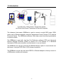
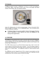
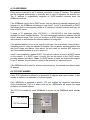
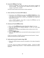
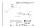
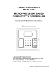
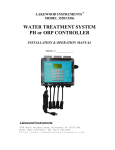
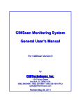
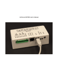
LAKEWOOD INSTRUMENTS
WEBNode
USER’S MANUAL
Lakewood Instruments
7838 North Faulkner Road, Milwaukee, WI 53224 USA
Phone (800) 228-0839 • Fax (414) 355-3508
http://www.lakewoodinstruments.com
Lakewood Instruments
We thank you for your selection and purchase of an Lakewood Instruments product.
Please take the time to read and understand this User’s Manual, paying special
attention to the information about INSTALLATION, OPERATION and TECHNICAL
SUPPORT.
If, in the future, any customer or technical support is required, we strongly
recommend that you contact us for assistance. Our Customer Service Department
is happy to assist you with all your product and information requests.
Lakewood Instruments Customer Service and Technical Support Departments
can be reached by calling (800) 228-0839 or faxing (414) 355-3508, Monday
through Friday, 7:30 a.m. – 5:00 p.m. Central time.
Mail should be sent to:
Lakewood Instruments
7838 North Faulkner Road
Milwaukee, WI 53224 USA
1
2
LAKEWOOD INSTRUMENTS WEBNODE
Table of Contents
1.0 Introduction........................................................................................................... 5
2.0 Features, Benefits and Specifications................................................................... 6
2.1 Features...................................................................................................... 6
2.2 Benefits........................................................................................................ 6
2.3 Specifications............................................................................................. . 6
3.0 Contents................................................................................................................ 7
4.0 Overview ............................................................................................................... 7
4.1 IP Addresses .............................................................................................. 8
4.2 TCP Port Number ....................................................................................... 8
4.3 Network Considerations.............................................................................. 9
5.0 Getting Started................................................................. ..................................... 10
5.1 Software Installation ................................................................................... 11
5.1.1 Installation of .net framework ......................................................... 12
5.1.2 Installation of Com Port Redirector (CPR) ..................................... 12
5.1.3 Installation of Lakewood Remote Windows Software (LRWS)....... 13
5.2 Hardware Installation ................................................................................... 13
5.3 Operation.................................................................................................... 14
5.3.1 Configuring CPR for a New WEBNode Connection....... ................ 14
5.3.1.1 Start CPR ......................................................................... 14
5.3.1.2 CPR Manager Description ................................................ 14
5.3.1.3 Search for Device Servers................................................ 15
5.3.1.4 Refresh View of Com Ports on the System ...................... 16
5.3.1.5 Adding or Removing Com Ports ....................................... 17
5.3.1.6 Configuring Com Ports for WEBNodes............................. 18
5.3.1.7 Exporting to a Com Port Config file .................................. 19
5.3.1.8 Importing from a Com Port Config file .............................. 20
5.3.1.9 Setting Up WEBNode Email/Text Message Alerts............ 21
5.3.1.10 Sending Email as a Text Message ................................. 22
5.3.1.11 The WEBNode Alert Message........................................ 22
5.3.1.12 Verifying the Internet IP Address .................................... 23
5.3.1.13 Controller Communications Settings .............................. 23
6.0 Technical Support ................................................................................................. 24
6.1 Troubleshooting.......................................................................................... 25
7.0 Drawings ............................................................................................................... 27
7.1 WEBNode Installation Drawing 1268970_1a............................................. 28
3
4
1.0 Introduction
Controller with 1 Relay Node, 2 Conductivity Nodes,
and Drum Level Sensor Connected to Personal Computer
The Lakewood Instruments WEBNode is used to connect a model 2000 series -RS2L
option card to Ethernet networks using the Transmission Control Protocol (TCP) and the
IP protocol family. The WEBNode contains a Web (http) server that allows presentation
of custom content.
The WEBNode is used with the Com Port Redirector software (CPR) and Lakewood
Remote Windows Software (LRWS) to access all of the features of a Lakewood
Instruments 2000 series controller over the internet or over an intranet.
The WEBNode can also be used with the EZWeb Wireless option to communicate over
the internet using an EVDO Rev A (3G) wireless connection.
The WEBNode can also be used as an RS232 to Ethernet adapter to directly connect to
a 2000 series controller with a laptop.
5
2.0 Features, Benefits, and Specifications
2.1 Features
The Lakewood Instruments WEBNode is compatible with ALL existing 2000 series
controllers with the -RS2L option.
The WEBNode is Plug and Play, with minimal setup for intranet connections and is
accessable via the internet through pre-assigned ports (with firewall access).
The WEBNode contains built-in web server hardware to prevent network port access by
un-authorized sources.
The configuration of the WEBNode is stored in non-volitile memory and is retained on a
loss of power.
2.2 Benefits
The Lakewood Instruments WEBNode gives you the flexibility to monitor, control, and
receive notices from your 2000e series controllers locally over an TC/IP protocol
Ethernet network or from anywhere in the world via the internet.
The WEBNode removes the RS232 cable length limitations by using Ethernet or TCP/IP
networks.
The WEBNode is a self contained web page that is not hosted by a manufacturer; NO
ACCESS FEES.
The alarms you choose will trigger either a modem based or internet based alert. This
allows for timely response to the site for any specific (user defined) alarm conditions.
2.3 Specifications
Serial Interface
Serial Line Format
Modem Control
Network Interface
Ethernet compatibility
Internal Web Server
Protocols supported
Weight
Temperature
Relative Humidity
Input Power
RS232 with a 19200bps baud rate.
8 data bits, 1 stop bit, and parity of none.
CTS, RTS.
RJ45 Ethernet 10Base-T or 100Base-TX (Auto-Sensing)
Version 2.0/IEEE 802.3
Serves static web pages and JAVA applets
TCP/IP and HTTP
2.2 oz.
Operating Range: -40°C to +85°C (-40°F to 185°F)
Operating: 5% to 95% non-condensing
+9 to +24 VDC
6
3.0 Contents
A WEBNode shipment includes: a WEBNode, a 120 VAC to +9 VDC power adapter, a
25 foot RJ11 cable, a 9-pin DCE connector, and a cd-rom that includes: the LRWS
software, CPR software, and .net Framework software.
Inspect the shipping carton for obvious external damage. Note on the carrier's bill-oflading the extent of the damage, if any, and notify the carrier. Save the shipping carton
until your WEBNode is started up.
If shipping damage has occurred, call the Lakewood Instruments Customer
Service Department at (800) 228-0839 and return the WEBNode to the
factory in the original carton.
4.0 OVERVIEW
The WEBNode is the hardware that is used in conjunction with the Com Port Redirector
software program (CPR) and the Lakewood Instruments Remote Software (LRWS) to
communicate with Lakewood Instruments 2000 series controllers over an intranet or the
internet using TCP/IP protocol.
The LRWS software program is a Windows-based program that is used to access and
control Lakewood Instruments 2000 series controllers. The CPR software program is
used to create and manage virtual com ports, which are redirected over a network to the
serial port of a device server. The WEBNode contains an Internal Network device
server.
The WEBNode uses the Internet Protocol (IP) for network communications and the
Transmission Control Protocol (TCP) to assure that no data is lost or duplicated, and that
everything sent to the connection arrives correctly at the target.
7
4.1 IP ADDRESSES
Every device connected to an IP network must have a unique IP address. This address
can be assigned automatically or manually and is used to reference the specific unit.
The IP address is automatically assigned on DHCP-enabled networks when the
WEBNode boots up.
If the WEBNode cannot find a DHCP server, and you have not manually assigned an IP
address to it, the WEBNode will attempt to use AutoIP. AutoIP is an alternative to DHCP
that allows hosts to automatically obtain an IP address in smaller networks that may not
have a DHCP server.
A range of IP addresses (from 169.254.0.1 to 169.254.255.1) has been explicitly
reserved for AutoIP-enabled devices. The unit automatically selects an address from the
AutoIP reserved range. Then, your unit sends out a (ARP) request to other nodes on the
same network to see whether the selected address is being used.
If the selected address is not in use, then the unit uses it for local subnet communication.
If another device is using the selected IP address, the unit selects another address from
the AutoIP range and reboots. After reboot, the unit sends out another ARP request to
see if the selected address is in use, and so on.
AutoIP is not intended to replace DHCP. The unit will continue to look for a DHCP server
on the network. If a DHCP server is found, the unit will switch to the DHCP serverprovided address and reboot. Note: If a DHCP server is found, but it denies the request
for an IP address, the unit does not attach to the network, but waits and retries.
If the WEBNode will be used for internet communications, the network must have a static
IP address.
4.2 TCP PORT NUMBER
Every TCP connection is defined by a destination IP address and a port number. A port
number is similar to an extension on a phone system.
Each WEBNode is assigned a specific TCP port number by Lakewood Instruments
during manufacture. This is to ensure that no two WEBNode’s will require the same
porting on a common network.
The TCP Port number for each WEBNode is printed on the WEBNode serial number
label.
HW Address
TCP Port Number
8
4.3 NETWORK CONSIDERATIONS
In order for the WEBNode to function via the internet, the site must have four items
resolved.
1) The network or the connection to the network where the WEBNode will reside
must have an Internet Service Provider (ISP) Internet address that is an STATIC
IP address. This requires that the ISP lock down a specific address (Example:
http:\\169.256.23.13) that will provide a consistent address for connection
purposes. Without the STATIC IP, the Lakewood Remote Windows Software
(LRWS) and CPR Programs cannot tunnel through the internet to the controller,
since they will not know where the controller is residing. The installation site may
already have a static IP if they originate their own homepage or use programs
(accounting/sales/engineering) that require field personnel to communicate with
internal systems. If not, the customer’s ISP may set up a STATIC IP connection
for a fee. An alternative to the customer attaching a WEBNode and controller to
their network is to use the EZWEB Wireless system from Lakewood Instruments.
This requires no additional infrastructure to support, but there is a fee to maintain
a wireless Internet connection separate from the customer’s system.
2) The network must have “port forwarding” or “Open porting” for the ports 30718
and an additional port specific to each individual device (found on the serial
number tag). Port forwarded port 30718 is a “tagback” port which allows the
WEBNode programs to handshake with the originating PC before completing the
connection via the secondary port, where the data interchange and RS232
communications packages will be exchanged. The port from the back of the
WEBNode will number from 10001 thru 12000)
3) In order to make changes to the WEBNode webpage from from outside of the
firewall, port 8080 must be opened. It is recommended that port 8080 be closed
after changes are made.
4) In order to send emails or text message outside of the firewall, port 25 outgoing
needs to be opened.
9
5.0 Getting Started
The following procedure summarizes the steps for using a WEBNode to communicate
with a Lakewood Instruments 2000 Series Controller.
Software Installation
1. If not already installed, install .net framework 2.0 on each PC that will communicate
with the WEBNode.
2. Install Com Port Redirector (CPR) on each PC that will communicate with the
WEBNode.
3. Install Lakewood Remote Windows Software (LRWS) on each PC that will
communicate with the WEBNode.
Hardware Installation
1. Connect the 9-pin DCE connector to the WEBNode.
2. Connect one end of the telephone cable to the RJ11 jack on the RS2L card inside the
controller.
3. Connect the other end of the telephone cable to the RJ11 jack on the 9-pin DCE
connector.
4. Connect the WEBNode to the network using an Ethernet cable.
5. Provide power to the WEBNode using the supplied +9vdc power supply.
Operation
1. Start the CPR program.
2. If the WEBNode is attached to an intranet, search for WEBNodes that are connected
to the network. Note the IP addresses and TCP Ports of each WEBNode. If you are
connecting through the internet, you will need to obtain the IP address for each
WEBNode from your IT professional.
3. Add a Com Port for each WEBNode and configure for the IP address and TCP Port
for each WEBNode. The TCP Port number for each WEBNode is assigned at the
factory and is documented on the serial number tag of the WEBNode.
4. Verify the connectivity between Com Port Redirector and each WEBNode.
5. Close the CPR program.
6. Start the LRWS program.
7. Select CONTROLLERS and add a new controller, selecting Internet and using the
Com Port that was configured in CPR for each WEBNode.
8. Connect to the desired controller.
10
5.1 Software Installation
The use of a WEBNode requires that the following software be installed:
.NET Framework
The Microsoft .NET Framework version 2.0 (x64) redistributable package installs the
.NET Framework runtime and associated files required to run 64-bit applications
developed to target the .NET Framework v2.0.
The .NET Framework version 2.0 (x64) improves scalability and performance with
improved caching, application deployment and updating with ClickOnce, support for the
broadest array of browsers and devices with ASP.NET 2.0 controls and services and 64bit support.
Com Port Redirector (CPR)
Com Port Redirector is a software utility for network-enabling software applications that
do not have network support. Com Port Redirector installs virtual communication (COM)
ports, which are redirected over a network to the serial port of a device server. Com Port
Redirector consists of the following modules:
•
CPR Manager enables you to map com ports to device servers, configure, and
test com ports.
•
CPR Monitor enables you to identify and troubleshoot problems.
Lakewood Remote Windows Software (LRWS)
Lakewood Remote is a Windows-based program that accesses all the features of
Lakewood 2000 Series controllers remotely. Communication is direct-connect via RS232 or remotely over phone lines with a modem. A user-selectable password is required
to access any feature beyond viewing.
Lakewood Remote allows access to multiple controllers, phone numbers and passwords.
Using standard Windows-format mouse-click buttons, all features of the controller can be
accessed. The datalog stored in the controller can be downloaded into a commadelimited file. This can be used by Lakewood Graph or imported into other applications,
such as spreadsheets.
11
5.1.1 Installation of .net framework
Com Port Redirector (CPR) requires the installation of the .net framework program in
order to function. You may not need to install the .net framework program on your PC
because it may already be installed . A quick way to tell if you need to install the .net
framework program is to try to install the CPR program. If the .net framework program is
not already installed on your PC the CPR program will fail to install.
System Requirements
Supported Operating Systems: Windows Server 2003, Datacenter x64 Edition;
Windows Server 2003, Enterprise x64 Edition; Windows Server 2003, Standard x64
Edition; Windows XP 64-bit
Required Software:
Windows Installer 3.0 is required. Windows Installer 3.1 or later is recommended.
IE 5.01 or later: You must also be running Microsoft Internet Explorer 5.01 or later for all
installations of the .NET Framework.
Disk Space Requirements: 280 MB (x86), 610 MB (x64)
Important: Make sure you have the latest service pack and critical updates for the
version of Windows that you are running. To find recent security updates, visit Windows
Update.
Installation
With your Lakewood Remote disk in your CD-rom drive, browse to the dot net framework
folder on the LRWS CD rom.
Double click on the dotnetfx application. This will install .NET Framework.
5.1.2 Installation of Com Port Redirector (CPR)
System Requirements
Supported Operating Systems: Windows 2000, 2000 Server, XP, 2003 Server, or
Vista.
Required Software: Microsoft .NET Framework v2.0.
30MB free hard drive space.
Installation
With your Lakewood Remote disk in your CD-rom drive, browse to the Com Port
Redirector folder on the LRWS CD rom.
Doubleclick on the the Setup application. This will install CprDotNetCDGen4.1.1.3.
The application installation directory defaults to C:\Program Files\CPR, unless another
folder is selected during the installation process.
A shortcut to this application is created on the Start/Programs menu for CPR Manager
and CPR Monitor.
12
5.1.3 Installation of Lakewood Remote Windows Software (LRWS)
System Requirements
Supported Operating Systems: Windows 2000, 2000 Server, XP, 2003 Server, or
Vista.
30MB free hard drive space.
INSTALLATION
With your Lakewood Remote disk in your CD-rom drive, browse to the LRWS folder and
unzip the LRWS application.
After you have unzipped LRWS, run the application install.exe and follow the prompts.
Refer to the LRWS manual for additional information on the installation of the LRWS
software.
5.2 Hardware Installation
Hardware installation consists of connecting the WEBNode to the 2000 series controller,
connecting the WEBNode to the network, and connecting the WEBNode to a power
supply.
The network can be an intranet connection, a direct connection to a computer via an
Ethernet jack, or a connection to an EZWEB Wireless system.
The WEBNode is supplied with a 9-pin DCE connector, a 25-ft telephone cable with
RJ11 jacks, and a 120vac to +9vdc power supply.
An Ethernet cable is required and is not supplied with the WEBNode. If you are going to
direct connect to your computer's Ethernet port, and your Ethernet port is not a multi-plex
port, you will need to use a cross-over Ethernet cable.
INSTALLATION
Connect the 9-pin DCE connector to the WEBNode.
Connect the 25-ft telephone cale between the 9-pin DCE connector and the RS2L card
located inside the 2000 series controller.
Connect an Ethernet cable between the WEBNode and a network jack.
Connect the +9vdc power supply to the WEBNode and plug the power supply into a
120vac wall outlet.
The WEBNode has indicator lights on the Ethernet jack to indicate the transmission of
data.
13
5.3 Operation
5.3.1 Configuring CPR for a new WEBNode connection
The WEBNode is pre-configured at the factory for operation with the Lakewood
Instruments 2000 series controllers. The set up of CPR consists of adding com ports,
and entering the IP addresses and TCP ports for each WEBNode.
5.3.1.1 Start CPR
Click on START
Select CPR
Select CPR
Manager
5.3.1.2 CPR Manager Description
The CPR Manager screen is divided into three sections: the left pane shows a tree
structure of all com ports that are currently configured, the right pane shows information
about all the com ports that are shown in the left pane and is used to configure a
selected com port, and the bottom section is used to show a list of device servers with
their address information currently on the local network. The bottom section can be
hidden or displayed at the users discretion.
14
When "ALL COM PORTS" is selected in the left pane, the Com Port List tab in the right
pane lists the existing com ports along with any additional information, if available, such
as the IP address of the device server to which the com port is connected, and the TCP
port of the device server to which the com port is connected (for example, 10001).
When a single com port is selected in the left pane, the right pane will show the current
setting of that com port and will allow the user to change these settings.
The list of internal device servers is displayed by clicking on the magnifying glass
the upper left-hand corner of the screen.
in
5.3.1.3 Search for Device Servers
Use the search feature to list the device servers currently on your internal network.
To list device servers:
1. Click the Search icon
.
A list of device servers on the local network displays in the bottom pane of the
window.
2. View the following information about the device server, if available:
IP Address - Internal IP address of the device server to which the com port is
connected.
TCP Port - The TCP Port Address assigned at the factory.
Device Name - A user-supplied name that identifies the device server.
Port Name - A user-supplied name that identifies the port.
HW Address - Hardware address (also called MAC or Ethernet address) that identifies
the unit. It is written on the WEBNode label, in the format: 00-20-4a-XX-XX-XX,
where the XXs are unique numbers assigned to the WEBNode.
The HW Address can be used to help identify WEBNodes.
To name a device server and port:
1. In the Device pane, right-click in the device's row. A pop-up menu displays.
2. Select Name Device and Port. The Change Names dialog box displays.
3. Enter the Device Name and Port Name and click OK.
15
WARNING: IT IS HIGHLY RECOMMENDED THAT YOU REFRESH VIEW OF COM
PORTS ON THE SYSTEM BEFORE MAKING ANY CHANGES TO THE CURRENT
CPR CONFIGURATIONS, OR PROGRAM CONFLICTS/DAMAGE TO PROGRAMS
MAY OCCUR.
5.3.1.4 Refresh View of Com Ports on the System
Some programs may reserve some com ports for their own use and if these programs
are opened after CPR is opened but before making changes to the CPR configurations
program conflicts and/or damage to programs may occur.
To refresh view of com ports on the system:
1. Click on COM PORT in the CPR header.
2. Click on Refresh View of Com Ports on the System.
3. The current view of the Com Ports will be refreshed and changes to the com port
configurations can be safely made.
16
5.3.1.5 Adding or Removing Com Ports
CPR enables the user to create up to 256 virtual com ports. Only the first 252 com ports
can be used with the LRWS software. Some com ports will be listed as "Inaccessible"
and are greyed out. This means that these com ports are already in use by other parts
of your computer system and cannot be used by CPR.
To add or remove a com port:
1. Click the Add or Remove icon
, or select Add and Remove from the Com Port
menu. A window displaying a list of numbered com ports opens. Com Ports are
added by checking their boxes and removed by unchecking their boxes. Com ports
with check marks have already been added.
2. Do one of the following:
To select com ports individually, select the appropriate checkboxes.
To add a range of com ports, enter the beginning and end of the range to the right
of the Check (Range) button and click the Check (Range) button.
To remove a range of com ports, enter the beginning and end of the range to the
right of the Uncheck (Range) button and click the Uncheck (Range) button.
To select all of the com ports, click the Select All button.
To clear all checkboxes, click the Select None button.
3. Click the OK button. The dialog box closes. The added com ports display in red and
are identified as new. The word "Modified" displays at the bottom of the window.
Removed com ports that were saved previously have "marked for deletion." beside
their names.
4. To save the settings, click the Save icon
17
5.3.1.6 CONFIGURING COM PORTS FOR WEBNodes
You must configure a new com port before it can be used by the LRWS software. A
separate Com Port is used for each WEBNode.
To configure com port settings:
1. Click the desired com port in the tree structure in the left pane. Select the Settings
tab in the right pane.
Select Com Port
Select Settings Tab
Enter Com Port
Information
2. Enter the following information:
The Host - This is the IP address for the WEBNode. This is the internal IP
address if the WEBNode will be accessed over an intranet or this is the
static IP address if the WEBNode will be accessed over the internet.
NOTE: If your computer will be used to access this WEBNode over the
internet and over the local network, enter the internal IP address as the first
host then enter the internet IP address as the second host. CPR will try
each in succession to access the WEBNode.
The TCP Port - This is the TCP Port address that is assigned to the WEBNode at
the factory.
3. To save the port settings, click the Save icon
.
Once the com port information is entered, Com Port Redirector can be closed and will
not need to be opened again unless you are adding or removing com ports or changing
comport settings.
18
5.3.1.7 EXPORTING TO A COM PORT CONFIG FILE
Your current CPR com port configurations can be exported to a file for sharing on
another computer or for archiving purposes. This makes it easy to import your com port
configurations to another computer running CPR.
To export to a com port config file:
3. Click on COM PORT in the CPR header.
4. Click on Export to Com Port Config File.
3. Save the file as a Com Port Config file.
19
5.3.1.8 IMPORTING FROM A COM PORT CONFIG FILE
Your current CPR com port configurations can be imported from a file. This makes it
easy to import your com port configurations to another computer running CPR.
To import to a com port config file:
1. Click on COM PORT in the CPR header.
2. Click on Import from Com Port Config File.
3. Select the Com Port Config file you wish to import.
4. To save the port settings, click the Save icon
20
.
5.3.1.9 SETTING UP WEBNode EMAIL/TEXT MESSAGE ALERTS
The 2000 series controllers have the ability to "call-out" on user selected alarm
conditions. These call-outs can be in the form of e-mail or text messages with the use of
the WEBNode. No customer email server or SMTP access is required and no additional
set-up is required for this function to operate. The WEBNode can be custom configured
to use SITE specific email servers. Contact Lakewood Instruments for additional
information.
The WEBNode ALERT setup screen for the WEBNode is located on the WEBNode
homepage and can be accessed by using your web browser. This homepage is the IP
address of the WEBNode followed by ":8080". For example: http://168.24.1.14:8080.
The homepage contains links to the Lakewood Instruments products pages as well as
tables for contact information in case of an alarm.
To set up the WEBNode for email and text message alerts:
1. Access the WEBNode ALERT screen for the WEBNode by using your web browser to
access device homepage. This home page is the IP address followed by ":8080".
For example: http://168.24.1.14:8080.
2. Click on the "Use WEBNode Alert when Controller in Alarm" check box.
3. Enter the email and text message addresses to which you want alarm notifications to
be sent.
4. Enter the alarm message you want displayed when an alarm occurs for this controller.
5. Click the UPDATE button.
6. Click on the TEST ALERT button and verify that the alarm message is sent to all
addresses.
In order for the unit to send the alert, internet access for the network connection that is
home to the WEBNode must be established. It is possible that the email alert may not
be sent if the network has blocked port 25 or common sites like MSN or Yahoo.
21
5.3.1.10 Sending Email as a Text Message
The WEBNode Alert email can be sent as a text message to a cell phone. The major US
cellular carriers use the [email protected]_domain.com format for text
capable cell phones, with a limit of 160 characters in the subject and message body
(total). For example: [email protected].
See the table below for some common cell carrier domains that are used in the USA.
Carrier
Send Email to phonenumber@....
Alltel
@message.alltel.com
AT&T
@mms.att.net
Nextel
@messaging.nextel.com
Sprint
@messaging.sprintpcs.com
SunCom
@tms.suncom.com
T-mobile
@tmomail.net
VoiceStream
@voicestream.net
Verizon
@vtext.com
5.3.1.11 The WEBNode Alert Message
The WEBNode Alert message is an email message that can be sent to up to six email or
text message addresses. The message can be up to 80 characters in length. It is
recommended that your message include some kind of an identifier for the controller.
For example: CUSTA, Cooling B is in alarm. 79.45.56.777
In this example, we identified the customer, the tower, the status, and the IP address.
The email notification will come from [email protected], have a
subject line of WebNode Alert, and will look something like:
22
5.3.1.12 Verifying the Internet IP Address
The WEBNode webpage includes a link to verify your internet IP address. At the bottom
of the webpage is the CHECK YOUR ISP link. With a computer that is connected to the
same network as the WEBNode, click on this link to verify your internet IP address. The
IP address that will be shown is the address you would use to access your WEBNode
from outside your firewall over the internet.
5.3.1.13 Controller Communications Settings
The WEBNode is configured to communicate with your Lakewood Instruments 2000
series controller via RS232 with the following settings:
Baud Rate
Data Bits
Parity
Stop Bits
19200
8
NONE
1
Your controller must have these settings in the communications screen in order to
communicate with a WEBNode.
23
6.0 Technical Support
If you need technical support for your Lakewood Remote Windows Software:
Lakewood Instruments Technical Support for the LRWS software and related
products can be reached by calling (800) 228-0839 or faxing (414) 355-3508,
Monday through Friday, 7:30 a.m. – 5:00 p.m. Central time.
NOTE: IF YOU CALL FOR TROUBLESHOOTING HELP, PLEASE MAKE SURE
THAT THE MODEL NUMBER, SERIAL NUMBERS AND ANY INFORMATION
ABOUT OPTIONS ARE ALL READILY AVAILABLE FOR REFERENCE.
Mail and returns should be sent to:
Lakewood Instruments
7838 North Faulkner Road
Milwaukee, WI 53224 USA
When any merchandise is returned to the factory, please call and obtain a return
goods authorization order (RGA) number and have the following information
available:
•
•
•
•
•
Customer’s name, address, phone and fax numbers (shipping and billing).
A hard copy purchase order number (no exceptions) for cases where repairs or parts are
required that are not under warranty.
A contact person’s name and phone number to call if the equipment is beyond repair or
to discuss any other warranty matter.
Equipment model and serial numbers.
Reason for return, e.g., repair, warranty, incorrect part, etc.
We will then fax to your attention an RGA form that must accompany the returned item.
NOTE: THE RGA NUMBER MUST BE CLEARLY WRITTEN ON THE OUTSIDE OF THE
PACKAGE(S) BEING RETURNED.
ANY ITEMS SENT BACK TO THE FACTORY
WITHOUT AN RGA NUMBER WILL BE REFUSED
AND RETURNED TO SENDER
24
6.1 Troubleshooting
Here is a sequence of steps that should be performed to troubleshoot the WEBNode. For
additional troubleshooting of LRWS please refer to the LRWS manual.
You can test your LRWS and CPR software on one of our Controllers here at Lakewood
Instruments. The internet address is 75.19.65.62. The TCP port is 10001. Set up CPR
with this address and try to connect using LRWS.
6.1.1 Troubleshooting Steps
If a connection issue should occur, it is recommended that troubleshooting be performed
at the local network where the WEBNode resides.
A. Test a com port connection to a WEBNode:
1. Open CPR.
2. Select the com port in the left pane and click the Com Tests tab in right pane.
3. To open a connection, click the Open button. The current Com Status displays
to the right of the Open/Close button. The com port attempts to connect to the
first host server on the Settings tab for the selected Com Port. If the connection
succeeds, Network Status displays the current status between CPR and the
WEBNode. (This should say Connected to the IP address and TCP port of your
WEBNode i.e.: 192.168.1.55:10001.)
4. The bottom left corner of the screen shows the status of the com port. If there is
an error connecting to the WEBNode there will be a message that states "Status
of Com Port xxx is in Error and Disconnected". If CPR connects to the
WEBNode the message will read "Status of Com Port xxx is Open and
Connected to 192.168.1.55:10001".
5. The bottom right corner of the screen shows that the OPEN/CLOSE test is
running.
If the above test fails:
1.
2.
3.
4.
5.
6.
7.
Verify that the correct IP address has been entered.
Verify that the correct TCP Port has been entered.
Verify that the address assigned to the WEBNode is not already in use.
Verify wiring connections.
Verify that the WEBNode has power.
Try removing power from the WEBNode then restoring power to the WEBNode.
Contact Lakewood Instruments for further troubleshooting help.
25
B. Access the WEBNode Front Page
1. Access the WEBNode front page by using your web browser to access the
device homepage. This home page is the IP address followed by ":8080". For
example: http://168.24.1.14:8080.
If this fails contact Lakewood Instruments for further assistance.
C. Check and Verify Your Internet ISP IP Address
1. At the bottom of the WEBNode front page is the CHECK YOUR ISP link. Click
on this link to verify your internet IP address. The IP address that will be shown
is the address you would use to access your WEBNode from outside your
firewall over the internet.
Is this a STATIC address? To be able to access the WEBNode over the
internet, a static address is required.
D. Activate and Test the WEBNode Alert
1. Click on the "Use WEBNode Alert when Controller in Alarm" check box.
2. Enter the email and text message addresses to which you want alarm
notifications to be sent.
3. Enter the alarm message you want displayed when an alarm occurs for this
controller.
4. Click the UPDATE button.
5. Click on the TEST ALERT button and verify that the alarm message is sent to all
addresses.
If PORT 25 is blocked or if YAHOO is blocked this function will not work. Contact
Lakewood Instruments for further assistance.
E. Set Up and Access the Controller Using LRWS
1. Refer to the LRWS instruction manual for information on the setup and operation
of LRWS.
If this fails, verify the controller communications settings. Consult the LRWS
manual for troubleshooting information. Contact Lakewood Instruments for further
assistance.
26
7.0 Drawings
27
29
For more information call toll free in the USA (800) 228-0839
Manufactured in the USA
Lakewood Instruments
7838 North Faulkner Road, Milwaukee, WI 53224 USA
Phone (414) 355-2807 • Fax (414) 355-3508
http://www.lakewoodinstruments.com