1
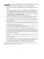
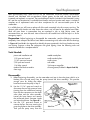
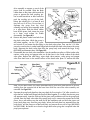
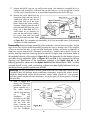
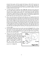
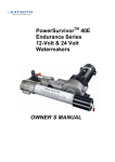
PowerSurvivorTM 80E 12-Volt & 24-Volt Watermakers OWNER’S MANUAL Thank you… …for purchasing a Katadyn PowerSurvivor 80E watermaker. It was built to rigorous specifications, and designed to produce potable freshwater from clean seawater using minimal power. It is simple to install and operate and, with reasonable care and maintenance, will provide years of useful service. Please… …before installing or operating your watermaker, take the short time needed to read this User’s Manual in its entirety. This small investment of time will help assure many years of trouble-free operation from your system. We’ve worked hard to provide you with a reliable product that is affordable, compact, simple to operate and easy to maintain—the rest is up to you. Contact us: Be sure to fill in the enclosed warranty card and return it to us as soon as possible. This is required to fulfill the terms of your warranty. For Customer Service, or information about this and other products from Katadyn, please use our toll-free phone numbers or visit our website at www.katadyn.com. Katadyn North America 4830 Azelia Avenue North Minneapolis MN 55429 Phone: Fax: Website: 800-755-6701 or 763-746-3500 800-548-0406 or 763-746-3540 www.katadyn.com Customer Service / Technical Support: 800-755-6701 or 763-746-3500 (International Collect Calls Accepted) Email: [email protected] We suggest you keep a record of your Katadyn dealer’s name, contact information, and the serial number of your watermaker in the space below: Dealer Name: _________________________________________________________________ Address: _________________________________________________________________ Phone/Fax/Website: _________________________________________________________________ Serial Number: _________________________________________________________________ 2 Table of Contents System Description ................................................................................................................................... 4 Product Specifications ............................................................................................................................. 5 Energy Recovery ....................................................................................................................................... 6 Installation.................................................................................................................................................. 7 Installation DOs................................................................................................................................................. 7 Installation DON’Ts .......................................................................................................................................... 7 Installation Procedures .................................................................................................................................... 8 Using your Watermaker...................................................................................................................... 10 Special Conditions .......................................................................................................................................... 12 Maintenance and Service .................................................................................................................... 13 Pump Maintenance ........................................................................................................................................ 13 Prefilter Maintenance..................................................................................................................................... 14 Membrane Storage, Preserving & Cleaning ............................................................................................. 15 Seal Replacement ........................................................................................................................................... 18 Drive Maintenance ......................................................................................................................................... 24 Troubleshooting Flowchart ........................................................................................................................... 26 Appendix .................................................................................................................................................. 27 Glossary ........................................................................................................................................................... 27 Diagrams .......................................................................................................................................................... 28 Kits & Accessories........................................................................................................................................... 33 Service Log ....................................................................................................................................................... 34 WARRANTY ..................................................................................................................................................... 35 3 System Description The Katadyn PowerSurvivor 80E watermaker system has several components. Refer to the System Diagram (Figure A-1) in the Appendix for an overview of the components of the system and their interconnections. Motor/Drive/Pump & Membrane Housing: At the heart of the watermaker system is a high-pressure, positive-displacement pump. The pump is powered by a reliable 12 (or 24) VDC electric motor. A grease lubricated gearbox (drive assembly) converts the rotary motion of the electric motor to a powerful, reciprocating, linear motion for driving the pump piston. The pump pressurizes input seawater to approximately 800 psi (pounds per square inch) and forces product freshwater through a semipermeable membrane located in the membrane housing. The motor, gearbox and pump have been integrated into a single, compact piece of equipment — with low power consumption, quiet operation and a small footprint. The membrane assembly is a separate unit which allows it to be mounted in a convenient location. Prefilter Assembly: The prefilter assembly consists of one prefilter housing and a standard 30-micron prefilter element constructed of polyester fibers. Two standard elements ship with each system. In some exceptional circumstances, an optional second prefilter assembly with a 5-micron prefilter element may be needed (see Kits & Accessories). The prefilter assembly is separate unit which allows it to be installed in a convenient and accessible location. Valves: Two high-quality plastic 3-way valves are supplied. The prefilter 3-way valve selects between two input sources for the prefilter assembly (and pump): Clean seawater during normal operation An alternate intake line for inputting membrane preservative or a cleaning solution The product 3-way valve allows easy selection between the two required destinations for the product freshwater: A freshwater collection tank for normal operation A convenient drain location for testing and discarding product freshwater, membrane preservative and cleaners Hoses and Hardware: Each PowerSurvivor 80E watermaker is shipped with appropriate hoses and hardware sufficient to perform a normal installation. This includes two high-pressure hoses (3’ and 5’) for carrying pressurized seawater from the pump to the membrane housing and reject brine water from the membrane housing back to the pump. The 1/2" I.D. reinforced plastic hose is used for seawater intake and reject brine. The smaller, 1/4" I.D. clear plastic hose is for routing product freshwater. There are also hose clamps and mounting bracket hardware for the prefilter assembly and membrane housing, and a TDS (Total Dissolved Solids) meter for testing and monitoring the quality of product freshwater. Customer-supplied Equipment: Every installation represents a unique challenge! You or your installer will need to provide: a reliable source of clean seawater for input to the prefilter 3-way valve plumbing to an appropriate drain location for the reject brine water a plumbing solution for your freshwater collection tank Our Promise: Every Katadyn PowerSurvivor 80E watermaker includes a three-year factory warranty and a long history of outstanding customer support. 4 Product Specifications Power Requirements: Construction: Configuration: Rate of Water Production: Feed Water Flow Rate: Pump Weight: Pump Height: Pump Length: Pump Width: Membrane Housing Dimensions: Prefilter Housing Dimensions: 8 amps @ 12 VDC; 5 amps @ 24 VDC* 316 Stainless Steel Pump Housing Modular 3.4 U.S. gal./hr. (12.9 liters/hr.) ±15% @ 13.8 VDC 34 U.S. gal./hr. (129 liters/hr.) 34 lbs. (15.4 kg.) 6.2" (15.7 cm.) 17.5" (44.5 cm.) 13.5" (34.3 cm.) 31" x 2.5" (79 cm. x 6.4 cm.) 12" x 6" (30 cm. x 15 cm.) * The electric current requirement is an average figure. Instantaneous current will vary during a complete cycle of the pump. 5 Energy Recovery The technology behind Katadyn reverse osmosis watermakers Reverse osmosis desalination was first developed in the mid 1950’s. It was a major breakthrough in desalting technology, but the original process required a lot of power. By recovering 90% of the energy lost in conventional reverse osmosis systems, we’ve made small desalinators practical, so you can have freshwater when and where you need it. Conventional Reverse Osmosis Desalination The lower left portion of Figure 2 shows the basic principle of reverse osmosis desalination. When saltwater is forced through a semipermeable membrane at high enough pressure—typically 800 psi—pure water will pass through the membrane, but salts will not. The membrane acts as a barrier to contaminants such as salts, viruses and bacteria, separating them from the pure water. When seawater is forced against a membrane, only 10% passes through as pure water. In a conventional system, the remaining waste brine stream, still under high pressure, passes through a pressure-reducing valve and is discharged overboard. For every gallon of pure water made, up to ten gallons of seawater must be pressurized! Therefore, 90% of the energy used in conventional reverse osmosis is lost! Energy Recovery Makes It Possible The upper right portion of Figure 2 illustrates how Katadyn systems are configured to recover and effectively re-use the energy wasted in conventional reverse osmosis. The waste brine stream contains up to 90% of the energy expended. By recovering this energy, we are able to dramatically reduce the power needed to desalt seawater. To do this, we developed and patented a high pressure energy recovery pump. It recycles the highpressure brine by redirecting it to the backside of the pump’s piston. By balancing the opposing force on the piston’s front side, the brine provides a power assist to the pumping operation. Seawater can then be pressurized with much less effort. Katadyn Watermakers Katadyn watermakers are simple, energy efficient and easy to use and maintain. The PowerSurvivor 80E incorporates the latest advances in watermaker technology, featuring an improved grease lubricated drive assembly, an all-316 stainless steel pump body, and simplified construction for easier and less frequent maintenance. 6 Installation Do it right the first time and reap the rewards The PowerSurvivor 80E watermaker utilizes a low-volume, high-pressure, positive displacement pump. Unlike the centrifugal pumps found in some systems, a positive displacement pump is selfpriming. This pump’s powerful performance enables the delivery of seawater even if the desalinator is mounted several feet above waterline. We still however recommend the use of an additional pump (available in the “silt reduction kit”) for assembly and use of the desalinator above waterline or when a longer hose is required. The most important part of a good installation is proper planning. Although the design and operating requirements of the PowerSurvivor 80E allow much latitude for equipment location, there are several cautions and suggestions you should consider before proceeding with an installation. Installation DOs When choosing a location for the watermaker drive/pump or membrane assembly: Avoid areas with excessive heat. Ambient temperatures above 105° F (40° C) exceed the ratings for the electric motor, and excessive heat can damage or destroy the membrane. (Note: Most engine rooms get hotter than 105° F!) Choose a dry area. The motor/drive assembly is not waterproof and can corrode. Choose an area free of fuel vapors. The electric motor is not vapor-proof and should not be operated if explosive or flammable materials are present! Find a location which allows comfortable access for routine inspection and servicing. In addition, you should: Install the pre filter assembly in an easily accessible location. It needs regular (sometimes daily) inspection and maintenance. For ease of routine maintenance, the choice for this location is probably the single most important decision you will make—plan it carefully! Provide a shutoff valve or seacock in the seawater intake line. Install a coarse strainer in the seawater intake line. We recommend using properly sized ring terminals and a terminal strip near the pump to connect electric power. This allows for easy testing, removal and servicing when required. Installation DON’Ts Don’t use a thru-hull installed high on your vessel’s hull for your source of seawater intake. This is especially important for sailboats. Even a normal amount of heel when under sail can cause the thru-hull to be out of the water, allowing air into the intake system. A rolling anchorage can do the same. Don’t locate the pump assembly above gear or materials that could be damaged if it leaked. Don’t locate the pump assembly near to sleeping quarters, bunks, or other areas that are normally “quiet” areas for yourself or crew members. 7 Installation Procedures Although every installation has its custom aspects, the following general instructions should be useful to the typical installer. Refer to Figure A-1 (in the Appendix) for information on part identification and system connections. 1. Install Pump: After reading the comments on the preceding pages, decide on a location for the pump and drive assembly. It should be mounted with the pump and drive side by side horizontally. The reason for this requirement is to avoid two problems: If the pump develops a seawater leak and is located directly above the drive assembly, the drive assembly and/or electric motor may be damaged (Figure 3, left). If the drive assembly develops an oil leak and is located directly above the pump, oil may find its way into the pumping system and damage the membrane (Figure 3, right). We recommend securely thru-bolting the pump/drive assembly to a sturdy bulkhead or platform, using corrosion-resistant 1/4" fasteners with flat washers (See Figure A-1). Pick a location that allows ample space for routing the required hoses and electrical wires to the pump and motor. 2. Connect Electrical Power to Pump: Basic Electrical Diagram To provide 12 (or 24) VDC electric power to the motor, use a minimum of 14 gauge (2.5 mm2) / 12 VDC (16 gauge (1.5 mm2) / 24 VDC) stranded copper wire. We recommend 12 gauge (4 mm2) / 12 VDC (14 gauge (2.5 mm2) / 24 VDC) or larger wire for distances over 20 feet (6 m). Tinned, stranded copper wire is preferred for marine installations and is available in most marine hardware stores. Figure 4 shows a typical electrical power configuration. Fuse and Circuit Breaker: 12 V = 15 A Terminal 24 V = 10 A Strip white red black + 3. Mount Pre filter Assembly and 3-Way Valve: Lightly coat the male threads - black M Dimension of the cable: 14 gauge (2.5 mm2) / 12 V 16 gauge (1.5 mm2) / 24 V 12 V or 24 V Battery or Power Source Figure 4 of the middle port of the pre filter 3-way valve with a non-hardening, paste-type thread sealant (e.g., Loctite 5331, Permatex®) to assure an airtight seal. (Note: Teflon tape is not recommended.) 1. Carefully thread the middle port of the pre filter 3-way valve into the “IN” port of the pre filter housing. Do not over tighten this connection. When assembled correctly, the long axis of the 3-way valve should be vertical (See Figure A-1). 2. Fasten the supplied right-angled mounting bracket for the pre filter assembly to a bulkhead. Ideally, it should be lower than the pump intake to allow air bubbles to pass easily. Orient it so the pre filter assembly will be vertical, with the bowl underneath. We recommend that it be thru-bolted with corrosion-resistant hardware. 8 3. Screw the top of the pre filter housing to the bracket with the supplied screws. One port of the pre filter 3-way valve should project above the housing through the notch in the mounting bracket. 4. Install Seawater Intake Plumbing: There are two common approaches to providing the seawater intake circuit: Tee into an existing seawater intake (e.g., engine cooling water or manual seawater pump inlet). Install a dedicated thru-hull for the watermaker. Either of these configurations should meet the following criteria: It should be at a low point on the vessel’s hull, to minimize the chance of air intake during heeling or rough conditions. The thru-hull should be a minimum of 1/2" I.D., and possibly larger if it is a shared inlet. (Note: If there is the possibility that in the future you will want to upgrade by adding a second PowerSurvivor 80E to implement redundant systems—you should consider substituting 5/8" I.D. hoses and hose fittings during your initial installation). An easy-to-reach seacock should be installed on the thru-hull immediately inside the hull. A coarse seawater strainer is strongly recommended. It should be easy to reach and clean. The easiest and most commonly used approach is to tee into an existing seawater intake system. Because the flow rate and volume of seawater intake for the PowerSurvivor 80E are both extremely low, the pump can be adequately supplied by most pre-existing intakes—even inlets that operate at modest negative pressures, such as the cooling water inlet for an engine or generator. When teeing into an existing seawater supply, we recommend installing a separate seacock or valve (in addition to the one at the thru-hull) to independently control the supply to the watermaker. 5. Install Reject Brine Plumbing: The reject brine water can be teed into an existing scupper or sink drain hose for draining overboard. Use the 1/2" reinforced hose and supplied hose clamps. A tee of the correct size will have to be supplied. Alternatively, a dedicated thru-hull may be installed at a convenient location. In this case, we recommend that a seacock be installed at the thru-hull. 6. Install Product Freshwater Plumbing: Your product freshwater plumbing design should allow for both saving and discarding of product freshwater. This normally requires (1) a container for collecting good product freshwater and (2) a drain location. In no case should the product freshwater hose be permanently plumbed into the ship’s potable water storage tank(s), without providing a way to reject the product freshwater when necessary. Note that product freshwater should always be rejected during the first few minutes after startup, and especially after treating with membrane preservative or chemical cleaners. For that reason alone, a means must be provided for disposing of unwanted product freshwater. In general, we do not recommend that the output of product freshwater be routed directly into a vessel’s freshwater storage tank(s). If for any reason the watermaker should fail during operation, there is a good chance that the entire supply of freshwater in the storage tank could become contaminated by unpurified seawater. This is especially important if: you have only a single tank for storing potable water. you will be making extended offshore passages and depend on your watermaker for your potable water supply. 9 The preferred method for collecting product freshwater is to use portable jerry jugs or a separate “day tank,” which is isolated from the main storage tank. Some method should be devised for testing the product freshwater quality at the beginning and at the end of each operation. When you are certain that the quality of the collected product freshwater is acceptable, it can be transferred to the main storage tank. Note: The important concept is to always have a minimum quantity of known-good potable water available at all times, either in your main storage tank or in the collection container(s). The length of your expected voyage and maximum distance from a source of potable water will determine the size of the adequate minimum amount. Arrange your watermaking schedule to assure that you always have the minimum of known-good potable water on board in one or both of your containers. To route the product freshwater output of their watermakers, many users simply run the 1/4" I.D. clear plastic hose directly from the output hose barb on the membrane housing to a single location, where the water is tested and either discarded or run into a collection container. Should you prefer to have your product freshwater output routed to two separate locations for testing/discarding and collection, the watermaker system includes a product 3-way valve for use in your output plumbing. Refer to Figure A-1 for a routing diagram. Using your Watermaker Watermakers like to be run often The ease of operation of our watermakers has its roots in our original products, which were designed as military-quality survival equipment. Our deep experience in this technology, combined with many years of active user feedback, allowed us to design a watermaker that can be operated with little or no technical knowledge. There are no complicated adjustments to make or gauges to monitor. By following the instructions below and paying attention to system maintenance, you can expect years of trouble-free operation. Pre-Run Checklist: Before running your watermaker, always check the following: Check for bad (“rotten egg”) smell from the water in the prefilter assembly. Replace the element and clean the housing, as required. Also check for foul water in any in-line coarse strainer. Any valves in the seawater intake, reject brine and product freshwater lines should be open. The prefilter 3-way valve should be in the position to intake seawater. Assure that the product freshwater output is routed to a drain for testing/discarding. Make sure the clean/run valve lever on the pump is in the “run” position (See Figure 5). Check battery or power supply voltage. Operating your watermaker below about 11 VDC is hard on the electric motor and dramatically reduces the output of product freshwater. Observe the seawater around your vessel. Is it clean enough to use for your seawater intake? There are several things to avoid feeding to your watermaker: 10 • • • • petroleum products, such as oil, fuel, thinners, paints, paint removers, etc. chlorine-treated water (for example, most “dockside” water) silty water—water contaminated by fine, hard, suspended particulates putrid water, “red tides”, or any seawater that smells or looks contaminated It is important to remember that the watermaker is designed to process clean, open-ocean seawater. Any departure from that standard for your seawater intake runs the risk of causing excessive wear or damage to internal pump parts and/or the vulnerable reverse osmosis membrane, or producing contaminated product freshwater. Note: Judging the quality of seawater input always involves a certain calculated risk. We know of watermaker systems that have been destroyed far offshore by intaking fresh whale excrement or oil contaminants from natural seepages—still, the chance of such things happening is normally small. On the other hand, regularly running a watermaker in an enclosed marina or harbor runs a much higher risk of harmful contamination. If you need to test a new installation while in a marina or harbor, monitor the water quality around your vessel carefully while testing. Most of the time you should be able to run the watermaker safely for enough time to check out the system. Don’t sail away without testing a new installation or repair! Startup: Turn on the electric power to the watermaker. If there is air in the seawater intake plumbing, the pump may require several minutes to draw up enough water to fill the hoses, prefilter housing, pump and membrane housing. Since the pump is self-priming, there is no need to prime the system prior to running. Shortly after the hoses and prefilter housing have filled with seawater, reject brine water should start discharging from the pump. Test and Run: When all air has been forced out of the system (which may take several minutes more), product freshwater should begin to flow from the hose barb at the end of the membrane housing. It is normal for product water to be unpotable for a short time after startup. Reject the initial product water and use the TDS meter and/or taste test to monitor the quality until it is acceptable. This will usually take about 5–10 minutes. When good quality water is flowing continuously, direct the product freshwater output to your freshwater collection tank. Continue to run until the desired quantity of water has been produced. Shutdown and Storage: When the desired amount of water has been produced, the product freshwater quality should be checked again. If water quality is good at both the beginning and end of the run, it is likely that the collected water is good and can be safely transferred to the ship’s potable water storage tank. If you plan to run the watermaker again within a couple of days, it can simply be turned off. If you do not intend to use your watermaker again within a week, it should be treated with membrane preservative to prevent organic growth on the membrane. Note: Organic growth is much more rapid in warm or tropical climates. If using the watermaker in a tropical environment, we recommend a membrane preservative treatment if the watermaker will not be run again within the next three days! Before doing repairs or maintenance work on a PowerSurvivor, close the seawater inlet valve after turning off the system. Otherwise, the possibility exists that hose failure, for example, could cause the boat to sink. At the end of a watermaker run, check the condition of water in the prefilter housing. If there is evidence of trapped material, clean the prefilter housing and install a clean prefilter element. 11 Special Conditions Product freshwater output volume will vary depending on the salinity and temperature of the seawater being processed. Figure 6 illustrates the relationship between feed water temperature and the quantity of product water. Factors which are known to affect output or performance include: High Salinity will decrease output slightly and lead to a modest increase in current draw. Effectively, the pump must work harder to remove a larger percentage of dissolved solids from the seawater. Cold Water will have an effect similar to that of high salinity. Silt or Sand can damage the membrane and internal pump components if not removed during prefiltration. If you must regularly process such water, consider installing a Silt Reduction Kit (see Kits & Accessories). Foul Intake Seawater can seriously effect the quality of the product freshwater. The watermaker membrane is designed to remove the impurities found in clean, open ocean seawater. Processing of seawater with other kinds of impurities (1) may not remove those impurities and (2) may damage or destroy the membrane. See Maintenance and Service: Prefilter Maintenance below for more information on typical problems associated with foul water intake. Low Battery Voltage will dramatically reduce the volume of seawater throughput and product freshwater output. We recommend not operating the watermaker if battery voltage is below 11 VDC. Note on Red Tides: In many areas of the ocean, a phenomenon generally known as a “red tide” can occur. This generic name is used to describe an invasion of local waters by huge populations of micro-organisms, which turns the seawater red. Occasionally, a red tide is accompanied by the death of local fish and other sea life, which can cause serious local pollution of the seawater. Although the watermaker membrane can remove the microorganisms that cause the red tide, it can not remove all of the chemical pollutants caused by large-scale biological decomposition. Therefore, we do not recommend using the watermaker to process seawater when a red tide is present. 12 Maintenance and Service A little love goes a long way We’ve worked hard to design a product that is simple to operate and maintain. However, regular attention to the few maintenance requirements of this equipment is critically important. This section of the Owner’s Manual describes both the routine and the long-term maintenance requirements of the PowerSurvivor 80E. Much of our knowledge of maintenance requirements, watermaker performance, and potential problems is a result of feedback from actual users over many years. Following these instructions will help keep your product freshwater quality good and your watermaker running trouble-free. Pump Maintenance Once properly installed, the watermaker pump and drive assembly require little attention. You should regularly inspect the equipment and check for any leakage of seawater or oil leaks from the drive assembly. Any leakage of oil or seawater is a sign of a problem and should be corrected. Make certain that the watermaker remains dry. Exposure to saltwater can cause corrosion of the drive assembly and/or damage to the electric motor. Keep all electrical connections clean, dry and tight. After every 1000 hours (approximately) of use, replace the seals in the pump (See Seal Replacement below). After approximately 1000 hours of use, grease and inspect the eccentric drive parts. After approximately 5000 hours of use, have the electric motor inspected for brush wear and commutator condition. Pump Piston Shaft Lubrication: It is important to lubricate the pump piston shaft periodically, especially after cleaning the membrane. The piston shaft is visible at the side of the drive assembly, where the pump connects to the drive (see Figure 7). Jog run the watermaker and stop it when the piston shaft is at its point of farthest travel away from the pump (i.e., towards the drive assembly). Assure that the watermaker is off and cannot be started accidentally while you work. Clean the exposed piston shaft with a clean rag and lubricate the shaft with non-petroleum silicone lubricant. Warning: The PowerSurvivor 80E motor should be turned off and disconnected from its source of power before attempting to lubricate the piston shaft. Never put your fingers into the area of the piston shaft while the motor is running. This could result in serious injury. 13 Prefilter Maintenance Background: Maintaining a healthy watermaker largely involves taking proper care of the prefilter assembly and seawater intake plumbing. Failure to do so is the most common cause of the two most frequent types of watermaker “failure” we hear about: (1) producing diminished or no freshwater output, or (2) producing “bad-smelling” product freshwater. Here is what happens: No Freshwater Output: The most common cause of diminished or no product freshwater output is air entering the seawater intake system at some point. The pump volume is small and the pressure required to press water through the membrane is high (about 800 psi). Since air is highly compressible, a very small amount of air can keep the pump from producing enough pressure to produce product freshwater. Periodically inspect and test the entire seawater intake system to assure that all joints and fittings are airtight, especially the connections at the prefilter assembly. (Note: Be aware that a stable air gap at the top of the prefilter housing while operating is not uncommon, and doesn’t necessarily mean that air is getting to the pump itself.) Bad-smelling Product Freshwater: The purpose of the prefilter assembly is to trap any particulates in the intake seawater that are larger than 30 microns. A coarse strainer (if installed) performs the same chore for contaminants of larger size. In each case, trapped material remains in the prefilter housing (and/or strainer bowl) until removed. Much of the trapped material is organic: plankton, seaweeds and flotsam of all types. After a watermaker has been turned off, this material soon begins to decompose. As it does, it breaks down into a number of chemicals composed of smaller molecules. Some of these molecules are small enough to pass through the watermaker membrane along with the product freshwater. Perhaps the best-known example of such a chemical is hydrogen sulfide, a gas which (in small concentrations) smells like “rotten eggs”. Two main factors affect the speed with which these products of organic decomposition will contaminate a watermaker system: (1) the ambient temperature and (2) the quantity of trapped material. We realize that many users of our equipment run their watermakers in near-shore situations while anchored. The amount of trapped material is usually high in such locations, and the prefilter assembly will require more frequent attention. Moreover, the high ambient temperatures in tropical locations greatly accelerate the rate of the decomposition process. The following maintenance routine for the prefilter assembly is appropriate for a “worst case” scenario: using the watermaker in a near-shore location in the tropics. Users in temperate climate areas or users processing open-ocean seawater during offshore passages are not as likely to require the same diligence. Prefilter Maintenance: At the end of each run of your watermaker, examine the prefilter assembly (and the coarse strainer, if installed) for trapped material. If anything is visible, perform the following procedure: 1. Unscrew the prefilter housing, remove the dirty prefilter element, and discard the water in the bowl. Do not lose the large o-ring at the top of the bowl. 2. Clean the inside surface of the prefilter bowl. Inspect and clean the o-ring at the top of the bowl. Lubricate the o-ring and the threads of the prefilter housing with a light coat of silicone grease. 14 3. Install a clean filter element and screw the prefilter bowl back on securely. 4. If the watermaker will not be used within the next three days, treat it with membrane preservative (see Membrane Storage below). 5. Tie a line through the center of the dirty filter element and, if underway, tow it behind the vessel for a few minutes. If the vessel is anchored, hang the dirty filter over the side of the boat so that it is underwater, and jerk/shake it up and down a few times to dislodge the contaminants. 6. Dry the filter element thoroughly, preferably in the sun. Then store it for use as a clean filter the next time the prefilter assembly is serviced. Warning: If you purchase aftermarket filter elements, be certain they are made from polyester fibers. In particular, be wary of elements made of paper materials. They look very similar, but are designed for use with other types of water purification systems and are harmful to the membranes and high pressure pumps used in reverse osmosis watermakers. Be certain you purchase only polyester filter elements of 30-micron (or finer) size. We do not recommend scrubbing filter elements with brushes or other abrasive tools or materials, as such treatment is unnecessary and greatly shortens the life of the filter element. If filter elements are cleaned regularly as directed, and not allowed to become extremely dirty, they can be expected to last for many months of service with nothing more than the gentle cleaning described above. Clean filter elements also help assure unrestricted flow of intake seawater to the pump. Membrane Storage, Preserving & Cleaning The two reverse osmosis membrane elements inside the membrane housing are expensive and delicate components of your system. When properly cared for, they can be expected to last for several thousand hours of use. However, improper use, maintenance or handling can damage or destroy them very quickly. Membrane Preservative Treatment: The primary purpose of a membrane preservative treatment is to keep membrane moist and reduce biological growth on the membrane surface. Over time, biological matter can adhere to the membrane surface, thus gradually decreasing its effectiveness. When the watermaker is not to be used for an extended period of time, you should preserve the membrane. A membrane preservative treatment is effective for approximately one year (storage temperature <25°C/77°F). If longer storage is required, the membrane preservative treatment should be repeated every year. Warning: Be sure to follow the flushing procedures described below to ensure that the membrane preservative solution does not get into the freshwater supply. In temperate climates, the maximum period of time the watermaker should be stored without preserving the membrane is approximately one week. In hot or tropical climates, the watermaker membrane should be preserved if it will not be used within the next three days. Follow these directions to preserve the membrane of your watermaker: 15 1. Turn the Clean/Run Valve lever on the pump to its “Clean” position (see Figure 8). 2. Fill a clean plastic container or bucket with two quarts (approximately 2 liters) of clean water, preferably freshwater from the PowerSurvivor. (Caution: Never use chlorinated freshwater. This may damage the membrane.) 3. Prepare the membrane preservative solution according to the instruction on the Membrane Preservative container. 4. Use your product 3-way valve (or move the product water output hose) to be sure that any water flowing from the product freshwater output is properly discarded. 5. Turn the lever on the prefilter 3-way valve to the alternate intake position. Run the 1/4" alternate intake hose with the strainer attached into the container of membrane preservative solution. 6. Turn on the watermaker and run it until almost all of the membrane preservative has been drawn from the container and foamy membrane preservative solution is ejecting from the reject brine hose. If there is a chance that the watermaker will be subjected to freezing conditions, continue to run until air is being ejected from the reject brine hose. (Note: If the membranes freeze, they must be slowly and completely thawed before the watermaker may be used again.) 7. Turn off the watermaker. It is now ready for storage for up to one year. If seawater was used instead of freshwater, repeat the membrane preserving procedure with freshwater as soon as possible. Repeat the above procedure at least once a year if the watermaker is not being operated. Cleaning the Membrane: We do not recommend casual or regular cleaning of the reverse osmosis membranes in the watermaker—it should only be done when needed. Under normal use conditions, when only open-ocean seawater is being processed, cleaning the membranes should rarely (or never) be necessary. Proper membrane Note: Buildup of preservative treatments prior to extended periods of non-use will reduce deposits and reduction biological growth on the membrane surface. Under these conditions and in product freshwater with proper care, a membrane can be used for years without requiring a flow usually take place cleaning. gradually over extended Cleaning the membranes is only necessary if contaminants are deposited periods of time. Sudden on, and adhere to, the membrane surface in sufficient amounts to affect reduction or stopping of the output of product freshwater. Usually this condition also causes battery product water output is current to increase. There are two main types of such deposits and a rarely caused by a dirty different chemical cleaner is needed for each type: membrane. Organic Growth — usually caused by processing brackish water or failure to properly store a membrane during extended periods of non-use. Use Alkaline Cleaner. Mineral Scale — caused by mineral impurities in the intake water supply. Use Acid Cleaner. The only indication that the membranes might benefit from cleaning is a substantial reduction in the quantity of product freshwater output, all other factors being normal (e.g., battery voltage, salinity, seawater temperature). The best way to detect such a problem is by keeping an accurate log of product freshwater output at known battery voltages. Such a practice is highly recommended. If you have determined that your membranes need cleaning and you know the type of deposits (mineral or organic), use the appropriate cleaner. If you do not know the nature of the deposits, try cleaning first with the Alkaline If output remains poor, repeat Cleaner and check for improvement in product freshwater output. the cleaning process using the Acid Cleaner. Never mix the two 16 types of cleaners! Always flush well with clean water between processes if performing both alkaline and acid cleaning. The following directions apply for both types of membrane cleaners: 1. Turn the clean/run valve lever on the pump to its “clean” position (see Figure 8). 2. Discard any dirty seawater in the prefilter assembly. Clean the housing and install a clean element. 3. Fill a clean plastic container or bucket with one gallon (approximately 4 liters) of clean water. Freshwater is preferable, but clean seawater may be used if freshwater is not available. (Caution: Never use chlorinated freshwater. This may damage the membrane.) 4. Prepare the cleaning solution according to the instruction on the cleaner container. Do not mix Acid Cleaner and Alkaline Cleaner. Stir until the cleaner is completely dissolved. The water should be warm, but not over 120° F (49° C). 5. Turn the lever on the prefilter 3-way valve to the alternate intake position. Run the 1/4" alternate intake hose with the strainer attached into the container of cleaning solution. 6. Disconnect the reject brine water hose from its drain (or use a separate length of hose) to route the reject brine water back into the container of cleaning solution during the following procedure. 7. Turn on the watermaker. Discard any solution coming from the reject brine hose for about 30 seconds. Then run the reject brine water hose back into the container of cleaning solution to allow recirculation of the cleaner. 8. Continue to run the watermaker for about 15 minutes, to assure that the cleaning solution is well circulated through the pump and membrane housing. 9. Turn off the watermaker and allow the membranes to soak in the cleaning solution for 5 to 10 hours, or overnight. For severe fouling, repeat Steps 8 and 9 of this procedure. 10. When the soaking is finished, remove the reject brine hose from the cleaning solution container and run the watermaker again. Discard the first pulses of the reject brine water. When the reject brine flow becomes cleaner, return the reject brine hose to the cleaning solution container for recirculation. 11. Continue to run the watermaker and recirculate the cleaning solution for another 30 to 60 minutes. 12. When cleaning is complete, turn off the watermaker. Reconnect the reject brine hose to its normal drain location. 13. Remove the alternate intake hose and strainer from the cleaning solution and place them into a container of clean, warm (non-chlorinated) freshwater. If freshwater is not available, clean seawater may be used if its temperature is above 68° F (20° C). 14. Turn on the watermaker and flush warm water through the system for 5 minutes. If the watermaker will be stored for more than a week (three days in warm climates), it should now be treated with the membrane preservative solution. 17 Seal Replacement After approximately every 1000 hours of use, the watermaker should be partially disassembled, cleaned, and lubricated with non-petroleum silicone grease. At that time, the seals should be inspected and replaced, as required. The standard Repair Seal Kit (included in the Extended Cruising Kit—see Kits and Accessories) is available from Katadyn and most marine retail stores. It includes a complete set of replacement seals and other components for all user-serviceable parts of the watermaker. It is unlikely that you will have to replace all of the seals contained in the kit at every servicing. The dynamic seals work harder and wear faster than others, and will need to be replaced more often. Seals will wear faster in watermakers that are operated in silty or high salinity water. We recommend that you save old seals. Most of them are still useable and could be kept in a kit for emergency repairs. Preparation: Before beginning to disassemble the watermaker, read the following instructions completely. Have a Repair Seal Kit on hand. Before commencing work, refer to the full-size drawings in Figures A-3 and A-4 in the Appendix to identify the parts contained in the kit and make sure none are missing. Prepare a clean flat workspace with good lighting. Have the following tools and materials available for a complete rebuild: Tools Needed: piston seal installation tool 1/2" open-end wrench needle-nosed pliers small standard pliers 11/16" open-end wrench small scissors 7/8" open-end wrench soft mallet 1/4" allen wrench 10x loupe or magnifier medium flat blade screwdrivr silicone grease (included in Repair Seal Kit) clean rags Disassembly: 1. Before beginning disassembly, run the watermaker and stop it when the piston shaft is at its farthest point of travel away from the pump (toward the drive assembly). This provides enough room for sliding the rubber boot back toward the pump in Step 3. 2. Use the 11/16" open-end wrench to disconnect the two high-pressure hoses (coming from the membrane housing) from the tube connectors on the check valve plate and the valve assembly. Loosen the hose clamps and remove the reinforced plastic seawater intake and reject brine hoses. See Figure R-1. Use the 1/2" open-end wrench to remove the four hex nuts securing the pump back plate to the drive assembly. Then pull the pump away from the 3. 18 drive assembly to expose as much of the piston shaft as possible. Slide the black rubber boot on the piston shaft toward the pump to expose the shaft coupling pin. Use a small screwdriver or allen wrench to push the coupling pin out of the shaft. (Note: the coupling pin is a loose fit and may fall out on its own. Do not lose it.) Separate the pump from the drive assembly and set the drive assembly aside in a safe place. Slide the black rubber boot off the piston shaft. Move the pump to a clean work surface for further disassembly. See Figure R-2. 4. Remove the plastic intake hose barb from the check valve plate. While the pump is still bolted together, use the 7/8" openend wrench to just loosen the tube fitting in the check valve plate. Then use the 1/4" allen wrench to remove the six socket head flange bolts that hold the check valve plate to the pump body. Separate the check valve plate from the pump body and remove the large o-ring (8012830) seal between them. See Figure R-2. 5. Disassemble the two check valve assemblies. Use the needle nose pliers to lift the intake valve retainer, valve spring and poppet valve out of their bore in the inside surface of the check valve plate. Remove the tube fitting, reject check valve retainer, valve spring and poppet valve from their bore in the outside surface of the check valve plate. To remove the valve seats, use an allen wrench (or similar flat-ended tool) to push each valve seat out of its bore, working from the opposite side of the bore from which the rest of the valve assembly was removed. See Figure R-3. 6. Separate the pump back plate from the pump body by first using the 1/4" allen wrench to remove the four socket head flange bolts that hold them together. It is unlikely that the two parts will separate easily. Insert the wide end of the piston seal installation tool into the pump body cylinder from the check valve side of the pump body until it contacts the exposed end of the piston. Use a soft mallet to tap the small end of the installation tool and drive the piston and pump back plate away from the pump body. When the back plate has separated from the pump body, pull the piston out of the back body and remove the two old o-rings (8012830) and (8012444). Be careful not to lose the large relief valve spring that is exposed when the pump parts separate. 19 7. Remove the old PIP ring and cup seal from the piston. One method to accomplish this is to wedge a small screwdriver underneath the cup seal and pry it up far enough that it can be cut with a pair of small scissors or a razor blade. Repeat the process for the PIP ring. 8. Remove the wiper block from the pump back plate, and use a pair of needle-nose pliers to pull the old wiper block seal out of the wiper block. Remove the spacer washer, if present. Working from the side of the back plate that faces the pump body, use a flat-ended tool or a small socket on an extension to press out the two backup washers, two piston shaft seals and shaft bushing from the back plate. Refer to Figure R-4. This completes the disassembly of all user-serviceable parts of the Katadyn PowerSurvivor 80E watermaker. Reassembly: Before you begin reassembly of the watermaker, clean all parts using clean, lint-free rags. At this time, all parts should be carefully inspected for wear or damage. Use a 10x magnifier or loupe to examine the seals, o-rings and other small parts. Stubborn rust stains and deposits on metal parts may be cleaned with a soft-metal wire brush (e.g., stainless steel or brass). Do not use polishes, cleaning compounds containing abrasive materials, or regular steel wire brushes. Refer to the exploded drawing of the pump in Figure A-2 in the Appendix for the location of parts and seals during reassembly. Refer to Figures A-3 and A-4 in the Appendix for full-size drawings and identification of the components included in the Repair Seal Kit. In the following procedure, references to the Repair Seal Kit will be abbreviated to “RSK.” It will be assumed that all o-rings, seals, and mating surfaces have been lightly lubricated with nonpetroleum silicone grease (supplied with the RSK). Warning: Use only non-petroleum silicone grease to lubricate your watermaker. Lubricants with a petroleum base will damage several watermaker components, including the reverse osmosis membrane. Be especially cautious of lubricants that “contain” teflon, silicone, etc.—such products could also contain petroleum-based components. An ample supply of silicone grease is included with each RSK. 1. Refer to Figure R-5 during the following procedure. Place the piston assembly on a flat, stable surface with the shaft pointing up. Slide the installation tool (provided in the RSK) over the piston shaft with the wide end down. Lubricate the new PIP ring, cup seal and the installation 20 tool with silicone grease. With the grooved side facing up, slide the PIP ring down the installation tool and onto the piston. Repeat this process for the cup seal. Note that the grooved side of the cup seal should be facing down; i.e., the grooved sides of the PIP ring and the cup seal should be facing each other. When finished with the installation, remove the installation tool from the piston shaft. 2. To install the check valve components, refer to Figure R-3. Locate the two new check valve seats in the RSK. Observe that the hole in the center of each valve seat has a beveled edge on one side. Use your finger to press a valve seat into the bore for the reject check valve assembly. The seat should be pressed all the way in, with the beveled side of the valve facing outward (that is, against the end of your finger). Use the same technique to install the other valve seat in the bore for the intake check valve assembly. It too should be installed with the beveled edge of the valve seat facing outward, or against your finger. 3. With its cross side facing down (facing the valve seat), lower a new poppet valve into the bore for the reject check valve. The poppet valve should be level and in the center of the valve seat at the bottom of the bore. Observe that one end of the valve retainers has a shallow hole that is the same diameter as the valve spring. Press a new spring into the hole in one of the retainers. When installed correctly, the spring should stay in the valve retainer when it is inverted. Lower the spring and valve retainer into the reject check valve bore with the spring facing the poppet valve. Make sure the tube fitting still has an o-ring installed and then screw it into the reject check valve hole and tighten securely with the 7/8" open-end wrench. Test your installation by inserting a small screwdriver into the hole for the reject check valve on the side of the check valve plate opposite the tube fitting. The reject poppet valve should move up and down slightly. 4. Screw the plastic intake hose barb into the check valve plate (See Figure R-2). Then, working from the other side of the check valve plate, install a new poppet valve, valve spring and valve retainer, using the same procedure as was used for the reject check valve assembly. Lubricate a new o-ring (8012830) with silicone grease and install it into its groove in the pump side of the check valve plate. 5. Taking care that the intake check valve components do not fall out of their bore, bring the check valve plate and the pump body together, align them, and install the six socket head flange bolts to hold the assembly together. Tighten these fasteners snugly. (If a torque wrench is available, tighten to approximately 120–140 in.lbs.) Use a pencil eraser or small screwdriver to test the action of the intake poppet valve. See Figure R-6. 21 6. Lubricate the inside of the cylinder in the pump body with silicone grease. Insert the piston assembly through its hole in the pump back plate and slide it as far as it will go toward the pump back plate, as shown in Figure R-7. Install the two o-rings (8012830) and (8012444) in their grooves in the pump back plate. Make sure the relief valve spring is installed in the pump body. Bring the pump back plate and pump body together carefully, first guiding the piston into the cylinder in the pump body, and then pressing the back plate as close as possible to the pump body. Install the four sockethead flange bolts and tighten snugly (approximately 120–140 in.-lbs.) 7. Refer to Figure R-8. Slide one backup washer over the piston shaft and down into the shaft bore in the pump back plate. Slide one of the shaft seals over the end of the piston shaft with its flared side (the side with an embedded oring) facing the pump back plate. Slide it down the shaft and gently work it into the shaft bore. In-stall the second shaft seal in exactly the same way, with its flared side also facing the pump back plate. Work it into the shaft bore and press both seals in until the back of the second seal is about flush with the top of the shaft bore. Next, slide on the second backup washer, followed by the white plastic piston shaft bushing. Finally, slide the piston installation tool onto the piston shaft, small end first, and use it to push the backup washers, piston shaft seals and bushing all the way into the shaft bore, until the outside face of the bushing is flush with the top of the shaft bore. Remove the piston installation tool. If it was present when you disassembled the pump, install the thin plastic spacer washer. 8. Press a new wiper block seal into the groove in the center of the wiper block. Squeeze the seal into an oval and start one edge into the groove. Then work the rest of the seal in until it seats evenly inside the wiper block bore. Slide the wiper block onto the piston shaft and press it down into the cavity in the pump back plate. The side of the wiper block from which the seal was installed should face outward. Slide the black rubber boot onto the piston shaft. Its flat side should face the pump. 22 9. Place the assembled pump next to the drive unit and check the alignment of the coupling pin hole in the end of the piston shaft. Insert an allen wrench or small screwdriver through the coupling pin hole and use it to rotate the shaft until it will align with the hole in the slider shaft of the drive assembly. Bring the drive assembly and pump together carefully and, when the holes in the piston shaft and the slider shaft are aligned, press the coupling pin through the holes and slide the rubber boot over the coupling pin to hold it in place. Install the four hex nuts on the studs projecting through the flange on the drive unit and tighten them securely. 10. Refer to Figure R-1 and install the two high pressure hoses, the seawater intake hose and the reject brine hoses to the pump assembly. Tighten the hoses clamps on the two reinforced plastic hoses. This completes the procedure for reassembly of the watermaker. When operation is commenced again, carefully check for any leaks or other signs of incorrect assembly. 23 Drive Maintenance After approximately every 1000 hours of use or when there is a suspect that salt water has entered the housing, the eccentric drive should be opened for inspection, cleaning and lubrication. Tools Needed: ¼” allen wrench (Torque wrench if available) Hammer Cape chisel Flat chisel or medium flat blade screwdriver Grease Figure R-10 Disassembly: Disconnect the drive assembly from the pump according to the instruction in section “Seal Replacement, Disassembly”. Remove the seven ¼” hex bolts from the eccentric drive assembly. Remove the housing front from the drive assembly. You can use a cape chisel and a hammer to hit from the pump flange side into the groove. 24 Figure R-11 Remove the connecting rod with slider assembly from the eccentric. Use a flat chisel to lift the connecting rod. Slide the slider out of the sleeve. Clean the parts with dry cloth. The slider can be cleaned with a soft scotch brite that does not scratch the surface. Inspect the parts for any damage and wear. In case of damage or excessive wear install a new drive service kit (Art no 8019114). Reassembly: Push the small pin in the housing until it is flush with the outer side. push aligned flush Figure R-13 Figure R-12 Lubricate the needles of the needle bearing with grease. Put the sleeve with the bronze bushing first onto the slider. It is not necessary to lubricate as the bronze bushing is oil impregnated. Push the wiper over the edge while turning the sleeve. Turn the hole of the sleeve to the side where the needle bearing is not flush with the connection rod. Align it with the cross holes of the slider. Place the needle bearing of the connection rod with the jutting side first onto the eccentric. Align the hole in the sleeve with the pin in the housing and push it back to the housing. Place the housing front back to the drive assembly. Insert the bolts and tighten it with 25 Nm. Connect the drive to the power source and check if the drive runs smooth. If it does not run smooth disassemble the drive again and correct the fault. Assemble the drive unit to the pump according to the instruction in section “Seal Replacement, Reassembly”. 25 Troubleshooting Flowchart Use the flow chart below to diagnose and solve the most common problems associated with use of the PowerSurvivor 80E watermaker. The information in this chart is a distillation of the experience of many users, our field representatives, and customer support staff. Use it first if you encounter a problem. If the problem persists, our Customer Support department is ready to help. Internal problem with spool valve or cleaning valve. Install new part. 26 Appendix A collection of useful information for the Katadyn watermaker owner Glossary Membrane Preservative a chemical used to inhibit biological growth in the reverse osmosis membrane during storage or extended periods of non-use. Filter a device which removes suspended solids from a fluid stream. A filter is not the same as a reverse osmosis membrane. Micron a metric unit of measurement equal to one thousandth of a millimeter, or one millionth of a meter. Osmosis the process of diffusion between two water sources through a semipermeable membrane, resulting in both water sources striving to reach an equilibrium in the concentrations of dissolved substances. Pickling a slang term for the process of flushing the membrane with membrane preservative (see Membrane Preservative). Potable suitable for drinking, especially water. With regard to a desalinator, it is generally defined as water with 1500 ppm or lower of dissolved solids that is relatively free of harmful microorganisms. PPM parts per million. Used as a measure of the quantities of substances dissolved in water. Prefilter a filter placed in a desalinator system to remove suspended solids from the feed water before it reaches the high pressure pump and reverse osmosis membrane. Pressure Relief Valve a valve that relieves pressure in a system to prevent damage to system components. In the PowerSurvivor 80E, the relief valve is set to open at 1000 psi, to prevent damage to the pump and membrane. Product Freshwater potable water produced by the reverse osmosis process. PSI pounds per square inch—a unit for measuring pressure. Reverse Osmosis (RO) a reversal of the natural osmosis process between two fluids which occurs when water is forced under pressure through a semipermeable membrane. It produces potable water. Salinity a measure of the amount of salts, minerals, and other dissolved solids contained in a water source. Salinity (see TDS) is measured in ppms. Salt the common name for the chemical sodium chloride. Open-ocean seawater is about 3% dissolved salt, or about 33,000 ppm of sodium chloride. Seal a device (such as an o-ring) used to prevent fluid leakage between two system components. Semipermeable the characteristic of some materials (e.g., a reverse osmosis membrane) that makes them relatively porous to some substances while blocking the passage of others. Unlike normal filters, semipermeable membranes usually operate at the molecular or atomic level, allowing much finer “filtering” than simple mechanical filters. TDS Total Dissolved Solids—a type of measure commonly used to indicate the purity of water, usually expressed in ppms. A standard TDS meter measures only the electrical conductivity of the water being tested. Therefore, it is only able to measure dissolved substances that are ionized in solution (e.g., sea salt). In particular, they do not indicate the presence of non-ionized substances, such as bacteria, viruses and many other soluble chemicals. 27 Diagrams 28 Kit, Spool Valve (8018615) 29 30 31 32 1. DO NOT FULLY TIGHTEN SCREW; ALLOW ¼ INCH SPACE BETWEEN HEAD OF SCREW AND WASHER 2. HOUSING MOUNT WITH MEMBRANE HOUSING IN PLACE. HOLDS MEMBRANE HOUSING FIRMLY ABSORBS PUMP VIBRATION PROPER INSTALLATION OF MEMBRANE HOUSING MOUNTS Kits & Accessories Preventive Maintenance Package Part # 8012905 An expanded cruise kit which includes all components of the Extended Cruise Kit, plus a Silt Reduction Kit. This kit is strongly recommended for extended cruising and variable water conditions. Silt Reduction Kit Part # 8012859 This kit is intended to protect the high pressure pump and reverse osmosis membrane from excessive exposure to silt and other suspended particulates. It should be used in brackish water, shallow water, inland waterways, areas of glacial runoff and other similar situations. The Silt Reduction Kit includes a 5-micron prefilter which follows the standard 30-micron filter supplied with the watermaker. Also included is a 1-amp boost pump to ensure adequate intake flow to the watermaker. Extended Cruise Kit (Recommended) Part # 8012895 Includes items needed for regular care and seasonal maintenance and/or storage. Contains (1) Repair Seal Kit, (1) container Acid Cleaner, (2) containers Alkaline Cleaner, (1) container of Membrane Preservative and (6) 30-micron prefilter elements. Repair Seal Kit (Recommended) Part # 8012889 A set of all user-serviceable seals and parts for the high pressure pump. This kit also includes replacement gear oil for the drive assembly. A Repair Seal Kit should be installed after each approximately 1000 hours of use. Cleaning & Storage Chemicals Acid Cleaner (8 oz.) Alkaline Cleaner (8 oz.) Membrane Preservative (8 oz.) Part # 8013608 (1) Part # 8013615 (1) Part # 8013609 (1) Note: You may order parts and kits through our retailers or from Katadyn, Inc., directly at 800-7556701. If ordering directly, be sure to include detailed shipping instructions as well as credit card information. QUESTIONS? CALL 800-755-6701 or 763-746-3500 33 Service Log Date Preserved Membrane Cleaned Membrane 34 Other Service WARRANTY LIMITED WARRANTY FOR POWERSURVIVOR™ 80E WATERMAKER THIS LIMITED WARRANTY AND THE REMEDY PROVIDED HEREIN ARE EXCLUSIVE AND IN LIEU OF ALL OTHER EXPRESS WARRANTIES AND, UNLESS STATED HEREIN, ANY STATEMENTS OR REPRESENTATIONS MADE BY OTHER PERSON OR FIRM ARE VOID. THE DURATION OF ANY IMPLIED WARRANTIES OF MERCHANTABILITY OR FITNESS FOR A PARTICULAR PURPOSE SHALL BE LIMITED TO THE DURATION OF THE EXPRESS LIMITED WARRANTY. NEITHER KATADYN NORTH AMERICA, INC. (KATADYN) NOR ITS AFFILIATES SHALL BE LIABLE FOR ANY INCIDENTAL, CONSEQUENTIAL OR SPECIAL LOSSES OR DAMAGES, RESULTING FROM THE USE OR INABILITY TO USE THE POWERSURVIVOR 80E WATERMAKER, WHETHER RESULTING FROM BREACH OF WARRANTY OR ANY OTHER LEGAL THEORY. This Limited Warranty gives you specific legal rights, and you may also have other rights which vary from State to State. Some States do not allow limitations on how long an implied warranty lasts, or do not allow the exclusion or limitation of incidental or consequential damages, so the above limitations or exclusions may not apply to you. What Is Covered: KATADYN warrants to the original purchaser that the PowerSurvivor 80E Watermaker enclosed with this Limited Warranty conforms to the manufacturer’s specifications and is free from defects in workmanship and material for a period of three years from the date of original purchase. If the original purchaser transfers the PowerSurvivor 80E Watermaker to another person, this Limited Warranty will not be enforceable by the person to whom the product is transferred. What We Will Do To Correct Problems: Should your PowerSurvivor 80E Watermaker prove defective during this period, you must notify KATADYN at 4830 Azelia Avenue North, Minneapolis, MN 55429, or an authorized distributor or dealer of KATADYN. You must permit KATADYN or its representatives to make such investigation, examination and tests as KATADYN deems appropriate and, if requested to do so, you will return the product to the factory at the address set forth above. KATADYN’s sole obligation under this Limited Warranty is, at its option, to repair or replace the defective unit, without charge for parts or labor. Postage, insurance or shipping costs incurred in presenting your PowerSurvivor 80E Watermaker product for warranty service are your responsibility. What Is Not Covered: This Limited Warranty is contingent upon proper use and maintenance of the product; it does not cover products that have been improperly shipped or improperly installed, or that have been misused, abused, neglected, or improperly maintained, cleaned or stored, or that have been serviced other than by an authorized KATADYN distributor or dealer. The PowerSurvivor 80E Watermaker can be damaged by oil, grease, chlorine and certain other organic or inorganic substances. It must be cleaned carefully after use, and requires periodic maintenance. Failure to observe the precautions listed in the User’s Manual may constitute improper use or maintenance of the product and causes this Limited Warranty not to apply. This Limited Warranty does not cover products from which the KATADYN label or logo or the rating label or serial number has been removed. This Warranty does not extend to normal wear or to replacement items, including but not limited to filter cartridges, pump seals and O-rings. 35 Katadyn North America 4830 Azelia Avenue North Minneapolis MN 55429, USA Phone: 800-755-6701 Fax: 800-548-0406 www.katadyn.com [email protected] Katadyn Products Inc. Pfäffikerstrasse 37 8310 Kemptthal Switzerland Phone: +41-44-839-2111 Fax: +41-44-839-2199 www.katadyn.ch [email protected] Print No: 8012864/6 36