1
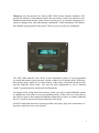
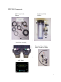
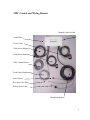
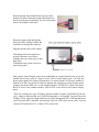
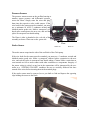
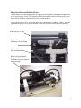
MPC-3000 INSTALLATION MANUAL Spectra Watermakers, Inc. 20 Mariposa Road, San Rafael, CA 94901 Phone 415-526-2780 Fax 415-526-2787 E-mail: [email protected] www.spectrawatermakers.com Rev 12-3-03 1 Thank you for your purchase of a Spectra MPC-3000 Control. Properly installed it will provide the ultimate in watermaking control and convenience. Please pay attention to the installation instructions and the system layout. Like any piece of electronic equipment it is subject to damage from water and improper installation. Careful installation will enhance the reliability and enjoyment of the system. This kit is pre-wired for easy installation. The MPC-3000 controller is the “brain” of your watermaker system; it is pre-programmed to control and monitor system pressure, vacuum, salinity level of product water, gallon-perhour product output, tank level, as well as control, of the pumps, the product diversion valve and the freshwater flush system. The unit has been programmed to run in different “modes” (production mode, timed mode and flush mode. No changes to the wiring should be necessary, unless you wish to install additional options or lengthen any of the cables to suit your installation needs. If this is the case, please refer to the respective page in this manual for additional information on where to connect additional devices, as well as current and voltage limitations of the board. ALWAYS mount this unit away from any possible water spray, drips, hose connections, etc. Keep the control box cover on at all times. 2 Please Note, The MPC control must have DC power continuously to achieve the full benefits of the fresh water flush system. The domestic fresh water pressure must be on and the fresh water tank level maintained. Calculate 3 gallons (12L) per flush. The MPC 3000 control must be de-powered (DC power off) after the system is put in storage “pickled” where a storage chemical or antifreeze is run through the system. First, Unpack the system and inspect it to make sure that it has not been damaged in shipment. Refer to the shipping list to make sure you have received all of the components listed. Do not discard any packaging until you have found and identified all of the parts. The small installation parts are listed on the cellophane bags’ pick list. We will not be held responsible for shortages and or freight damage that are not reported within thirty days of the ship date. MPC-3000 Shipping List Control module with prewired harness MPC Display Panel Double Filter Housing Automatic Fresh Water Module Diversion Valve Assembly 3/8 Parker Tube 3/8 Tube to 3/8 NPT adapter fitting 3/8 Tube to 1/4 NPT adapter fitting MPC-3000 Manual Next, study the system layout diagram, component photos and descriptions before beginning your installation. This will assist you in understanding the function of each component. 3 MPC-3000 Components MPC Control with Harness Fresh Water Flush Module Duel Filter Assembly Diversion Valve, Salinity Probe Assembly w/fittings MPC Panel 4 Installation First , locate and identify the components that are to be integrated into your system. Review the MPC control and harness assembly to identify each of the leads and their function. Make sure that the harness will reach each component of the Spectra watermaker system before it is installed. It may be easier to relocate a component rather than extending the harness. Locate the MPC control central to the system components to keep the wire runs short and direct. The control harness assembly consists of the following, Power feed in 4’ (1.2M) Pump feed out 4” (1.2M) Pressure switch leads 6” (1.8M) Fresh water flush feed 15” (4.5M) MPC display cable 50’ (15.2M) Stroke sensor, Salinity probe and Diversion valve feed 15’ (4.5M) Mount the MPC control vertically on a bulkhead with the wiring access holes pointed down. Make sure that the control is located in an area that will stay dry and is not subjected to spray or drips. Do not connect any power to the control until you have finished all connections and are ready to test the system. The control is pre-wired and requires only a few connections to be made. Pay particular attention to the main power wiring or system performance will be compromised. Main Power feed should be connected to an uninterruptible power source and should be circuit protected with a fuse or circuit breaker. Mount the main power terminal block in a dry location between the control and the power source to keep the wire run short as possible. Install terminal block cover after making your connections. Wire lengths are for a pair of wires from the source to the terminal block location. Ventura or 200-C systems Fuse or circuit Breaker 20A Use # 10 Gauge wire (6MM) to 15 Feet (4.5M) Use #8 Gauge wire (10MM) to 25 Feet (7.6M) Use #6 Gauge wire (16MM) to 35 Feet (10.6M) 380-C Systems Fuse or circuit breaker 30A Use # 10 Gauge wire (6MM) to 10 Feet (3M) Use #8 Gauge wire (10MM) to 15 Feet (4.5M) Use #6 Gauge wire (16MM) to 20 Feet (6.1M) Use #4 Gauge wire (25MM) to 35 Feet (10.6M) 5 MPC Control and Wiring Harness Manual Control Switch Control Box Power Cable Filter Sensor Harness Pump Power harness MPC Control Harness Fresh Water Flush harness Stroke Sensor Diversion Valve Wire Salinity Probe Cable Clark Pump Harness 6 Route the pump feed terminal block near your feed pump(s) location. Mount the terminal block and connect your feed pump to the block. For two feed pumps remove the jumper on the block. Route the control cable through the boat to the MPC display location. Be careful not to damage the connector. Plug this into the back of the control. The displays must be mounted in a protected location, out of direct sunlight, and away from spray or dripping water. Commands to the system can be entered at any panel. Each remote control display panel can accommodate an external alarm buzzer to provide audible alerts in the event of a fault or at the end of certain timed cycles. Use only the buzzer units supplied by Spectra Watermakers, as current on the LCD buzzer terminal is limited to 20 MA, any excessive load may damage the controller or remote display panel. Connect the buzzer RED wire to the terminal marked +POSITIVE, connect the buzzer BLACK wire to the terminal marked –NEGATIVE on the back of the remote display panel. There are currently two types of display options available: Liquid Crystal Diode (LCD) display, which is dark lettering on a backlit background, or an optional Vacuum Florescent Display (VFD), which are bright characters on a dark background. The VFD demands more power from the MPC controller, and currently, only one VFD can be run at a time. You can run one VFD and two LCD’s, or three LCD’s at any time. 7 Pressure Sensors The pressure sensors mount on the prefilter housing to monitor system pressure and differential pressure across the filters. Simply route the wires and plug them into the respective color coded sensors. If the wire leads for the sensors must be extended, you must use a minimum 18 AWG 3 conductor twisted and shielded marine grade wire. Make a waterproof, soldered splice connection to the new wire, and seal the splice in waterproof heat shrink tubing. The Water is inlet is plumbed to the red side of the assembly as shown. Water out on the green side. Stroke Sensor Flow Water out Water in The stroke sensor snaps into the side of the end block of the Clark pump. If the wire leads for the sensor must be extended, you must use a 3 conductor, twisted and shielded marine grade wire. Make a waterproof, soldered splice connection to the new wire, and seal the splice in waterproof heat shrink tubing. Caution! Make certain that no extra strands are free to make contact with other conductors or components. Integrity of the sensor wiring is critical, as any loss in the connections will be interpreted by the controller as a “SYSTEM STALLED” condition. Be sure to carefully solder-tin the bare strands of the wires before inserting them in the terminal plugs. If the stroke sensor must be removed, use a pen knife to find and depress the opposing clips holding the sensor to the block. 8 Diversion Valve and Salinity Probe The diversion valve and salinity probe is supplied as an assembly. Mount this assembly near or on your pressure vessel. The assembly should be oriented with the salinity probe down. Make sure to install the watertight boot over the salinity probe. Locate the diversion valve wires and splice the remaining two conductor cables with the supplied butt splices. These are heat shrink connectors so you can seal them after splicing. Product Water to Tank Product Dump Line to the Brine Discharge on Clark Pump Salinity Probe Note Orientation Remove Plug and Install Adapter for Brine Dump See Parker assembly instructions next page. 9 Parker Tube Fitting Assembly Procedure Body Step 1: O-ring Spacer Single grab ring for 1/4" & 3/8" tube Use 2 grab rings for 1/2" tube Nut Tubing Dissemble fitting components 1/2" max Step 2: Install the Nut first then use the bevelled side of the Spacer to push the Grab Ring onto the tube no more than 1/2". Slip the O-ring over the tube to hold the Spacer in place. If the Grab Ring is pushed too far, trim back the tube so about 1/4" of tube extends past the O-ring. Step 3: Gently fit the tube into the body and loosely thread on the nut. Be careful not to cross-thread the nut 1/2" tube should not bottom out in the fitting to allow full compression of the O-ring Step 4: Hand tighten the nut. DO NOT OVER TIGHTEN! DO NOT USE A WRENCH! The tube should not come out if pulled by hand. If it does, tighten the grab ring tabs. 1/4", 3/8", 1/2" Parker Tube Fitting Assembly 10 Fresh Water Flush Module Ventura and 380-C systems Route the single two conductor harnesses to the fresh water flush module and splice the wires to the solenoid wires. Heat the splice for sealing. Plumb the fresh water flush module between the Sea Water strainer and the feed pump. Connect the Carbon filter to the pressre side of the ships domestic water system. The system must be able to supply 2 Gallons (8L) per minute. The ships water system must stay active during the auto store mode for automatic flushing to occur. Connection of Optional Accessories 11 Connection of Optional Accessories Use of any external devices not approved by the factory may cause permanent damage to the controller and is not covered by the Spectra warranty. Accessory outputs are limited to 2 amps maximum load! Do not connect motors, pumps, etc to accessory outputs. Optional Z-Guard System: Detailed instructions are included with the Z-Guard kit. Connect to the “Aux1” and “GND” terminals of the MPC board. Ultraviolet Sterilizer: Detailed instructions are included with the sterilizer kit. The UV sterilizer lamp module and ballast unit should mount vertically, with the product water inlet at the bottom, outlet at the top. The ballast wires plug into the end of the bulb in the lamp module. The ballast RED wire connects to “STER” terminal on the MPC board, and the ballast BLACK wire connects to the “GND” terminal. If the wires must be extended, use minimum 16AWG wire. External Buzzer(s): In addition to the external buzzer(s) installed at each remote control display panel, a buzzer unit may be installed at the control box. The buzzer RED wire connects to the “BUZZ” terminal on the MPC board, and the buzzer BLACK wire connects to “GND.” Tank Switch Operation: The MPC controller can be set up to use your tank switches in two ways. For normal operation (using either Manual Run mode or Auto Run mode) simply connect the switches to the Tank1 and Tank2 connections on the MPC board. If only one switch is to be used, connect a jumper across the unused tank connection. Note that the switch must be installed in a position that will cause it to close (short) when the tank is full. In Manual or Auto Run mode, the system will stop producing water when both tank switches are closed, perform a fresh water flush, and shut down. Jumpered for only 1 switch To Tank 1 Switch Tank 1 Connection Tank 2 Connection 12 Automatic operation : Automatic operation for land based systems may be achieved by installing a low point tank switch and a high (full) tank switch. Tank 2 switch is be the low point or system on and tank switch 1 will be the high point system off switch. The system should then start when the tank low switch opens and shuts off when the tank one or high point switch closes. The unit will perform a FW flush after the run cycle and default into the five day flush cycle. How it Works: Press and hold the “Auto Run” button for 5 seconds– the display will read “AUTO FILL MODE”. The system will begin operation and produce water, filling the tank. Eventually the water level will rise until it reaches the “maximum” switch– at this time, the display will read “TANK/S FULL”; the system will at this point stop producing water, perform a fresh water flush, and then go into a 5-day flush cycle storage mode. The display will cycle “TANK/S FULL” and “FLUSH TIMER INTERVAL”, indicating the time remaining until the next flush occurs. As you use the water in your tank, the water level will drop until it reaches the “minimum” switch– at this time the system will ‘wake up’ out of storage mode, sensing that the minimum tank level has been reached, and will begin to produce water again until the water reaches maximum. 13 New System Start-Up and Testing Avoid running the system if the vessel is in contaminated water, such as in a harbor or canal. The system should be fully run tested before leaving port. It is preferable to sacrifice a filter by running the system in turbid water rather than waiting to get offshore to discover a problem or deficiency in the installation. If the location or weather prevents proper testing refer to the section “Dry Testing.” Warning! Damage may occur if the purge sequence is bypassed and the membrane is pressurized with storage chemical in it. 1. First Check That: • Thru-hull valve is open • Power is on. If you have an AC system both the AC power and the DC control voltage to the unit needs to be on. • Domestic fresh water system must be on. 2. Open pressure relief valve 1/2 turn ! 3. Power up the system • Alarm will sound - • Push the Alarm /Display button to silence alarm 14 4. Press Auto Run Button The system will go into a start mode and the feed pump will start shortly after. The system should prime within 60-90 seconds. Check the strainer and the brine discharge for water flow. There should be no bubbles anywhere in the intake hoses and the feed pump should sound smooth after priming. If the feed pump continues to sound rough, find the reason before continuing! Inspect the system for leaks. Note: If you must stop the purge sequence for any reason, the control will default back to the beginning of the purging mode to protect your system. If you wish you can bypass the purge sequence and initiate a normal start. Pressing both “Auto Run” and “Stop” simultaneously anytime during the purge sequence will bypass the purge sequence and enable a normal start. 5. After the purge sequence. The control will alarm with the message “Close pressure relief valve” - Close the valve and proceed by pressing “ Auto Run.” 6. The system is now running under pressure and making water. The display will read “purging product water.” This mode dumps the product water overboard for ten minutes in case there is any residual chemicals in the membrane. Carefully inspect for leaks over the entire system! Shut down the system and repair any leaks you find. 7. The system is now in the operational mode. You may start and run you system as you desire. You will not have to go through the purging mode unless you “de-power” the system. If you do, you can bypass the purging mode by pushing “Stop” and “Auto run” buttons at the same time. It is best to use the auto-run button which defaults to the automatic fresh water rinse. If you shut down the system from the stop button then use the auto store button to effect a fresh water flush cycle. 8. Check that the system is operating within its normal parameters. Compare with the chart on the next page 15 Product Flow Ventura 6-7 GPH (24-27L) 380-C 14-16 GPH (50-55L) Salinity This may not show any lit bars on a new system. One bar represents 100 PPM. System rejects water higher than 750 PPM. Feedwater Pressure Ventura 65-85 PSI (4.5-6.5 Bar) 380-C 75-100 PSI (5-7 Bar) Filter Condition Clean filters on first alarm as soon as convenient. 16 Normal Start Up Using the Auto Run Button • Press Auto Run button once and the system will prime and run for 1 hour. The display reads “AUTO RUN MODE” then “STARTING” with a 30 second priming countdown timer. After the prime, the display reads “AUTO RUN MODE” with a countdown timer. An hour of run time is added, up to 12 hours, with each successive momentary press of the Auto Run button. An hour can be added at any time. The display shows the default readout unless there is an alarm condition. Successive presses of the Alarm/Display button will scroll through the displays starting with “GPH PRODUCT.” Upon auto shut down by the timer or by the optional tank full float switches, the system will automatically fresh water flush and re-flush every 5 days. • Pressing the Stop button stops the sequence at any time with no flushes. Normal Operation • For optimum performance, Auto run the system as long as possible at one time. Never let the system sit with salt water in it. Never allow continuous air leaks in the intake. Normal Shut Down • If the system was started using the Auto Run button, the system will shut off on its own when the selected run time is over and will auto flush every 5 days. • Pressing the Stop button at any time will shut off the system with no auto flush function. • The optional tank float switches will shut off the system from any mode. If the system was started by the Auto Run button the system will flush and then re-flush every 5 days. If the system was started by the Start/Stop button it will do a 1 time flush. The display will read “TANK/S FULL.” Once one of the tank float switches opens, the alarm and “TANK/S FULL” display will cease on its own. Note that if “TANK/S FULL” is displayed, the system cannot be restarted. 17 Automatic Fresh Water Flush Cycle Warning! Proper understanding of the Spectra flush system and the vessel’s fresh water system configuration is mandatory for extended automatic flush cycles. The flush cycle must not be allowed to drain all the fresh water from the vessel or damage to the vessel’s systems may occur. • Make sure there is enough water in the fresh water supply system to supply the watermaker for more than the expected time of operation in the “re-flush every 5 days” mode. The 400 requires 4 gallons (16 liters) and the 700/1000 units require 6 gallons (24 liters) every 5 days. • Make sure that the pressure water supply is on and will stay on during the flush mode (If this is not possible contact your certified dealer.). • Make sure that the pressure relief valve is closed. It should be closed if the system was just used to make water. The auto flush may not operate if the valve is open. • The power for the system must remain on during the auto flush mode. Turning off the power will disable the auto flush function and damage may occur. • Pressing the Auto Store button will engage a flush and then the 5 day flush cycle. The flush pump starts and the flush water solenoid opens for 5-7 minutes and then shuts down the display reads “FRESH WATER FLUSH” with a countdown timer and then will read “FLUSH TIMER INTERVAL” and the countdown timer will reflect the number of hours until the next flush. • Pressing and holding the Auto Store button for 3 seconds will engage a 1 time flush. The system flushes as described above but will not re-flush every 5 days. Display will read “FRESH WATER FLUSH” with a countdown timer, then the default display when finished. • Pressing the Stop button will cancel the auto flush mode. 18 Emergency Operation • In the event of an MPC control failure, the system may be operated manually using the manual feed switch on the MPC control box. • For manual start up, switch on the feed pump using the feed pump switch. Shut the unit down if the Clark pump does not cycle. Shut down if air is continuously present in the intake line or if the feed pump is excessively noisy. The automatic safety controls are disabled in manual mode. • Always discard the product water for the first few minutes of operation. The initial product water from the system may not be potable. Taste the product water before sending to a tank. • In manual operation, the salinity control is inoperative. Product water is available either directly from the membrane product water out or at the diversion valve brine outlet. You will have to bypass the diversion valve with the parker tubing. Disconnect product fitting. Remove check valve and reconnect the Brine tube to the check valve as shown. Connect Product tube to diversion valve. Activate manual switch. 19 Salinity Probe Calibration: Salinity is a measurement of TDS, total dissolved solids in liquid: these solids will conduct electricity to varying degrees. A special probe is used, with two electrical contacts in it, to determine the resistance to the flow of electricity in the liquid. In the Spectra Watermakers systems, the salinity probe is located just before the diversion valve, at the output of the RO membrane. This way we can look at the salinity level of the product water before deciding to either reject the water or accept it and divert it into the holding tank. The salinity level in parts-per-million can be seen either through the salinity meter in the software, or a jumper can be added to the MPC board in the ‘calibrate’ position, where it can then be seen on the LCD display (rather than a bar graph). After adding the jumper, it may be necessary to cycle through the different LCD displays until the display reads ‘salinity.’ Procedure: 1. Locate the Calibrate jumper location on the MPC-3000 Board. Jump the terminals 2. Start the system and after the salinity stabilizes, test the product water with a calibrated hand held tester. 3. Locate the MPC calibration trimmer potentiometer on the board below the salinity probe jack. Adjust until the display PPM matches the PPM reading from the hand held salinity monitor. Turning the trim pot clockwise will lower the salinity reading, and counterclockwise will raise it. 4. Shut the system down and disconnect the jumper on the MPC board. If a hand held meter is not available you can remove the probe and dip it into a known calibrated solution. This can be obtained from Spectra. 20 Spectra MPC-3000 Operation Guide This document is a outline of MPC-3000 operations. It details what is seen on the LCD display during the various modes of operation. 21 Power On Power On OPEN PRESSURE RELIEF VALVE NOW Initial Startup Purge Mode Auto Run STARTING or 2:00 Pump2, Pvlv, Aux1, Aux2 When 30 seconds remaining, Pump2 Off, Pump1 On Start Stop Purging All Off, Aux1 On PURGING STORAGE SOLUTION 18:30 Pump1, Pump2, Aux1, Aux2 Countdown to 0:00 Done CLOSE PRESSURE RELIEF VALVE NOW All Off, Aux1 On Close pressure relief valve and press Start/Stop Start Stop RUN HIGH MODE Pump2, Pvlv, Aux1, Aux2, Ster Displayed for 10 secs Priming STARTING 2:00 PURGING PRODUCT 10:00 Making Water Bypass Purge Mode Auto Run and GPH PRODUCT 4 ٱٱٱٱٱٱٱٱٱٱٱ22 22 When 30 seconds remaining, Pump2 Off, Pump1 On Pump1, Pump2, Aux1, Aux2, Ster Pump1, Pump2, Dvlv*, Aux1, Aux2, Ster PURGE MODE BYPASSED Start Stop Simultaneously 22 Manual Run Mode Start Stop RUN HIGH MODE Pump2, Pvlv, Aux1, Aux2, Ster Displayed for 10 secs Priming STARTING 2:00 When 30 seconds remaining, Pump2 Off, Pump1 On Making Water GPH PRODUCT 4 ٱٱٱٱٱٱٱٱٱٱٱ22 Pump1, Pump2, Dvlv*, Aux1, Aux2, Ster *Note on Diversion Valve Operation: During a water making mode, a 60 second salinity check is performed; If salinity is within tolerance (<700ppm) for a continuous 60 seconds, the Diversion valve will open, and the “good” LED will be lit. If salinity is out of tolerance, the Diversion valve will close, and the “reject” LED will be lit. Salinity must drop below tolerance and remain within tolerance for a continuous 60 seconds before Diversion valve will open. Press Low Mode Start Stop RUN HIGH MODE Then press again Start Stop RUN LOW MODE Pump2, Pvlv, Aux1, Aux2, Ster And hold for 5 seconds STARTING 1:30 GPH PRODUCT 4 ٱٱٱٱٱٱٱٱٱٱٱ22 When 30 seconds remaining, Pump2 Off, Pump1 On Pump1, Dvlv*, Aux1, Aux2, Ster 23 Auto Run Mode Auto Run RUN AUTO MODE 01:00 HOURS Pump2, Pvlv, Aux1, Aux2, Ster Note: pressing Auto Run again will add time in 1 hour increments Priming Making Water STARTING 2:00 RUN AUTO MODE 0:59 HOURS When 30 seconds remaining, Pump2 Off, Pump1 On Pump1, Pump2, Dvlv*, Aux1, Aux2, Ster Countdown to 0 Flush FRESH WATER FLUSH 5:00 Pump2 Cycles On/Off* Fvlv, Aux1 Countdown to 0 Storage FLUSH TIMER INTERVAL 119:59 Aux1 Countdown to 0 Perform Flush Cycle Repeats Note: Pump2 Flush On/Off times (seconds), as well as Storage Time (hours), are programmable via internal software Storage Mode Auto Store Flush Storage STARTING 5:30 FRESH WATER FLUSH 5:00 FLUSH TIMER INTERVAL 119:59 Pump2, Fvlv, Pvlv, Aux1 Pump2 Cycles On/Off* Fvlv, Aux1 Aux1 Countdown to 0, repeat Flush. Cycle repeats. 24 Press and hold Auto Fill Mode AUTO FILL MODE Auto Run Pump2, Pvlv, Aux1, Aux2, Ster For 5 seconds STARTING 1:30 AUTO FILL MODE When 30 seconds remaining, Pump2 Off, Pump1 On Pump1, Pump2, Dvlv*, Aux1, Aux2, Ster Will produce water until Tank1 switch closes Auto Fill Mode If Tank1 (max) Tank/s Full Switch closes.. TANK/S FULL Pump2, Fvlv, Pvlv, Aux1 STARTING 5:30 TANK/S FULL FRESH WATER FLUSH 5:00 Pump2 Cycles On/Off* Fvlv, Aux1 Display will toggle “Tank/s Full” to “Fresh Water Flush” every 5 seconds Countdown to 0 TANK/S FULL FLUSH TIMER INTERVAL 119:59 Aux1 Display will toggle “Tank/s Full” to “Flush Timer Interval” every 5 seconds Countdown to 0 If timer reaches 0, another fresh water flush will be performed If Tank2 (min) switch opens, Timer will interrupt, and unit will go back into Auto Fill Mode (Production Mode) 25 Run-time Readouts Alarm Disp Pressing Alarm/Disp at any time during run cycle will cycle through the following readouts: GPH PRODUCT 4 ٱٱٱٱٱٱٱٱٱٱٱ22 Push and hold Metric Alarm Disp Converts to Metric LPH PRODUCT 15 ٱٱٱٱٱٱٱٱٱٱ68 SALINITY LOW ٱٱٱٱٱٱٱHIGH FEED WATER PSI 50 ٱٱٱٱٱٱٱٱٱٱ150 Metric FEED WATER BAR 3 ٱٱٱٱٱٱٱٱٱٱ9 PREFILTER GOOD ٱٱٱٱٱREPLACE HOURS TOTAL 000000 26 If Inlet Pressure > Max Pressure (150psi for Newport Systems) HIGH PRESSURE Shutdown, Audible Alarm Alarm LED lit If Stroke not sensed for 30 seconds: RE-STARTING 2:00 Pump1 Off, Pump2 On Countdown to 0, retry previous mode If still no stroke RE-STARTING 2:00 Pump1 Off, Pump2 On Countdown to 0, retry previous mode If still no stroke SYSTEM STALLED Shutdown, Audible Alarm Alarm LED lit If no Inlet; 10” of vacuum sensed at vacuum switch: Error Occurred CK SEA STRAINER Begin FWF Mode Fresh Water Flush FRESH WATER FLUSH 5:00 Countdown to 0 Shutdown CK SEA STRAINER Audible Alarm, Alarm LED lit If problem corrects itself, Audible alarm off FWF Mode: Pump2 cycles On/Off, Fvlv, Aux1 Shutdown, Audible Alarm Alarm LED lit 27 If DC Input voltage too low: VOLTAGE TOO LOW Begin FWF Mode To Shutdown If DC input voltage too high: VOLTAGE TOO HIGH If salinity probe bad or disconnected: SALINITY PROBE FAILED CHECK FUSE X If blown fuse Begin FWF Mode To Shutdown Shutdown Shutdown (Where ‘x’ represents number of blown fuse (1-5)) If Tank1 or Tank2 switch closed for 2 minutes: If Tank1 AND Tank2 switch closed for 2 minutes: No display, software registers that Tank1 or Tank2 is full. TANK/S FULL Depending on operating mode, system may at this point begin a fresh water flush, begin storage mode, or shut down. Refer to Operating Modes. 28 If salinity above tolerance: Reject lamp lit, 20 minute internal counter begins Dvlv Off If salinity above tolerance for 20 minutes:: SALINITY HIGH FLUSH 5:00 Begin FWF Mode Audible Alarm Alarm LED lit Shutdown SALINITY HIGH Aux1 29