1
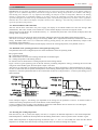
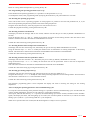
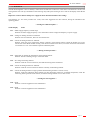
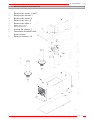
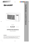
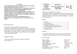
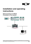
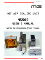
Air Sealer MS500 MG HOT AIR SEALING UNIT MS500 USER'S MANUAL WITH THERMOREGULATOR TR500 page 1 Air Sealer MS500 TABLE OF CONTENTS -1- Introduction ........................................................................................... page 3 -2- Technical specifications ......................................................................... page 3 -3- Description of TR500 control unit and of TR501 power unit ............... page 3 -4- Installation procedure...................................................................…….. page 4 -5- Operation…….........................................................................…........... page 5 -5.1- Initial installation and Calibration -5.2- Definition of operating parameters and typical operating cycles -5.3- Inserting working temperature -5.4- Programming operating parameters td, to, tp -5.5- Inserting operating program Pr -5.6- Inserting activation retard time td -5.7- Inserting duration time of temperature maintenance to -5.8- Inserting activation time tr for optoisolated outlet -5.9- Inserting pre-heating temperature tp -5.10- Verifying the operating parameters with a manual heating cycle -6- Warnings ................................................................................................ page 7 -7- Heating module maintenance ................................................................. page 8 CAUTION: When using the instrument, take care to follow the instructions given in the Manual IT IS OBLIGATORY TO ALWAYS MAINTAIN ACTIVE AIR THOUGH THE NOZZLES WHEN THE HEATING ELEMENTS ARE ACTIVE: ACTIVATE HEATING ELEMENTS WITHOUT AIR COULD SERIOUSLY DAMAGE THE UNIT. Before installing and using the instrument, read the following advice carefully: -*- Avoid installing the equipment close to high power units, relays, motors etc. -*- The equipment is NOT supplied with an ON/OFF switch, therefore it is switched on as soon as the power supply is connected. The power supply must have suitable protection against possible short circuits and faults in the equipment. Make the connections using cable types with sections that are appropriate for the voltage and current limits specified in the Manual. -*- Check that the plant has a good earth connection. -*- Before use, check and verify the settings for the operating parameters, so as to avoid possible damage to persons or objects. -*- The power supply voltage is shown on the label of the TR501 module. -*- Use the cable supplied for the connection between the two devices: pay careful attention to the colours of the wires when making connections to the terminal board of the TR501 module. -*- Do not use the equipment in environments with hazardous atmosphere (inflammable or explosive). page 2 Air Sealer MS500 - 1 - INTRODUCTION The MS500 are offered as a valid instrument for hot air sealing. Without the aid of external sensors the TR are able to regulate and maintain the pre-set temperature, even in conditions of high heat loss, thus achieving considerable advantages over other traditionally used methods. Using the TR500 module, which is supplied with a display and keypad, it is possible to insert all the operating parameters, while the TR501 module, to which it is connected, controls the heating parts at all times. Extremely easy to use, high functionality and minimal dimensions make this system the strong point for controlling processes of sealing by air heating, hot cutting, etc. . - 2 – TECHNICAL SPECIFICATIONS Power supply 230 V AC. Frequency 50 / 60 Hz. Power consumed at rest 4 W. Maximum power output 900W. (duty cycle at 100%). Range of temperature regulation 30°C ÷ 300°C. Ambient working temperature from 0 °C to 50 °C. Maximum air pressure 3bar, 43psi - 3 - DESCRIPTION OF TR500 CONTROL UNIT E TR501 POWER UNIT VIEW OF PANEL TR500 REAR VIEW AND DRILLING POINTS VIEW FROM ABOVE POWER UNIT TR501 Control unit TR500 with flush-mounted panel to DIN 43700 standard, material self-extinguishing NORYL UL 94 V-O, size 48 x 96 x 118 mm.. Power unit TR501 on container attachable to Din EN50022 guide, to DIN 43880 standard, material self-extinguishing NORYL UL 94 V-O, size 106 x 90 x 69 mm. (6 modules). Connection of control unit to power unit with shielded cable, 9 way x 0.22, with 15 pole female socket connector. page 3 Air Sealer MS500 - 4 - INSTALLATION PROCEDURE Connect 24Vcc to the CKF04 connector as in picture. Insert and fasten, using the two screws, the 15-way female connector to the control unit TR500. Connect the other end of the cable to the terminal board of the power unit TR501 as shown in the diagram below: To the terminal board of the connector TR501 15 pole female socket N.B.: Take care not to invert the connections !! In the TR501unit, to the input terminals 1 and 2, must be applied the signal to activate the sealing cycle (START). This signal can have a voltage between 12V AC and 24V AC or from 12V DC to 30V DC attaching the positive to terminal 2 and the negative to terminal 1, with a current consumption of approx. 10 mA. At terminals 3 e 4, there is an optoisolated outlet that indicates the end of the operating cycle (IN WORK): this photo coupler is closed throughout the whole sealing cycle, to return to the deactivated position at the end of the cycle, and can be configured externally as either NPN or PNP, with a maximum current that must not exceed 50 mA and 24 V DC. When making the connection pay attention to the polarity of the receiver (terminal 3) and the transmitter (terminal 4). At the ends of the element connect two twist-wires, section 0.22÷0.50 mm².: these two wires must be connected to terminals 5 and 6 respectively. For any fault indications (see chapter 8), use the contacts N-C or N-O, connected respectively to terminals 10-11 and 10-12 (maximum current 5 amp. at 24 V AC). To terminal 13 connect a protective fuse of 6.3 amp. Connect the fuse output and terminal 14 to the primary of the power transformer using cables with a minimum section of 1.5 mm². At the secondary side of tranformer use cables with a section of 2.5 mm² to connect the output of the transformer to the heating element. For the other output from the transformer: pass it 2 times through the central hole in the TR501 unit to do a coil and then connect it to the other end of the heating element. Connect the earth to terminal 15. Connect the main power supply to terminals 16 and 17. Select in the rear selector of the TR500 unit the Toss position page 4 Air Sealer MS500 - 5 - OPERATION IMPORTANT: the operation of automatic calibration must be carried out with the temperature of the heating element at approx. 18÷25 °C (ambient temperature) and with air trough the nozzle. During this procedure the resistance will undergo some heating tests, therefore it is very important that nothing can interfere to alter its temperature. Whenever the heating element is replaced due to accidental breakage or for other reasons, the calibration procedure described below must be repeated. Throughout the initial start-up and calibration phase, the TR thermoregulator may encounter some irregularities and show their error codes on the display. Carefully read the section “Warnings” and, when the problem has been resolved, repeat the procedure from point 6.1 . -5.1- Initial installation and Calibration After the TR has been connected to the power supply, the display of the TR500 module will show the message “ Ini” (Initialisation): after a few seconds, some random error codes could be displayed. Activate air trough the nozzle. At this point press both the key “F” and the direction key “” simultaneously until, after a few seconds, the display shows the message “Tar” (Calibration). Release the two keys: this begins the phase of automatic calibration between the TR module and the heating element. After about 2-3 minutes, the display will give the message “PAE” (Error Amplification Parameter) and then the value of the setting: the default value is set at 15. Confirm this value by pressing the key “F” (this will be followed by analysis of the functionality of this parameter). The calibration phase is then terminated and the display will show the working temperature, set by default at 250 °C. -5.2- Definition of the operating parameters and typical operating cycles The parameters that can be configured by the user allow modification of the TR operating mode. Pr= program number tp = pre-heating temperature. td = retard time for activation of the heating element after the START signal. tl = working temperature of the heating element. to = duration time of maintenance at working temperature of the heating element. Figure 1 shows a typical operating cycle for the TR: from the pre-heating temperature setting tp, following the arrival of the rising front of the START signal, the outlet photo coupler is activated. After the pre-set retard time td, the heating element will be taken to working temperature tl and maintained there for the preset time to. When tihis time has passed, the temperature of the eheating element again falls to the pre-set value for pre-heating temperature, while the optoisolated outlet is still connected for the time set in the parameter tr: in this way the heating cycle is then terminated. figure 1 figure 2 In the example in figure 1, the heating cycle depended on the settings for the parameters td and to. It could be useful to maintain the working temperature for the whole duration of the START signal. To have a welding cycle as in figure 2, the parameters retard time td and duration time to must be set at zero during the programming phase (td=0 hundredths and td=0 hundredths). -5.3- Inserting the working temperature Each time the key “F” is pressed, the display will show, in sequence, the detected temperature or the settled temperature. Settled temperature is defined as the temperature that the heating element has to reach in presence of the “START” signal. When settled temperature is displayed pressing the direction keys “” and “” will modify the value until the desired temperature is reached. If the direction keys are kept pressed down, the value will change more rapidly. page 5 Air Sealer MS500 Return to viewing detected temperature by pressing the key “F”. -5.4- Programming the operating parameters (td, to, tp) In the submenu of the operating parameters, it is possible to set the parameters td, to e tp. To modify these values, enter programming mode by keeping the function key “F” pressed down for 4 seconds. -5.5- Inserting the operating program Pr The Tr 500 is able to store 9 operating programs: for each program it is possible to store the time parameters td, to, tr, the value of the pre-heating temperature tp and the value of the sealing temperature. Using the arrow direction keys, select the program to be used, from Pr 0 to Pr 9. Confirm the program selected by pressing the function key “F”. -5.6- Inserting activation retard time td The display will show the message “td” for one second, and then will show the pre-set value (by default 0 hundredths of a second). Using the direction keys “” and “” modify the activation retard time for the heating element. This must take a value between a minimum of 0 and a maximum of 239 hundredths of a second. Confirm the value inserted by pressing the function key “F”. -5.7- Inserting duration time of temperature maintenance to The display will now show the message “to”, followed by the pre-set value (by default 0 hundredths of a second). Using the direction keys “” and “” modify the duration time of maintenance at working temperature of the heating element. This must take a value between a minimum of 0 hundredths and a maximum of 239 hundredths. Confirm the value inserted by pressing the function key “F”. -5.8- Inserting activation time for optoisolator outlet tr The display will now show the letters “tr”, followed by the pre-set value (by default, 0 hundredths of a second). Using the direction keys “” e “” modify the activation time for the optoisolator outlet at the end of temperature maintenance time to. This value must be between a minimum of 0 hundredths and a maximum of 239 hundredths. Confirm the value of the setting by pressing the function key “F”. -5.9- Inserting pre-heating temperature tp The display will now show the message “tp”, followed by the pre-set value (by default 30 °C.). Using the direction keys “” e “” modify the value of the pre-heating temperature for the heating element. This must take a value between a minimum of 15 °C. and a maximum of 499°C. Confirm the value inserted by pressing the function key “F”. The parameter programming phase is thus completed: the display will return to showing the setting for the working temperature. -5.10- Verifying the operating parameters with a manual heating cycle. To verify the correct functioning of the parameter settings, it is possible to activate a manual heating cycle: from the mode for viewing working temperature, press the key “F” and pass to viewing bar temperature. At this point, when the direction key “” is pressed, the manual heating cycle will be started (a simulation of the “START” signal). The display will show, with the lighting up of 3 LED’s, the activation phases for the times td, to and for the whole heating cycle tc (LED on = cycle running/ LED off = cycle completed). When correct operation has been verified, the TR thermoregulator is ready to be set in operation. page 6 Air Sealer MS500 - 6 - WARNINGS The TR thermoregulator is able to identify a whole series of faults that could occur in the electric and electronic circuits, and will signal the error both by commutation of the warning relay and by the showing an error code on the display of the TR500 unit. Important : Ensure that the main power supply has been disconnected before intervening ! The following is a list of the possible error codes, with some suggestions for their solution, during the installation and operating phases. --- During the calibration phase --On the display Fault Er1 = Mains supply frequency outside range. Solution: the mains supply frequency is not 50/60 Hertz. Check voltage and frequency of power supply. Er2 = Voltage on heating element not sufficient. Solution: Check connections, there's an unconnected one. Er3 = Current in heating element not sufficient. Solution: check the circuit connections and the continuity of the heating element. Check the double turn on the current hole of the TR500 module. Finally, if all checks are found to be correct, invert the connection from terminal 5 to terminal 6 or vice versa and then repeat the calibration phase. --- During normal operation--Er4 = Impossible to regulate the temperature on the heating element. Solution: There's something wrong in connected cables. Er5 = No voltage on heating element. Solution: check the circuit connections, fuse and functioning of the transformer. Er6 = Current in heating element not sufficient. Solution: check the circuit connections and the continuity of the heating element. Er7 = Current in heating element too high (possible that the heating element is in short circuit). Solution: repeat the calibration phase making sure that the heating element is at ambient temperature; check the connecting cables (possible earth contacts) or that the heating element is not in short circuit. --- During the start-up phase --Er8 = Fault. Solution: return the equipment to the manufacturer. Er9 = Fault. Solution: return the equipment to the manufacturer. page 7 Air Sealer MS500 - 7 – HEATING MODULE MAINTENANCE – – – – – Remove the screws 1 and 2 Remove the nozzles 3 Remove the screws 4 Remove the cover 5 Remove the tubes 6 – – Remove the screws 7 Remove the cover 8 – – Loosen the spacers 9 Disconnect terminal block from resistors Remove resistor-s 10 – page 8 Air Sealer MS500 FAST INSTALLATION GUIDE WARNINGS For having always air to the needed temperature, during the pause with the spouts turned, maintain the air active through the nozzles and keep the resistances to sealing temperature (START signal always active). In warm atmospheres, it is obligatory to maintain MS500 module ventilated (must always inhale fresh air). IT IS OBLIGATORY TO ALWAYS MAINTAIN ACTIVE AIR THOUGH THE NOZZLES WHEN THE HEATING ELEMENTS ARE ACTIVE: ACTIVATE HEATING ELEMENTS WITHOUT AIR COULD SERIOUSLY DAMAGE THE UNIT. INSTALLATION PHASE Once executed all the electrical connections, connect the compressed air tube to the MS500 module: with a pressure regulator, connect in the connection number 1 the air that will go to the welding nozzles (this regulator should be regulated to 0.5 Atm during the setting phase, and to 3 Atm during the normal welding phase).In the connections number 2 and 3, connect the air in order to make the nozzles turn ( up to 3 atm maximum). SETTING PHASE MAKE SURE THAT MS500 MODULE IS TO AMBIENT TEMPERATURE AND THE PREHEATING TEMPERATURE IS SET TO 30°C. Activate nozzles air to 0.5 Atm pressure. Give voltage to the system and wait 5 seconds. At the same time press the push-button “F” and the arrow key “” until on the display will be visualized “Tar” (calibration). Release the two push-buttons: it begins therefore the automatic phase of calibration of TR module . After approximately 4-5 minutes, the dispaly will be able to visualize two messages: the written “PAE” (Parameter of Amplification Error) or an error message. In presence of the error message, the connection threads will have to be inverted from clip 5 to clip 6 and vice versa on the TR501. Then repeat the phase of calibration; while if the written one appears “PAE” will have to be set up the value to 15 (default). Confirm with the “F” key. Press two times the “F” key to exit the calibration phase. Now the MS500 module and TR control are ready to work. page 9