1
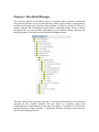
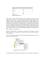
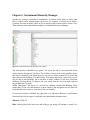
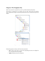
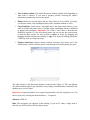
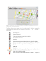
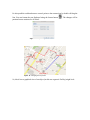
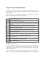
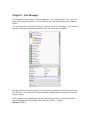
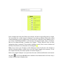
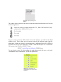
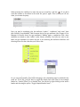
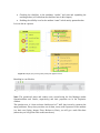
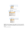
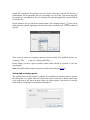
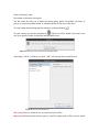
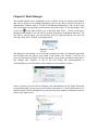
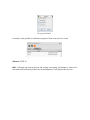
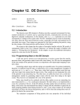
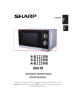
Kuwaiba Open Network Inventory
Version 0.5 [12.12.2013]
User Manual
Please visit http://www.kuwaiba.org for documentation, latest updates and upcoming events
Change History
Responsible
Charles Bedón
[email protected]
Charles Bedón
[email protected]
Charles Bedón
[email protected]
Charles Bedón
[email protected]
Charles Bedón
[email protected]
Charles Bedón
[email protected]
Charles Bedón
[email protected]
Charles Bedón
Description
Date
First issue shipped with version
0.1.1.
September 28
2010
Reviewed by
th
Update to cover the new features in November 26th
version 0.2
2010
Update to cover the bugfixes and December 26th
changes in version 0.2.1
2010
Changes in version 0.3 alpha
January 18th
2011
Changes in version 0.3 beta
February 3rd
2011
Changes in version 0.3 beta 2
March 13th
2011
Changes in version 0.3 stable (the
clear button in the graphical query May 16th 2011
editor)
Adapted to version 0.4
May 23rd 2012
Adrián Martínez
adrian.martinez@kuwaiba.
org
Adapted to version 0.5
Oct 23rd 2012
Charles Bedón
Charles Bedón
Added documentation
module
Jun 4th 2013
Adrián Martínez
[email protected]
Adrián Martínez
[email protected]
Charles Bedón
[email protected]
for
Pools
Added documentation for Data
model Manager module and some Jun 12th 2013
other minor changes
[email protected]
[email protected]
[email protected]
Adrián Martínez
[email protected]
License
This document is published under the terms of a license Creative
Commons by-nc-sa. You can find details about it at
http://creativecommons.org/licenses/by-nc-sa/2.0/
Kuwaiba Server and Client are licensed under EPL v1. You can
find the whole text of this license at
http://www.eclipse.org/legal/epl-v10.html
Disclaimer
•
Netbeans and Java are registered trademarks of Oracle and/or its affiliates. Other
names may be trademarks of their respective owners. The Kuwaiba project is not
endorsed in any way to any of them.
•
This document is provided “as is”, with no warranty at all. Install the software and
follow the instructions included at your own risk.
•
Kuwaiba uses third-party components licensed under compatible licenses (LGPL,
BSD-like). You can find a complete list at the project's web page.
Chapter 1. Network Inventory Management in a nutshell
When you have a lot of things is easy to lose some of them and it's even easier to end up
with a monumental mess if you're not organized enough. As a result, you will find yourself
buying something you already have but you haven't managed to find, or wasting precious
resources (money or space) storing stuff you barely know what is for.
The same happens to the IT and telecommunications infrastructure (actually in nearly every
business handling assets [1]). It tends to be complex and its components lose visibility as
the base of users/subscribers/customers increases. So it's common to see servers,
workstations, antennas and equipment of all species piled in some dark room. In the mean
time, sysadmin or technical guy's mind apart, it's not possible to find the updated
information about the operative elements configuration or even location, the rack space is
wasted and the patch panels are a land of no one, so how will anyone know which cable to
pull?.
They say you can't manage what you can't control, and you can't control what you don't
measure, and that's more or less the point of all this inventory thing. If you have under
control what you have and the way everything is related will be more likely to achieve the
goals of the Operations Department or the IT Staff, if they use this information to attend the
incidents effectively and plan the capacity the more accurately way possible, among other
things.
Having said this, three possible types of resources may be identified:
•
Physical: These are the equipment, pipes, cables, fiber optics, facilities, parts and in
general every physical asset from a port to a building.
•
Logical: These are all the resources related to non-tangible technology assets. In
this group fits timeslots, virtual circuits, VLANs, disk space, available bandwidths,
etc.
•
Administrative: These are all those related to administrative tasks, human
resources or services. Here you can find customers, services associated to those
customers, SLAs (and related parameters like availability or throughput), account
managers, technical staff assigned to those services, vendors, brands. In short, all
not-operational resources related to a given service management workflow.
As you may guess (or have experienced), to have all this information updated and complete
at a single point is a hard task. Mostly because IT and telecommunications are ever
changing environments and your network configuration layout can shift overnight.
Updating all the data manually is almost impossible, but fortunately, you can grab a good
part of it from the network elements if the have proper management interfaces.
From an ITIL perspective [2], within the Service Transition process there's a key concept
called “CMDB”. In short, is a place where you have Configuration Items (CIs, any IT asset
that can be configure or have configuration information) and their relationships. Yes, not
only the objects. Indeed, multiplexers, radios, routers are not islands. They're connected
physically or logically, and people may be related to them as well. A network inventory
system is a CMDB but may extend its functionality in order to provide workflow
management, network designing features, etc. But the core of it is a Configuration
Management Database.
But one thing is different from other scenarios is that technology assets may not be
physical. If you have a core using SDH you need to know what VCs are free, which ones
are protected and what kind of protections they have, but if you manage switches you may
want to now the bit rate configured for a given port or how the VLANs are set up. At
application level, you'd like to know what DNS are configured for a given Web Servers or
where are the Domain Servers...
Kuwaiba Open Network Inventory aims to be a solution for this scenario. It is
completely Object Oriented, so you can model your network according to your needs, no
matter if you're an ISP, a carrier or just a guy with a large IT infrastructure. Remember,
Kuwaiba is under active development and new models are added every release. Please
request the ones you consider as top priority in this thread [3].
Chapter 2. The login window
The default user/password is admin/kuwaiba. When you execute the binary at
$CLIENTPATH/bin/kuwaibainventory
(Unix-like
systems)
or
$CLIENTPATH/bin/kuwaibainventory.exe (Microsoft Windows® systems) you'll get a
window like this (remember, you need JRE1.6 or superior to run the client. Check here [4]
for details):
Figure 1: Login window with the Connection
Settings panel collapsed
Pressing “Cancel” will close the application, and pressing “OK” will attempt to log into the
system using the default connection values. This is, localhost as server, 8080 as server port
and “/kuwaiba/KuwaibaService” as WSDL location. If you deployed the server with the
default settings in the same box as the client, this should be enough.
Figure 2: Login window with the Connection
Settings panel expanded
You can expand the Connection Settings panel in case you want to change those values.
•
Server address: Name or IP address where the server is running
•
Server port: Port where the applications server is listening at.
•
WSDL Path: Path to be appended to the server address and port to form the valid
URL to access the WSDL expose the methods to be consumed. It's important to
point out that the Kuwaiba desktop client has a webservice client within, and that's
the mechanism used to interact with the server. If you're not sure about this value,
try typing in web browser an URL like this:
http://<server_address>:<server_port><wsdl_location>
An XML document must be displayed
If you were able to log in successfully, the first thing you will see is an empty window with
only a toolbar at the top.
Troubleshooting: You can get a “Not enough privileges” message in case the
user/password provided are invalid. If you get an “EJBException” that means an internal
server error occurred, so you probably need to take a look at the server log for details, but
most of the problems in this regard has to do with the database connection (the database
server is not running, can't be reached or the credentials used to access it are invalid).
Contact the application administrator if you get this error. A “HTTPServletException:
Connection refused” indicates that the server is not running at all (or couldn't be found),
check if the WSDL location is correct.
Figure 3: Main toolbar layout
Query Builder (Chapter 9)
Refreshes the local cache. Use it whenever you make a change to the class
metadata (i.e, when you change the icon or display name for a given class or
when you add a new list type element). Also hit this button if you add a new list
type item.
Refreshes the current focused component
Basic view (Chapter 6)
Topology Manager (Chapter 8)
User and Group Management (Chapter 12)
Data Model Manager (Chapter 2)
Containment Hierarchy Manager (Chapter 4)
List Manager (Chapter 9)
Navigation Tree (Chapter 5)
Pools Manager
Chapter 2. Data Model Manager
One of the key features of Kuwaiba is that it is completely object oriented. It means that
every business (Router, City, Port) and application (users, types) element is represented by
an object in the application. Likewise, every attribute is a Field in a Class [5]. The set of
classes, attributes and relationships between them is called data model. There's a default
data model, but you can customize it depending on your needs by adding, removing and
modifying classes. To do this, use the Data Model Manager module.
Figure 51: Data Model Manager main window
The main window shows the class hierarchy, at least from InventoryObject (its subclasses
represent all the possible elements that are treated as inventory assets) and
GenericObjectList (each subclass is a list type. See chapter 7 for details). To edit a class,
open the Properties window (Window → Properties), and after selecting a node in the tree,
you will see something like this:
Figure 48: Class properties
The property sheet is divided in two sections: General, which contains the properties of the
class itself, such as its name (can contain only letters and numbers with no special
characters or blank spaces), the way the class name will be displayed everywhere else
(useful for internationalization purposes), a description (useful to document the data model
as it grows), if the class is abstract (abstract classes can not be instantiated, they're used to
give consistency to the data model). Sometimes, the construction of an extension of the
default data model takes time, use “In design phase” to mark a class as part of an ongoing
work to extend the data model. Classes with this attribute set to true can't be instantiated.
All new classes have it set to true by default. Countable is not being used currently, but it
should be used to mark classes whose instances can have graphical views, but they're not
really part of the inventory, such as Slots. The Small Icon is the icon displayed in trees
(16x16 pixels), while the Icon is the image displayed in graphical views (32x32 pixels).
The second section is related to the class fields (attributes). In the figure above, class
Router has six attributes: name, state, conditions, vendor, serialNumber and creationDate.
Click the button next to the attribute name to customize it.
Figure 49: Editing an attribute
In this window, you can modify the attribute's name, display name, description, type (the
drop down list will show you primitive types -String, Integer, Float, Long, etc- and
available list types). When you change an attribute's type, all existing instances will be
modified to reflect the change, which means that the values of the modified attribute will be
converted to the new type if possible (say, from Integers to Strings). If the conversion is not
possible, the new value will be set to null (Warning: You may lose data in this operation!).
You can also manage the attribute visibility. Attributes marked as “Administrative” will be
shown in a separate tab in the object's property sheet. Sometimes, there are attributes that
are used only for administrative purposes and might confuse the end user if mixed with the
regular attributes. Finally, you can choose what attributes shouldn't be transferred from one
object to another in a copy operation.
Important: Although there's a cancel button on the bottom of the window, it does not
really work (sorry, we're trying to find a workaround). When you perform a change, it's
saved immediately.
You can create and delete classes and attribute by using the right click menu of every class
node as seen in the picture below:
Figure 50: Right-click menu in class nodes
New subclasses inherit the parent class attributes. Classes with instances or subclasses can
not be deleted (this is a design decision to avoid unintended loss of data). Attribute “name”
can not be deleted.
Note 1: This module replaces the Class Manager and Attribute Manager modules present
until version 0.4.
Note 2: Classes provided in the default data model are called core classes and can not be
deleted (though, they can be customized as any other class).
Important: It's highly recommended NOT to rename abstract core classes, since they're
used internally in some cases and renaming them may affect some features..
Important: Before renaming classes, close the Navigation Tree window if open.
New, modified classes can be used immediately.
Chapter 3. Containment Hierarchy Manager
Another key concept in Kuwaiba is containment. It consists of the ability to define what
kind of objects can be created inside a given one. For example, a Country can be inside a
Continent, but can't be inside a Rack. A port is usually within a board, and not inside a City.
These business rules can be defined using the Containment Hierarchy Manager.
Figure 4: Containment Hierarchy Manager main window
The main window is divided in two panels. The one at the left is a tree that holds all the
classes plus the Navigation Tree Root. The children of every node are the possible classes
that can be contained. In the figure above we can see two nodes expanded: City, which has
three nodes inside: Building, Lot and Facility. That means that below a given city you will
only be able to add buildings, lots or facilities as direct children. If you don't care about
buildings, just drag Room or whatever fits your needs from the list at the right side and
drop it under the City node.
Within “Navigation Tree Root” we can find two children: Shelter and Building, which
means that you can only add instances of these classes to the navigation tree root (the first
level, marked with a star icon, as shown in the next chapter).
If you want to remove a children just right-click on it and select “Remove”, and instances
from that class will no longer be available to be added under the parent class.
Shortcut: CTRL+H
Hint: Selecting any node in the tree and writing a text string will attempt to search for a
class or attribute starting with such string. If there are several matches, F3 will jump to the
next one. The same applies to the list at the right panel.
Important: Containment hierarchy is not the same as Class hierarchy. It's a common
mistake to confuse these terms. Containment hierarchy, as stated before is the way an object
can contain in the real world another one (as in a box that holds small objects within). Class
hierarchy is an object oriented programming concept (see inheritance [5][8]) that refers
how code can be reused passing some code and attributes from a class to another (as the
class Employee can inherit the attributes “name” and “gender” and the methods -logic“walk” and “breath” from a class Person).
Chapter 4. The Navigation Tree
There's not too much to comment here, since it's a common feature in all systems.
This module is composed by two windows: The tree itself, which shows the business
objects organized according to the hierarchy defined with the tool described in the previous
chapter.
Figure 5: Navigation tree
Figure 6: Navigation tree. Object options
Each node represents an object, and it has actions associated:
•
New: Creates a new object of a given class, depending on what was configured at
the Containment Hierarchy Manager.
•
Update: Refreshes the node's information
•
View in other window: The default Properties window updates itself depending on
what node is selected. If you want a property window showing the object's
information permanently, choose this option.
•
Delete: Deletes the current object and any object below it (if you delete a Country,
it will delete states, cities, buildings and any other contained element as well).
•
Copy/Cut/Paste: Usual actions, only applicable if the target object allows it (you
can't cut a Rack and paste it into a Continent if the containment was not configured
to support such operation). Important: The CTRL+C and CTRL+V shortcuts was
disabled in version 0.2.1 due to technical issues, but you can use the context menu
to perform these actions. It's also possible to move an object by dragging and
dropping the selected element or making a copy of an object by holding pressed the
CTRL key while you drag and drop it.
•
Explorer from here: Spawns another window showing a tree whose root is the
selected node. Useful to explore places located deeply into the hierarchy, like ports.
Figure 7: Properties Window
The other window is the Properties Window as shown in the figure 11. This one displays
the visible attributes and lets you edit them. Every change is automatically committed to the
database once you hit “Enter”.
Important: Properties window is not opened automatically with the navigation tree. You
have to open it by selecting the menu Windows → Properties.
Shortcut: CTRL+N
Hint: The navigation tree supports in-line editing. If you hit F2 when a single node is
selected, you will be able to edit the object's name
Chapter 5. Object Physical View
This module is used to get presents a graphical representation of how elements are
connected physically into the selected object. Currently version (0.3) only supports a
default view, which is basically all direct children and the connections between them. Note:
Only instances of subclasses of ViewableObject can use this module (i.e. ports don't have
views). Please refer to the data model for details [9].
Before to show the general features in this module, it's important to make some concepts
clear. This is a physical-only topology. It's only about cables, ports, etc. in order to support
this scenario, the data model provides four entities (note: Although it's similar approach,
the following concepts are not related to power connections, only communication ones):
Connections: These are all point-to-point links. In the current data model, there are three
types of connections: ElectricalLink (for electrical connections like coaxial, twisted pairs
and the like), OpticalLink (for fiber optics) and RadioLink (for radio links -WiFi,
Microvave, WiMax, etc-).
Containers: All objects that can be used to contain, “conduct” and protect connections
(understanding a “connection” as we defined above). There are two types of containers:
WireContainer (used to contain all kind of cables -wires and fibers-) and WirelessContainer
(used to contain radio channels or any other non-tangible medium).
Nodes: These are all those objects were a container can end. For this release there are
seven possible classes: Tower, Warehouse, Facility, Shelter, Building, Floor and Room (in
the data model context, all these are somehow subclasses of GenericPhysicalNode)
Endpoints: These are all those objects where a connection can end. In practice, they're all
kind of ports (in the data model context, all these are somehow subclasses of GenericPort).
Important: You can only connect nodes using containers and endpoints using connections.
In order to use this module is necessary to have the Navigation Tree already opened, and
every time a node is selected, the view for such element will be shown in the canvas. If you
haven't saved previously a view for an object, the default place all children in a single line
with a padding of 100 pixels between every child.
Figure 8: Custom view for a demo city (the background is an image from GoogleMaps). It has two wired
containers (red) and a wireless one (blue)
The figure above shows a custom view for a demo city. As this is an example, the
container hierarchy defined has been simplified as well (Root → City → Building →
OpticalPort)
Add background
Remove background
Format text (font type, size and color for labels)
Show/hide the node labels
Save view
Select tool (used to move and select objects, it's selected by default)
Connect tool. Used to connect elements. Whenever selected, the
“WireContainer” button is pushed automatically by default.
Zoom in
Zoom Out
Refresh view
Available views for the current object. By now, only the default view is
listed. Future releases will include extra views.
Export view to JPG/PNG formats
Select it to create a WireContainer between two Nodes (). Tis option is
selected by default
Select it to create a WirelessContainer between two Nodes
Select it to create an ElectricalLink between two endpoints (ports)
Select it to create an OpticalLink between two endpoints (ports)
Select it to create an WirelessLink between two endpoints (ports)
Example: If you want to connect two ports located in equipments inside different buildings
using a cable (this is, an electrical transmission medium), press
, then
and finally
click on the source building and drag the cursor to the target building as shown in figure 12:
Figure 9: Creating an electrical link
This will launch a wizard where you can select the port you want to connect and set the
properties of the new object.
Figure 10: Wizard to create an electrical link
You will get warnings if you try to connect the wrong elements. So far port mappings are
not supported, so you can, for example, connect an electrical port with an optical one. This
kind of constraints will be added future releases.
In the second step, you will be prompted for the basic information related to the new object
to be created. These are the name and type. The type is a list that you customize in the List
Type Manager (See Chapter 8). Just add whatever you need to the
Electrical/Optical/WirelessLinkType and Wire/WirelessContainerType list (see figure
below).
Note: If the item you add is not shown in the combobox when creating the connection, you
may need to refresh the local cache (
button)
The wizard will look like this:
Figure 11: Step two: Basic information
Then the action is confirmed and the view is updated:
Figure 12: Connection successfully created (orange)
It's also possible to add and remove control points to the connections by double-clicking the
line. You can format the text displayed using the format button
persisted across sessions for all views.
. The changes will be
Figure 13: Text format options
Figure 14: Changing the text format
So, this is how a graphical view of an object (in this case a generic Facility) might look:
Figure 15: A simple view with paths and control points
To see the detailed information about an object within the view you just have to select it
using a single click, and it will be shown in the Properties Window. Once selected, you'll
see the current control points. To add a new one double click the line representing the
connection and move it as you wish. To remove a control point double click on the desired
node as well.
Remember that every change in the connection path will mark the view as unsaved and
you'll have to save it manually.
Shortcut: CTRL+SHIFT+W
Hint: The object physical view supports in-line editing. If you double click a single node,
you will be able to edit the object's name.
Hint 2: If you create/delete an object in the navigation tree, you must refresh the view
(button
) to see the new nodes.
Next versions: Future versions will include geolocation-aware views and views particular
elements like racks (placing the elements inside depending on the “rackunits” attribute)
so you can track the available space.
Chapter 6. Logical Topology Manager
This module is used to get a graphical representation of how elements are connected
logically. Current version (0.5) supports a view, which is basically connections between
network elements.
Note: Only instances of subclasses of ViewableObject can use this module (i.e. ports don't
have views). Please refer to the data model for details [9].
Creates a new topology view
Opens a previously saved topology view
Saves the current topology view. The topology view are stored in using an XML
format [6]
Deletes a saved topology view or clean the canvas is it's an unsaved one.
Exports view to JPG/PNG formats
Selects tool (used to move and select objects, it's selected by default)
Shows/hides the node labels
Connect tool. Used to connect elements. Whenever
“WireContainer” button is pushed automatically by default.
selected,
the
Inserts a cloud icon
.
Inserts a free frame with title to group elements
Inserts a free editable label
Example: Design a topology view
You can drag and drop elements from the navigation tree into the topology view
workspace, after this the connections can be done, because this a logical view there are no
restrictions in which element could be connect with other. Until now there is no support for
explicit port connections.
There are extra elements to improve the topology design, there are free editable labels, free
frames with title to group elements, and a general cloud icon to represent any
generalization.
Every element in the topology view design can be deleted making right click on it and
selecting the delete option.
To see the detailed information about an object within the view you just have to select it
using a single click, and it will be shown in the Properties Window.
Figure 16: A sample topology
Chapter 7. Lists Manager
As commented in the chapter “Attribute Manager”, some attributes have a list type. The
actual value is picked from a list of items. This is very usual when dealing with vendors or
models.
You can create new list items by using the module called “List Manager”. This module
consists of a simple navigation tree similar to the one seen in the last chapter.
Figure 17: List Manager main window
By right-clicking and choosing “New” over a selected list type, you can create new items.
The details for every item can be edited using the standard Properties Window as seen in
the past chapter.
If the changes are not immediately reflected when editing an object, use the refresh cache
button and update the object (Right click on the object node → Update).
Shortcut: CTRL+L
Hint: Selecting any node in the tree and writing a text string will attempt to search for a
class or attribute starting with such string. If there are several matches, F3 will jump to the
next one. The same applies to the list at the right panel.
Note: You may need to refresh the local cache (
button) if you change the name of any
item so the change can take effect for already opened objects.
Chapter 8. Querying
Graphical Query Editor
This is the new supported method to design and perform queries. It has a graphical
interface, based on nodes to represent the search criteria and connections to express the
relationships. Once selected, you will get a blank canvas with a toolbar on top with the
following elements:
Figure 18: Graphical query editor general toolbar
Select the element class you want to search for. In this list you're going to find
only business-related classes (network elements, cables, etc), not system
classes (users, sessions, etc)
Open a previously saved query
Save the current query. The queries are stored in the database using an XML
format [6]
Deletes a saved query or clean the canvas is it's an unsaved one
Cleans the current query (clear completely the canvas for temporal queries or
clear all nodes but the root for saved queries)
Edit details about the current query (name, description and owner)
Organize the node automatically
Executes the current query.
The logical connector to be used to chain the query predicates. The default
connector is AND.
Max number of results per page. The default value is 10. Only integer values
are allowed.
When you select a class from the drop-down box, a graphical representation of it will be
placed on the canvas
Figure 19: Node added after selecting a class
In the example above the class Router was selected, and the corresponding node is created.
You can search for a wider range of elements if you select an abstract class (often called
GenericSomething). In the example above will search for all Routers in the database, but if
you choose GenericPhysicalNode it will search for all physical nodes, this is, all objects
that can be connected using a container (see Chapter 7 Object Physical View for more
information about containers). That includes: buildings, rooms, floors, towers, shelters and
facilities. Note that the root class node is colored green
Note: If you want to see all objects in the database (at least all relevant to the inventory)
search for InventoryObject, which is the root of all classes related to the inventory. To see
the complete hierarchy see related javadoc in the final chapter [7].
Back to the original example, if you just leave the router without modifications and execute
the query
, it will search for all routers available in the database and it will show only a
column with the object's display name
Figure 20: Query results for all
routers
The window above is shown at the bottom of the main window and also has a tool bar with
the following buttons:
Export the results to popular formats like CSV, XML, ODT and DOC (Only
operational for XML and CSV so far)
Previous page
Next page
All results
Now, if we want to see more fields related to the found elements, we should use the “field
visibility icons”. They're those eyes you can see along with the attributes names ( ). By
default none of them are selected, which means that no additional fields will be shown in
the result list but the objects themselves. Think of them like the parts of a conventional
SQL sentence that follows the SELECT clause:
SELECT creationDate, serialNumber FROM Router
You can obtain a query like this pushing the toggle buttons with the eyes on it beside
“serialNumber” and “creationDate” just like the figure below
Figure 21: creationDate and
serialNumber to be shown in the
result list
When selected, the visibility icon turns into an eye crossed by a red line ( ). If you don't
want this attribute to be shown in the result list, press it again. This is what you will see
when you execute the query:
Figure 22: Result set showing some fields
Now you may be wondering why the attributes “vendor”, “conditions” and “state” have
their visibility icons disabled. That's because they're list type attributes (See Chapter 8. List
Manager for details about list type attributes). Making again a comparison SQL, these
attributes are related to other “tables” (other classes, actually). You have two ways to use
these list type attributes as criteria: the first is just selecting the attribute's checkbox and
choosing from a list the value that you'd like to use:
Figure 23: Using a list type attribute as filter
Or you can pick manually what fields belonging to the relationship must be included in the
result set. To do this, you first have to toggle the simple class node filter (in our example
labeled as “Vendor [Filter]”) to a detailed view. You can do by right-clicking on the node's
header and choosing the option “Toggle Simple/Detailed view”:
Figure 24: Changing the detail level on a class filter
The result is a node similar to the root one, but colored light orange (
):
Figure 25: Expanded class node filter
You can toggle the node to the original fashion by repeating the procedure.
Example: We want to search for all routers and we want to see the fields creation date,
serial number, vendor and operational state. That would be:
1.
Enabling the visibility icon for the attribute “creationDate”
2.
Checking the checkbox in the attributes “vendor” and state and expanding the
resulting nodes (we'll talk about the checkbox later in this chapter)
3.
Enabling the visibility icon for the attribute “name” in both newly spawned nodes.
Let's see this in a picture:
Figure 26: Simple query showing three fields from different classes
Resulting in a set like this:
Figure 27: Result set for the last query
Note: The operational states and vendors were created using the List Manager (under
OperationalState and Vendor, respectively) and their properties set in the Properties
window.
The question now is “what are those checkboxes for?” Well, they're used to construct the
query predicates. Every time you select one of them, a new node is spawned. If the attribute
is a basic one (String, Integer, Float, Boolean or Date), you will get a node like these
(otherwise you will get the class nodes seen above):
Figure 28: Filter for Strings
Figure 29: Filter for boolean values
Figure 30: Filter for numeric values (integers and floats)
Figure 31: Filter for dates (not operational yet)
Example 2: We're going to search for Routers whose name contains the string “border”
and the operational state is equal to “Working” and have Cisco as vendor. The fields to be
shown must be “creationDate” and “operationalState”. Note that the result limit is set to 1
per page.
The query would look like this:
Figure 32: Complex query using an AND logical connector
Please note that the condition “Equal to” is case sensitive, while “Like” it is not.
Figure 33: Result set for the complex query
If you hit the “Next Page” button (
“Show all” button (
) you will get the second result and so on. The
) will retrieve the full list of results.
Exporting results
You can export the results in four formats: CSV, XML, Microsoft Word (DOC) and Open
Document Text (ODT). So far is only possible to export to CSV and XML. This is done by
pressing the Export icon (
output file and the format:
), which will open a window to choose the location of the
Figure 34: Search results export options
Output file contains the destination (once you choose a directory with the file chooser, a
random name will be generated, but you can change it as you wish). Note that writing file
the extension is not mandatory, since it will detect the type and append the extension before
to save the file.
Export format to let's you choose the output format. The configure button (
) lets you set
some particular options regarding to the selected format. Currently only CSV has advanced
options:
Figure 35: CSV filter settings
There you can choose the separator character between fields. The available options are:
Comma(,), Tab (
), Space ( ), Pipe (|) and Tilde (~).
Finally Range is used to specify whether whole results should be exported or only the
current page.
Note: The XML structure used to export the results can be checked here[6]
Saving and restoring queries
The queries can be saved as public or private. It's probable that someone wants to execute
the same query on a regular basis and if that's the case for many users, he/she would want
to let other users to use the such query. After you design a query, you can save it and this
small window will prompt for some basic information:
Figure 36: Setting the query metadata before to save it
Name is the query name.
Description is the query description
The last check box lets you to make the current query public. By default, the query is
private, so you don't pollute the list of available queries for the rest of the users.
You can change these settings anytime using the configure button(
).
To open a query, just use the open button (
). Then you will be asked if you want to see
only your queries or both your queries and the public ones:
Figure 37: Dialog to choose what queries should be listed
Answering “Cancel” will show you both. “OK” will list only those owned by you.
Figure 38: List of available queries
Now you just have to select the one you need and you're done!
Important: Please note that when a query is saved the values used to filter won't be saved,
since the filter nodes are used as open parameters. For example:
Figure 39: Example of a parametrized query
In the query above, the value “Wireless” won't be saved anywhere. Just the structure and
the condition (“like”, in this case). The blue box is a parameter. It's supposed that you will
fill it with the value you need depending on what you're looking for.
Note 1: Expanding a list type and not selecting anything from it has the same effect as
selecting the value “None” (null) in the compact view of the filter.
Note 2: Every time you run a query, a new window with the results will be opened, so don't
forget to close those you don't need to save memory.
Chapter 9. Pools Manager
This module enables you to manipulate pools of objects. Pools are entities where objects
that can't be placed in the standard navigation tree are put. Most of them are logical or
administrative elements such as VLANs or IP addresses/subnetworks. You can see a pool
like a bag where you put things you don't know where else to put. To use this module, click
on the icon
in the main toolbar or go to the menu item Tools → Pools. It will open a
navigation tree similar to the one used to browse through the containment hierarchy. The
first time it will be empty, you can add new pools by right-clicking the root new and
selecting “New Pool”, as show in the figure below.
Figure 40: Creating a
new pool
The dialog box will prompt you for the newly created pool name, its description and what
kind of objects do you want to store inside. If you choose, say, “Router”, it will let you
store only instances of Router. On the other hand, if you choose an abstract class (this is
any starting with “Generic” or one of the core classes like InventoryObject or
ViewableObject) you will be able to place instances of any subclass of theirs.
Figure 41: Pool creation dialog
Once it's created, you can't edit its attributes, only add children to it. By right-clicking the
corresponding node you can access to all actions associated to it. From that moment on, it
behaves exactly like the Navigation Tree and you may have multiple containment levels as
shown in the figure below.
Figure 42: Multiple containment levels
Chapter 10. User and Group Management
This feature lets you define new application users and relate/unrelate them from application
groups. By default there is only one user (admin, password kuwaiba) and two groups:
admins and users. You can edit everything, even its username.
Figure 43: User/Group Management main window
The module shows three buttons at its own toolbar:
•
Add user: Adds a new user. It's placed at the end of the list and its name is a
composition of the string “user” and a random number between 0 and 10000.
•
Add groups: Adds a new group. It's placed at the end of the list and its name is a
composition of the string “group” and a random number between 0 and 10000.
•
Refresh: Refreshes the selected tab (users or groups)
Figure 44: Deleting a group
If you want to delete an user or a group, just right click the element and choose “Delete”.
Deleting a group won't delete the related users.
Figure 45: Changing a password
If you want to change a user's password, click the
column and a custom editor will be shown.
button in the “Password” or “Group”
Figure 46: Changing an
user group association
Currently is only possible to add/remove groups to/from a user (not vice versa)
Figure 47: Group list
Shortcut: CTRL+U
Hint: Selecting any node in the tree and writing a text string will attempt to search for a
user name with such string. If there are several matches, F3 will jump to the next one.
Resources
[1] Definition of Asset. http://en.wikipedia.org/wiki/Asset
[2] Overview of ITIL. http://en.wikipedia.org/wiki/ITIL
[3] Thread to request changes in the data model
https://sourceforge.net/projects/kuwaiba/forums/forum/1129209/topic/3734242
[4] Client installation instructions http://kuwaiba.sourceforge.net/index.php?
option=com_content&view=article&id=58:client-instructions&catid=38:userdocumentation&Itemid=55
[5] Object Oriented Programming. http://en.wikipedia.org/wiki/Objectoriented_programming
[6] XML in Kuwaiba. https://sourceforge.net/apps/mediawiki/kuwaiba/index.php?
title=XML_Documents
[7] Class hierarchy http://kuwaiba.sourceforge.net/javadoc/server/ejb/overview-tree.html
[8] Class inheritance http://en.wikipedia.org/wiki/Inheritance_%28objectoriented_programming%29
[9] Picture showing the data model as a class hierarchy tree
http://kuwaiba.neotropic.co/images/dataModel.jpg