1
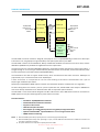
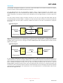
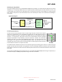
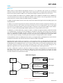
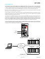
EOT-4581
Ethernet to Optical Fibre Transceiver
User Manual
IRT Electronics Pty Ltd | www.irtelectronics.com
Page 1 of 14
Revision 00
EOT-4581
Ethernet to Optical Fibre Transceiver
Revision History:
Revision
00
Date
27/11/2014
By
AL
Change Description
Original Issue.
Applicable to:
Firmware ≥
Revision 1.0
IRT Electronics Pty Ltd | www.irtelectronics.com
Page 2 of 14
Revision 00
EOT-4581
USER MANUAL
Table of Contents:
Section
Page
Revision History
Operational Safety
General Description
Technical Specifications
Configuration
Installation
Ethernet Connection
Fibre Connections
Alarm Connections
Front & Rear Panel Connector Diagrams
Operation
Interfacing to a Gig-E Switch
Front Panel LED Indicators
SNMP – What Is It?
EOT-4581 SNMP Functions
Maintenance & Storage
Warranty & Service
2
4
5
6
7
7
7
7
7
8
9
10
10
11
13
14
14
This instruction book applies to units fitted with firmware ≥ Revision 1.0.
IRT Electronics Pty Ltd | www.irtelectronics.com
Page 3 of 14
Revision 00
EOT-4581
OPERATIONAL SAFETY
WARNING
Operation of electronic equipment involves the use of voltages and currents that
may be dangerous to human life. Note that under certain conditions dangerous
potentials may exist in some circuits when power controls are in the OFF position.
Maintenance personnel should observe all safety regulations.
Do not make any adjustments inside equipment with power ON unless proper
precautions are observed. All internal adjustments should only be made by suitably
qualified personnel. All operational adjustments are available externally without
the need for removing covers or use of extender cards.
Optical Safety
The light emitted from the LASER diode used in this system is
invisible and may be harmful to the human eye. Avoid looking
directly into the fibre optic cable or connectors or into the
collimated beam along their axis when the device is in operation.
Operating the LASER diode outside of its maximum ratings may
cause device failure or a safety hazard.
DANGER
Invisible LASER radiationAvoid direct exposure to beam
Peak power
Wavelength
2 mW
1270–1610nm
Class 1 LASER Product
IRT Electronics Pty Ltd | www.irtelectronics.com
Page 4 of 14
Revision 00
EOT-4581
GENERAL DESCRIPTION
BLOCK DIAGRAM EOT-4581 SIGNAL PATH
EOT-4581
EOT-4581
10/100/1000
Bi-directional
Ethernet
Port 1
Rx Fibre I/P
Tx Fibre O/P
Ethernet I/O
Fibre Link
9-30dB1,3
path loss
Ethernet I/O
Tx Fibre O/P
Rx Fibre I/P
SNMP
10/100/1000
Bi-directional
Ethernet
Port 2
SNMP
rd
3 Party
Gig-E Switch
with
1000 Base-X
Optical
Interface
Multi
Bi-directional
Ethernet
Ports
The EOT-4581 transceiver module is designed principally for use as a 10/100/1000 Base-T Ethernet to fibre optic
1
transmission link, using 9/125μm single mode fibre, with optical paths losses up to 30dB .
The EOT-4581 conforms to the IEEE 802.3i, 802.3y and 802.3ab standards for Ethernet over CAT-5 cable, and the
IEEE 802.3z (1000 Base-X) standard for Gigabit Ethernet over optical fibre.
The Ethernet port has automatic MDI/MDI-X detection, this detects whether the Ethernet interconnect cable is a
straight through or cross over type and automatically switches itself to accommodate, and will automatically select
the link speed of the connected network (10/100/1000 Mb/s).
The EOT-4581 is also able to support Jumbo frames, which are Ethernet frames with more than 1500 bytes of
payload data, up to a maximum frame size of 10,240 bytes.
A fibre transceiver is incorporated on the one card allowing bi-directional communication over a pair of
SC/PC single mode fibre optic cables.
1,2
Optionally a 1310/1550nm WDM optical combiner can be fitted to allow for combined use on a single fibre.
As well as being able to be used as a pair for a point to point fibre link, the EOT-4581‘s fibre output is 1000 Base-X
and can be directly interfaced into an Ethernet switch with an equivalent optical interface.
The EOT-4581 is a Eurocard module designed to fit IRT’s 1RU frame or IRT’s 4000 series frames for use with IRT’s
SNMP system and may be used alongside any other of IRT’s Eurocards.
Standard features:
• Suitable for 10/100/1000 Base-T Ethernet.
• Standard RJ-45 CAT-5 Ethernet connection.
• Supports Jumbo frames.
• 1000 Base-X optical interface.
• Path lengths up to 30dB optical path loss using 9/125μm single mode fibre.
• Optional on-board WDM1, 2 optical combiner for use on a single common fibre.
• SNMP software monitoring.
NOTE: 1
2
3
With the WDM option fitted, optical path loss is reduced by approximately 2dB.
With the WDM option fitted, when operating as a pair, one EOT-4581 must be fitted with a 1310nm transceiver and
the other a 1550nm transceiver.
An optical attenuator is required for optical path losses <9dB.
IRT Electronics Pty Ltd | www.irtelectronics.com
Page 5 of 14
Revision 00
EOT-4581
TECHNICAL SPECIFICATIONS
Ethernet:
Type
Data Rate
Maximum Frame Size
Connector
Optical:
Type
Data Rate
4, 5
Optical Path Loss
Optical Fibre
Optical Wavelength
Standard IEEE 802.3i, 802.3y & 802.3ab
10/100/1000 Mb/s, automatic.
10,240 bytes.
RJ-45.
Optical Output
Optical Input
Standard 802.3z (1000 Base-X).
1000 Mb/s.
9 to 30 dB.
Designed for use with 9/125μm single mode fibre.
1310nm (standard);
1470nm, 1490nm, 1510nm, 1530nm, 1550nm, 1570nm, 1590nm or 1610nm
available.
Dual SC/PC (standard);
Single SC/PC (WDM version).
0 dBm +4.5/-0 dB DFB laser.
APD detector (standard), -9 to -30 dBm input level.
Power Requirements:
Voltage
Power consumption
28 Vac CT (14-0-14) or ± 16 Vdc.
< 2.5 VA.
Optical Connectors
Other:
Temperature range
Mechanical
Finish
Front panel
Rear assembly
Dimensions
Ordering:
EOT-4581
EOT-4581/xxxx
0 - 50° C ambient.
For mounting in IRT 19" rack chassis with input, output and power connections
on the rear panel.
Grey, black lettering & red IRT logo.
Detachable silk-screened PCB with direct mount connectors to Eurocard and
external signals.
6 HP x 3 U x 220 mm IRT Eurocard.
EOT-4581/1310/WDM
EOT-4581/1550/WDM
Standard EOT-4581 fitted with 1310nm laser.
EOT-4581 fitted with laser other than 1310nm where xxxx = wavelength required
(e.g. EOT-4581/1550 is fitted with a 1550nm laser).
EOT-4581 fitted with WDM and 1310nm laser.
EOT-4581 fitted with WDM and 1550nm laser.
NOTE: 4
5
Optical attenuator required for EOT-4581 when optical path loss is less than 9dB.
Optical path loss reduced by approximately 2dB when WDM option fitted.
Due to our policy of continuing development, these specifications are subject to change without notice.
IRT Electronics Pty Ltd | www.irtelectronics.com
Page 6 of 14
Revision 00
EOT-4581
CONFIGURATION
There are no configuration settings for the EOT-4581.
INSTALLATION
Pre-installation:
Handling:
This equipment may contain or be connected to static sensitive devices and proper static free handling precautions
should be observed.
Where individual circuit cards are stored, they should be placed in antistatic bags. Proper antistatic procedures
should be followed when inserting or removing cards from these bags.
Installation in frame or chassis:
See details in separate manual for selected frame type.
Ethernet Connection:
The Ethernet port is accessible via the rear assembly and is fitted with a standard RJ-45 connector suitable for
either crossover or non-crossover standard CAT5 Ethernet cables. This port connects directly to an Ethernet link, or
via an Ethernet router or Ethernet switch and will automatically set itself to match the input data rate of 10Mb/s,
100Mb/s or 1000Mb/s.
Green LED’s on the Ethernet connector illuminate when an optical link and an Ethernet link have been established.
Optical Link LED
Ethernet Link LED
Fibre Connections:
Optical connections are made via SC/PC (standard) terminated single mode fibre directly to the rear of the main
card accessible via the rear assembly. Care should be taken when removing the card either by disconnecting the
optical cables first or allowing enough slack for the optical cable to pass through the frame. The top optical
connector is the optical transmitter output and the lower optical connector is the optical receiver input.
If the card has been fitted with the WDM option, both optical transmit and receive signals are combined on a
single SC/PC fibre. When operating the WDM option, one unit must be fitted with a 1310nm transceiver and the
other must be fitted with a 1550nm transceiver.
For path lengths <9dB for an APD type of transceiver, or <3dB for a PIN type of transceiver, an optical attenuator
(supplied) must be used in the path to avoid overloading the optical detector else damage to the detector itself
may result.
Alarm Connections:
The external alarm contact connections are made to the 4 pin phoenix style connector on the rear assembly. On an
alarm condition relay contacts go open circuit, that is switch open with respect to ground.
The connections being:
1
2
3
4
GND.
GND.
Optical Alarm.
Ethernet Alarm.
A Optical alarm is designated as a laser or optical input fail alarm.
A Ethernet alarm is designated as an Ethernet input is missing.
IRT Electronics Pty Ltd | www.irtelectronics.com
Page 7 of 14
Revision 00
EOT-4581
Front & Rear Panel Connector Diagrams:
Alarm
O/P
Alarm
O/P
Tx O/P
Tx/Rx
Rx I/P
Standard
WDM Option
IRT Electronics Pty Ltd | www.irtelectronics.com
Page 8 of 14
Revision 00
EOT-4581
OPERATION
The EOT-4581 is designed to operate as a pair with a second EOT-4581. Each unit does the Ethernet to Optical
conversion and the reciprocal Optical to Ethernet conversion.
The EOT-4581 Ethernet port will automatically configure itself to match the Ethernet link, whether it be
10/100/1000 Mb/s rate. It also automatically sets itself up for MDI or MDI-X operation, so there are no setup
options required for connecting to an Ethernet link allowing the use of straight through or crossover cables to be
used.
The laser output connector (upper connector) connects at one end of a single mode fibre fitted with the
corresponding fibre connector (SC/PC - standard). The other end of the fibre connects to another EOT-4581 into
the receiver input connector (lower connector). Likewise the reverse is true with a second fibre to supply the
return path.
Application Diagram:
Optic Fibre
9-30dB Path Loss
EOT-4581
Bi-directional
Ethernet
Port 1
EOT-4581
Tx O/P
Tx O/P
Rx I/P
Optic Fibre
9-30dB Path Loss
Rx I/P
Bi-directional
Ethernet
Port 2
NOTE: Optical attenuator required if path loss < 9dB for APD detector
or < 3dB for PIN detector.
Alternatively it is possible to run bi-directionally on a single fibre if the two EOT-4581’s are fitted with the optional
WDM optical Mux and each have a different wavelength laser fitted, namely 1310nm and 1550nm Alternative the
standard version cards can be run through an external CWDM optical Mux. Standard optical connector for the
WDM version is SC/PC.
Application Diagram:
Bi-directional
Ethernet
Port 1
EOT-4581
/1310/WDM
(1310nm)
Optic Fibre
7-28dB Path Loss
Fibre I/O
EOT-4581
/1550/WDM
(1550nm)
Fibre I/O
Bi-directional
Ethernet
Port 2
NOTE: Optical attenuator required if path loss < 7dB for APD detector
or < 1dB for PIN detector.
For path lengths <9dB optical loss when using an APD detector, or <3dB optical loss when using a PIN detector, an
optical attenuator is required. The length of fibre that this corresponds to depends on the fibre loss characteristics
at the relevant wavelength of the laser module chosen. For example, if the fibre loss characteristic of the chosen
fibre is 0.2dB per kilometre at 1550 nm, say, then the maximum distance that can be run is 150 km
(30dB/0.2dBkm), although connector losses, such as through patch lead connectors etc., should also be taken into
consideration when calculating maximum distances. Actual attenuation versus wavelength characteristics depends
upon optic fibre manufacturer’s own specifications. Also a few dB headroom is recommended to allow for the
effects of laser aging over time.
IRT Electronics Pty Ltd | www.irtelectronics.com
Page 9 of 14
Revision 00
EOT-4581
Interfacing to a Gig-E Switch:
The optical output conforms to the IEEE 802.3z (1000 Base-X) standard. This allows the EOT-4581 card to directly
rd
interface to a 3 party Gig-E Switch that has an optical I/O port conforming to the same standard. As such, only
one EOT-4581 card is required. The advantage of this is an Ethernet connection can be added to an existing system
that is too far away than can be connected by CAT5 or CAT 6 twisted pair cable, such as between two buildings or
across town.
Application Diagram:
Optic Fibre Path Loss
dependent upon
Gig-E Switch specs.
EOT-4581
Bi-directional
Ethernet
Port
Tx O/P
Rx I/P
rd
3 Party
Gig-E Switch
with
1000 Base-X
Optical
Interface
Multi
Bi-directional
Ethernet
Ports
NOTE: Optical attenuator required if path loss < 9dB for APD detector, or < 3dB for
PIN detector, for EOT-4581, and also dependent upon Gig-E Switch specs.
Front Panel LED Indicators:
The OPT LED will illuminate green when an optical signal has been received. If the optical
input level is approaching or has exceeded its threshold limit, this LED will flash green to
indicate an Optical Low state. The Optical Low trigger point can vary between the plug-in
receivers, so if operating at signal paths close to the recommended maximum specified
threshold confirmation of the Quality of Service should be checked. No illumination
indicates that there is no optical link established, either there is no input present or the
input signal is far below its recommended operating range. The left LED on the rear
assembly’s Ethernet connector will also illuminate when an optical signal has been received,
but this LED will not flash on an Optical Low state.
OPT
LINK
10
100
1000
EOT-4581
The LINK LED down indicates the presence of an Ethernet signal by illuminating green. If there is no Ethernet signal
present, this LED will not illuminate. The right LED on the rear assembly’s Ethernet connector will also illuminate
green when an Ethernet connection has been detected, but this LED does not indicate what Ethernet rate has been
connected.
The 10, 100 and 1000 LEDs will illuminate green for a connected 10/100/1000 Mb/s Ethernet signal respectively. In
the shown example, a 100Mb/s (FAST) Ethernet signal has been connected.
IRT Electronics Pty Ltd | www.irtelectronics.com
Page 10 of 14
Revision 00
EOT-4581
SNMP
What Is It?
SNMP stands for Simple Network Management Protocol. It is an application layer protocol for managing IP
(Internet Protocol) based systems. SNMP enables system administrators to manage system performance, and to
find and solve system problems. SNMP runs over UDP (User Datagram Protocol), which in turn runs over IP.
Three types of SNMP exist: SNMP version 1 (SNMPv1), SNMP version 2 (SNMPv2) and SNMP version 3 (SNMPv3). It
is not the intention here to discuss the differences between various versions, only to bring attention to the fact
that IRT Electronics modules, fitted with SNMP capability, use SNMPv1.
An SNMP managed network consists of three key components: Network Management Systems (NMS), agents, and
managed devices.
An NMS is the console through which the network administrator performs network management functions, such
as monitoring status (e.g. alarm states) and remote controlling, of a set of managed devices. One or more NMS’s
must exist on any managed network. Generally the NMS is a computer running third party SNMP control software.
There are a number of third party SNMP software applications currently available on the market.
An NMS polls, or communicates with, an agent. An agent is a network management software module that resides
in a managed device. An agent has local knowledge of management information and translates that information
into a form compatible with SNMP. The agent, therefore, acts as an interface between the NMS and the managed
devices. The NMS sends a request message, and control commands for the managed devices, to the agent, which
in turn sends a response message, containing information about the managed devices, back to the NMS.
A managed device contains an SNMP agent and resides on a managed network. Managed devices collect and store
management information and make this information available to NMS’s using SNMP.
Managed device agent variables are organised in a tree structure known as a Management Information Base
(MIB). Within the MIB are parameters pertaining to the managed device. An Object Identifier (OID) number within
the MIB defines the managed device type. This is a unique number specific to the model of managed device. Other
information relating to the device is also stored, information such as alarm states, controllable settings, etc. The
MIB tree is organised in such a way that there will be no two MIB files with conflicting placements.
Normally an NMS polls an agent for information relating to the MIB in a managed device to be sent back to the
NMS. When certain conditions are met within the MIB, such as major alarm conditions, for example, the agent
automatically sends what is known as a trap to the NMS without any prompting from the NMS. This allows
automatic notification of a predetermined event.
SNMP Block Diagram
NMS
IP
Network
NMS
SNMP Agent
Protocol Engine
MIB
SNMP Agent
SNMP Agent
Protocol Engine
MIB
SNMP Agent
SNMP Agent
Protocol Engine
MIB
SNMP Agent
IRT Electronics Pty Ltd | www.irtelectronics.com
Page 11 of 14
Revision 00
EOT-4581
SNMP with IRT Products:
IRT Electronics currently employs SNMPv1 with its SNMP capable frames. The frame acts as an agent when fitted
with a CDM-xxxx module. This module has its own designated slot next to the power supply so as to not affect the
number of modules that the frame will take. Communication between the NMS, the frame and its loaded modules
are via this CDM-xxxx module. Note that the NMS software is third party and not supplied by IRT Electronics.
Ethernet connection for SNMP operation is via an RJ45 connector on the rear of the frame, below the mains inlet.
Ethernet rate runs at either 10 baseT or 100 baseT.
Frame parameters, such as Name, Address and Location, are set via an RS232 interface, a D9 connector on the rear
of the frame below the mains inlet. A software terminal emulator, such as Tera Term or HyperTerminal, is used for
setting and reading the parameters of the frame.
IRT modules that are SNMP compatible may need an optional plug-in SNMP module with a program relevant to the
module that it is plugged into. Depending on the module, besides the module identification, parameters such as
alarm states, inputs and controls etc. are communicated to the CDM-xxxx agent via a data bus on the rear of the
frame. Thus the CDM-xxxx collects information on what is loaded within the frame, what positions they occupy,
and their current status for communication to the NMS when the NMS sends a request for information.
In the event of a major alarm from any of the SNMP compatible modules, or power supplies, a trap is automatically
sent by the CDM-xxxx agent to the NMS without any prompting by the NMS. This alerts the operator to any fault
conditions that may exist that need immediate attention.
110/240 V 50/60 Hz
0.7 A (max.)
FRU-4000
FRAME
FUSES
220/240 Vac
500 mA S.B.
110/120 Vac
1A S.B.
RS232
Alarm
Ethernet
+
48Vdc
AS3260 approval no.: CS6346N
Ass. no.: 804692
IRT SNMP Connections
NMS
Ethernet Cable
IP
Network
IRT modules fitted
with SMU-4000
CDM-xxxx
PSU’s
IRT SNMP Frame
Ethernet Cable
IRT modules fitted
with SMU-4000
CDM-xxxx
PSU’s
IRT SNMP Frame
Ethernet Cable
IRT SNMP Setup
IRT Electronics Pty Ltd | www.irtelectronics.com
Page 12 of 14
Revision 00
EOT-4581
EOT-4581 SNMP Functions:
The following SNMP functions are capable of being controlled and monitored by an NMS:
sysDescr
- A description of the unit:
EOT-4581 Ethernet to Optical Transceiver
sysObjectID
- Object identifier:
irtEOT4581
sysUpTime
- A indication of how long the unit has been running since its last power on or reset in
Days, Hours, Minutes and Seconds.
sysName
- A 16 character writable system name. Default set name:
EOT-4581
sfpType
- An indication of the detected plug-in SFP module:
(1) transceiver: Transceiver module detected. Should indicate this.
(2) notDetected: No plug-in SFP detected.
(3) unknownSFP: Unable to determine the type of plug-in SFP module.
sfpReceiverType
- An indication of the transceiver’s detector type:
(1) unknown: Unable to determine the type of detector.
(2) apd: APD detector fitted.
(3) pin: PIN detector fitted.
sfpwavelength
- An indication of the transceiver’s wavelength.
opticalLink
- An indication of the transceiver’s optical input:
(1) connected: Good optical level received.
(2) disconnected: No optical input detected – either not connected or path length is
too great.
(3) lowPower: Optical detector of receiver is reporting that the optical input signal is
approaching its minimum, or has exceeded its, allowable signal strength.
NOTE: Detectors can vary in their reporting of optical low state. It is
recommended to confirm that the received signal is error free if a lowPower
alarm has been raised.
ethernetLink
- An indication of the status of the Ethernet link:
(1) connected: Ethernet signal connected.
(2) disconnected: No Ethernet signal is detected.
ethernetRate
- An indication of the data rate of the Ethernet link:
(1) 10Mbs: 10Mb/s Ethernet data rate connected.
(2) 100Mbs: 100Mb/s (FAST) Ethernet data rate connected.
(3) 1Gbs: 1000Mb/s (Gig-E) Ethernet data rate connected.
(4) unknown: Unknown data rate or no connection.
softwarever
- An indication of the software revision of this card.
reset
- Unit reset control:
(0) normal: when queried reset control returns a ‘normal’ message.
(1) reset: Setting a 1 causes a reset of the card.
generalAlarmTrap
- An indication and control of Trap enable/disable function:
(1) enable: Enable general alarm Trap.
(2) disable: Disable general alarm Trap.
IRT Electronics Pty Ltd | www.irtelectronics.com
Page 13 of 14
Revision 00
EOT-4581
MAINTENANCE & STORAGE
Maintenance:
No regular maintenance is required.
Care however should be taken to ensure that all connectors are kept clean and free from contamination of any
kind. This is especially important in fibre optic equipment where cleanliness of optical connections is critical to
performance.
Storage:
If the equipment is not to be used for an extended period, it is recommended the whole unit be placed in a sealed
plastic bag to prevent dust contamination. In areas of high humidity a suitably sized bag of silica gel should be
included to deter corrosion.
Where individual circuit cards are stored, they should be placed in antistatic bags. Proper antistatic procedures
should be followed when inserting or removing cards from these bags.
WARRANTY & SERVICE
Equipment is covered by a limited warranty period of three years from date of first delivery unless contrary
conditions apply under a particular contract of supply. For situations when “No Fault Found” for repairs, a
minimum charge of 1 hour’s labour, at IRT’s current labour charge rate, will apply, whether the equipment is
within the warranty period or not.
Equipment warranty is limited to faults attributable to defects in original design or manufacture. Warranty on
components shall be extended by IRT only to the extent obtainable from the component supplier.
Equipment return:
Before arranging service, ensure that the fault is in the unit to be serviced and not in associated equipment. If
possible, confirm this by substitution.
Before returning equipment contact should be made with IRT or your local agent to determine whether the
equipment can be serviced in the field or should be returned for repair.
The equipment should be properly packed for return observing antistatic procedures.
The following information should accompany the unit to be returned:
1.
2.
3.
4.
5.
6.
7.
A fault report should be included indicating the nature of the fault
The operating conditions under which the fault initially occurred.
Any additional information, which may be of assistance in fault location and remedy.
A contact name and telephone and fax numbers.
Details of payment method for items not covered by warranty.
Full return address.
For situations when “No Fault Found” for repairs, a minimum charge of 1 hour’s labour will apply,
whether the equipment is within the warranty period or not. Contact IRT for current hourly rate.
Please note that all freight charges are the responsibility of the customer.
The equipment should be returned to the agent who originally supplied the equipment or, where this is not
possible, to IRT directly. Details of IRT’s direct address can be found at IRT Electronics’ website.
Web address: www.irtelectronics.com
Email: [email protected]
IRT Electronics Pty Ltd | www.irtelectronics.com
Page 14 of 14
Revision 00