1
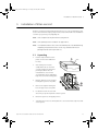
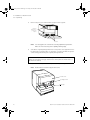
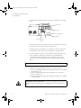
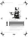
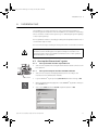
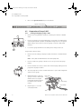
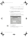
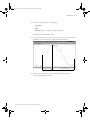
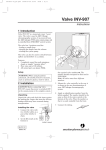
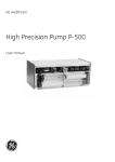
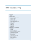
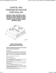
18116223_microLC.book Page 1 Friday, June 30, 2006 2:09 PM
GE Healthcare
Ettan MicroLC
Installation Guide
18116223_microLC.book Page 2 Friday, June 30, 2006 2:09 PM
18116223_microLC.book Page 3 Friday, June 30, 2006 2:09 PM
Important user information
All users must read this entire manual to fully understand the safe use of
Ettan MicroLC.
WARNING!
The WARNING! sign highlights instructions that must be followed to avoid personal injury. It is important not to proceed until all stated conditions are met and clearly
understood.
CAUTION!
The Caution! sign highlights instructions that must be followed to avoid
damage to the product or other equipment. It is important not to proceed
until all stated conditions are met and clearly understood.
Note
The Note sign is used to indicate information important for trouble-free
and optimal use of the product.
CE Certifying
This product meets the requirements of applicable CE-directives. A copy of
the corresponding Declaration of Conformity is available on request.
The CE symbol and corresponding declaration of conformity, is valid for
the instrument when it is:
– used as a stand-alone unit, or
– connected to other CE-marked GE Healthcare
instruments, or
– connected to other products recommended or
described in this manual, and
– used in the same state as it was delivered from
GE Healthcare except for alterations described in this
manual.
Recycling
This symbol indicates that the waste of electrical and electronic equipment must not be disposed as unsorted municipal waste and must be collected separately. Please contact
an authorized representative of the manufacturer for information concerning the decommissioning of equipment.
WARNING!
This is a Class A product. In a domestic environment this product may
cause radio interference in which case the user may be required to make
adequate measures.
18116223_microLC.book Page 4 Friday, June 30, 2006 2:09 PM
18116223_microLC.book Page 5 Friday, June 30, 2006 2:09 PM
Contents
Contents
1
About this installation guide
2
Safety
3
Pre-requisites
4
Installation overview
5
Installation of Ettan microLC
5.1 Unpacking ...................................................................................................................15
5.2 Installing the computer and the UniNet cables..........................................20
5.3 Connecting the mains cables ............................................................................21
6
Installation test
6.1
6.2
6.3
6.4
6.5
6.6
7
Start up the Ettan microLC system ..................................................................23
Preparation of Pump P-905 .................................................................................24
Preparation for the installation test .................................................................26
Running the installation test method .............................................................27
Evaluating the installation test results ...........................................................30
Correcting faulty evaluation results ................................................................32
Test record
7.1 Gradient test result .................................................................................................33
7.2 Step response test result.......................................................................................33
7.3 Autosampler peak test result..............................................................................33
8
Installation record
9
Registration form
Ettan microLC Installation Guide 18-1162-23 Edition AB
5
18116223_microLC.book Page 6 Friday, June 30, 2006 2:09 PM
Contents
6
Ettan microLC Installation Guide 18-1162-23 Edition AB
18116223_microLC.book Page 7 Friday, June 30, 2006 2:09 PM
About this installation guide 1
1
About this installation guide
TM
IMPORTANT! Ettan microLC is intended for laboratory use only, not for
clinical or in vitro use, or for diagnostic purposes.
Ettan microLC is assembled and fully tested before shipping.
For safe transportation, however, some components have been secured and thus
need to be detached before the system can be tested and used. Cables, capillaries,
accessories, etc. are enclosed in paper boxes.
This guide describes how to install Ettan microLC. The guide is divided into two
parts; one describing the installation and one describing how to run the
installation test. After the installation procedure has been performed, your Ettan
microLC is ready for purification work.
For full details of specifications, methods, maintenance etc., refer to the respective
User Manuals and Instructions.
Ettan microLC Installation Guide 18-1162-23 Edition AB
7
18116223_microLC.book Page 8 Friday, June 30, 2006 2:09 PM
1 About this installation guide
8
Ettan microLC Installation Guide 18-1162-23 Edition AB
18116223_microLC.book Page 9 Friday, June 30, 2006 2:09 PM
Safety 2
2
Safety
•
The system is designed for indoor use only.
•
Do not use in a dusty atmosphere or close to spraying water.
Refer to Technical Specifications in the System Manual for detailed environmental
pre-requisites.
WARNING! The Ettan microLC system operates under high pressure. Eye
protection must be worn at all times.
WARNING! The individual modules must not be opened by the user. They
contain high voltage circuits that can give a lethal electric shock.
WARNING! Monitor UPC-900 uses high intensity ultra-violet light. Do not
disconnect the optical unit while the lamp is ON.
WARNING! Ettan microLC must be connected to a grounded mains socket.
WARNING! There must always be a sample loop connected to ports 2 and 6 of
the injection valve. This prevents liquid spraying out of the ports when
switching the valve, which is especially dangerous if hazardous chemicals are
being used.
WARNING! Two people are required to lift the system.
WARNING! Never block the flowpath outlet, since this will create overpressure and may result in injury.
WARNING! Only spare parts approved or supplied by GE Healthcare may be
used for maintaining and servicing the system.
WARNING! Never place waste containers on the top of the system. If they
become full and overflow, liquid may penetrate the system causing a shortcircuit.
WARNING! When using hazardous chemicals, take all suitable protective
measures, such as wearing protective glasses and gloves resistant to the
chemicals used. Follow local regulations and instructions for safe operation
and maintenance of the system.
Ettan microLC Installation Guide 18-1162-23 Edition AB
9
18116223_microLC.book Page 10 Friday, June 30, 2006 2:09 PM
2 Safety
10
Ettan microLC Installation Guide 18-1162-23 Edition AB
18116223_microLC.book Page 11 Friday, June 30, 2006 2:09 PM
Pre-requisites 3
3
Pre-requisites
WARNING! Ettan microLC must be connected to a grounded mains socket.
•
Two people are recommended to lift Ettan microLC onto the working bench.
•
To install Ettan microLC, a working area of about 200 x 80 cm is required.
•
Ettan microLC requires 100–120/220–240 VAC, 50/60 Hz electrical supply
with safety grounding.
•
Cutting pliers are recommended for cutting plastic straps.
•
A waste flask.
The installation test requires the following solutions:
•
200 ml of distilled water for priming and purging the pump.
•
100 ml of 0.4% acetone in distilled water.
•
100 ml of 20% ethanol in distilled water.
•
10 mg of Uracil Biopur (18-1160-37, 10 g/pack).
Ettan microLC Installation Guide 18-1162-23 Edition AB
11
18116223_microLC.book Page 12 Friday, June 30, 2006 2:09 PM
3 Pre-requisites
12
Ettan microLC Installation Guide 18-1162-23 Edition AB
18116223_microLC.book Page 13 Friday, June 30, 2006 2:09 PM
Installation overview 4
4
Installation overview
•
Unpack Ettan microLC page 15
•
Unpack and install the computer and the UniNet cables page 20
•
Connect mains power cabling page 21
•
Complete the first two sections of the installation record page 35
•
Start up the Ettan microLC system page 23
•
Prepare Ettan microLC for the installation test page 26
•
Run the installation test method page 27
•
Evaluate the gradient page 31
•
Evaluate the step response page 31
•
Evaluate the autosampler peaks page 31
•
Complete the test record page 33
•
Complete the registration form page 37
•
Complete the final section of the installation record page 35
•
Store photocopies of all records and forms in the
System Logbook.
•
Store the Installation Guide in the User Manual box.
Ettan microLC Installation Guide 18-1162-23 Edition AB
13
18116223_microLC.book Page 14 Friday, June 30, 2006 2:09 PM
4 Installation overview
14
Ettan microLC Installation Guide 18-1162-23 Edition AB
18116223_microLC.book Page 15 Friday, June 30, 2006 2:09 PM
Installation of Ettan microLC 5
5
Installation of Ettan microLC
Begin by creating a clean and dry working area of 200 × 80 cm that allows easy
access. Then follow the step-by-step instructions below and fill in the installation
record as you go along, see page page 35.
Note: Some components are packed in Accessory Box E1.
Note: Some packing lists are included in the paper boxes.
Note: It is important that the filters, flow cells and lamps are not handled during
unpacking. For protection of these items, they should remain in their
packing materials until required for use.
5.1
1
Unpacking
Cut the straps and remove the
plastic foil from the cardboard
hood (1).
2
After having removed the
cardboard hood (1), check the
contents against the attached
packing list. Check also all
included boxes. Store all the
enclosed paper boxes and plastic
bags in a convenient nearby place.
3
Release and remove the strap (2)
holding the system to the pallet.
1
Straps
3
2
4
Remove the staples holding the
bottom support (3) to the pallet.
5
Lift Ettan microLC onto the work
area. Two people are required to lift the system.
6
Raise the system to an upright position.
7
Turn Ettan microLC on its swivel platform to access the fluid component side
of the system.
Ettan microLC Installation Guide 18-1162-23 Edition AB
15
18116223_microLC.book Page 16 Friday, June 30, 2006 2:09 PM
5 Installation of Ettan microLC
5.1 Unpacking
8
Remove the protective foam and the straps from the system.
Cut here
and remove
protective
foame
Cut here
Note: Use cutting pliers. Be careful not to cut any capillaries by accident.
Make sure not to lose any of the capillary marking tags.
9
Save all the original packing material. If, for any reason, the equipment has to
be repacked, for transportation or otherwise, it is important that the system
can be safely packed using the original packing material.
CAUTION! Do not lift the Ettan microLC by the valves on the side. Instead
grasp the unit firmly in the gap between the swivel platform and the base of
the main unit and lift.
10 Unpack the Autosampler A-905 and place it on top of the system.
Note: Do NOT lift the instrument by the front cover.
Front cover
Locking screw
Red cap
16
Ettan microLC Installation Guide 18-1162-23 Edition AB
18116223_microLC.book Page 17 Friday, June 30, 2006 2:09 PM
Installation of Ettan microLC 5
The Autosampler A-905 has two transportation safety devices which must be
removed:
•
Remove the locking screw holding the front cover. It is located at the right
side of the front cover, see figure above. Save the locking screws.
•
A red plastic cap is attached over the needle washing mechanism below
the front cover, see figure above. Remove the plastic cap and save it.
CAUTION! Make sure that none of the ventilation holes are blocked. Blockage
of the ventilation holes can cause malfunctioning of the Autosampler A-905 or
even damage the electronics.
11 Unpack the microplate base and put it in place. At this stage, its position is not
critical.
Waste solvent bottle
Microplate base
12 Unpack the waste solvent bottle and attach it to the Autosampler A-905, and
insert the related tubing.
13 Unpack the Accessory Box E1. The box contains the following components
that should be attached to the system:
Ettan microLC Installation Guide 18-1162-23 Edition AB
17
18116223_microLC.book Page 18 Friday, June 30, 2006 2:09 PM
5 Installation of Ettan microLC
5.1 Unpacking
•
Flow cell holder UPC-900. Attach to the side of the valve box, see figure
below.
UV flow cell
Zn optics
Conductivity cell
Valve box
Flow cell holder
UPC-900
•
Zn optics with 214 nm filter. Attach to the Flow cell holder UPC-900 and
connect to the rear of the UPC-900, see figure above.
•
Conductivity cell 0.2 μl. Attach to the underside of the Flow cell holder
UPC-900 and connect to the rear of the UPC-900, see figure above.
•
UV flow cell 6/75 for the Micro flow configuration (default) or Fast micro
flow configuration, and UV flow cell 6/150 for the Standard flow
configuration. Attach the UV flow cell into the detector housing (no
specific flow direction) and tighten the screw underneath, see figure
above.
CAUTION! Handle the UV flow cell carefully.
•
Capillaries S5, S6, S8 for the Micro flow configurations. Attach the
capillaries by using fingertights and sleeves, see item 15 below.
1. Connect capillary S5 between the flow direction valve, port 6, and the
autosampler, port 6.
2. Connect capillary S6 between the autosampler, port 1, and the
injection valve, port 7.
3. Connect capillary S8 between the flow direction valve, port 4, and the
conductivity cell.
WARNING! RISK OF EYE INJURIES! The fused silica capillaries are strong and
flexible. However, if sharply bent, the capillary may split into small pieces of
glass.
18
Ettan microLC Installation Guide 18-1162-23 Edition AB
18116223_microLC.book Page 19 Friday, June 30, 2006 2:09 PM
Installation of Ettan microLC 5
Note: Avoid touching the capillary end. Proteins from your finger may harm
the measurements.
Note: Whenever attaching a silica capillary to a valve, ensure the capillary is
levelled with the sleeve as shown in the figure below. Do not push in the
silica capillary further; it may scratch the valve channel plate.
Fingertight
Sleeve
Silica capillary
Silica capillary
levelled with sleeve
•
Put the capillaries S5
and S6 in the slot on
the Autosampler A905 lid, see figure. A
piece of tape will hold
them in place.
14 Unpack the Contr. CU-900 PCI box. It contains the following:
•
PCI board
15 Unpack the Accessory kit Ettan microLC. It contains the following:
•
Mains power cable
•
UniNet cable
•
Fingertights and sleeves for the capillaries S5, S6 and S8
Ettan microLC Installation Guide 18-1162-23 Edition AB
19
18116223_microLC.book Page 20 Friday, June 30, 2006 2:09 PM
5 Installation of Ettan microLC
5.2 Installing the computer and the UniNet cables
5.2
1
Installing the computer and the UniNet cables
Unpack and install the computer and printer according to the manufacturer’s
instructions. Place them to the left of the system. Do not switch them on!
CAUTION! The mains power to Ettan microLC must be switched OFF before
the UniNet 1 cabling is installed.
2
Complete the UniNet 1 data communication chain by connecting a UniNet
cable between the computer and Pump P-905.
CAUTION! The UniNet connection to the computer MUST be made to the
board with four LEDs (1).
3
Connect a UniNet cable between one of the UniNet 1 sockets in the
autosampler and a UniNet 1 socket in the Monitor UPC-900,
see Fig 5-1.
1
All other UniNet 1 cables are connected at delivery.
An MS-unit used with the Ettan microLC system communicates through serial
standard cables with the computer. See the documentation of the MS-unit to
connect the unit.
20
Ettan microLC Installation Guide 18-1162-23 Edition AB
18116223_microLC.book Page 21 Friday, June 30, 2006 2:09 PM
Installation of Ettan microLC 5
UniNet 1
PC
Fig 5-1. Connecting UniNet 1 and mains cables.
5.3
Connecting the mains cables
WARNING! Ettan microLC must be connected to a grounded mains socket.
WARNING! Only use mains cables delivered or approved by GE Healthcare.
WARNING! In case of an emergency situation, the mains switch must always
be easy to access.
1
Connect a mains cable (2) supplied between Ettan microLC and a properly
grounded mains socket, see Fig 5-1. Do not switch on!
2
Connect a mains cable (3) between the autosampler and a mains socket at
the rear of Ettan microLC, see Fig 5-1.
3
Complete the two first sections of the Installation record on page 35.
The installation phase of Ettan microLC is now completed!
Ettan microLC Installation Guide 18-1162-23 Edition AB
21
18116223_microLC.book Page 22 Friday, June 30, 2006 2:09 PM
5 Installation of Ettan microLC
5.3 Connecting the mains cables
22
Ettan microLC Installation Guide 18-1162-23 Edition AB
18116223_microLC.book Page 23 Friday, June 30, 2006 2:09 PM
Installation test 6
6
Installation test
The installation test checks the function of the solvent delivery and the UV
monitoring system of Ettan microLC. The installation test can also be used at any
time to check the condition of the system, e.g. for calibrating the system regularly
or after a prolonged stop.
Correct gradient formation is tested by producing a linear gradient and a series of
concentration steps of Uracil.
Correct UV monitoring is tested by monitoring the Uracil concentration at 214 nm.
WARNING! When using hazardous chemicals, take all suitable protective
measures, such as wearing protective glasses and gloves resistant to the
chemicals used. Follow local regulations and instructions for safe operation
and maintenance of the system.
6.1
Start up the Ettan microLC system
6.1.1
1
Switch on the separation unit using the mains switch located to the left on the
base platform.
6.1.2
Mains switch
Start up the Ettan microLC separation unit
Start up the computer and the UNICORN software
1
Switch on the computer, the display and the printer according to the
instructions in the manufacturer manuals.
2
Log into Windows by first pressing Ctrl-Alt-Del, and then clicking on OK.
3
When the Windows desktop appears, start UNICORN by double-clicking on
the UNICORN icon.
4
Select user default and enter default as password. Click on OK.
TM
TM
Ettan microLC Installation Guide 18-1162-23 Edition AB
23
18116223_microLC.book Page 24 Friday, June 30, 2006 2:09 PM
6 Installation test
6.2 Preparation of Pump P-905
5
Click on the System Control button in the task bar.
System Control button
6.2
Preparation of Pump P-905
6.2.1
1
A
B
Priming and purging Pump P-905
1
Immerse the rinsing tubing in a flask (1) containing 20% ethanol in distilled
water.
2
Connect a syringe to the rinsing tubing that is connected to the underside (2)
of the left pump head on pump A. Slowly draw rinsing solution to the syringe.
When rinsing solution starts to enter the syringe, continue to draw a few
milliliters.
3
Loosen the syringe and immerse the tubing in the rinsing solution (1).
2
Purge Pump P-905 as follows:
1
Immerse the inlet tubing of all pump modules, with filters, in a distilled water
flask.
Note: Never place the flask below the level of the pump inlet.
2
Connect a male Luer syringe of about 30 ml to the open end of the purge
tubing.
3
Connect a male Luer connector at the other end of the purge tubing to the left
purge valve at pump module A.
4
Turn the purge valve counter clockwise half a turn to open it and slowly draw
eluent into the syringe.
5
When fluid starts to enter the
syringe continue to draw a few
milliliters before closing the
purge valve. Check that there is
no visible air left in the inlet
tubing.
Purge valve
Outlet tubing
Purge tubing
6
24
Repeat steps 3 to 5 for the
other pump heads.
Ettan microLC Installation Guide 18-1162-23 Edition AB
18116223_microLC.book Page 25 Friday, June 30, 2006 2:09 PM
Installation test 6
6.2.2
Setting compression compensation
When running Pump P-950 at high pressures, flow losses might occur due to the
compression of the eluent. Pump P-950 has functions that compensate for these
flow losses.
Note: The compensation functions should be activated at all times.
With the compensation function activated, the pump takes into consideration the
given compressibility for the liquid, at the actual pressure.
Some common values are given below:
Liquid
Value in Pa-1
Water
4.6 × 10
Methanol
12.1 × 10
Most other organic solvents, e.g. ethanol
11.0 × 10
-10
-10
-10
Before starting the installation test, make sure that the compensation value is set
-10
-1
to 4.6 × 10 Pa (for water).
To set the compression compensation:
Setup Compr. comp
(off)
off on
Setup Start comp.
(off)
off on
Setup Compr. value A
(4.6E-10) 4.6
Setup Compr. value B
(4.6E-10) 4.6
1
Select main menu Setup, press OK.
2
Select sub menu Setup Compr. comp, press OK.
3
Select On to activate the compensation. Press OK.
4
Select sub menu Setup Start comp, press OK.
5
Select On to activate the start compensation. Press OK.
6
Select sub menu Setup Compr. value A, press OK.
7
Enter compensation value 4.6 × 10
8
Select sub menu Setup Compr. value B, press OK.
9
Enter compensation value 4.6 × 10
Ettan microLC Installation Guide 18-1162-23 Edition AB
-10
-10
-1
Pa for pump module A.
-1
Pa for pump module B.
25
18116223_microLC.book Page 26 Friday, June 30, 2006 2:09 PM
6 Installation test
6.3 Preparation for the installation test
6.2.3
Testing pressure stability
Perform a pressure test to establish that all air has disappeared from the pump
heads. Perform as follows:
1
Make sure that inlet tubing A1 and B1 are immersed in a distilled water flask.
2
Connect a capillary between port 4 on the flow direction valve and the inlet of
the UV optical unit.
3
Run 0.2 ml/min at 0%B (distilled water). Check on the pump display that the
pressure reading is stable (variation < ±5%).
4
Run 0.2 ml/min at 100%B (distilled water). Check on the pump display that the
pressure reading is stable (variation < ±5%).
5
If the pressure is not stable, consult the Pump P-905 User Manual for troubleshooting instructions.
6
Click on END.
6.3
Preparation for the installation test
Installation Test Method Guide
26
Buffer A:
Distilled water
Buffer B:
7.5 mg/l Uracil in distilled water
Test flow rate:
300 μl/min
Test run time:
Approximately 48 minutes
1
Prepare a flask containing 100 ml of 7.5 mg/l Uracil in distilled water.
2
Fill the wells A1 and A2 in a 96-well low microplate.
3
Seal the microplate with a foil or a cap mat.
4
Immerse inlet tubing B1 into the rest of the Uracil solution.
5
Immerse inlet tubing A1 in a distilled water flask (>200 ml).
6
Fill a transport solvent vial with distilled water and seal it with a septum and
cap.
7
Put this vial in position 1 in the autosampler.
Ettan microLC Installation Guide 18-1162-23 Edition AB
18116223_microLC.book Page 27 Friday, June 30, 2006 2:09 PM
Installation test 6
8
In the System Control, make sure that plate type 96LOW is selected in Special
in System:Setting...
Note: It is also possible to fill two vials instead of using a microplate. Put the
vials in position A1 and A2 and select 48VIALS in System:Settings...
6.4
Running the installation test method
1
Start UNICORN as described in the Making your first run booklet, section 2.2,
UNICORN Overview.
2
The Toolbar guide is displayed after start-up. Click on Close.
3
Select File:Printer setup... from the Main Menu bar. Select the appropriate
printer from the list and select Landscape. Then click on OK to acknowledge
the printer chosen.
4
Return to the Main menu screen.
5
Click on the Instant Run button.
6
Select Installation Test in the templates list, and make sure that Any is
selected for both Technique: and For column:
Ettan microLC Installation Guide 18-1162-23 Edition AB
27
18116223_microLC.book Page 28 Friday, June 30, 2006 2:09 PM
6 Installation test
6.4 Running the installation test method
.
7
Click on Run.
8
When the Method window is shown, click on Next and then Next again.
9
Make sure that the compression compensation value for water,
-10
-1
4.6 × 10 Pa , is set in Pump P-905 (refer to section 6.2.2 Setting compression
compensation).
10 Click on Start to start the Installation test method.
Note: Irrelevant information may be de-selected by clicking in the Curves window
with the right mouse button, and then selecting Properties.
11 Click on the Curves tab.
28
Ettan microLC Installation Guide 18-1162-23 Edition AB
18116223_microLC.book Page 29 Friday, June 30, 2006 2:09 PM
Installation test 6
12 Select the following curves to be displayed:
•
UV_214nm
•
Conc.
•
Pressure (useful for trouble-shooting the system)
De-select all other highlighted curves.
13 The curves may now be monitored on the screen as the test progresses. The
installation test method run time is approximately 48 minutes.
100%
95%
70%
30%
5%
0%
Gradient result
Step response result
14 When the test is finished, the printer automatically prints out the
chromatogram and the test result.
Ettan microLC Installation Guide 18-1162-23 Edition AB
29
18116223_microLC.book Page 30 Friday, June 30, 2006 2:09 PM
6 Installation test
6.5 Evaluating the installation test results
6.5
Evaluating the installation test results
6.5.1
Automatic evaluation
The system automatically prints out the test result when the test is finished. The
print-out consists of a chromatogram and an evaluation of the test result.
•
If the gradient test result is OK, the print-out says
“Gradient linearity accepted”.
•
If the step response test result is OK, the print-out says
“Step response accepted”.
•
If the autosampler peaks test result is OK, the print-out says
“Autosampler peaks accepted”.
If any of the evaluated values falls outside the specified range, go to section 6.6
Correcting faulty evaluation results.
6.5.2
Manual evaluation
If you suspect that the automatic evaluation does not give a reliable result, a
manual evaluation can be done.
30
1
Minimise the run data window to access the Main menu.
2
Click on
in the results window and then double-click on the Installation
Test01 icon to open the result file.
3
Maximise the chromatogram window by clicking on
corner.
4
Click in the Curves window with the right mouse button and select Properties.
5
Click on the Curves tab and select the UV_214nm check box. Deselect the
other check boxes.
6
Press OK.
7
Double-click on
in the upper left corner of the chromatogram window
and read the absorbance for the steps corresponding to UV_214nm. Move
the vertical bar to the constant section of each plateau by dragging it. Enter
the absorbance values (in mAU) in column 2 in the Step response table of the
Test record (see page page 29), leaving out the decimals.
8
Click on Print under File to print out the chromatogram.
in the upper right
Ettan microLC Installation Guide 18-1162-23 Edition AB
18116223_microLC.book Page 31 Friday, June 30, 2006 2:09 PM
Installation test 6
Evaluating the gradient
Place a ruler along the gradient part of curve UV_214nm in the printed report.
The curve should be linear between 10% B and 90% B and void of discontinuities.
Evaluating the step response
Calculate the relative adsorption plateau heights for curve UV_214nm as follows:
1
Subtract the base line value (0% B) from each of the values in column 2 in the
Step response table of the Test record (see page page 29) and enter the
results in column 3.
2
Divide each value in column 3 by the base line corrected value corresponding
to 100% B, multiply by 100 and enter the results in column 4.
The values of column 4 should all fall within the intervals given in column 5.
Evaluating the autosampler peaks
1
In the printed report, read the Area and Area/Peak area% values for peaks no.
1 and 2.
2
Fill in the Test record.
3
Check that the values are within the given intervals.
Ettan microLC Installation Guide 18-1162-23 Edition AB
31
18116223_microLC.book Page 32 Friday, June 30, 2006 2:09 PM
6 Installation test
6.6 Correcting faulty evaluation results
6.6
Correcting faulty evaluation results
Should any of the evaluated values fall outside the specified range, proceed as
follows:
If the system differs from the standard configuration, evaluate the result
manually.
If the faulty evaluation result remains, continue below.
6.6.1
Faulty gradient
•
The mixer is faulty.
•
Disturbances – may arise from air in the pump, pump valves or bad sealings
in the pump. Refer to the Pump P-905 User Manual.
6.6.2
Faulty step response
•
If all values are faulty – air in the pump or a faulty pump.
•
5% and 95% faulty – bad sealing in the pumps (5% faulty = pump module B,
95% faulty = pump module A).
6.6.3
Faulty autosampler peak values
If values are faulty, make sure that the autosampler is properly purged and that
all tubing fittings are properly tightened.
32
Ettan microLC Installation Guide 18-1162-23 Edition AB
18116223_microLC.book Page 33 Friday, June 30, 2006 2:09 PM
Test record 7
7
Test record
Date: .....................................................
Ettan microLC serial no.: ..............................
7.1
Gradient test result
Gradient linear from .................. % B to .....................% B. (10 - 90%)
7.2
Step response test result
Step response table:
1
Programmed
Conc. %B
2
Value read
3
Baseline corrected
value
4
Normalised value
5
Allowed interval
100
95
94 – 96
70
69 – 71
30
29 – 31
5
4–6
0
7.3
Autosampler peak test result
Autosampler peak table:
1
Peak no.
2
Area
[mAU x min]
3
Area/Peak area
[%]
4
Allowed interval
[%]
1
66.1 – 67.2
2
32.8 – 33.9
Ettan microLC Installation Guide 18-1162-23 Edition AB
33
18116223_microLC.book Page 34 Friday, June 30, 2006 2:09 PM
7 Test record
7.3 Autosampler peak test result
34
Ettan microLC Installation Guide 18-1162-23 Edition AB
18116223_microLC.book Page 35 Friday, June 30, 2006 2:09 PM
Installation record 8
8
Installation record
Check
Sign
Remarks
1 Unpacking
•
Contents according to packing lists.
•
All packing material removed.
•
No visible damage.
2 Installation
•
Injection valve waste tubings (port 4 and 5, marked W1 and
W2) to waste reservoir.
•
Column holder installed.
•
Computer and printer installed.
•
UniNet 1 cabling installed.
•
Mains power cabling installed.
3 Installation test
•
Solutions prepared.
•
Tubings to piston seal rinsing system in 20% ethanol.
•
Ettan micro LC prepared.
•
Installation Test method run.
•
Installation Test results evaluated.
•
Test Record completed.
•
Registration Form completed.
•
Test Record and copy of Registration form stored in System
Logbook.
•
Registration form posted to Service Administration.
•
Installation Guide stored in User Manual box for future use.
Ettan microLC Installation Guide 18-1162-23 Edition AB
35
18116223_microLC.book Page 36 Friday, June 30, 2006 2:09 PM
8 Installation record
36
Ettan microLC Installation Guide 18-1162-23 Edition AB
18116223_microLC.book Page 37 Friday, June 30, 2006 2:09 PM
Registration form 9
9
Registration form
IMPORTANT!
WARRANTY REGISTRATION INFORMATION
Please ensure that this form is completed and returned to Service Administration
to register the users' equipment under warranty.
Name:
................................................................................................................................................................................
Institute/company: ......................................................................................................................................
Address: .........................................................................................................................................................
Department/location: .................................................................................................................................
Post Code: .....................................................................................................................................................
Phone Number: ........................................................ Fax Number: ..........................................................
End Users:.................................................................. E-mail: ......................................................................
Date of Installation: ................................................ Quote No: ................................................................
Customer Order No: ............................................... Invoice No: ...............................................................
Support Agreement purchased with the instrument:
Y/N
If YES give details:...................................................................................................................................
Installer (name): ......................................................................................................................................
Signature of Installer ............................................................................................................................
Installation Accepted: ................................................... Date:...........................................................
Note: Fill in serial numbers over-leaf.
Ettan microLC Installation Guide 18-1162-23 Edition AB
37
18116223_microLC.book Page 38 Friday, June 30, 2006 2:09 PM
9 Registration form
Components
Ettan microLC serial number: ........................................................................................................
QTY
Part Number
Description
Serial Number
System rack
Mixer M-925
Monitor UPC-900
Pump P-905
Autosampler A-905
Valve INV-917
Valve SV-903 (A)
Valve SV-903 (B)
Computer
Computer display
38
Ettan microLC Installation Guide 18-1162-23 Edition AB
18116223_microLC.book Page 39 Friday, June 30, 2006 2:09 PM
18116223_microLC.book Page 40 Friday, June 30, 2006 2:09 PM
www.gehealthcare.com
GE Healthcare Bio-Sciences AB
Björkgatan 30
751 84 Uppsala
Sweden
Ettan and UNICORN are trademarks of GE Healthcare companies.
GE, imagination at work and GE monogram are trademarks of General
Electric Company.
Windows is either a registered trademark or trademark of Microsoft
Corporation in the United States and/or other countries.
All goods and services are sold subject to the terms and conditions of sale of
the company within GE Healthcare which supplies them. GE Healthcare
reserves the right, subject to any regulatory and contractual approval, if
required, to make changes in specifications and features shown herein, or
discontinue the product described at any time without notice or obligation.
Contact your local GE Healthcare representative for the most current
information.
UNICORN Any use of this software is subject to GE Healthcare Standard Software End-User License Agreement for Life Sciences Software Products.
© 2006 General Electric Company – All rights reserved.
GE Healthcare Bio-Sciences AB, a General Electric Company.
GE Healthcare Bio-Sciences AB
Björkgatan 30, SE-751 84 Uppsala, Sweden
GE Healthcare Europe GmbH
Munzinger Strasse 5, D-79111 Freiburg, Germany
GE Healthcare UK Ltd
Amersham Place, Little Chalfont, Buckinghamshire, HP7 9NA, UK
GE Healthcare Bio-Sciences Corp
800 Centennial Avenue, P.O. Box 1327, Piscataway, NJ 08855-1327, USA
Asia Pacific Tel: +85 65 62751830 Fax: +85 65 62751829 • Australasia Tel: +61 2 8820 8299 Fax: +61 2 8820 8200 • Austria Tel: 01 /57606 1613 Fax: 01 /57606 1614 • Belgium Tel: 0800 73 890
Fax: 02 416 8206 • Canada Tel: 1 800 463 5800 Fax: 1 800 567 1008 • Central, East, & South East Europe Tel: +43 1 972 720 Fax: +43 1 972 722 750 • Denmark Tel: +45 70 25 24 50 Fax: +45 45 16 2424
Eire Tel: 1 800 709992 Fax +44 1494 542010 • Finland & Baltics Tel: +358 9 512 3940 Fax: +358 9 512 39439 • France Tel: 01 69 35 67 00 Fax: 01 69 41 98 77 • Germany Tel: 0800 9080 711 Fax:
0800 9080 712 • Greater China Tel: +852 2100 6300 Fax: +852 2100 6338 • Italy Tel: 02 26001 320 Fax: 02 26001 399 • Japan Tel: 81 3 5331 9336 Fax: 81 3 5331 9370 • Korea Tel: 82 2 6201 3700
Fax: 82 2 6201 3803 • Latin America Tel: +55 11 3933 7300 Fax: +55 11 3933 7304 • Middle East & Africa Tel: +30 210 96 00 687 Fax: +30 210 96 00 693 • Netherlands Tel: 0800-82 82 82 1
Fax: 0800-82 82 82 4 • Norway Tel: +47 815 65 777 Fax: +47 815 65 666 • Portugal Tel: 21 417 7035 Fax: 21 417 3184 • Russia & other C.I.S. & N.I.S Tel: +7 495 956 5177 Fax: +7 495 956 5176
Spain Tel: 902 11 72 65 Fax: 935 94 49 65 • Sweden Tel: 018 612 1900 Fax: 018 612 1910 • Switzerland Tel: 0848 8028 10 Fax: 0848 8028 11 • UK Tel: 0800 515 313 Fax: 0800 616 927
USA Tel: +1 800 526 3593 Fax: +1 877 295 8102
imagination at work
18-1162-23 AB 07/2006
Elanders Östervåla 2006
GE Healthcare Bio-Sciences KK
Sanken Bldg. 3-25-1, Hyakunincho, Shinjuku-ku, Tokyo 169-0073, Japan