1
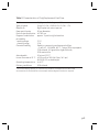
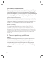
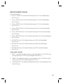
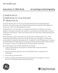
GE Healthcare
Instructions 71-5002-40 AD
Hydrophobic interaction media
TM
Butyl Sepharose 4 Fast Flow
Octyl Sepharose 4 Fast Flow
Butyl Sepharose 4 Fast Flow and Octyl Sepharose 4 Fast Flow form part of the
GE Healthcare media range for hydrophobic interaction chromatography (HIC). They
TM
also belongs to the BioProcess Media family. BioProcess Media are separation media
developed, made and supported for industrial scale, especially the manufacture of
health care products. With their high physical and chemical stability, very high batchto-batch reproducibility, and Regulatory Support File back-up. BioProcess Media are
ideal for all stages of an operation – from process development through scale-up and
into production.
These instructions contain information about media characteristics, column
packing, and maintenance. To ensure best performance and trouble-free operation,
please read these instructions before using Butyl Sepharose 4 Fast Flow and Octyl
Sepharose 4 Fast Flow.
Contents
1. Characteristics
2. Column packing guidelines
3. Evaluation of column packing
3
6
15
4. Media and column maintenance
17
5. Further information
19
6. Ordering information
20
p. 2
1. Characteristics
The base matrix, Sepharose 4 Fast Flow, is a highly cross-linked, 4% agarose
derivative with excellent kinetics, making them ideal for process scale
applications, particularly during initial capture and intermediate stages of a
separation process when high flow rates are required.
The high physical and chemical stabilities of the matrix prevent bed
compression and formation of fines, and allow efficient maintenance
procedures for increased media life time. A typical pressure flow rate curve
is shown below for Butyl Sepharose 4 Fast Flow.
Flow rate (cm/h)
500
400
300
200
0
0.2
0.4
0.6
0.8
1.0
1.2
Pressure (bar)
Fig 1. Typical pressure/flow rate curves for Butyl Sepharose 4 Fast Flow in
an XK 50/30 column, bed height 15 cm; mobile phase 0.1 M NaCl.
p. 3
Table 1. Characteristics of Butyl Sepharose 4 Fast Flow.
Matrix
Type of ligand
Bead form
Mean particle size
Particle size distribution
Degree of substitution
pH stability
working range
cleaning range
Chemical stability
Highly cross linked agarose 4%
Butyl: R-O-CH2 -CH(OH)-CH2 -O-(CH2 ) 3 -CH3
Rigid, spherical, macro porous
90 μm diameter
45–165 μm
approx. 40 μmol butyl/ml medium
3–13
2–14
Stable in commonly used aqueous buffers
– 1 mM HCl, 1 M NaOH, (40 °C, 7 days), 30% isopropanol,
70% ethanol, 6 M guanidine-hydrochloride
Autoclavable
20 min at 121 °C
Linear flow rate at 25 °C ≥ 150 cm/h at 100 kPa (1 bar, 14.5 psi) XK 50/60,
25 cm bed height
Operating temperature 4–40 °C
Delivery conditions
20% ethanol
*The actual loading capacity in a real working situation will depend on the nature and
concentration of contaminants in the sample, and the degree of resolution required.
p. 4
Table 2. Characteristics of Octyl Sepharose 4 Fast Flow.
Matrix
Type of ligand
Bead form
Mean particle size
Particle size distribution
Degree of substitution
pH stability
working range
cleaning range
Chemical stability
Highly cross linked agarose 4%
Octyl: R-O-CH2 -CH(OH)-CH2 -O-(CH2 ) 7 -CH3
Rigid, spherical, macro porous
90 μm diameter
45–165 μm
approx. 5 μmol octyl/ml medium
3–13
2–14
Stable in commonly used aqueous buffers
– 1 mM HCl, 1 M NaOH, (40 °C, 7 days) 30% isopropanol,
70% ethanol, 6 M guanidine-hydrochloride,
30% acetonitrile
Autoclavable
20 min at 121 °C
Linear flow rate at 25 °C ≥ 150 cm/h at 100 kPa (1 bar, 14.5 psi)
XK 50/60, 25 cm bed height
Operating temperature 4–40 °C
Delivery conditions
20% ethanol
*The actual loading capacity in a real working situation will depend on the nature and
concentration of contaminants in the sample, and the degree of resolution required.
p. 5
Method design and optimisation
The main purpose of optimising a chromatographic step is to reach the predefined purity level with highest possible product recovery by choosing the
most suitable combination of the critical chromatographic parameters. In
process chromatography, in contrast to analytical or small scale preparative
chromatography, this has to be accomplished as quickly and economically
as possible, i.e. finding the conditions that give the highest possible
productivity and process economy.
Recommendations for optimising the critical operational parameters which
affect the maximum utilisation of a HIC step can be found in our handbook:
Hydrophobic Interaction Chromatography: Principles and Methods, Code
number 18-1020-90, available from your local GE Healthcare office.
Media screening
To help with screening and selection of media, a HiTrap HIC Test Kit
is available. It consists of 6×1 ml HiTrap columns packed with Phenyl
Sepharose 6 Fast Flow (high sub), Phenyl Sepharose 6 Fast Flow (low sub),
Phenyl Sepharose High Performance, Butyl Sepharose 4 Fast Flow, Butyl-S
Sepharose 6 Fast Flow and Octyl Sepharose 4 Fast Flow, code number
11-0034-53.
2. Column packing guidelines
General
Purifying biological macromolecules by HIC is a typical high selectivity
technique where the difference in retention for the molecules to be
separated can be substantial at any specific ionic strength.
Therefore, relatively short columns can be used if the selectivity of the
adsorbent is exploited in an optimal way. Recommended bed heights
range from 3 to 15 cm, which will minimise back pressure and allow high
throughput.
p. 6
Recommended columns
Lab-scale columns
TM
• Tricorn 5/50 (5 mm i.d.) for bed volumes up to 1.1 ml at bed heights
up to 5.8 cm.
• Tricorn 5/100 (5 mm i.d.) for bed volumes up to 2.1 ml at bed heights
up to 10.8 cm.
• Tricorn 5/150 (5 mm i.d.) for bed volumes up to 3.1 ml at bed heights
up to 15.8 cm.
• Tricorn 10/50 (10 mm i.d.) for bed volumes up to 4.6 ml at bed heights
up to 5.8 cm.
• Tricorn 10/100 (10 mm i.d.) for bed volumes up to 8.5 ml at bed heights
up to 10.8 cm.
• Tricorn 10/150 (10 mm i.d.) for bed volumes up to 12.4 ml at bed heights
up to 15.8 cm.
• XK 16/20 (16 mm i.d.) for bed volumes up to 30 ml at bed heights
up to 15 cm.
• XK 26/20 (26 mm i.d.) for bed volumes up to 80 ml at bed heights
up to 15 cm.
• XK 50/20 (50 mm i.d.) for bed volumes up to 275 ml at bed heights
up to 15 cm.
Large scale columns
TM
•
BPG , variable bed, glass columns: inner diameters from 100–450 mm,
bed volumes up to 130 litres, bed heights max 58 cm.
•
INdEX variable bed columns: inner diameters from 70–200 mm; bed
volumes up to 25 litres, bed heights max 61 cm.
•
CHROMAFLOW variable and fixed bed columns. Inner diameters from
280–2000 mm.
TM
TM
p. 7
Packing process scale columns
General packing procedures
Columns can be packed in different ways depending on the type of
column and equipment used. Always read and follow the relevant column
instruction manual carefully. Sepharose 4 Fast Flow based media are easy
to pack since their rigidity allows the use of high flow rates, see Fig 1.
Three types of packing methods are described:
•
Pressure packing (for columns with adaptors)
•
Hydraulic pressure packing
•
CHROMAFLOW packing
How well the column is packed will have a major effect on the result of
the separation. It is therefore very important to pack and test the column
according to the following recommendations.
Begin the packing procedure by determining the optimal packing flow rate.
Guidelines are given below for determining the optimal packing flow rates
for columns with adaptors and fixed bed heights.
Determining optimal packing flow rates
The optimal packing flow rate is dependent on column size and type,
medium volume, packing solution, and temperature. The optimal packing
flow rate must therefore be determined empirically for each individual
system.
To determine the optimal packing flow rate, proceed as follows:
1. Calculate the amount of medium needed for the slurry (this is especially
important for columns with fixed bed heights). The quantity of medium
required per litre packed volume is approximately 1.15 litres sedimented
medium.
2. Prepare the column exactly as for column packing.
3. Begin packing the medium at a low flow rate (30 cm/h).
4. Increase the pressure in increments and record the flow rate when the
pressure has stabilised. Do not exceed the maximum pressure of the
column, or the maximum flow rate for the medium.
p. 8
5. The maximum flow rate is reached when the pressure/flow curve levels
off or the maximum pressure of the column is reached. Stop the packing
and do not exceed this flow rate. The optimal packing flow rate/pressure
is 70–100% of the maximum flow rate/pressure.
6. Plot the pressure/flow rate curve as in Fig 1 and determine the optimal
packing flow rate.
The operational flow rate/pressure should be <70% of the packing flow
rate/pressure.
Note: For BPSS columns, first pack the column by suction packing at a low
flow rate then determine the flow/pressure characteristics as above
by pumping with downward flow through the column.
Packing methods
Pressure packing
BPG columns
BPG glass columns are supplied with a movable adaptor. They are packed
by conventional pressure packing by pumping the packing solution through
the chromatographic bed at a constant flow rate (or back pressure).
1. Pour some water (or packing solution) into the column. Make sure that
there is no air trapped under the bottom net. Leave about 2 cm of liquid
in the column.
2. Mix the packing buffer with the medium to form a 50–70% slurry.
(Sedimented bed volume/slurry volume = 0.5–0.7). Pour the slurry into
the column. Insert the adaptor and lower it to the surface of the slurry,
making sure no air is trapped under the adaptor. Secure the adaptor in
place.
3. Seal the adaptor O-ring and lower the adaptor a little further into the
slurry to fill the adaptor inlet with packing solution.
4. Connect a pump and a pressure gauge, then start packing at the
predetermined packing flow rate (or pressure). Keep the flow rate (or
pressure) constant during packing and check the pressure at the column
inlet. Never exceed the pressure limit for column or medium.
p. 9
5. When the bed has stabilised, mark the bed height on the column tube,
close the bottom valve and stop the pump. The bed starts rising in the
column. Loosen the O-ring and lower the adaptor to 0.5–1 cm from the
bed surface.
6. Seal the O-ring, start the pump and continue packing. Repeat steps
5 and 6 until there is a maximum of 1 cm between bed surface and
adaptor when the bed has stabilised.
7. Close the bottom valve, stop the pump, disconnect the column inlet and
push the adaptor down to approximately 3 mm below the mark on the
column tube without loosening the adaptor O-ring. The packing solution
will flush the adaptor inlet. Remove any trapped air by pumping liquid
from the bottom (after the inlet tubing and the bottom valve have been
properly filled).
Hydraulic packing
INdEX columns
INdEX columns are supplied with a hydraulic function which allows an
extremely simple, rapid and reproducible packing procedure to be used. The
medium is packed at the same time as the adaptor is lowered into position
at the correct pressure.
The adaptor is pushed down by a constant hydraulic pressure, forcing water
through the slurry and compressing it so that a packed bed is gradually built
up. The hydraulic pressure can be generated using a pump and a pressure
relief valve.
1. Pour some water (or packing solution) into the column. Make sure that
there is no air trapped under the bottom net. Leave about 2 cm of liquid
in the column.
2. Pour the slurry carefully into the column. Fill the column with buffer
solution up to the edge of the glass tube. Mix the slurry and buffer
solution. Allow the medium to settle to below the bevel (G) on the glass
tube, see Fig 2.
3. Rest the adaptor against the bevel (G) on the glass tube. Tilt the lid
slightly to avoid trapping air bubbles under the net when mounting it on
the column. Lower and secure it in place.
p. 10
4. Connect a pump to the inlet of the hydraulic chamber (A) in-line with
a manometer and a pressure relief valve, between the pump and the
hydraulic chamber. The manometer should be placed after the valve in
the direction of the flow.
5. Open the hydraulic inlet (A) and the hydraulic outlet (C). Start the pump
and flush the hydraulic chamber (E) free of air and any residual medium.
6. Close (C) and open the elution inlet/outlet (B) to expel trapped air in the
adaptor net.
7. Close (B) and open the elution inlet/outlet (D) to start packing. Apply a
pre-defined constant hydraulic packing pressure.
8. When the bed has finally settled (no flow at the column outlet), stop the
packing procedure by closing (A) and (D). The adaptor stops moving when
the hydraulic force, acting downwards is equal to the mechanical force of
the bed, expressed upwards.
9. Run the column with upward flow for a few minutes to remove residual air
trapped in the adaptor. The column is now ready for use.
10. To unpack the column, connect the outlet from the pump to (B) and open
(C) while keeping (D) closed. This will cause the adaptor to rise from the
bed surface.
B
C
A
G
E
A.
B.
C.
D.
E.
F.
G.
Hydraulic inlet
Elution inlet/outlet
Hydraulic outlet
Elution inlet/outlet
Hydraulic chamber
Slurry/Packed bed
Bevel on glass tube
F
D
Fig 2. Schematic representation of INdEX column with a 4-port (2-way) valve
mounted at the bottom outlet.
p. 11
Note: The hydraulic pressure used for packing is not comparable to
the back-pressure generated when packing with a pump or
pressure vessel. When using hydraulic pressure packing, the bed is
mechanically compressed during the last part of the procedure. As a
result, the flow properties of the packed bed will be limited by this
mechanical compression.
At any flow rate, the pressure drop over the bed under running conditions is
higher than expected from the hydraulic pressure applied during packing.
It is therefore important to carefully optimize the hydraulic packing pressure
in order to achieve the same flow properties as for columns packed with
conventional techniques using a pump.
When packing Sepharose 4 Fast Flow media in INdEX columns to bed heights
of 15 and 30 cm, the optimal hydraulic packing pressure is between 0.7 bar
and 0.8 bar. The final mechanical compression at the end of the packing
procedure should be about 5 mm. The degree of mechanical compression is
critical for the flow properties of the packed bed.
Packing CHROMAFLOW columns
Procedure
Prepare the column for packing as descriped in the User Manual.
Packing from the top
1. Set the top nozzle to the pack position (mid-position).
2. Fully retract the bottom nozzle (run-position).
3. Ensure that the top mobile phase is closed.
4. Open the bottom mobile phase.
5. Open Inlet C and start the packing pump. Adjust the flow to achieve the
required packing conditions for the selected medium. Monitor column
pressure and the outlet flow rate in order to record column packing
parameters. (Remember to stir the medium slurry during packing to
prevent it from settling.)
6. Continue pumping until the column is fully packed and the pump stalls
due to build-up of medium in its pipelines. Turn off the packing pump.
p. 12
7. Fully retract the top nozzle to its run position. Close Outlet (C). Open Inlet
(B) from the water/buffer tank and open Outlet (D). The pump should
now be restarted to rinse the top slurry lines. (If the nozzle is full of liquid
when in the packing position, make sure that the waste slurry outlet is
open before retracting the nozzle.)
8. To clean-in-place, exchange the buffer tank for wash/buffer tank
containing cleaning solution.
Packing from below
To pack from the bottom, carry out the same procedure for the connections
and flow path via the bottom nozzle. The column is now ready to equilibrate
and test.
Note: It is also possible to use a slightly different packing method
where the amount of medium is packed into the column causing
compression of the bed. When all medium has entered the column
the pump is stopped, the top nozzle is retracted, the bottom mobile
phase valve closed and the medium is allowed to decompress within
the column.
p. 13
SLURRY INLET
Packing position
The top nozzle is extended
part of the way (mid position)
into the column. The bottom
nozzle is fully retracted.
Slurry enters the column via
the top nozzle and excess
liquid exits via the bottom
mobile phase outlet. After
packing, the slurry lines
are isolated from the mobile
phase and can be cleaned
independently from the rest
of the column.
MOBILE PHASE
MOBILE PHASE
Running position
The bottom and top nozzles
are retracted. Mobile phase
enters the column directly
into an annulus, immediately
behind the bed support. The
annulus is cut through at
an angle to ensure that linear
flow rate is kept constant
during distribution of the
mobile phase across the bed.
MOBILE PHASE
BUFFER
WASTE SLURRY
WASTE SLURRY
BUFFER
Unpacking position
In this position, both bottom
and top nozzles are fully
extended into the column,
thereby exposing a third
passage through which
medium leaves the column.
Cleaning solution can be
pumped through the nozzles
and sprayed into the column.
In this way the column is
easily and effectively
cleaned without exposing
the interior or the medium
to the environment, or without
dismantling the column.
Fig 3. Princible of operation – CHROMAFLOW columns
p. 14
3. Evaluation of column packing
To check the quality of the packing and to monitor it during the working life
of the column, column efficiency should be tested directly after packing, at
regular intervals afterwards, and when separation performance is seen to
deteriorate.
The recommended method of expressing the efficiency of a packed column
is in terms of the height equivalent to a theoretical plate, HETP, and the
asymmetry factor, As. These values are easily determined by applying a
sample such as 1% v/v acetone solution to the column. Sodium chloride
can also be used as a test substance. Use a concentration of 2.0 M NaCl in
water with 0.5 M NaCl in water as eluent. Sometimes a concentrated buffer
solution, e.g. 10-fold is preferred.
The calculated plate number will vary depending on the test conditions and
it should therefore be used as a reference value only. It is also important that
conditions and equipment are kept constant so that results are comparable.
Changes in solute, solvent, eluent, sample volume, flow rate, liquid pathway,
temperature, etc. will influence the results.
For optimal results, the sample volume should be at maximum 2.5% of the
column volume and the flow rate between 15 and 30 cm/h.
If an acceptance limit is defined in relation to column performance, the
column plate number can be used as part of the acceptance criteria for
column use.
Method for measuring HETP and A s
To avoid dilution of the sample, apply it as close to the column inlet as
possible.
Conditions
Sample volume:
1.0% of bed volume
Sample conc:
Eluent:
Flow rate:
Detection:
Acetone:
NaCl, buffer:
1.0% (v/v) acetone in water, 2.0 M NaCl or10× buffer
0.5 M NaCl in water, or dilute buffer
30 cm/h
UV 280 nm;
Conductivity
p. 15
Calculate HETP and the number of theoretical plates as follows:
HETP
N
L
N
Ve
Wh
where
= L/N
2
= 5.54(Ve /Wh)
= Bed height (cm)
= number of theoretical plates
= Peak elution distance
= Peak width at half peak height
Ve and Wh are in the same units.
To facilitate comparison of column performance the concept of reduced
plate height is often used.
The reduced plate height is calculated as
HETP/d
where d is the mean diameter of the beads. As a guide, a value of <3 is
normally acceptable.
The peak should be symmetrical, and the asymmetry factor as close as
possible to 1 (values between 0.8–1.5 are usally acceptable). A change in the
shape of the peak is usually the first indication of bed deterioration due to
use.
Peak asymmetry factor calculation:
A s = b/a
where
a = 1st half peak width at 10% of peak height
b = 2nd half peak width at 10% of peak height
As
0.8–1.8 (guide)
Figure 4 shows a UV trace for acetone in a typical test chromatogram in
which the HEPT and A s values are calculated.
p. 16
UV
absorption
Column: BPG 300
Media: Sepharose 6 Fast Flow
Bed height: 57.5 cm
Bed volume: 40.6 litres
Eluent: Distilled water
Sample: 1.05 litres (1% acetone)
Flow rate: 19 cm/h
Ve = 18.7
Wh = 0.9
HETP = 0.024 cm
a: 0.90
b: 0.85
As: 0.94
Wh
a b
Ve
Volume
Fig 4. UV trace for acetone in a typical test chromatogram showing the HETP
and A s values are calculated.
4. Media and column maintenance
Regeneration
For best performance from the media, bound substances must be washed
from the column after each chromatographic cycle.
Wash with 2 bed volumes of water, followed by 2–3 bed volumes of starting
buffer.
To prevent a slow build up of contaminants on the column over time, more
rigorous cleaning protocols may have to be applied on a regular basis.
Cleaning-in-place (CIP)
Cleaning-in-place (CIP) is the removal of very tightly bound, precipitated or
denatured substances from the purification system generated in previous
p. 17
purification cycles. If such contaminants accumulate on the column, they
may affect the chromatographic properties of the column. If the fouling is
severe, it may also block the column, increasing back-pressure and reducing
flow rate.
The following are suggested methods to remove strongly bound
hydrophobic proteins, lipoproteins and lipids:
•
Wash the column with 4–10 bed volumes of up to 70% ethanol or 30%
isopropanol followed by 3–4 bed volumes of water. Apply gradients to
avoid air bubble formation when using high concentrations of organic
solvents.
•
Alternatively, wash the column with 1–2 bed volumes of 0.5% non-ionic
detergent (e.g. in 1 M acetic acid), followed by 5 bed volumes of
70% ethanol to remove the detergent, and 3–4 bed volumes of water.
Caution: Specific regulations may apply when using 70% ethanol since it
can require the use of explosion-proof areas and equipment. Consult your
local safety regulations for more information.
To remove other contaminants the following method is suggested:
•
Wash the column with 4 bed volumes of 0.5–1.0 M NaOH at 40 cm/h,
followed by 2–3 bed volumes of water.
The CIP protocols given above should be used as guidelines when
formulating a cleaning protocol specific for the raw material used. The
frequency of CIP will depend on the raw material applied to the column,
but it is recommended to use a CIP procedure at least every 5 cycles
during normal use. Depending on the nature of the contaminants, different
protocols may have to be used in combination. If fouling is severe, the
protocols may have to be further optimised. During CIP flow direction
through the column should be reversed.
Sanitisation
Sanitisation is the reduction microbial contamination in the column and
related equipment to an acceptable minimum. A specific sanitisation
protocol should be designed for each process according to the type of
contaminants present. The following is a recommended protocol.
p. 18
Wash the column with 0.5–1.0 M NaOH at a flow rate of approximately
40 cm/h, contact time 30–60 minutes.
Sterilisation
To sterilise Butyl Sepharose 4 Fast Flow or Octyl Sepharose 4 Fast Flow,
dismantle the column and autoclave the medium for 20 minutes at 120 °C.
Storage
Store Butyl Sepharose 4 Fast Flow and Octyl Sepharose 4 Fast Flow in
20% ethanol, at +4 to +30 °C, to avoid microbiological growth.
5. Further information
Please read these instructions carefully before using Butyl Sepharose 4 Fast
Flow or Octyl Sepharose 4 Fast Flow Medium.
For further information visit www.amershambiosciences.com or contact
your local GE Healthcare representive.
p. 19
6. Ordering information
Product
Pack size
Code No
Butyl Sepharose 4 Fast Flow
25 ml
200 ml
500 ml
5 litres
17-0980-10
17-0980-01
17-0980-02
17-0980-04
Octyl Sepharose 4 Fast Flow
25 ml
200 ml
1 litre
5 litres
17-0946-10
17-0946-02
17-0946-03
17-0946-04
HiTrap HIC Test Kit
HiTrap Butyl FF
HiTrap Butyl FF
HiTrap Octyl FF
HiTrap Octyl FF
HiPrep 16/10 Butyl FF
HiPrep 16/10 Octyl FF
Tricorn 5/50
Tricorn 5/100
Tricorn 5/150
Tricorn 10/50
Tricorn 10/100
Tricorn 10/150
XK 16/20
XK 26/20
6 × 1 ml
5 × 1 ml
5 × 5 ml
5 × 1 ml
5 × 5 ml
20 ml
20 ml
1
1
1
1
1
1
1
1
11-0034-53
17-1357-01
17-5197-01
17-1359-01
17-5196-01
17-5096-01
17-5097-01
18-1163-09
18-1163-10
18-1163-11
18-1163-14
18-1163-15
18-1163-16
18-8773-01
18-1000-72
Handbook
Hydrophobic Interaction Chromatography and Reversed Phase Chromatography:
Principles and Methods
11-0012-69
The complete range of Sepharose Fast Flow media includes other HIC media
as well as media for ion exchange and affinity chromatography. Further
information is available upon request.
p. 20
Columns
For information about process scale columns, please ask for the following
Data Files.
Data File
Code No
BPG 100, 140, 200, 300, 450
INdEX
CHROMAFLOW
18-1115-23
18-1115-61
18-1138-92
p. 21
p. 22
p. 23
www.gehealthcare.com
GE Healthcare Bio-Sciences AB
Björkgatan 30
751 84 Uppsala
Sweden
GE Healthcare Europe GmbH
Munzinger Strasse 5
D-79111 Freiburg
Germany
GE Healthcare UK Ltd
Amersham Place
Little Chalfont
Buckinghamshire, HP7 9NA
UK
GE Healthcare Bio-Sciences Corp
800 Centennial Avenue
P.O. Box 1327
Piscataway, NJ 08855-1327
USA
GE Healthcare Bio-Sciences KK
Sanken Bldg.
3-25-1, Hyakunincho
Shinjuku-ku, Tokyo 169-0073
Japan
All goods and services are sold subject to the terms and conditions of sale of the company within GE Healthcare which
supplies them. GE Healthcare reserves the right, subject to any regulatory and contractual approval, if required, to make
changes in specifications and features shown herein, or discontinue the product described at any time without notice or
obligation. Contact your local GE Healthcare representative for the most current information.
© 2006 General Electric Company – All rights reserved.
GE Healthcare Bio-Sciences AB, a General Electric Company.
71-5002-40 AD 04/2006
Elanders Östervåla 2006
BioProcess, BPG, CHROMAFLOW, Drop Design, HiPrep, HiTrap, INdEX, Sepharose and Tricorn are trademarks of
GE Healthcare companies. GE, imagination at work and GE monogram are trademarks of General Electric Company.