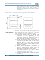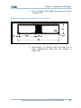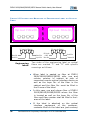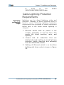
1
ZXR10 2609/2818S/2826S/2852S Access Switch Handy User Manual Version 1.0 ZTE CORPORATION ZTE Plaza, Keji Road South, Hi-Tech Industrial Park, Nanshan District, Shenzhen, P. R. China 518057 Tel: (86) 755 26771900 800-9830-9830 Fax: (86) 755 26772236 URL: http://support.zte.com.cn E-mail: [email protected] LEGAL INFORMATION Copyright © 2006 ZTE CORPORATION. The contents of this document are protected by copyright laws and international treaties. Any reproduction or distribution of this document or any portion of this document, in any form by any means, without the prior written consent of ZTE CORPORATION is prohibited. Additionally, the contents of this document are protected by contractual confidentiality obligations. All company, brand and product names are trade or service marks, or registered trade or service marks, of ZTE CORPORATION or of their respective owners. This document is provided “as is”, and all express, implied, or statutory warranties, representations or conditions are disclaimed, including without limitation any implied warranty of merchantability, fitness for a particular purpose, title or noninfringement. ZTE CORPORATION and its licensors shall not be liable for damages resulting from the use of or reliance on the information contained herein. ZTE CORPORATION or its licensors may have current or pending intellectual property rights or applications covering the subject matter of this document. Except as expressly provided in any written license between ZTE CORPORATION and its licensee, the user of this document shall not acquire any license to the subject matter herein. The contents of this document and all policies of ZTE CORPORATION, including without limitation policies related to support or training are subject to change without notice. Revision History Date Revision No. Serial No. Reason for Revision 28/9/2006 R1.0 Sjzl20061549 First edition ZTE CORPORATION Values Your Comments & Suggestions! Your opinion is of great value and will help us improve the quality of our product documentation and offer better services to our customers. Please fax to: (86) 755-26772236; or mail to Documentation R&D Department, ZTE CORPORATION, ZTE Plaza, A Wing, Keji Road South, HiTech Industrial Park, Shenzhen, P. R. China 518057. Thank you for your cooperation! Your Comments & Suggestions Document Name ZXR10 2609/2818S/2826S/2852S Access Switch Handy User Manual Product Version V1.0 Document Revision Number R1.0 Equipment Installation Date Presentation: (Introductions, Procedures, Illustrations, Completeness, Level of Detail, Organization, Appearance) Good Your evaluation of this document Fair Average Poor Bad N/A Accessibility: (Contents, Index, Headings, Numbering, Glossary) Good Fair Average Poor Bad N/A Intelligibility: (Language, Vocabulary, Readability & Clarity, Technical Accuracy, Content) Good Fair Average Poor Bad N/A Please check the suggestions which you feel can improve this documentation: Your suggestions for improvement of this document Improve the overview/introduction Make it more concise/brief Improve the Contents Add more step-by-step procedures Improve the organization Add more troubleshooting information Include more figures Make it less technical Add more examples Add more/better quick reference aids Add more detail Improve the index Other suggestions ____________________________________________________________________ ____________________________________________________________________ ____________________________________________________________________ ____________________________________________________________________ ____________________________________________________________________ # Please feel free to write any comments on an attached sheet. If you wish to be contacted regarding your comments, please complete the following: Name Company Postcode Address Telephone E-mail Contents About this Manual................................................................... i Purpose.............................................................................................i Intended Audience .............................................................................i Prerequisite Skill and Knowledge .........................................................i What is in This Manual........................................................................i Conventions .....................................................................................ii How to Get in Touch......................................................................... iii Chapter 1................................................................................ 1 System Overview................................................................... 1 Networking Mode .................................................................. 3 Workgroup Networking Mode............................................................ 3 MAN Broadband Access Networking Mode.......................................... 4 Technical Features and Parameters ................................................... 5 Chapter 2................................................................................ 7 Hardware Structure............................................................... 7 Overview......................................................................................... 7 Switch Architecture .......................................................................... 8 Hardware Description............................................................ 9 ZXR10 2609 ...................................................................................10 ZXR10 2818S .................................................................................11 ZXR10 2826S .................................................................................13 ZXR10 2852S .................................................................................14 Sub-boards ....................................................................................16 FFEI...............................................................................................16 FGEI ..............................................................................................18 FGFI ..............................................................................................18 FGFE..............................................................................................19 Power Supply Module.......................................................... 20 ZXR10 2609...................................................................................20 ZXR10 2818S/2826S ......................................................................20 ZXR10 2852S.................................................................................21 Chapter 3 ............................................................................. 23 Installation and Debugging ................................................ 23 Overview........................................................................................23 Installing Switch on Desktop ............................................................23 Installing Switch onto Cabinet ..........................................................24 Installing of Cables..........................................................................28 Installing Power Cables....................................................................28 Installing Configuration Cables .........................................................30 Installing Network Cables ................................................................31 Installing Fibers ..............................................................................33 Labels............................................................................................34 Cable Lightning Protection Requirements ..........................................39 System Debugging .............................................................. 42 Connection Configuration.................................................................42 Power-on Procedure........................................................................45 Indicator Status ..............................................................................47 Default username and password ......................................................48 Chapter 4 ............................................................................. 49 Maintenance.........................................................................49 Routine Maintenance.......................................................................49 Daily Maintenance Items .................................................................49 Monthly Maintenance Items .............................................................50 Maintenance Period.........................................................................51 This page is intentionally blank. About this Manual Purpose This Manual provides procedures and guidelines to ZXR10 2609/2818S/2826S/2852S. Intended Audience This document is intended for engineers and technicians who have knowledge and command on layer 2 switches. Prerequisite Skill and Knowledge To use this document effectively, users should have a general understanding of layer 2 switches. Familiarity with the following is helpful: Networking mode Hardware installation of switches Installation of cables. What is in This Manual This Manual contains the following chapters: Confidential and Proprietary Information of ZTE CORPORATION i ZXR10 2609/2818S/2826S/2852S Access Switch handy User Manual TABLE 1 CHAPTER SUMM ARY Chapter Summary Chapter 1 Introduces networking mode technical features and parameters. Chapter 2 Overview of hardware structure and description. Chapter 3 Installation and debugging of cables. Chapter 4 Maintenance procedures on daily, monthly and yearly. Conventions Typographical Conventions ZTE documents employ typographical conventions. the following TABLE 2 TYPOGRAPHICAL CONVENTIONS Typeface Meaning Italics References to other Manuals and documents. “Quotes” Links on screens. Bold Menus, menu options, function names, input fields, radio button names, check boxes, drop-down lists, dialog box names, window names. CAPS Keys on the keyboard and buttons on screens and company name. Constant width Text that you type, program code, files and directory names, and function names. [] Optional parameters. {} Mandatory parameters. | Select one of the parameters that are delimited by it. Note: Provides additional information about a certain topic. ii Confidential and Proprietary Information of ZTE CORPORATION About this Manual Typeface Meaning Checkpoint: Indicates that a particular step needs to be checked before proceeding further. Tip: Indicates a suggestion or hint to make things easier or more productive for the reader. Mouse Operation Conventions TABLE 3 MOUSE OPERATION CONVENTIONS Typeface Meaning Click Refers to clicking the primary mouse button (usually the left mouse button) once. Double-click Refers to quickly clicking the primary mouse button (usually the left mouse button) twice. Right-click Refers to clicking the secondary mouse button (usually the right mouse button) once. Drag Refers to pressing and holding a mouse button and moving the mouse. How to Get in Touch The following sections provide information on how to obtain support for the documentation and the software. Customer Support Documentation Support If you have problems, questions, comments, or suggestions regarding your product, contact us by e-mail at [email protected]. You can also call our customer support center at (86) 755 26771900 and (86) 800-9830-9830. ZTE welcomes your comments and suggestions on the quality and usefulness of this document. For further questions, comments, or suggestions on the documentation, you can contact us by email at [email protected]; or you can fax your comments and suggestions to (86) 755 26772236. You can also browse our website at Confidential and Proprietary Information of ZTE CORPORATION iii ZXR10 2609/2818S/2826S/2852S Access Switch handy User Manual http://support.zte.com.cn, which contains various interesting subjects like documentation, knowledge base, forum and service request. iv Confidential and Proprietary Information of ZTE CORPORATION Chapter 1 System Overview Introduction Functions ZXR10 2609/2818S/2826S/2852S access switches are located at access layer of enterprise network and broadband IP metropolitan area network (MAN), providing different number of Ethernet ports. They can serve as the access equipment at the subscriber side in the information intelligent residential areas, commercial buildings, hotels, campus networks, enterprise (government) network or the convergence equipment of small-size network to provide fast, efficient, and cost-effective access and convergence solutions. ZXR10 2609/2818S/2826S/2852S adopts the Store and Forward mode and supports the layer2 switching at wire-speed. Full wire-speed switching is implemented at all ports. The ZXR10 2609/2818S/2826S/2852S following functions: has MAC address is self-learning capability. The size of the MAC address table is 8K (8*1024). Confidential and Proprietary Information of ZTE CORPORATION 1 ZXR10 2609/2818S/2826S/2852S Access Switch handy User Manual 2 Supports 802.1q-compliant VLAN and private VLAN. Maximum number of VLANs can be up to 4094. VLAN stacking function is also supported. Priority classification by DA, SA, VID, or TOS/DSCP, multi-queue, fixed priority scheduling, weighted priority scheduling, and port multi-queue at the switch. Supports STP defined in the 802.1d, RSTP defined in the 802.1w, and MSTP defined in the 802.1s. Support LACP port bundling defined in 802.3ad and port static bundling. Maximum 16 port groups can be bundled. Each group contains eight ports. Multi-VLAN IGMP snooping. Port ingress and egress mirroring. 802.3x-compliant flow control (full duplex) and back-pressure flow control (half duplex). Port ingress and egress bandwidth restriction. Single port loop test. Virtual Cable Tester (VC function and faulty circuit test. Description of port statistics. Broadcast storm suppression. Configuration of NM static route. 802.1x transparent authentication. Supports Console configuration, Telnet remote login, Web-Management configuration, SNMP network management, centralized network management of ZXNM01, trunking management technology ZGMP, and Secure shell V2.0. Uploading and downloading of TFTP files. transmission Confidential and Proprietary Information of ZTE CORPORATION and Chapter 1 System Overview Networking Mode ZXR10 2609/2818S/2826S/2852S has following networking modes: Workgroup networking mode MAN broadband access networking mode Workgroup Networking Mode ZXR10 2609/2818S/2826S/2852S is employed in workgroup-level networks like enterprise and department networks. ZXR10 2609/2818S/2826S/2852S provides 8 to 48 10/100M interfaces. Number of interfaces can be extended through cascading of switches. Extension slot can provide100M or 1000M highspeed optical interfaces to connect with backbone network or high-speed server. Networking structure is shown in Figure 1. Confidential and Proprietary Information of ZTE CORPORATION 3 ZXR10 2609/2818S/2826S/2852S Access Switch handy User Manual FIGURE 1 TYPICAL WORKGROUP NETWORKING STRUCTURE IP backbone network 100M/1000M ZXR10 2609/2818S/2826S/2852S Server 10/100M 10/100M 10/100M ZXR10 2609/2818S/2826S/2852S 10/100M 10/100M 10/100M 10/100M 10/100M MAN Broadband Access Networking Mode In construction of broadband MAN, ZXR10 2609/2818S/2826S/2852S can be equipped at access layer of residential blocks or convergence layer of buildings. It can directly provide 10/100M access of subscribers. It connects to switch at access layer for example ZXR10 1816. With flexible uplink port of ZXR10 2609/2818S/2826S/2852S, 100M/1000M optical interface can be configured to connect to convergence node of residential blocks. It builds a broadband service network for an information residential block along with network management systems such as Broadband Access 4 Confidential and Proprietary Information of ZTE CORPORATION Chapter 1 System Overview Server (BRAS), and (authentication, authorization and accounting) AAA server. Customer Premises Network equipment can be included via in-band or out-band mode into the NMS of the entire MAN. It can also be managed with the network management and service management system established in the residential complex. Networking structure can be seen in Figure 2. F I G U R E 2 T Y P I C A L N E T W O R K I N G O F M AN B R O A D B A N D A C C E S S AAA server IP backbone network BRAS Email/DNS/ DHCP server 100M/1000M ZXR10 3906 N×10/100M 100M ZXR10 2609 100M Network/Property management server ZXR10 2826S ZXR10 2818S 10/100M 1000M 10/100M ZXR10 2852S/2826S Technical Features and Parameters The ZXR10 2609/2818S/2826S/2852S complies with following standard: Confidential and Proprietary Information of ZTE CORPORATION 5 ZXR10 2609/2818S/2826S/2852S Access Switch handy User Manual Q/SZX 193-2005 ZXR10 2609/2818S/2826S/2852S Access Switch Table 4 lists technical features and parameters of ZXR10 2609/2818S/2826S/2852S. TABLE 4 TECHNIC AL FE ATURE AND P ARAMETERS Model ZXR10 2609 Item Dimensions (HxWxD, mm) ZXR10 2818S ZXR10 2826S ZXR10 2852S 35× 21× 130 43.6× 436× 200 43.6× 436× 200 43.6 × 442 × 280 ≈1 ≈2 ≈2 ≈2.5 7 9 14 19 Weight (Fully equipped, kg) Maximum power consumption (W) Power supply AC power supply: 100V~240V, 48Hz~62Hz. Wave shape distortion <5% DC power supply: –57V to –40V 6 Confidential and Proprietary Information of ZTE CORPORATION Chapter 2 Hardware Structure Overview Introduction This chapter provides an overview of technical and hardware structural information on each of the ZXR10 2609/2818S/2826S/2852S. Features ZXR10 2609/2818S/2826S/2852S are layer-2 medium and low range Ethernet switching products developed by ZTE Corporation. They are useful for variety of communication applications. These switches are at the access layer of the networks in hotel industry, multinational companies, residential areas and universities. These switches provide excellent performance for individual users by allocating dedicated bandwidth to each switch port. They are frequently installed in the enterprise for high-speed connectivity between end stations of the data link layer. Confidential and Proprietary Information of ZTE CORPORATION 7 ZXR10 2609/2818S/2826S/2852S Access Switch handy User Manual Switch Architecture Switches consist of following modules: Control module Switching module Interface module Power supply module Control Module It has main processor and external chips. The control module manages the switching module to meet the requirements of different network applications. It provides an external serial port for the data operation and maintenance. Switching Module Switching module has Ethernet switching processing chips. Its primary function is simply switching traffic from multiple devices. This chip is interlinked with data packet transceiver. It can provide hundred megabit and gigabit service for users. Interface Module Interface module is in ZXR10 2818S and 2826S only. It has interface board. Interface module connects external users and transferring of data packets. Standard interface module connects the interface and switching module. Power Supply Module Power supply is of 22V AC or –48V DC. The power supply module supplies power to other modules of the system. 8 Confidential and Proprietary Information of ZTE CORPORATION Chapter 2 Hardware Structure FIGURE 3 ZXR10 2609/2818S/2826S/2852S Interface module (hundred megabit or gigabit interface) Switching module Power module Hundred megabit or gigabit service interface of the customer Control module Important! ZXR10 2609/2818S/2826S/2852S (except the ZXR10 2609) are placed in 19U sub rack. Hardware Description ZXR10 2609/2818S/2826S/2852S have box structures and are 1U high. These switches employ independent power supply. External structure of switches These switches have vents on the right and left side of the boxes. This box has a bottom case and shell. It is lightweight and simple structure. All components are installed on bottom case that results in easy installation and uninstallation. Confidential and Proprietary Information of ZTE CORPORATION 9 ZXR10 2609/2818S/2826S/2852S Access Switch handy User Manual Front panel of switches On front panel of ZXR10 2609/2818S/2826S/2852S are power indicators, Run indicators, fixed Ethernet electrical interfaces, Ethernet optical interfaces and one serial configuration port. Main board of switches Interface board is inserted from front side and is fixed with two captive screws. On the rear, panel AC or DC power socket and power switches are located. Hardware of the ZXR10 2609/2818S/2826S/2852S is Ethernet switching main board. It is vital for any type of configuration. Uplink port on expansion slot of ZXR10 2818S and 2826S can be configured with different sub-boards as per requirement. ZXR10 2609 Front panel of ZXR10 2609 Figure 4 shows front panel of the ZXR10 2609. FIGURE 4 FRONT P ANEL OF THE ZXR10 2609 Ethernet switching main board of ZXR10 2609 is FEBN. Interfaces of ZXR10 2609 ZXR10 2609 provides the following types of access ports: 10 Nine fixed 10/100 Base-T Ethernet ports. These ports support full/half duplex, Confidential and Proprietary Information of ZTE CORPORATION Chapter 2 Hardware Structure 10/100M function. Indicators of ZXR10 2609 and MDI/MDIX auto-sensing One Console port is to realize the management and configuration of different services. There are 11 indicators on the top of the shell of the ZXR10 2609 including two system indicators and remaining nine interface indicators. System indicators include power indicator (PWR) and running indicator (RUN). f After the system is powered up, the PWR indicator is on and the RUN indicator is off. f Boot-Rom starts to load the version. If the version is unavailable then the status of indicators does not change. If the version is loaded normally, the RUN indicator flashes at 1Hz. Nine interface indicators correspond to the nine fixed Ethernet electrical interfaces. When the indicator is on, it indicates that the LINK is normal. If the indicator is flashing, it indicates that data sending or receiving is in progress. ZXR10 2818S Front panel of ZXR10 2818S Figure 5 shows front panel of the ZXR10 2818S. FIGURE 5 FRONT P ANEL OF ZXR10 2818S Confidential and Proprietary Information of ZTE CORPORATION 11 ZXR10 2609/2818S/2826S/2852S Access Switch handy User Manual Ethernet switching main board of the ZXR10 2818S is FEBE. The ZXR10 2818S can also be configured with the following sub-boards: FFEI, FGEI, FGFI and FGFE. For the description of the sub-boards, see Sub-boards. Interfaces of ZXR10 2818S Indicators of ZXR10 2818S ZXR10 2818S provides the following types of access ports. Sixteen fixed 10/100 Base-T Ethernet ports. These ports support full/half duplex, 10/100M, MDI/MDIX auto-sensing function and VCT auto detection function. There is one expansion slot for the uplink sub-boards that can provide single/doublechannel 100M optical interfaces, 2-channel 1000M optical interface, 2-channel 1000M electrical interface or 1000M opticalelectrical interface. One Console port is to realize the management and configuration of various services. On the top of the shell and front panel of the ZXR10 2818S, there are 18 indicators that include two system indicators and 16 interface indicators. 12 System indicators include power indicator (PWR) and running indicator (RUN). f After the system is powered up, the PWR indicator is on and the RUN indicator is off. f Boot-Rom starts to load the version. If the version is unavailable, the status of indicators does not change. If the version is loaded normally then the RUN indicator flashes at 1Hz. Confidential and Proprietary Information of ZTE CORPORATION Chapter 2 Hardware Structure 16 interface indicators correspond to the 16 fixed Ethernet electrical interfaces. When the indicator is on it will indicate that the Link is normal. If the indicator is flashing, it indicates that data sending or receiving is in progress. ZXR10 2826S Front panel of ZXR10 2826S Figure 6 shows front panel of ZXR10 2826S. FIGURE 6 FRONT P ANEL OF ZXR10 2826S Ethernet switching main board of the ZXR10 2826S is FEBE. The ZXR10 2818S can also be configured with the following sub-boards: FFEI, FGEI, FGFI and FGFE. For the description of the sub-boards, refer to Sub-boards. Interfaces of ZXR10 2826S ZXR10 2826S provides the following types of access ports. Twenty-four fixed 10/100 Base-T Ethernet ports. These ports support full/half duplex, 10/100M and MDI/MDIX auto-sensing function. These ports also support VCT auto detection function. One expansion slot for the uplink sub-boards can provide single/double-channel 100M optical interface, 2-channel 1000M optical interface, 2-channel 1000M electrical interface or 1000M optical-electrical interface. Confidential and Proprietary Information of ZTE CORPORATION 13 ZXR10 2609/2818S/2826S/2852S Access Switch handy User Manual Indicators of ZXR10 2826S One Console port is to realize the management and configuration of different services. On the front panel of the ZXR10 2826S, there are 50 indicators, including two system indicators and 48 interface indicators. System indicators include power indicator (PWR) and operation indicator (RUN). f After the system is powered on, the PWR indicator is on and the RUN indicator is off. f Boot-Rom starts to load the version. If the version is unavailable, the indicator states do not change. If the version is loaded normally, the RUN indicator flashes at 1Hz. There are two indicators on each fixed Ethernet electrical port. The left one is the full/half duplex indicator and the right one is the link activation indicator. f The full/half duplex indicator is on then the Ethernet electrical port that works in full duplex mode. When it is off then the Ethernet electrical port works in half duplex mode and flashes when there is conflict. f Link activation indicator flashes when the link is activated. ZXR10 2852S Front panel of ZXR10 2852S 14 Figure 7 shows front panel of the ZXR10 2852S. Confidential and Proprietary Information of ZTE CORPORATION Chapter 2 Hardware Structure FIGURE 7 FRONT P ANEL OF ZXR10 2852S Ethernet switching main board of the ZXR10 2852S is FEBF. Interfaces of ZXR10 2852S Indicators of ZXR10 2852S ZXR10 2852S provides the following types of access ports. Forty-eight fixed 10/100 Base-T Ethernet ports. These ports support full/half duplex, 10/100M, MDI/MDIX auto-sensing function and VCT auto detection function. Two fixed 10/100/1000 Ethernet electrical ports and two fixed 1000 Ethernet electrical ports. One Console port is for the purpose of management and configuration of services. On the front panel of the ZXR10 2852S, there are 56 indicators, including four system indicators and 52 interface indicators. System indicator includes two Console port indicators: power indicator (PWR) and running indicator (RUN) explained below: f After the system is powered up, the PWR indicator is on and the RUN indicator is off. f Boot-Rom starts to load the version. If the version is unavailable then the states of indicators do not change. If the version is loaded normally, the RUN indicator flashes at 1Hz. Confidential and Proprietary Information of ZTE CORPORATION 15 ZXR10 2609/2818S/2826S/2852S Access Switch handy User Manual Interface indicators include The 48 indicators on the upper part of the front panel correspond to 48 fixed Ethernet electrical ports. When the indicator is on, it indicates that the Link is normal. If the indicator is flashing, it indicates that data sending or receiving is active. The ACT1 and ACT2 on the left correspond to two fixed gigabit optical interfaces. When the indicator is on then it indicates that the Link is normal. If the indicator is flashing, it indicates that data sending or receiving is in process. Fixed gigabit Ethernet port has two indicators on each side. Left half/full duplex indicator is on when the Ethernet electrical port works in the full duplex mode. When it is off then the Ethernet electrical port works in the half duplex mode and flashes when there is conflict. The right link activation indicator flashes when the link is activated. Sub-boards Introduction to Sub-boards ZXR10 2816S and ZXR10 2826S can be configured with following sub-boards: FFEI, FGEI, FGFI, and FGFE. FFEI FFEI sub-board models FFEI provides one channel of 100M Ethernet uplink optical interfaces for ZXR10 2818S/2826S. There are three FFEI models providing different types of interface and transmission distance: 1. SF-1FE-S40KSC 2. SF-1FE-S15KSC 3. SF-1FES40KSC model 16 SF-1FE-M02KS Extended distance to 40 km over single-mode fiber cable. Figure 8 shows this sub-board. Confidential and Proprietary Information of ZTE CORPORATION Chapter 2 Hardware Structure FIGURE 8 SF-1FE-S40KSC SUB-BOARD SF-1FES15KSC model Extend distance to 15 km over single-mode fiber cable. Figure 9 shows this sub-board. FIGURE 9 SF-1FE-S15KSC SUB-BOARD SF-1FEM02KS C model SF-1FE-M02KSC Extend distance to 2 km over dual-mode fiber cable. Figure 10 shows this sub-board. FIGURE 10 SF-1FE-M02KSC SUB-BOARD On front panel of FFEI, there are two indicators: The ACT indicator flashes when data sending or receiving is underway. Confidential and Proprietary Information of ZTE CORPORATION 17 ZXR10 2609/2818S/2826S/2852S Access Switch handy User Manual The LNK indicator is on when the link is normal. FGEI FGEI sub-board model FGEI provides two channels of gigabit Ethernet uplink electrical ports for the ZXR10 2818S/2826S. Its model number is SF-2GE2RJ45, as shown in Figure 11. FIGURE 11 SF-2GE-2RJ45 SUB-BOARD (FGEI) On the panel of the FGEI, there are four indicators. Each gigabit electrical port has two indicators: FGEI sub-board indictors Link activation indicator flashes when data sending or receiving is underway. Link status indicator is on when the link is normal. FGFI FGFI sub-board model 18 FGFI provides two channels of gigabit Ethernet uplink optical ports for the ZXR10 2818S/2826S. Its model number is SF-2GE2SFP, as shown in Figure 12. Confidential and Proprietary Information of ZTE CORPORATION Chapter 2 Hardware Structure FIGURE 12 SF-2GE-2SFP SUB-BOARD (FGFI) FGFI sub-board indicators On panel of FGFI, there are two indicators: ACT1 and ACT2. They correspond to two-gigabit optical interfaces. When indicator is on, it indicates that Link is normal. If indicator is flashing, it indicates that data sending or receiving is in progress. FGFE FGFE sub-board model FGFE provides one channel of gigabit Ethernet uplink electrical port and another of gigabit Ethernet uplink optical port for the ZXR10 2818S/2826S. Its model number is SF-2GESFPRJ45, as shown in Figure 13 FIGURE 13 SF-2GE-SFPRJ45 SUB-BOARD (FGFE) FGFE sub-board indicators On the panel of the FGFE, there are three indicators. The gigabit optical port has an ACT indicator. When the indicator is on, it indicates that the Link is normal. If the indicator is flashing, it indicates that data sending or receiving is underway. There are two types of Giga byte indicators: Confidential and Proprietary Information of ZTE CORPORATION 19 ZXR10 2609/2818S/2826S/2852S Access Switch handy User Manual Link activation indicator flashes when data sending or receiving is underway. Link status indicator is on when the link is normal. Power Supply Module ZXR10 2609 ZXR10 2609 supports two power supply modes: 110/220V AC power supply and POE powered mode. When the AC power supply is used then the self-contained AC adapter can be directly used to convert the AC power into 5V DC power. When the POE powered mode is used then a dedicated POE device is needed to split the RJ45 signals of the 48V power provided by the POE power sourcing equipment into Ethernet signal and 48V power signal and convert the power into 5V DC power needed by the ZXR10 2609. ZXR10 2818S/2826S ZXR10 2818S/2826S supports two power supply modes: -48V DC power supply and 110/220V AC power supply. 20 When the -48V DC power supply is switched on then the 48V DC power cables are to be used. When the AC power supply is adopted then AC power cables are to be used. Confidential and Proprietary Information of ZTE CORPORATION Chapter 2 Hardware Structure ZXR10 2818S also supports the POE power mode but the powered device must be Ethernet port. ZXR10 2852S ZXR10 2852S supports two power supply modes: -48V DC power supply and 110/220V AC power supply. When the -48V DC power supply is used then the 48V DC power cables are used. When the AC power supply is in use then the AC power cables are used. Confidential and Proprietary Information of ZTE CORPORATION 21 ZXR10 2609/2818S/2826S/2852S Access Switch handy User Manual This page is intentionally blank. 22 Confidential and Proprietary Information of ZTE CORPORATION Chapter 3 Installation and Debugging Overview This chapter provides an overview of installation of ZXR10 2609/2818S/2826S2852S on desktop, cabinet and installing of cables. Equipment Installation ZXR10 2609/2818S/2826S/2852S is installed on desktop and on 19” standard cabinet (except the ZXR10 2609). The 19” standard cabinet can be provided by customer. If ZTE provides the cabinet, install cabinet as per 19” Standard Cabinet Installation Manual. Installing Switch on Desktop When switch is placed on desktop, install four plastic feet (plastic feet and screws are delivered with switch) on bottom plate of switch. Four feet Confidential and Proprietary Information of ZTE CORPORATION 23 ZXR10 2609/2818S/2826S/2852S Access Switch handy User Manual supports switch and is for air exhaust vent for the dissipation of the power supply module. Installing Switch onto Cabinet To install the switch onto a 19” cabinet, two flanges should be installed on both sides of the box of the switch (the flanges and screws come with the equipment), as shown in Figure 14. 24 Confidential and Proprietary Information of ZTE CORPORATION Chapter 3 Installation and Debugging FIGURE 14 INSTALLING FL ANGES ZXR10 2818S 2 4 6 8 10 12 14 16 1 3 5 7 9 11 13 15 SF-2GE-2RJ45 LNK/ACT ESD 2 4 6 8 10 12 14 16 1 3 5 7 RUN PWR Console 9 11 13 15 2 4 6 8 10 12 14 16 18 20 22 24 1 3 5 7 9 11 13 15 17 19 21 23 ZXR10 2826S ESD SF-2GE-2RJ45 RUN PWR Console ZXR10 2852S TX CONSOLE RX TX 52 RX 51 50/49 2/1 4/3 6/5 8/7 10/9 12/11 14/13 16/15 18/17 20/19 22/21 24/23 26/25 28/27 30/29 32/31 34/33 36/35 38/37 40/39 42/41 44/43 46/45 48/47 1 Box 2 Flange 3 Screw Confidential and Proprietary Information of ZTE CORPORATION 25 ZXR10 2609/2818S/2826S/2852S Access Switch handy User Manual On both sides of 19” cabinet, install two symmetric holders for support of switch, as shown in Figure 15. FIGURE 15 INST ALLING HOLDERS 2 1 3 26 1 Holder 2 Cabinet 3 Screw Confidential and Proprietary Information of ZTE CORPORATION Chapter 3 Installation and Debugging After holders are installed, push the switch along with holders and fix the flanges onto cabinet, as shown in Figure 16. FIGURE 16 FIXING EQUIPMENT ZXR10 2818S 2 4 6 8 10 12 14 16 1 3 5 7 9 11 13 15 SF-2GE-2RJ45 LNK/ACT ESD 2 4 6 8 10 12 14 16 1 3 5 7 RUN PWR 9 11 13 15 Console 2 4 6 8 10 12 14 16 18 20 22 24 1 3 5 7 9 11 13 15 17 19 21 23 ZXR10 2826S ESD SF-2GE-2RJ45 RUN PWR Console ZXR10 2852S RX TX TX CONSOLE 52 RX 51 50/49 2/1 4/3 6/5 8/7 10/9 12/11 14/13 16/15 18/17 20/19 22/21 24/23 26/25 28/27 30/29 32/31 34/33 36/35 38/37 40/39 42/41 44/43 46/45 48/47 1 Cabinet 2 Box 3 Screw Confidential and Proprietary Information of ZTE CORPORATION 27 ZXR10 2609/2818S/2826S/2852S Access Switch handy User Manual Installing of Cables Cables of include: ZXR10 2609/2818S/2826S/2852S Power cables Configuration cables Network cables Fibers Installing Power Cables Power cables are classified as per power supply module: Install AC power cables AC power cables DC power cables AC power cables looks same as standard printer power cables, only core diameter is smaller as shown in Figure 17. FIGURE 17 AC POWER CABLE On AC power supply module of ZXR10 2818S/2826S/2852S, one end of AC power cable is connected to AC power jack. Other end is connected to 220V AC power jack. 28 Confidential and Proprietary Information of ZTE CORPORATION Chapter 3 Installation and Debugging Install DC power cables ZXR10 2609 has AC adapter and socket. Figure 18 shows –48 power socket on DC power supply module of ZXR10 2609/2818S/2826S/2852S. D -48VGND -48V GNDP FIGURE 18 –48 POWER SOCKET The DC power cable is a 3-core power cable, as shown in Figure 19. FIGURE 19 DC POWER CABLE Label End B End A When plug is on end A. On end B: 1. Blue wire is connected to -48V power supply. Confidential and Proprietary Information of ZTE CORPORATION 29 ZXR10 2609/2818S/2826S/2852S Access Switch handy User Manual 2. Brown wire is connected with -48VGND. 3. Yellow-green wire is connected with GNDP. One end of DC power cable is connected to power socket of ZXR10 2818S/2826S/2852S, and other end corresponding terminal of –48V DC power supply. Installing Configuration Cables Serial port configuration cable is for configuration and routine maintenance of ZXR10 2609/2818S/2826S/2852S. Serial port cable connections ZXR10 2609/2818S/2826S/2852S is delivered with serial port configuration cable. One end of the cable is a DB9 serial port and is connected with serial port on the computer. Other end is an RJ45 port, which is connected to Console port of ZXR10 2609/2818S/2826S/2852S. Configuration cable is shown in Figure 20. Cable pinout is shown in Table 5. FIGURE 20 SERIAL PORT CONFIGURATION CABLE Magnified view of end A 30 Confidential and Proprietary Information of ZTE CORPORATION Chapter 3 Installation and Debugging TABLE 5 PINOUT OF SERIAL PORT CONFIGURATION CABLE End A Color End B 2 White 3 3 Blue 6 White 4 Orange 5 4 White 7 6 Green 2 7 White 8 8 Brown 1 5 Installing Network Cables Both ends of the network cable are crimped with RJ45 connectors, as shown in Figure 21. Name of cable connector: 8P8C straight cable crimping connector Model: E5088-001023 Technical parameters: Rated current 1.5A, rated voltage 125V, and crimping round wire AWG2428#. Confidential and Proprietary Information of ZTE CORPORATION 31 ZXR10 2609/2818S/2826S/2852S Access Switch handy User Manual FIGURE 21 STRUCTURE OF NETWORK CABLE End A By sequence of crimping the lines in connector, cables can be classified into: Straightthrough cable RJ45 Straight-through cable RJ45, with one-to-one connection correspondence at two ends of the cable. Specific pinout is shown in Table 6. TABLE 6 RJ45 PINOUT OF STRAIGHT-THROUGH CABLE A End Cable Colors B End 1 White/orange 1 2 Orange 2 3 White/green 3 6 Green 6 4 Blue 4 5 White/blue 5 7 White/brown 7 8 Brown 8 Crossover cable RJ45J 32 Confidential and Proprietary Information of ZTE CORPORATION Chapter 3 Installation and Debugging Crossover cable RJ45J with two twisted pairs at two ends of the cable corresponding to each other in crossover mode. Specific pinout is shown in Table 7. TABLE 7 RJ45J PINOUT OF CROSSOVER CABLE A End Cable Colors B End 1 White/orange 3 2 Orange 6 3 White/green 1 6 Green 2 4 Blue 4 5 White/blue 5 7 White/brown 7 8 Brown 8 Installing Fibers Each optical port of ZXR10 2609/2818S/2826S/2852S is connected to two fibers: one for receiving and one for transmission. They are marked as TX and RX on panel. NOTE: Not to miss-insert the fibers. Optical fibers classification Fibers are classified into single-mode and multimode fibers. Configurations of 6 types of fibers are listed in Table 8 according to application requirements. Confidential and Proprietary Information of ZTE CORPORATION 33 ZXR10 2609/2818S/2826S/2852S Access Switch handy User Manual TABLE 8 FIBER TYPES Mode Type of Connector on the Switch Single-mode fiber SC-PC connector (square and flat head) Type of Connector on the Peer End FC/PC connector SC/PC connector ST/PC connector FC/PC connector Multi-mode fiber SC-PC connector (square and flat head) SC/PC connector ST/PC connector Important! For fiber layout out of the cabinet, make sure to protect fibers against any damages with plastic corrugated protection tubes. Optical fibers inside protection tube should not be entangling with one another. They shall be bent into a round shape at bending position. Labels at two ends of optical fiber shall be clear and legible. Meanings of labels shall clearly reflect the corresponding numbers and relationship between cabinets and rows. Labels 1. Pattern and meanings of the labels attached to the connector Label attached to connector is called transverse English label on panels and connectors. Structure and dimensions of label is shown in Figure 22. 34 Confidential and Proprietary Information of ZTE CORPORATION Chapter3 Installation and Debugging FIGURE 22 TRANSVERSE ENGLISH LABEL ON P ANELS AND CONNECTORS Meanings of contents on labels RJ45——Cable code Port A——End A of cable connector, corresponding to End B or another end. 5m——Length of finished cable. It refers to straight-line length of cable from connector at one end to other end of connector. TIC 10/100Base-T 1——Connection position, the first 10/100Base-T network port of the TIC board. 2. Pattern and meanings of the label attached to the cable Confidential and Proprietary Information of ZTE CORPORATION 35 ZXR10 2609/2818S/2826S/2852S Access Switch handy User Manual Label attached to cable is called roll-type self-cover laser print label model II. Structure and dimensions of label are shown in Figure 23. FIGURE 23 ROLL-TYPE SELF-COVER LASER PRINT LABEL MODEL II Transparent area Printable area Label features Transparent area HD182 Port B 1.30m #1-L5-DTI1 D25~32 Contents of the label in the above figure have same meanings as those in Figure 22. These two types of labels are used in different places. Transverse English label on panels and connectors is only applicable to the connectors where the attachment area is larger than the label area or to panels. Roll-up self-mulching laser printing label is rolled around the cable with its own scotch adhesive tapes. It is used when horizontal English label cannot be used because cable connector is small. 3. Before cabinet equipment is delivered, all internal interconnected cables must be attached with flag-type direction labels. This label attached to the cable is called Transverse English Type I Label. 36 Structure and dimensions of label are shown in Figure 24 Confidential and Proprietary Information of ZTE CORPORATION Chapter 3 Installation and Debugging The contents of the label are same as shown in Figure 22. FIGURE 24 TRANSVERSE ENGLISH TYPE I LABEL 4. Description of content and structure of a fiber engineering label are as shown in Figure 25. Confidential and Proprietary Information of ZTE CORPORATION 37 ZXR10 2609/2818S/2826S/2852S Access Switch handy User Manual FIGURE 25 P ATTERN AND MEANINGS OF ENGINEERING LABEL ON OPTICAL FIBER Optical fible(R) The side marked with "L" must be filled in The side marked with "R" must be filled in Fill in the Serial No. ODF. Layer No. Row No. Row No. Rack No. Serial No. Column No Two sides of the engineering label on optical fibers are marked “L” and “R” with specific meanings as follows: Engineering labels 38 Optical fible(L) When label is pasted on fiber at ZXR10 2609/2818S/2826S/2852S side, row and column number of cabinet at side of connected remote optical interface device as well as the layer No. of the fiber in the cabinet and the fiber No. must be filled in the R area of the label. In this case, row and column Nos. of ZXR10 2609/2818S/2826S/2852S where the fiber is located as well as the layer No. of the fiber and fiber number shall be filled in the L area of the label. If the label is attached on the optical interface equipment of the customer, contents filled on the label are just contrary Confidential and Proprietary Information of ZTE CORPORATION Chapter 3 Installation and Debugging to those at the 2609/2818S/2826S/2852S side. ZXR10 Cable Lightning Protection Requirements Lightning protection steps Lightning can be direct lightning strike and induction. Damage of direct lightning strike is hard to avoid. Following lightning protection requirements are proposed to reduce equipment failure rate in the areas where lightning is frequent. 1. Ethernet switch shall be placed in the corridor, preferably on the first floor. This avoids the direct sunshine, rains, and lightning. 2. Ensure that all subscriber lines are distributed inside building to avoid lightning induction. Uplink, downlink, and cascading lines are distributed outside. 3. Cabling of Ethernet switch in a four-floor building with three units is shown in Figure 26. Confidential and Proprietary Information of ZTE CORPORATION 39 ZXR10 2609/2818S/2826S/2852S Access Switch handy User Manual FIGURE 26 CABLING OF ETHERNET SWITCH IN A BUILDING Unit 1 Unit 2 Corridor Corridor 5 6 2st floor 3 4 1st floor 1 2 A Uplink cable Cascading cable Switch ... 3st floor Corridor Switch ... 8 Switch ... 7 4st floor Unit 3 B Cascading cable C 4. Switch A is in Unit 1 and is convergence switch of the whole building. Switches B and C are access switches. 5. Switches A, B, and C are cascaded. Cascading cables refers to connecting two switches. Cascading cable of switch A is the uplink cable of switch B, and cascading cable of switch B is uplink cable of switch C. Rest of subscriber lines are distributed inside the building and connected to subscriber terminals from bottom to top in the corridor. 6. Lightning protection bars must be added for the uplink, downlink, and cascading Ethernet ports that are outdoors. Lightning protection bar must reach 6 KV or above and the current discharge capability must reach 5 KA. 40 Confidential and Proprietary Information of ZTE CORPORATION Chapter 3 Installation and Debugging Grounding cable of lightning protection bar must have a diameter of 16 mm2 and a length less than 30 cm. It is recommended to use the optical port as uplink port for convergence switch in the building. If the electrical port is used, lightning protection bars must be added. 7. Cabling of a convergence switch is shown in Figure 27. Uplink port is optical port and lightning protection bars are added for downlink or cascaded cables. Lightning bars are connected to ground through shell. Rest of subscriber lines are distributed inside building. FIGURE 27 CABLING OF A CONVERGENCE SWITCH Ethernet switch Shell ground 。。。 Lightning protection bar Uplink cable (optical interface) Less than 30 cm Uplink cable or cascading cable Subscriber line 8. Grounding system with good ground grid is preferred for switch. Many residential buildings with proper grounding have a grounding resistance of 1 ohm. If the test shows that grounding system is not up to standard. It is recommended to equip an Confidential and Proprietary Information of ZTE CORPORATION 41 ZXR10 2609/2818S/2826S/2852S Access Switch handy User Manual independent grounding post and the grounding cable must be of 16 mm2 in diameter and as short as possible. Whichever grounding method is used, the grounding resistance must be less than 5 ohm and cannot exceed 10 ohm. 9. It is prohibited that switch directly gets power from outdoor overhead power cable. If switch gets directly power from outdoor overhead power cables, special lightning protection measures must be taken into account. Lightning protection socket and lightning protection bar, must be added to power supply. Lightning protection bar for power supply must have better lightning protection index than that for port cable. Important! Ethernet switch will suffer lightning strike is due to of factors, including grounding, power supply, and wiring. Lightning strike lead-in mechanism also varies a lot. Taking one measure does not prevent lightning strike. Therefore, several measures must be implemented at same time. Proper grounding, appropriate power supply, reasonable wiring, and suitable lightning protection measures will definitely reduce chances of switch damage resulted from lighting strike. System Debugging Connection Configuration ZXR10 2609/2818S/2826S/2852S debugging is implemented through Console. Console port connection configuration adopts the VT100 terminal mode. Following takes the configuration of HyperTerminal provided by the Windows operating system as an example. 42 Confidential and Proprietary Information of ZTE CORPORATION Chapter 3 Installation and Debugging 1. Connect the PC to the ZXR10 2609/2818S/2826S/2852S. Click Start -> Programs -- > Accessories -- > Communication -- > HyperTerminal to connect HyperTerminal. 2. Select COM1 or COM2 according to serial port connected to configuration cable as shown in Figure 28. FIGURE 28 CONNECTION CONFIGURATION INFORM ATION 3. Description of port attributes is shown in Table 9. Attributes of selected serial port are shown in Figure 29. Confidential and Proprietary Information of ZTE CORPORATION 43 ZXR10 2609/2818S/2826S/2852S Access Switch handy User Manual TABLE 9 DESCRIPTIONS OF ATTRIBUTES Parameters Values Bits per Second 9600 Data bit 8 Parity None Stop bit 1 Data flow control None 44 Confidential and Proprietary Information of ZTE CORPORATION Chapter 3 Installation and Debugging FIGURE 29 PORT ATTRIBUTE SETTINGS Check that all settings are correct. Power on ZXR10 2609/2818S/2826S/2852S to initialize system and then enter into configuration mode. Power-on Procedure Before powering on ZXR10 2609/2818S/2826S/2852S, following procedure is checked: 1. Check whether temperature, humidity, and voltage of the power supply in the Confidential and Proprietary Information of ZTE CORPORATION 45 ZXR10 2609/2818S/2826S/2852S Access Switch handy User Manual equipment room meets the requirement listed in Table 10. TABLE 10 TEMPERATURES AND HUM IDITY TABLE Temperature (oC) Check Item Range Relative Humidity (%) Long-term Working Condition (note 1) Short-term Working Condition (note 2) Long Term Operating Condition Short Term Operating Condition 15°C to 30°C -5°C to 45°C 30% 70% 20% 90% to to NOTE: In normal working environment of ZXR10 2609/2818S/2826S/2852S, temperature and humidity are measured 2m above floor and 0.4m in front of the equipment when front and rear protection boards are removed. Short-term working condition means that continuous running period is not more than 48 hours, and accumulated running period in a year is not more than 15 days. 2. Check the power and other cables are correctly and reliably connected. 3. Check other hardware conditions. i. Equipment should have complete correct instructions. ii. Equipment is installed carefully in 19” standard cabinet. iii. Power switch of equipment is turned off. iv. Rack is properly grounded, with grounding resistance meeting relevant technical requirements. Power-On for ZXR10 2852S To power on ZXR10 2852S, do as follows: 1. Turn on external power supply. 46 Confidential and Proprietary Information of ZTE CORPORATION Chapter 3 Installation and Debugging 2. Turn on the power at the back of switch. Power-On for ZXR10 2609/2818S/ 2826S To power on ZXR10 2609\2818S\2826S, do as follows: 1. Connect power cable at back of Ethernet switch. 2. Turn on the external power supply. Power-down for ZXR10 2852S To power down ZXR10 2852S, do as follows: 1. Turn off power switch at back of the switch. 2. Turn off external power supply. Power-down for ZXR10 2609/2818S/ 2826S To power down ZXR10 2609/2818S/2826S, do as follows: 1. Turn off external power supply. 2. Remove power cable at back of Ethernet switch. Indicator Status After the switch is powered on, indicators change in the following way: system 1. After system is powered on, PWR indicator is on and RUN indicator is off. 2. Boot-Rom starts to load the version. If version is unavailable, status of indicators does not change. If version is loaded normally, RUN indicator flashes at 1 Hz. Confidential and Proprietary Information of ZTE CORPORATION 47 ZXR10 2609/2818S/2826S/2852S Access Switch handy User Manual Default username and password After system is started successfully, prompt character “login:” is displayed, requesting you to input login user name and password. Important! Default user name is admin and password is zhongxing. 48 Confidential and Proprietary Information of ZTE CORPORATION Chapter 4 Maintenance Routine Maintenance Routine maintenance generally refers to daily maintenance and monthly maintenance. Daily Maintenance Items 1. Check running status of switch. i. Query whether background terminal interface can operate normally. ii. Query whether status of indicators of switch is normal. iii. Check whether the fan of switch runs normally. iv. Check whether temperature of switch is normal and whether there is any strange smell in equipment room. v. Check system alarm information. 2. Check the communication status between switch and each connected device. Confidential and Proprietary Information of ZTE CORPORATION 49 ZXR10 2609/2818S/2826S/2852S Access Switch handy User Manual Log in to switch through a HyperTerminal or Telnet. Use ping command to test different network segments and check connectivity. 3. Check whether switch related services are normal. 4. Record the phenomenon. intraday operations and Note: Intraday operations refer to those operations performed on that day. Phenomenon shall include status of the switch and environment of equipment room. Monthly Maintenance Items 1. Summarize daily operations once a month. i. Summarize questions encountered in routine operations and please discuss with ZTE maintenance personnel if necessary. ii. Summarize and accumulate maintenance experiences in routine maintenance to conduct maintenance that is more efficient. 2. Clean the equipment room. i. Pay attention to the cleanness of air conditioners and check performance of air conditioners at same time. ii. Clean the cabling trough, check whether the relevant lines are in poor contact and make adjustment in time. 3. Clean the switch. Note: Do not over wet the cleaning cloth. Make sure that the interfaces are not affected. 4. Back up the alarm data, statistic data and configuration data. 50 Confidential and Proprietary Information of ZTE CORPORATION Chapter 4 Maintenance Maintenance Period Reference for maintenance personnel Table 11 shows maintenance and test period of Ethernet switch system. TABLE 11 M AINTENANCE AND TEST PERIOD OF ETHERNET SWITCH SYSTEM No. Maintenance & Test Item Test Period 1 Check the running status of the switch. Daily 2 Check the temperature and humidity in the equipment room and check the power supply. Daily 3 Check the communication status between the switch and each connected device. Daily 4 Check whether the relevant services are well developed. Daily 5 Monthly summarization of routine maintenance problems. Monthly 6 Monthly summarization of routine maintenance experience. Monthly 7 Clean the equipment room. Monthly 8 Clean the switch. Monthly 9 Yearly summarization. Yearly 10 Completely maintain and check the equipment in the monitoring room. Yearly Confidential and Proprietary Information of ZTE CORPORATION 51 ZXR10 2609/2818S/2826S/2852S Access Switch handy User Manual This page is intentionally blank. 52 Confidential and Proprietary Information of ZTE CORPORATION Index Cable Lightning, 39 Control module, 8 Crossover cable RJ45J, 33 Daily Maintenance, 49 FFEI, 12, 13, 16, 17 FGEI, 12, 13, 16, 18 FGFE, 12, 13, 16, 19 FGFI, 12, 13, 16, 18, 19 front panel of the ZXR10 2609, 10 front panel of the ZXR10 2818S, 11, 12 front panel of the ZXR10 2852S, 14, 15 front panel of ZXR10 2826S, 13 Hardware Description, 9 HyperTerminal, 42, 43, 49 Indicator, 47 Installing Configuration Cables, 30 Installing Fibers, 33 Installing of Cables, 28 Installing Power Cables, 28 Installing Switch on Desktop, 23 Installing Switch onto Cabinet, 24 Interface module, 8 LACP, 2 MAC address, 1 maintenance and test period of Ethernet switch system, 51 MAN broadband access networking mode, 3 Monthly Maintenance, 50 power down ZXR10 2609/2818S/2826S, 47 power down ZXR10 2852S, 47 power on ZXR10 2609\2818S\2826S, 47 power on ZXR10 2852S, 46 Power supply module, 8, 20 SF-1FE-M02KS, 16, 17 SF-1FE-S15KSC, 16, 17 SF-1FE-S40KSC, 16, 17 Straight-through cable RJ45, 32 Switching module, 8 Workgroup networking mode, 3 ZXR10 2609/2818S/2826S/2852S, 1, 3, 4, 5, 6, 7, 9, 10, 23, 28, 29, 30, 33, 38, 39, 42, 43, 45, 46 Confidential and Proprietary Information of ZTE CORPORATION 53 ZXR10 2609/2818S/2826S/2852S Access Switch handy User Manual This page is intentionally blank. 54 Confidential and Proprietary Information of ZTE CORPORATION Figures Figure 1 Typical Workgroup Networking Structure ........................ 4 Figure 2 Typical Networking of MAN Broadband Access ................. 5 Figure 3 ZXR10 2609/2818S/2826S/2852s ................................. 9 Figure 4 Front Panel of the ZXR10 2609.................................... 10 Figure 5 Front Panel of ZXR10 2818S ....................................... 11 Figure 6 Front Panel of ZXR10 2826S ....................................... 13 Figure 7 Front Panel of ZXR10 2852S ....................................... 15 Figure 8 SF-1FE-S40KSC Sub-board ......................................... 17 Figure 9 SF-1FE-S15KSC sub-board ......................................... 17 Figure 10 SF-1FE-M02KSC sub-board ....................................... 17 Figure 11 SF-2GE-2RJ45 Sub-board (FGEI) ............................... 18 Figure 12 SF-2GE-2SFP Sub-board (FGFI) ................................. 19 Figure 13 SF-2GE-SFPRJ45 Sub-board (FGFE) ........................... 19 Figure 14 Installing Flanges .................................................... 25 Figure 15 Installing Holders .................................................... 26 Figure 16 Fixing Equipment..................................................... 27 Figure 17 AC Power Cable....................................................... 28 Figure 18 –48 Power Socket.................................................... 29 Figure 19 DC Power Cable....................................................... 29 Figure 20 Serial Port Configuration Cable .................................. 30 Figure 21 STRUCTURE of Network Cable ................................... 32 Confidential and Proprietary Information of ZTE CORPORATION 55 ZXR10 2609/2818S/2826S/2852S Access Switch handy User Manual Figure 22 Transverse English Label on Panels and Connectors....... 35 Figure 23 Roll-type Self-cover Laser print Label Model II.............. 36 Figure 24 Transverse English Type I Label ................................. 37 Figure 25 Pattern and Meanings of Engineering Label on Optical Fiber .................................................................................... 38 Figure 26 Cabling of Ethernet Switch in a Building....................... 40 Figure 27 Cabling of a Convergence Switch ................................ 41 Figure 28 Connection Configuration Information ......................... 43 Figure 29 Port Attribute Settings .............................................. 45 56 Confidential and Proprietary Information of ZTE CORPORATION Tables Table 1 Chapter Summary ....................................................... ii Table 2 Typographical Conventions ........................................... ii Table 3 Mouse Operation Conventions .......................................iii Table 4 TECHNICAL FEATURE and Parameters ............................. 6 Table 5 Pinout of Serial Port Configuration Cable ........................ 31 Table 6 RJ45 Pinout of Straight-through Cable ........................... 32 Table 7 RJ45J Pinout of Crossover Cable ................................... 33 Table 8 Fiber Types ............................................................... 34 Table 9 DESCRIPTIONS of Attributes ........................................ 44 Table 10 TEMPERATURES and Humidity Table ............................ 46 Table 11 Maintenance and Test Period of Ethernet Switch System. 51 Confidential and Proprietary Information of ZTE CORPORATION 57