1
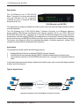
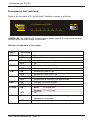
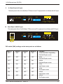
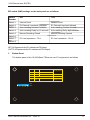
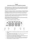
RION
TELECOM
NETWORKS
ORION TELECOM NETWORKS INC.
VCL-Ethernet over E1(FE1)
E1/10(100) Base-T Interface Converter
Data Sheet & User Manual
Headquarters: Phoenix, Arizona
Regional Office: Miami, Florida
Orion Telecom Networks Inc.
Orion Telecom Networks Inc.
16810, Avenue of the Fountains,
Suite # 108, Fountain Hills, AZ 85268 U.S.A.
Phone: +1 480-816-8672,
Fax: +1 480-816-0115
E-mail: [email protected]
Website: http://www.oriontelecom.com
4000 Ponce de Leon Blvd. Suite 470,
Coral Gables, FL 33146 U.S.A.
Phone: 1-305-777-0419,
Fax: 1-305-777-0201
E-mail: [email protected]
Website: http://www.oriontelecom.com
Orion Telecom Networks Inc. - 2009-10
1
Notice
VCL-Ethernet over E1(FE1)
Warranty
This Orion product is warranted against defects in material and workmanship for a period of one
year from the date of shipment. During the warranty period, Orion will, at its discretion, either repair
or replace products, which prove to be defective. For warranty service or repair, this product must
be returned to a service facility designated by Orion. The buyer shall prepay shipping charges to
Orion and the company shall pay shipping charges to return the product to the buyer. However, the
buyer shall pay all the shipping charges, duties and taxes for products returned to Orion from
another country.
Limitation of Warranty
The foregoing warranty shall not apply to defects resulting from improper or inadequate
maintenance by the buyer, the buyer-supplied firmware or interfacing, unauthorized modification
or misuse, operation outside of the environmental specifications for the product or improper site
preparation or maintenance.
Exclusive Remedies
The remedies provided herein are the buyer's sole and exclusive remedies. Orion shall not be
liable for any direct, indirect, special, incidental or consequential damages, whether based on
contract or any legal theory.
Notice
This manual contains information that is proprietary to Orion Telecom Networks Inc. No part of this
publication may be reproduced in any form whatsoever without prior written approval by Orion
Telecom Networks Inc.
Safety Warnings
!
The exclamation point within a triangle is intended to warn the operator or
service personnel of operation and maintenance factors relating to the product
and its operating environment, which could pose a safety hazard.
Always observe standard safety precautions during installation, operation and maintenance of this
product. Only qualified and authorized service personnel should carry out adjustment,
maintenance or repairs to this instrument. No adjustment, maintenance or repairs should be
performed by either the operator or the user.
UALITY ASSURANCE PROGRAM
Orion’s products are designed and manufactured under a strict Quality
Assurance Program based on the ISO 9001:2008 philosophy and principles.
Orion pays very special attention to its vendor development program which
ensures an “end-product” of the highest quality at the most cost effective
prices.
Orion Telecom Networks Inc. - 2009-10
2
VCL-Ethernet over E1(FE1)
Index
INDEX
Particulars
S. No.
P. No.
I
General Description
4
II
Typical Application
4
III
Technical Feature
5
IV
Installation, Open up and Commissioning
6
1.
Qualifying the network
6
2.
Grounding
6
3.
Installation
6
V
VI
VII
Function Description
7
1.
Front panel
7
2.
Back panel
8
3.
Bottom Panel
9
4.
E1 Pinout Details
10
5.
Ethernet Pinout Details
10
General Parameters
11
1.
Power Supply
11
2.
Service conditions
11
3.
Dimensions
11
4.
Ordering Information
11
Support
12
CAUTION
ELECTROSTATIC
SENSITIVE
DEVICES
DO NOT OPEN OR HANDLE
EXCEPT AT A
STATIC-FREE WORKSTATION
Orion Telecom Networks Inc. - 2009-10
3
VCL-Ethernet over E1(FE1)
Description
The VCL-Ethernet over E1-E1/10(100)
Base-T Interface Converter provides the
user with Ethernet over E1 conversion
enabling the user to transport Ethernet
data over an E1 link.
VCL-Ethernet over E1(FE1)
The equipment be always installed and used in pairs, with one terminal being installed at either
end of the network.
The VCL-Ethernet over E1-E1/10(100) Base-T Interface Converter is an Ethernet extension
device utilizing TDM telecom infrastructure (the telecom network of E1s, or of PDH, SDH and
E1/E3/SDH microwave etc. carrying E1s). It converts the Ethernet data into E1 frame format for
transmission over the existing TDM (E1) links and then re-converts the E1 back into Ethernet data
the far-end terminal, to BRIDGE two Ethernet LANs over the existing E1-based telecom network.
The device can effectively utilize the redundant bandwidth of telecom operators' existing TDM
network to transport Ethernet data with low investment.
Application
The equipment may be used for the following purposes:
!
!
!
Bridging Ethernet LANs over existing TDM (E1) telecom network.
Extending Ethernet networks utilizing TDM (E1) landline based telecom infrastructure.
Using telecom network of E1s/PDH/SDH microwave etc. carrying E1s to transport Ethernet
data.
In all cases the equipment be always installed and used in pairs, with one terminal being installed
at either end of the network.
Typical Applications
E1
E1
E1 Network
FE1/10(100)Base-T
Interface Converter
FE1/10(100)Base-T
Interface Converter
Application Diagram of FE1/10(100)Base-T Interface Converter
Orion Telecom Networks Inc. - 2009-10
4
VCL-Ethernet over E1(FE1)
Technical features
!
The maximum transmission rate of Ethernet data over E1 links is 2.048Mbit/s
!
E1 supports three working modes of transparent transmission, framed (CCS/ PCM 31) and
multiple framed (CAS/PCM30)
!
Allows transparent transmission of super-long frames in 1528 bytes (without CRC) and
supports Ethernet switches with VLAN function
!
Automatic Ethernet negotiation function. Supports 10M/100M and working modes of both
full-duplex and half-duplex
!
Available with MAC address list filtration, learning, and updating functions
!
Available with auto-resetting function. When network port stops receiving or sending data for
about 8 seconds, the auto-resetting circuit will be able to start automatically, to reduce and
maintain workload for the system
!
Equipment supports two working modes of internal clock and network clock
!
Supports RLOOP (E1 port external loop-back) function
E1 Interface Specifications
Line Rate
Framing
Electrical
Jitter
Impedance
Impedance
E1 (2.048 Mbps ± 50 bps)
Un-Framed /PCM 30 /PCM 31
As per ITU-T G.703
As per ITU-T G.823
120 Ohm (RJ-45)
75 Ohm (BNC)
Ethernet Port specifications
Interface Types
Standards Compliance
Transmission Bit Rate
Connectors
10/100BaseT
IEEE 802.3
10/100BaseT transmission rate limited
RJ-45 (10/100 BaseT Electrical)
Clock
Internal and network clock.
Orion Telecom Networks Inc. - 2009-10
5
VCL-Ethernet over E1(FE1)
Installation and Commissioning
1
Qualifying the network
!
Please ensure that the error code rate each of the E1 circuits connecting to the equipment is
-7.
lower than 10
!
The transmission time delay difference between the various E1 circuits shall not exceed 8ms.
!
The Ethernet wire type shall be, crossover when connecting with PC, and straight through
when connecting to an Ethernet switch/HUB. The length of the ethernet cable shall not
exceed 100m.
2
Grounding
!
When the device is used with the AC~220V power supply, the 3-core socket must be
grounded for protection.
!
The other equipment (e.g. optical terminal) connected with the converter shall also be
grounded to earth for protection.
3
Installation
Step 1: Power up the Ethernet over E1 equipment. Please ensure that Ethernet over E1
equipment is powered-up prior to connecting the ethernet and the E1 links.
Step 2: Connect E1 line on the premise that transmission device, interface converter and
Ethernet converter have safely grounded.
BER test may be conducted on each E1 link using a BERT tester to ensure that the E1
errors are within the permitted limits / threshold.
Step 3: Please configure the ethernet mode of the Ethernet over E1 equipment at both sides
as well as the ethernet interfaces of the devices that are connected to the Ethernet
over E1 equipment. Connect the ethernet links.
The equipment is used to bridge two LANs. Please ensure that the LANs on both
sides of the link are operating in the same IP domain.
Step 4: Ping over the ethernet connection from one side to the other (near-end to the farend) to verify that the Ethernet connection has been established between the two
LANs.
After succeeding in "ping", the user may also check the integrity of each E1 link by connecting E1
link and then transporting ethernet data over that E1 link. In the event that the Ethernet over E1
equipment resets repeatedly or lots of frame errors are noticed, recheck the connection between
E1 cable and interface converter, or E1 cable and transmission device.
Orion Telecom Networks Inc. - 2009-10
6
VCL-Ethernet over E1(FE1)
Description of the Front Panel
Figure of the front panel of E1/10(100) Bast-T interface converter is as follows:
RION
VCL-Ethernet over E1(FE1)
ON
OFF
TELECOM
NETWORKS
www.oriontelecom.com
AIS E1 ERR LINK
FDX 10M
100M CCL PWR
POWER
POWER LED: The GREEN LED indicator lights of power supply is lit under normal working
condition when the power supply is connected.
Definition of Indicators on front panel
Switch
Description
PWR
ON
System is powered
OFF
System is not powere
ON
Conflict indication on LAN port
OFF
OK
ON
Ethernet port rate is 100M
OFF
Ethernet port rate is not 100M
ON
Ethernet port rate is 10M
OFF
Ethernet port rate is not 10M
ON
Ethernet port is running in full-duplex mode
OFF
Ethernet port is running in half-duplex mode
ON
LAN port connection Normal
OFF
No LAN connection on Ethernet port
ON
Solid
E1 Signal lost
Flushing
E1 out of step
COL
100 M
10 M
FDX
LINK
E1 ERR
AIS
OFF
OK
ON
Alarm indication of opposite terminal during
transparent transmission
OFF
OK
Orion Telecom Networks Inc. - 2009-10
7
VCL-Ethernet over E1(FE1)
2
A. Back Panel: AC Input
The back panel of the 10(100) Base-T Ethernet over E1 equipment is as follows with AC Input.
1
2
TD+ TD-
SW1
AC 220V
OFF
ON
Ethernet
SW2
1 2 3 4
1 2 3 4 5 6 7 8
IN/75
-E
B.
4
5
RD+ RD-
I/O 120
OUT/75
Back Panel: 48V DC Input
The back panel of the 10(100) Base-T Ethernet over E1 equipment is as follows with DC Input
1
2
TD+ TD-
SW1
DC - 48V
+
+
+
-E
-
+
Ground
OFF
ON
Ethernet
4
5
RD+ RD-
SW2
1 2 3 4
1 2 3 4 5 6 7 8
IN/75
I/O 120
OUT/75
Positive
Negative
DIP switch (SW1) settings on the back panel are as follows:
Switch 1
OFF
Switch 2
OFF
Switch 3
OFF
Switch 4
OFF
Function
10 M/100 M Auto-negotiating
Full/Half Duplex mode
OFF
OFF
ON
OFF
10 M
Full/Half Duplex mode
OFF
OFF
OFF
ON
100 M
Full/Half Duplex mode
ON
ON
ON
OFF
10 M
Half Duplex mode
ON
OFF
ON
OFF
10 M
Full Duplex mode
ON
ON
OFF
OFF
100 M
Half Duplex mode
ON
OFF
OFF
OFF
100 M
Full Duplex mode
Orion Telecom Networks Inc. - 2009-10
8
VCL-Ethernet over E1(FE1)
DIP switch (SW2) settings on the back panel are as follows:
Switch
Number
ON
OFF
Switch 1
Internal Clock
Network Clock
Switch 2
E1 External Loop-back Forbidden
E1 External Loop-back Allowed
Switch 3
Auto-resetting function Forbidden
Auto-resetting function Allowed
Switch 4
Auto-resetting Delay by 16 seconds
Auto-resetting Delay by 8 seconds
Switch 5
Manual Resetting Closed
Manual Resetting Opened
E1 Line Impedance : 75 W
E1 Line Impedance : 120 W
Switch 6
Switch 7
Switch 8
IN 75 W Represents the E1 unbalanced 75W input.
OUT 75 W Represents the E1 unbalanced 75W Output.
3
Bottom Panel
The bottom panel of the 10(100) Base-T Ethernet over E1 equipment is as follows.
1
17
2-16, 18-32
Working Mode
SO
S16
S1-S15, S17-S31
OFF
OFF
OFF
OFF
ON
The occupied Time-slots at ON
OFF
The occupied Time-slots at ON
Unframed
Framed
Multiple Framed
ON
1
8
16 24 32
OFF
Orion Telecom Networks Inc. - 2009-10
9
VCL-Ethernet over E1(FE1)
E1 Time Slot Setup: For E1 time slot setup, the DIP Switch settings on the bottom panel
are as follows:
Working Mode
Switch Setting
Unframed
All switches are set to OFF
Framed (CCS)
S0 set to OFF, and the occupied time slots to ON
Multi-Framed (CAS)
All switches S0~S31 set to ON but S16 is set to OFF
Example 1: If you wish to use only first 5 time slots then you need to set the S0 time slots to OFF
and switch S1 to S5 to ON and time slot S16 will be set to ON.
Example 2: If you wish to carry first 8 time slots on 512Kbps, then you need to set the S0 time slot
OFF and switch S1 to S8 to ON (i.e. since each time slot consumes 64Kbps, so 8
time slots will consume 8 x 64Kbps = 512Kbps) and time slot S16 will be set to ON.
Example 3: If you wish to carry 20 time slots on 1.28Mbps (64Kbps x 20) then you need to
set time slot S0 OFF and S1 to S21 time slots to ON. Please remember that the
time slot S16 will be used as signaling time slot.
4. E1 RJ-45 to RJ-45 Crossover Pinout Details:
PIN No.
1
2
3
4
5
6
7
8
120W RJ45 pin-out
Definition of function
TX+ (transmitted data +)
TX- (transmitted data -)
NC
RX+ (received data +)
RX- (received data -)
NC
NC
NC
Signal Direction
E1 Data Output
E1 Data Output
E1 Data Input
E1 Data Input
Ethernet RJ-45 Crossover Pinouts
PIN No.
1
2
3
4
5
6
7
8
Ethernet RJ-45 Crossover Pinouts
Definition of function
TX+ (transmitted data +)
TX- (transmitted data -)
RX+ (received data +)
NC
NC
RX- (received data -)
NC
NC
Orion Telecom Networks Inc. - 2009-10
Signal Direction
Data Output
Data Output
Data Input
Data Input
10
VCL-Ethernet over E1(FE1)
General:
1
Power Supply
AC Mains Input
220V 20% (AC Mains Input Model)
Optional
2
DC Input
-48V
Power Consumption
5W
Service Conditions
Ambient temperature
00C ~ 500C
Relative humidity
90% (at 35 C)
3
Dimensions
20cm x 15cm x 4.3cm
4
Weight
750g
0
Ordering Information
S. No.
Part No.
Product Description
Qty.
1.
VCL-Ethernet over E1(FE1)- DC
10/100 Base-T (Ethernet, 1 electrical) to
1E1/FE1 (120 Ohms, 75 Ohms) Interface
Converter (with -48V DC power input)
1
2.
VCL-Ethernet over E1(FE1)- AC
10/100 Base-T (Ethernet, 1 electrical) to
1E1/FE1 (120 Ohms, 75 Ohms) Interface
Converter (with 220V AC power input)
1
Note: Operation and maintenance of network equipment require professional knowledge and
experience. We recommend the equipment to be managed only by qualified technicians.
Should you require technical assistance please consult the provider, or contact our
SUPPORT DESK at [email protected]
Orion Telecom Networks Inc. - 2009-10
11
VCL-Ethernet over E1(FE1)
Note:
Technical Specifications are subject to change without notice.
Windows is the registered Trademark of Microsoft Corporation, USA.
Revision 08 - January 16, 2010.
Headquarters: Phoenix, Arizona
Regional Office: Miami, Florida
Orion Telecom Networks Inc.
Orion Telecom Networks Inc.
16810, Avenue of the Fountains,
Suite # 108, Fountain Hills, AZ 85268 U.S.A.
Phone: +1 480-816-8672,
Fax: +1 480-816-0115
E-mail: [email protected]
Website: http://www.oriontelecom.com
4000 Ponce de Leon Blvd. Suite 470,
Coral Gables, FL 33146 U.S.A.
Phone: 1-305-777-0419,
Fax: 1-305-777-0201
E-mail: [email protected]
Website: http://www.oriontelecom.com
Orion Telecom Networks Inc. - 2009-10
12