1
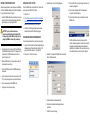
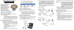
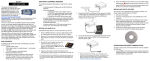
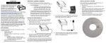
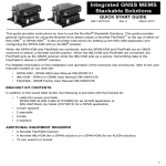
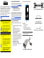
AVAILABLE USER SUPPORT DOWNLOADS
QUICK START GUIDE
In addition to this Quick Start Guide, the following user manuals
are also available from our Web site at http://www.novatel.com/
support/firmware-software-and-manuals/ for your OEMStar card:
• The OEMStar Quick Reference Guide
• The OEMStar Installation and Operation Manual
• The OEMStar Firmware Reference Manual
This guide provides the basic information you need to set up and
begin using your new OEMStar card. For more information on
the installation and operation of your receiver, please refer to the
OEMStar User Manuals. The technical specifications of the
OEMStar cards are found the OEMStar Installation and
Operation User Manual. The most up to date revisions of these
manuals can be found on our Web site at
http://www.novatel.com/support/firmware-software-andmanuals/.
WARNING:The LNA power pin (pin 1 of the 20-pin connector)
can handle a maximum voltage of 5.25 VDC.
Note: This is different from all other OEMV and SSII products
which are equipped with a 5V voltage regulator on the board.
Failure to adhere to this warning, may result in
your OEMStar card becoming permanently
damaged and void your warranty.
WARNING: Pin 3 of the OEMStar is used for the USB Dsignal.
Note: This is different from the Superstar II product
which uses pin 3 (VBATT) for external battery
backup. Superstar II users who want to integrate
the OEMStar card into existing designs must not
apply any external voltage to pin 3 and must
remove the VBATT connection.
Failure to adhere to this warning, may result in
your OEMStar card becoming permanently
damaged and void your warranty.
Figure 1 shows the card, connectors and indicators.
3
Figure 3: User-Supplied Null-Modem Cable Example
Installation programs for NovAtel’s PC utilities like CDU (Control
and Display Unit), sample source code and Universal Serial Bus
(USB) drivers with their installation instructions are all available
on our Web site at http://www.novatel.com/support/firmwaresoftware-and-manuals/firmware-software-updates/oemstar/.
2
ADDITIONAL EQUIPMENT REQUIRED
The additional equipment listed below is required for a basic
setup:
•
•
•
•
•
•
•
A Windows-based computing device with a RS-232 DB9 or USB port
A power supply between 3.3 and 5 VDC for
the OEMStar capable of providing at least 2.5 W
An enclosure to protect against environmental
conditions and RF interference
A wiring harness (see Figure 2) to provide power to the
receiver and access to the data and strobe signals, with
one or more DB-9 connectors for serial communication
with a PC or other data communications equipment
A null-modem cable (see Figure 3)
A quality GNSS antenna, such as our
ANT-35C50P1GLA-TW-N (see Figure 4)
An antenna cable with a male MCX connector at the
receiver end (see Figure 5)
]
OEMSTAR™ Card
1
Ref. #
1
2
3
Figure 4: User-Supplied Antenna
(ANT-35C50P1GLA-TW-N Example Shown)
Description
Power/data/signal connector
LED status indicator
RF signal in/LNA power out (OEMStar MCX)
Figure 1: Connector and Indicator Locations
To create a common ground, tie together all digital grounds (GND)
with the ground of the power supply.
(+)
Figure 2: Example of a User-Supplied Wiring Harness
Figure 5: User-Supplied MCX to TNC Cable Example
SETTING UP YOUR OEMSTAR CARD
INSTALLING THE PC UTILITIES
Complete the steps below to connect and power your OEMStar
card. See the OEMStar Installation and Operation User Manual
for more information on steps 2 through 5.
Once the OEMStar card is connected to the PC, antenna, and
power supply, install NovAtel’s PC Utilities.
1. Install the OEMStar card and the wiring harness in a secure
enclosure to reduce environmental exposure and RF interference, making sure to protect against ESD.
CAUTION: If you do not take the necessary
precautions against Electrostatic Discharge (ESD),
including using a suitable ESD wrist strap, you may
damage the OEMStar card and void your warranty.
2. Reconfigure the ports if necessary. COM1 and COM2 ports
on the OEMStar card support only LVTTL voltage level. You
must provide the RS-232 translation circuit in order to
connect the ports to a PC.
3. Select the New... button in the Open dialog box.
8. Select the OK button to close the dialog box and create the
new device configuration.
9. Select the new configuration from the Available device
configs list in the Open dialog box.
1. Start up the PC.
10. Select the Open button to open communications with the
OEMStar card.
2. Go to http://www.novatel.com/support/firmware-softwareand-manuals/firmware-software-updates/oemstar/ and
download the latest versions of the PC Utilities.
3. Install the PC Utilities by advancing through the steps
provided in the NovAtel PC Utilities setup program.
ESTABLISHING RECEIVER COMMUNICATION
To open communication with the receiver, follow these steps.
1. Launch CDU from the Start menu folder specified during the
installation process. The default location is Start | All Programs | NovAtel PC Software 3.x.x | NovAtel CDU
2. Select Open.... from the Device menu.
4. Select the PC serial port the OEMStar card is connected to
from the Port drop-down list.
3. Mount a GNSS antenna on a secure, stable structure with
an unobstructed view of the sky.
4. Connect the GNSS antenna to the OEMStar card using a
coaxial cable.
5. Connect a serial port on the receiver to a serial port on the
PC, or other computing device, using a null modem cable.
6. Connect a power supply to the OEMStar card.
7. Plug in and/or turn on the power supply.
5. Select desired rate from the Baud Rate list.
6. Ensure the Use hardware handshaking checkbox is
unchecked.
7. Select OK to save the settings.
As CDU establishes a communication session with the
receiver, it displays a progress box. Once CDU is connected,
the progress box disappears and several windows open,
including the Console window. CDU is now ready to be used
to view status information, enter commands, or log data.
USING CDU
CDU provides access to key information about your receiver and
its position. The information is displayed in windows accessed
from the View menu. For example, select Position Window from
the View menu to display the position solution of the receiver. To
show details of the GNSS and geostationary (SBAS) satellites
being tracked, select a Tracking Status Window (GPS or
GLONASS) from the View menu. Select Help from the main
menu for more details on CDU, its windows and features.
commands in the text box at the bottom of the Console window.
The following information is important when entering commands:
• Commands can be entered in three formats: ASCII (log
bestposa), Abbreviated ASCII (log bestpos), and Binary
(log bestposb). Abbreviated ASCII is the best format to
use when you wish to work with the receiver directly. For
data collection, use ASCII or Binary.
• Press the Enter key to send the command string to the
receiver.
• The commands are not case sensitive.
The OEMStar Quick Reference Guide provided with the receiver
lists the available commands and the parameters they use for
the Abbreviated ASCII format.
LOGGING DATA
DETERMINING WHEN THE POSITION IS VALID
When the receiver has a valid position, the POSITION VALID or
PV signal pin of the DIN connector changes to a logic level high
(LVTTL). In addition, the Solution Status field in CDU’s Position
window shows Computed.
ENTERING COMMANDS
The OEMStar cards use a comprehensive command interface.
Commands can be sent to the receiver using the Console
window in CDU, which is opened from the View menu. Enter
If you prefer, CDU provides a graphical interface for configuring
data logging. Select Logging Control Window from the Tools
menu. In the Logging Control window, you can select which logs
to capture and choose to which ports to send the data. In
addition, you can specify a file in which to save the data.
An extensive collection of logs has been created to capture the
data your OEMStar card receives and processes. These logs
can be directed to any of the OEMStar card’s serial ports and
can be automatically generated when new or changed data
becomes available or at regular intervals. The available logs are
listed in the OEMStar Quick Reference Guide.
ENABLING SBAS
The OEMStar card is capable of SBAS positioning. This
positioning mode is enabled using the SBASCONTROL command.
These commands are typically used to enable WAAS (North
America) and EGNOS (Europe) respectively:
SBASCONTROL ENABLE WAAS
SBASCONTROL ENABLE EGNOS
To log data, use the LOG command. For example, to log the
pseudorange position to COM 2 every 30 seconds, enter the
following:
LOG COM2 PSRPOS ONTIME 30
Logs can be generated in one of three formats: ASCII,
Abbreviated ASCII, or Binary. Refer to the OEMStar Firmware
Reference Manual (OM-20000126) for information on the LOG
command, specifying the output format, and the detailed
contents of each log.
Once enabled, the Position Type field shown in CDU’s Position
window should change from Single to SBAS and you may see
SBAS satellites in the Constellation window.
Refer to the OEMStar Firmware Reference Manual for more on
individual commands and logs.
USING REAL-TIME KINEMATIC (RTK) CORRECTIONS
log com2 rtcm1 ontime 5
QUESTIONS OR COMMENTS
OEMStar uses RTCM 2.3, RTCM 3.0, RTCA, Trimble CMR and
Trimble CMR+ corrections to achieve a DGPS solution. These
corrections can be transmitted from a base station to a rover
station to improve position accuracy. The base station is the
GNSS receiver which is acting as the stationary reference. It has
a known position and transmits correction messages to the rover
station. The rover station is the GNSS receiver which does not
know its exact position and can receive correction messages
from a base station to calculate differential GNSS positions.
log com2 rtcm31 ontime 5,1
If you have any questions or comments regarding your OEMStar
card, please contact NovAtel using one of these methods:
Rover: OEMStar (DGPS position only)
interfacemode com2 rtcm none off
rtksource rtcm any
psrdiffsource rtcm any
Alternative rover:
interfacemode com2 rtcm none off
rtksource rtcm any
The OEMStar supports GPS only and GPS+GLONASS RTK correction transmissions to achieve a DGPS soltution.
In most cases you need to provide a data link between the base
station and rover station (two NovAtel receivers) in order to
receive corrections. SBAS corrections can be accomplished with
one receiver and are exceptions to the base/rover concept.
Generally a link capable of at least data throughput at a rate of
9600 bits per second, and less than 4.0 s latency, is
recommended.
Once your base and rover are set up, you can configure them for
RTCA, RTCM 2.3, RTCM 3.0, Trimble CMR+ or Trimble CMR
corrections. Below is an RTCM example (replace the latitude,
longitude and height coordinates shown with those of your
base):
Base: OEMStar or other receiver
Email:
[email protected]
Web:
www.novatel.com
Phone:
1-800-NOVATEL (U.S. & Canada)
403-295-4900 (International)
Fax:
403-295-4901
psrdiffsource rtcm any
1. Refer to the GPGST log’s usage box in the OEMStar Firmware
Reference Manual for a definition of RMS and other statistics.
2. For more base/rover configurations, refer to our Web page at
http://www.novatel.com/support/knowledge-and-learning/
POST PROCESSING
Post-mission data processing refers to when the GNSS data
collected by the receiver is processed after the entire datacollection session is complete.
OEMStar output is compatible with post-processing software
from the Waypoint Products Group, NovAtel Inc. For details, visit
our Web site at:
http://www.novatel.com/products/waypoint-software/
interfacemode com2 none rtcm off
fix position 51.11358042 -114.04358013
1059.4105
GPS only DGPS base:
log com2 rtcm1 ontime 5
GPS+GLONASS DGPS base:
OEMStar Receiver
Quick Start Guide:
© Copyright 2010 NovAtel Inc. All rights reserved.
Printed in Canada on recycled paper. Recyclable.
Unpublished rights reserved under international copyright laws.
GM-14915093
Rev 2
2010/08/27