1
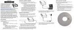
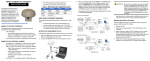
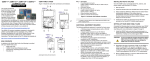
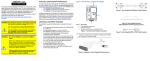
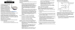
DL-V3™
QUICK START GUIDE
This guide provides the basic
information you need to set up and
begin using your new DL-V3. For
more detailed information on the
installation and operation of your
receiver, please refer to the DL-V3
User Manual on our website at
http://www.novatel.com/Downloads/
docupdates.html. To order a printed copy of the manuals, free of
charge, follow the instructions given on the enclosed User
Manuals postcard.
There are L-band and/or GLONASS-capable models available.
The DL-V3 provides additional USB and Ethernet ports and
Bluetooth® functionality. The USB drivers, along with installation
instructions, are available in the USB Drivers directory of the CD
provided. An installation program for NovAtel’s PC Utilities,
including the CDU (Control and Display Unit) user interface, and
the OEMV Software Development Kit are also on the CD.
There are LEDs on the front of the DL-V3 that show status
information on power, receiver status, COMs (COM1, COM2 and
AUX), COM3 (Bluetooth or Ethernet), satellite tracking, flash
card memory, positioning mode, and occupation time. See the
DL-V3 LEDs section of this guide.
BOX CONTENTS
In addition to this Quick Start Guide, the following is provided
with your DL-V3:
• 1 power adapter cable
• 2 DB-9 serial cables (1 straight through, 1 null-modem)
• 1 I/O cable
• 1 CD with contents as described above
• OEMV Quick Reference Guide
• User Manuals postcard to request printed manuals
• 1 64 MB Compact Flash (CF) card to use for data
storage on the DL-V3, see also the Creating a Log
Group Using DL Explorer section of this guide
ADDITIONAL EQUIPMENT REQUIRED
The additional equipment listed below is required for a typical
setup:
• A Windows-based PC/laptop with an RS-232 DB-9 or
USB port
• One of the following:
• A standard 12 VDC power adapter outlet, or
• A 9-28 VDC power supply and a power cable
with a 4-pin LEMO plug (LEMO part number
FGG.0B.304.CLAD52Z) at the receiver end1
• A quality GNSS antenna, such as NovAtel’s ANT-532-C
for airborne/high speed applications, the GPS-702L for
L-band corrections use, or the GPS-702GG for
GLONASS applications.
• An antenna cable with a TNC male connector at the
receiver end, such as NovAtel’s C016 model
6. Plug in the adapter and/or connect, turn on the power supply
and press the
button on the front face of the DL-V3. The
power LED
on the front of the receiver glows green when
the DL-V3 is turned on and properly powered.
INSTALLING THE PC UTILITIES
4. Connect the COM1, or USB, port on the receiver to a DB-9,
or USB, serial port respectively on the PC/laptop. If you are
using a USB connection, first install the USB drivers
available on the CD provided. 2
Once the DL-V3 is connected to the PC/laptop, antenna, and
power supply, install NovAtel’s PC Utilities.
1. Start up the PC/laptop.
2. Insert the accompanying CD in the CD-ROM drive of the
computer.
3. Select Install the OEMV GPS PC Utilities from the window
that is automatically displayed. If the window does not
automatically open when the CD is inserted, select Run from
the Start menu and select the Browse button to locate
Setup.exe on the CD drive.
4. Install the PC Utilities by advancing through the steps
provided in the NovAtel PC Utilities setup program.
SETTING UP YOUR DL-V3
Complete the steps below to connect and power your DL-V3.
1. Mount a GNSS antenna on a secure, stable structure with
an unobstructed view of the sky from horizon to horizon.
2. Ensure a CF card is in the slot behind the door on the front
face of the DL-V3. Open, or secure, the door by turning the
latch.
5. Line up the red mark on the power cable connector with the
red mark on the receiver’s INPUT 9-28 V connector and
insert the power cable.
Once the CF card is installed, ensure that it is
properly formatted by issuing the DISK
FORMAT command or by selecting Tools | DL
Explorer | CF Card Status in CDU. See also the
CDU sections of this guide.
ESTABLISHING RECEIVER COMMUNICATION
To open a serial port to communicate with the receiver, complete
the following:
3. Using a coaxial cable, connect the antenna to the
SAT ANT port, which is found on the back face of the DL-V3.
1.If an alternative power source is preferred, the automobile power adapter can
be cut off from the power cable. The exposed wires (red and orange for positive, brown and black for negative) can then be tied to a supply capable of at
least 5 W.
2. Before using Bluetooth or Ethernet, use a serial COM or USB
connection to communicate with the receiver. This will give you the
ability to configure the PC/laptop and DL-V3 before Ethernet or
Bluetooth use. Refer to the DL-V3 User Manual on our website at:
http://www.novatel.com/support/docupdates.htm
1. Launch CDU from the Start menu folder specified during the
installation process. The default location is Start | Programs |
NovAtel OEMV | NovAtel CDU.
2. Select Open.... from the Device menu.
6. Select 115200 from the Baud Rate list.
7. Uncheck the Use hardware handshaking checkbox.
8. Select OK to save the new device settings.
9. Select the new configuration from the Available device
configs area of the Open dialog.
3. Select the New... button in the Open dialog box. The Options
| Configuration dialog opens.
10. Select the Open button to open DL-V3 communications.
As CDU establishes the communication session with the
receiver, a progress box is displayed.
USING CDU
4. Use the
button at the top of the configurations selection
box to add a new configuration. To delete a configuration,
select it from the list and click on the
button. To
duplicate an existing configuration, click on the
button.
You can select any name in the list and edit it to change it.
CDU provides access to key information about your receiver and
its position. The information is displayed in windows accessed
from the View menu. For example, select Position Window from
the View menu to display the position solution of the receiver. To
show details of the GNSS and geostationary (SBAS) satellites
being tracked, select a Tracking Status Window (GPS or
GLONASS) from the View menu. Select Help from the main
menu for more details on CDU, its windows and features.
LED
Name
LED
Icon
Occupation
Time
Indicators
LED
Color
Green
Orange: receiver is powered
Green: receiver is turned on
1 (left)
≤5
Receiver
Status
Orange flash: at start-up
Off: normal operation
Orange flash again: status event
2
3
COM1/
COM2/
AUX
Green flash (top): transmitting
Amber flash (bottom): receiving
4
>5
≤ 10
> 10
≤ 15
> 15
≤ 20
COM3
Blue flashing: Bluetooth active
5 (right)
COM3
Orange glow: Ethernet active
Satellite
Tracking
5. Select Serial from the Type list and select the PC/laptop
port, that the DL-V3 is connected to, from the Port list.
LED#
# of
SVs
LED
Color
1 (left)
≤3
Red
2
4 or 5
Amber
3
6 or 7
Green
4
8 or 9
Green
5 (right)
≥ 10
Green
# of
LEDs
Capacity
Positioning
Mode
Green
Green
Green
≥ 20
Green
Table 1: Positioning Mode LEDs 1
Position
Mode
1
left
2
3
4
5
right
Amber
Off
Off
Off
Off
Autonomous
(3D)
Amber
Off
Off
Off
Off
SBAS
Off
Green Off
Off
Off
CDGPS
Off
Off
Green Off
Off
DGPS
Off
Green Green Off
Off
RTK (see
Float (RT-20
note below) unconverged)
Amber
Off
Off
Green Off
RTK (see
Float (RT-20)
note below)
Amber
Off
Off
Green Off
Differential
GPS
LED
Color
Position
Mode Detail
Autonomous
(fixed height)
Single
Point
1
Capacity ≤ 20%
2
40% ≥ Capacity > 20%
Red a
Amber
3
60% ≥ Capacity > 40%
Green
4
80% ≥ Capacity > 60%
Green
RTK
Fixed (RT-2,
unconverged)
Amber
Off
Off
Off
Green
5
Capacity > 80%
Green
RTK
Fixed (RT-2)
Amber
Off
Off
Off
Green
a.This red LED can also mean that the card was
not formatted, and placed in the receiver,
when the receiver was powered off.
The LEDs on the front of the DL-V3 represent these categories:
Baseline
Length (km)
Power
Flash Card
Memory
DL-V3 LEDS
LED#
See Table 1 starting on the next panel
Continued on the next panel
Continued on the next page
The LEDs show the total number of satellites used in the solution (GPS or
GPS+GLONASS) without making a distinction between GPS and
GLONASS. Check the Constellation window in CDU for details on the
availability of GPS and GLONASS satellites.
1 Table Cell Color: Solid: LED glowing; Dim: LED flashing; White: Off
•
•
•
Positioning Mode LEDs table continued from the previous page
Position
Mode
1
left
Position
Mode Detail
2
3
4
5
right
ASCII (log bestposa)
Abbreviated ASCII (log bestpos)
Binary (log bestposb).
Off
Off
VBS (pulling in) Amber Green Off
Off
Off
•
Press Enter to send the command string to the receiver.
Off
Off
•
The commands are not case sensitive.
XP (searching) Amber Off
Green Off
Off
XP (pulling in)
Amber Off
Green Off
Off
XP
Amber Off
Green Off
Off
HP (searching) Amber Green Green Off
Off
HP (pulling in)
Amber Green Green Off
Off
HP
Amber Green Green Off
Off
VBS
Amber Green Off
DETERMINING WHEN THE POSITION IS VALID
When the receiver has a valid position, the Solution Status field
in CDU’s Position window shows Computed.
ENTERING COMMANDS
The DL-V3 uses a comprehensive command interface.
Commands can be sent to the receiver using the Console
window in CDU, which is opened from the View menu. Enter
commands in the text box at the bottom of the Console window.
6. Select OK to add the new log to the log group.
Refer also to the DL-V3 User Manual, available from our website
at http://www.novatel.com/Downloads/docupdates.html, for DLV3-specific commands and logs. The OEMV Family Quick
Reference Guide, provided with the receiver, lists other OEMV
available commands and the parameters they use for the
Abbreviated ASCII format.
CREATING A LOG GROUP USING DL EXPLORER
CDU is available to download from our website at http://
www.novatel.com/support/fwswupdates.htm. DL Explorer is part
of CDU. Log groups are sets of logs used by the DL-V3. A group
can be created in DL Explorer and then uploaded to the DL-V3.
1. Launch CDU and open, or create, a DL-V3 configuration.
See the Establishing Receiver Communication section on
the first page of this guide.
2. Select DL Explorer in the Tools menu
and then select the Edit DL Groups...
button.
Within the DL Groups dialog, an empty log group is
provided. You can change its name by clicking on it and
editing it directly.
1. A red cross beside a log group name indicates the group is not
active in the DL-V3. A green check mark indicates the group is
active in the DL-V3.
2. Up to 5 log groups can be stored in the DL-V3 at any one time.
7. To log to file, select File from the Port drop-down list.
8. Repeat steps 3 through 7 to add more logs to the group.
9. Select OK in the DL Groups dialog to save the changes to
the group.
UPLOADING A LOG GROUP
Once a log group has been created, it can be uploaded to the
DL-V3. The steps below provide details on uploading a group.
1. In the DL Explorer window, select the Group Management
button.
2. Select the group to upload to the DL-V3 from the list of
groups in the CDU panel of the dialog.
3. In the Logs tab, select the log to add from the Name dropdown list.
The following information is important when entering commands:
•
Commands can be entered in three formats:
4. Select a group in the DL Groups panel and press Start on
the dialog’s right to start logging to your CF card or COM
port.
Abbreviated ASCII is the best format to use to work with
the receiver directly. For data collection, use ASCII or
Binary.
Amber Green Off
OmniSTAR VBS
(searching)
If the On Time trigger is selected, select the period for
logging using the Period drop-down list or type it in.
4. Select the log format using the Format drop-down list. You
can only use ASCII or Binary format to log to file.
5. Select the trigger for the log using the Trigger drop-down list.
3. Select the UpLoad button to copy the group.
ENABLING SBAS
DL-V3 models are also capable of SBAS positioning. This
positioning mode is enabled using the SBASCONTROL command.
These commands are typically used to enable the WAAS (North
America) and EGNOS (Europe) systems respectively:
SBASCONTROL ENABLE WAAS
SBASCONTROL ENABLE EGNOS
Once enabled, the Position Type field shown in CDU’s Position
window should change from Single to WAAS and you may see
SBAS satellites in the Constellation window. An example is
shown on the next page.
To confirm you are tracking an L-band signal, log the L-band
status information by entering: log lbandstat. For example,
if you are receiving CDGPS, the fifth field after the header
should be 00c2:
lbandstata com1 0 43.5 finesteering 1295
149951.671 00000000 976f 34461;
1547546977 46.18 4541.0 0.00 00c2 00f0 ...
To specify the correction source, use the PSRDIFFSOURCE
command as shown in the examples below:
PSRDIFFSOURCE OMNISSTAR
or,
PSRDIFFSOURCE CDGPS
otherwise it is left at the default AUTOMATIC.
Refer to the OEMV Family Firmware Reference Manual for more
on individual L-band, GLONASS or SBAS commands and logs.
REAL-TIME KINEMATIC (RTK) POSITIONING
ENABLING L-BAND
L-band equipped receivers allow you to achieve sub-meter
accuracy. To use this positioning mode, you must enable L-band
tracking to the Canada-Wide Differential GPS (CDGPS) or
OmniSTAR signal. A subscription to OmniSTAR is required to
use the OmniSTAR VBS, XP or HP service (visit http://
www.omnistar.com with your receiver serial number ready). The
CDGPS signal is free and available without subscription over
North America (visit http://www.cdgps.com).
The ASSIGNLBAND command allows you to set OmniSTAR or
CDGPS base station communication parameters. It should
include a relevant frequency and data rate. The frequency
assignment can be made in Hz or KHz. For example:
Hz:
assignlband omnistar 1536782000 1200
KHz: assignlband omnistar 1536782 1200
A value entered in Hz is rounded to the nearest 500 Hz.
Corrections can be transmitted from a base station to a rover
station to improve position accuracy. The base station is the
GNSS receiver which is acting as the stationary reference. It has
a known position and transmits correction messages to the rover
station. The rover station is the GNSS receiver which does not
know its exact position and can receive correction messages
from a base station to calculate differential GNSS positions.
In most cases, provide a data link between the base station and
rover station (two NovAtel receivers) in order to receive
corrections. SBAS and L-band corrections can be accomplished
with one receiver and are exceptions to the base/rover concept.
Generally a link capable of data throughput at a rate of 9600 bits
per second, and less than 4.0 s latency, is recommended.
Once your base and rover are set up, you can configure them for
RTCA, RTCM, RTCMV3, CMR+ or CMR corrections. Below is
an RTCM example (replace the latitude, longitude and height
coordinates shown with those of your base):
Base
interfacemode com2 none rtcm off
fix position 51.11358042 -114.04358013
1059.4105
log com2 rtcm3 ontime 10
log com2 rtcm22 ontime 10 1
log com2 rtcm1819 ontime 1
log com2 rtcm1 ontime 5
Rover
interfacemode com2 rtcm none off
RT-2 (OEMV-2 and OEMV-3) and RT-20 (OEMV-1, OEMV-1G,
OEMV-2 and OEMV-3), all with AdVance RTK, are real-time
kinematic software products developed by NovAtel. Optimal
RTK performance is achieved when both the base and rovers
are NovAtel products. However, AdVance RTK will operate with
equipment from other manufacturers when using RTCM
messaging.
RT-2 and RT-20 are supported by GPS-only and
GPS+GLONASS OEMV-based models. Also, RT-20 with
GPS+GLONASS provides faster convergence.
1. Refer to the GPGST log’s usage box in the OEMV Firmware
Reference Manual for a definition of RMS and other statistics.
2. For more base/rover configurations, search the key words
“rover base” on our Knowledge Database at:
http://www.novatel.com/support/knowledgedb.htm
EXTERNAL OSCILLATOR
For certain applications requiring greater precision than what is
possible using the on-board 20 MHz, voltage-controlled,
temperature-compensated crystal oscillator (VCTCXO), you
may wish to connect the DL-V3 to an external, high-stability
oscillator. The external oscillator can be either 5 MHz or 10 MHz.
To install, connect a cable from the external oscillator to the DLV3 port labelled EXT OSC. The receiver does not have to be
powered down during this procedure.
Once the external oscillator has been installed, issue the
EXTERNALCLOCK command to define the clock model (for
example, cesium, rubidium or ovenized crystal). If the input clock
rate is 5 MHz, you must issue the EXTERNALCLOCK command
to change the 10 MHz default rate.
POST PROCESSING
Post-mission data processing refers to when the GNSS data
collected by the receiver is processed after the entire datacollection session is complete.
OEMV-based output is compatible with post-processing
software from the Waypoint Products Group, NovAtel Inc. For
details, visit our website at:
http://www.novatel.com/products/waypoint_pps.htm
MOUNTING BRACKET
A mounting kit is provided with the DL-V3 enclosure enabling
you to mount the receiver to a surface. The mounting kit is not
designed for use in high-dynamics/vibration environments. Refer
also to its accompanying instruction sheet.
QUESTIONS OR COMMENTS
If you have any questions or comments regarding your DL-V3,
please contact NovAtel using one of these methods:
Email: [email protected]
Web: www.novatel.com
Phone: 1-800-NOVATEL (U.S. & Canada)
+1-403-295-4900 (International)
Fax:
+1-403-295-4901
Quick Start Guide:
DL-V3:
The Bluetooth® word mark and logos are registered trademarks owned by
Bluetooth SIG, Inc. and any use of such marks by NovAtel Inc. is under
license. Other trademarks and trade names are those of their respective
owners.
© Copyright 2007-2009 NovAtel Inc. All rights reserved.
Printed in Canada on recycled paper. Recyclable.
Unpublished rights reserved under international copyright laws.
GM-14915065
Rev 4
2009/03/24