1
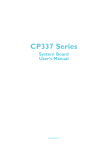
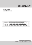
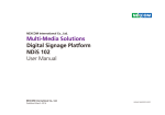
Firefly 302
Portable FireWire Unit
IMPORTANT SAFETY INSTRUCTIONS
The apparatus shall not be exposed to dripping or splashing and that no objects
with liquids, such as vases,
shall be placed on the apparatus. The MAINS plug is used as the disconnect device, the disconnect device shall
remain readily operable.
Warning: the user shall not place this apparatus in the
can be easily accessible.
area during the operation so that the mains switch
1. Read these instructions before operating this
apparatus.
CAUTION
2. Keep these instructions for future reference.
RISK OF ELECTRIC SHOCK
DO NOT OPEN
3. Heed all warnings to ensure safe operation.
. Follow all instructions provided in this document.
. Do not use this apparatus near water or in locations
where condensation may occur.
6. Clean only with dry cloth. Do not use aerosol or liquid
cleaners. Unplug this apparatus before cleaning.
. Do not block any of the ventilation openings. Install
in accordance with the manufacturer’s instructions.
8. Do not install near any heat sources such as radiators,
heat registers, stoves, or other apparatus (including
.
9. Do not defeat the safety purpose of the polarized or
grounding-type plug. A polarized plug has two blades
with one wider than the other. A grounding type plug
has two blades and a third grounding prong. The wide
blade or the third prong is provided for your safety. If
the provided plug does not into your outlet, consult
an electrician for replacement of the obsolete outlet.
10. Protect the power cord from being walked on or
pinched particularly at plug, convenience receptacles,
and the point where they exit from the apparatus.
11. Only use attachments/accessories
manufacturer.
by the
12. Use only with a cart, stand, tripod, bracket, or
table
by the manufacturer, or sold with
the apparatus. When a cart is used, use caution
when moving the cart/apparatus
combination to avoid injury from tipover.
13. Unplug this apparatus during lighting
storms or when unused for long
periods of time.
1. Refer all servicing to
service personnel.
Servicing is required when the apparatus has been
damaged in any way, such as power-supply cord or
plug is damaged, liquid has been spilled or objects
have fallen into the apparatus, the apparatus has
been exposed to rain or moisture, does not operate
normally, or has been dropped.
CAUTION: TO REDUCE THE RISK OF ELECTRIC SHOCK,
DO NOT REMOVE COVER (OR BACK)
NO USER SERVICEABLE PARTS INSIDE
REFER SERVICING TO QUALIFIED PERSONNEL
The lightning flash with arrowhead symbol, within an
equilateral triangle, is intended to alert the user to the
presence of uninsulated “dangerous voltage” within the
product’
magnitude to constitute a risk of electric shock to persons.
The exclamation point within an equilateral triangle is intended to alert the user to the presence of important operating and maintenance (servicing) instructions in the literature
accompanying the appliance.
WARNING: To reduce the risk of
or electric shock, do
not expose this apparatus to rain or moisture.
CAUTION: Use of controls or adjustments or performance
of procedures other than those
hazardous radiation exposure.
may result in
Firefly 302
Portable FireWire Unit
INTRODUCTION. . . . . . . . . . . . . . . . . . . . . . . . . . . . . . . . . . . . . . . . . . . . . . . . . . . . . . . . . . . . . . . . . . . . . . . . . . . . . . . . . . . . . . . . . . . . . 4
FEATURES. . . . . . . . . . . . . . . . . . . . . . . . . . . . . . . . . . . . . . . . . . . . . . . . . . . . . . . . . . . . . . . . . . . . . . . . . . . . . . . . . . . . . . . . . . 4
QUICK INSTALLATION.........................................................................................5
QUICK START ..................................................................................................5
FRONT PANEL DESCRIPTION....................................... . . . . . . . . . . . . . . . . . . . . . . . . . . . . . . . . . . . . . 6
REAR PANEL DESCRIPTION. . . . . . . . . . . . . . . . . . . . . . . . . . . . . . . . . . . . . . . . . . . . . . . . . . . . . . . . . . . . . . . . . . . . . . . . . . . . . 7
FIREWIRE INTERFACE. . . . . . . . . . . . . . . . . . . . . . . . . . . . . . . . . . . . . . . . . . . . . . . . . . . . . . . . . . . . . . . . . . . . . . . . . . . . . . . . . . . . 9
CHANNEL ASSIGNMENT. . . . . . . . . . . . . . . . . . . . . . . . . . . . . . . . . . . . . . . . . . . . . . . . . . . . . . . . . . . . . . . . . . . . . . . . . . . . . . . .1 5
OPERATING WITH DAW SOFTWARE....................................................................... 15
FIREFLY CONTROL PANEL...................................................................................16
APPLICATION. . . . . . . . . . . . . . . . . . . . . . . . . . . . . . . . . . . . . . . . . . . . . . . . . . . . . . . . . . . . . . . . . . . . . . . . . . . . . . . . . . . . . . . . . . . . . . 1 9
SPECIFICATIONS. . . . . . . . . . . . . . . . . . . . . . . . . . . . . . . . . . . . . . . . . . . . . . . . . . . . . . . . . . . . . . . . . . . . . . . . . . . . . . . . . . . . . . . . . 2 1
DIMENSIONS. . . . . . . . . . . . . . . . . . . . . . . . . . . . . . . . . . . . . . . . . . . . . . . . . . . . . . . . . . . . . . . . . . . . . . . . . . . . . . . . . . . . . . . . . . . 2 2
BLOCK DIAGRAM. . . . . . . . . . . . . . . . . . . . . . . . . . . . . . . . . . . . . . . . . . . . . . . . . . . . . . . . . . . . . . . . . . . . . . . . . . . . . . . . . . . . 2 3
Phonic preserves the right to improve or alter any information within this document without prior notice.
V1.1 JUL 21st, 2008
Introduction
Features
Congratulations on your purchase of one
of the newest FireWire-enabled products from Phonic, the Firefly 302 Plus.
Through the Firefly’s ultra low-noise
microphone input and two line inputs,
together with a FireWire interface, users
are able to digitally transfer their audio
to a computer in high resolution (96
kHz) audio that meets today’s modern
production standards. Never again will
you have to worry about loss of audio,
as the Firefly will be the only tool you
need to transfer those analog recordings to digital. Light, easy to use, with
no problematical configuration needed,
the Firefly certainly shines when it comes
to simplicity and mobility. Size certainly
doesn’t matter, because big things will
come from your Firefly.
● 24-bit / 96 kHz sampling rate
We know how eager you are to get
started – wanting to get the product out
of the box and hook it all up is probably
your number one priority right now – but
before you do, we strongly urge you to
take a look through this manual. Inside,
you will find important facts and figures
on the set up, use and applications of
your brand new Firefly. If you do happen
to be one of the many people who flatly
refuse to read user manuals, then we
just urge you to at least glance at the
Quick Installation and Setup sections.
After glancing at or reading through
the manual (we applaud you if you do
read the entire manual), please store
it in a place that is easy for you to find,
because chances are there’s something
you missed the first time around.
● Powered via FireWire bus or DC
● 2 x analog line I/O: 1/4” TRS, RCA
● 1 x Mic: XLR with 48V phantom
power
● Two convenient high-bandwidth
FireWire 400 ports (4-pin and 6-pin)
● Digital S/PDIF (coaxial) I/O (PCM)
● Front-panel microphone in (XLR) with
48V phantom power
● Headphone output with dedicated
level control
● Zero-latency hardware direct monitor-
ing
● Low-latency ASIO software direct
monitoring
● 1 x 1 16-channel MIDI I/O
● Power on/off indicator LED
power supply
● Easy-to-see sig and clip LED indica-
tors
● Mac and Windows compatible
Firefly 302
Quick Installation
Quick Start
1. Turn your computer on and connect
the Firefly 302 Plus to the computer
via the FireWire interface. Turn the
Firefly on by setting the power select
switch to DC IN - if using the 4-pin
connector and DC power supply - or
BUS - if using the 6-pin connector.
1. Connect the DC converter to the 912V jack in and change the power
selector switch to the DC IN position
(if using the 4-pin FireWire connector.
This is usually used with Notebook
computers). Alternatively, change
the power selector switch to BUS,
and use the Firefly’s 6-pin FireWire
connector.
2. Run the setup.exe file on the included
driver CD, and follow the installation
instructions displayed on screen.
3. When prompted to “disconnect and
reconnect” the Firefly, change the
power select switch on the rear of the
device to OFF, then to DC IN (4-pin)
or BUS (6-pin).
4. Continue to follow the on-screen
installation instructions.
5. Open your audio editing / DAW software, and check the Firefly’s ASIO
driver has been read successfully by
the program. This is usually one in the
“Devices” submenu. You may also
want to edit the Firefly’s properties.
This is usually done by clicking on the
Tools pull down menu, and selecting
“Properties”. In this area, you can
usually select the Firefly’s different
inputs and outputs, and assign them
to various channels. This, of course,
depends on the software you are
using, so check the software’s user’s
manual for more information.
Firefly 302
2. Plug your FireWire cable into Firefly’s
and your Computer’s FireWire ports.
The computer should detect your
Firefly 302 Plus.
3. Connect a microphone to the XLR
input connector. Talk into the mic and
check the LED level meter; adjust the
Mic level control as you see necessary.
4. Connect any analog inputs you wish
to use. Remember that using the
corresponding RCA and 1/4” inputs
simultaneously will mix the signals,
and sount terrible; you’re better off
using only one at a time.
5. Open your audio software and configure it so the Firefly 302 Plus is set as
your input/output device. Please note
that the analog and S/PDIF outputs
cannot be used to output the signal
from the computer simultaneously.
6. Plug your headphones into the headphone output of the Firefly to monitor
the return signal.
7. Now you are ready to design high
resolution audio productions.
1
2
3
6
Front Panel Description
1. Power LED Indicator
5. Gain 1 and 2
When you connect the DC power converter
and change the power switch to the DC IN
(or BUS, if using the 6-pin FireWire connector) position, the unit will be powered
and the front power LED will be illuminated
giving you an indication that your Firefly is
on and running.
This knob controls the input gain for the
RCA and 1/4” plug input jacks located
on the rear panel. Turn then clockwise to
increase the signal level gain or turn them
counterclockwise to lower the input levels.
Gain 1 controls the Analog In RCA 1 and
1/4” TRS 1 input jacks, and Gain 2 controls
the Analog In RCA 2 and 1/4” TRS 2 input
jacks. Each gain control is independent so
you can easily match your input levels.
2. Headphone Output Jack and Control
All the audio signals that are mixed on
computer can be monitored with the Headphone output. You can also control this
level with the corresponding level control.
3. XLR Microphone Connector
This is a balanced microphone XLR 3-pin
connector, which you can use to connect
dynamic or condenser microphones.
Phantom power may be applied to these
connectors to allow all condenser or ribbon
microphones to be connected.
4. Mic Gain
Turn this knob clockwise to increase the
Microphone input’s gain. You have 44dB
of possible gain with this knob, so please
take care when applying gain to ensure Mic
Clip LED does not light up.
6. +48V Phantom Power
Pushing this button will activate +48V of
phantom power on the microphone input,
allowing users to connect condenser
microphones, ribbon microphones, or
devices that need +48V power to work
properly. If you are not sure if your mic
requires phantom power, please refer to
the microphone’s owner’s manual.
7. Sig / Clip Indicators
These LED indicators give users an idea of
when their analog and mic inputs and outputs are receiving a signal (sig) and when
that signal reaches high peaks just prior
to the signal being dynamically clipped,
which may cause undesirable effects to
your audio integrity (clip).
Firefly 302
8
9
10
11
12
13
1
1
16
Rear Panel Description
8. Analog 1/4” TRS Inputs 1 and 2
10. Analog 1/4” TRS Outputs 1 and 2
These are balanced 1/4” TRS Line Inputs
and can be used to connect any line level
devices, such as CD players or DAT recorders.
This are balanced 1/4” TRS Line Outputs
with line level signal (+4dBu). Use them to
get a stereo output channel and connect
them to active monitors (such as the Phonic P8A), or perhaps to an amplifier and a
passive pair of speakers. You could also
use them with several signal processor or
any external devices.
9. Analog RCA Inputs 1 and 2
These are RCA inputs and can be used to
connect any device like CD players, DAT
recorders, turntables, and even analog
mixers (taking the signal from a mixer’s
Record or 2-Track outputs).
Important Note: Keep in mind that the two
RCA inputs are completely independent of
one another; however these inputs should
not be used if the 1/4” analog 1 and 2
inputs are used, as doing so may cause
irreversible damage to the Firefly. You can,
however, mix and match these inputs. If, for
example, you wanted to use RCA input 1
and 1/4” input 2 that would not cause any
problems.
Firefly 302
11. Analog RCA Outputs 1 and 2
These are RCA line outputs. They accept
RCA cables and can be connected to any
external device that uses this connector
type (tape recorders, MP3 recorders,
etc.).
12. S/PDIF In/Out
These are a standard S/PDIF Digital Audio
Input/Outputs that can be use with digital
mixers, DAT recorders, or any external
device that uses RCA Digital interface
format. The S/PDIF’s output sampling rate
is determined by the sampling rate set by
the Firefly control software. Please use a
75 ohms coaxial cable with RCA plug if you
are using the S/PDIF connection, as the
most common problems associated with
glitches in digital interfaces are the result
of use of using poor quality cable.
8
9
10
11
12
13
1
1
16
13. MIDI In/Out
16. Power Selector Switch
You can have 16 simultaneous MIDI
input/output channels sent to and from
your computer through the Firefly 302
Plus.
This switch gives users three operation
options: DC IN will turn on the Firefly
using the DC input power; PWR OFF
will turn the Firefly off, and; BUS will
allow the Firefly to use Power provided
through the 6-pin FireWire connection.
14. FireWire Ports
This is a digital FireWire (a.k.a. PC
IEEE 1394) interface that you can use
to connect to your computer. Doing so
allows users to send their audio signal
from the Firefly to the Computer, and
vise-versa. There are both the 4-pin and
6-pin varieties available – the difference
being the 6-pin will allow you to power
the Firefly through the Firefly connection
(provided the Power Selector Switch is
set to ‘BUS’).
15. 9-12VDC Input Power Jack
Connect the supplied DC converter to
this jack to feed the unit. Please only
use this DC converter in order to ensure
no damage is done to the Firefly. If, for
any reason, your converter gets lost
or damaged and you need a new one
please contact your local dealer. This
option lets you work on the road without
draining your laptop’s battery.
Firefly 302
FireWire Interface
System Requirements
The following are the minimum required specifications for use with the Firefly. If your
computer does not meet these requirements, you will experience lagging of audio and
possible freezing of your computer when attempting to operate the Firefly.
Windows
•
•
•
•
•
Microsoft® Windows® XP SP1 and SP2
Available FireWire port
Intel Pentium® 4 processor or equivalent AMD Athlon processor
Motherboard with Intel or VIA chipset
5400 RPM or faster hard disk drive (7200 RPM or faster with 8 MB cache recommended)
• 256 MB or more of RAM (512 MB recommended)
Macintosh
• OS X 10.3.5 or later with native FireWire support
(OS X 10.4.7 may have some stability issues)
• G4 or newer processor
• 256 MB or more of RAM
Driver Installation
To use the Firefly efficiently (or at all) on a PC, it is important to install all the necessary
drivers from the included CD1 (ASIO and WDM drivers). It is important that users read
all instructions carefully before continuing on to the each step of installation, as users
will be required to unplug and plug in their FireWire device. This is not necessary for
Mac users.
Windows XP (with Service Pack 1 or 2)
1. It is recommended that you quit all applications before starting the installation process.
2. Ensure the Firefly is not yet connected to your Computer’s FireWire input.
3. Insert the installation CD included with your Firefly into the CD-ROM drive of your
computer. If the CD does not automatically start the installation process within a
few moments, then navigate to “My Computer” g your CD-ROM drive g “Drivers
and Control Panel Firefly 302 Plus” g double-click “setup.exe” to begin the installation manually. The Firefly Control Panel software also will be installed at this time.
4. Follow the on-screen installation instructions.
Firefly 302
Make sure no other programs are running on your PC and click “Next”.
Read and accept the terms of the License Agreement and click “Yes” to continue.
10
Firefly 302
Either select a new destination for the installation,
or else click “Next” to accept the default directory.
Click “Next” to begin the installation.
Firefly 302
11
Disconnect and reconnect the Firefly 302 PLUS (or simply turn it off and then on again).
If a message is displayed indicating that the software has not passed
Windows Logo test,click “Continue Anyway”.
After installation is complete, users are free to use the device as they wish.
12
Firefly 302
Macintosh OS X (10.3.5 or later)
The Firefly 302 Plus works with the primary audio drivers of Macintosh OS X 10.3.5 and
later. First verify that you are running Macintosh OS X 10.3.5 or above, then connect the
Firefly 302 Plus to a FireWire port to the computer. To ensure your Firefly 302 Plus is
working, enter the Utilities folder and double-click the Audio MIDI Setup icon.
Enter the Audio Device’s section. From the “Properties for” pull-down tab, select
Firefly 302 Plus.
At the bottom of the window, users can edit the setup of the Firefly 302 Plus.
Properties such as sampling rate and clock source can be altered.
Users may also opt to make the Firefly 302 Plus their default input and/or output device.
Firefly 302
13
Mac users are able to use GarageBand Digital Audio Workstation Software,
in conjunction with the Firefly 302 Plus.
14
Firefly 302
Channel Assignment
Operating With DAW Software
When using a Digital Audio Workstation
on a PC, and within the included Phonic
Firefly 302 Plus control panel software,
the following names have been attributed to the input channels of the FireWire
mixer. They can be altered through the
control panel software included with the
mixer.
After successfully completing the installation
process, the following process must be followed to work efficiently with the Firefly 302
Plus mixer. The information supplied below
is for Steinberg’s Cubase software, however
does not differ significantly to other DAW
programs.
Channel Name
Firefly Channel
Analog In 1
1/4” and RCA Analog Input 1
Analog In 2
1/4” and RCA Analog Input 2
Mic In
Microphone Input
Mic In
Microphone Input
S/PDIF In
S/PDIF Input
S/PDIF In
S/PDIF Input
Midi In
MIDI Input
To alter an input channel’s name on your
computer, open the Firefly 302 Plus control panel software. On the left hand side
of the control panel, users will find the settings categories. By clicking “Input Channels”, the main window will display the
titles input channels. You can then highlight the channel names and press the
“Edit Channel Name” button on the bottom of the control window. A new window
will appear that will allow users to adjust
the channel name.
If you would like to use the Firefly 302 Plus
as your default audio output device on
you PC, simply go into the Windows control panel, and select “Sound and Audio
Devices”. Select the Audio tab, and use
the pull-down menu to select the Firefly
302 Plus from the list of available output
devices. The Firefly 302 Plus can also be
selected as the default output device for
individual programs by editing said programs’ settings / options.
Firefly 302
1. Open your DAW program.
2. Go to the ‘Devices’ pull-down menu and
select ‘Device Setup’. On the left, select
‘VST Multitrack’.
3. From the ASIO Driver device list select
the ‘Phonic ASIO’ Driver. A pop-up box
will ask you if you want to switch the ASIO
driver. Click ‘Switch’. This completes the
basic installation and setup.
4. To activate the various audio tracks received from the Firefly 302 Plus:
a. Go to the “devices” pull-down menu
and select ‘VST Inputs’. This will
display the various available inputs
(“Analog In 1”, “Analog In 2”, etc.).
b. Activate these channels by clicking
the “Active” button (or your DAW’s
appropriate button) located next to
each channel name.
5. For further instructions on the operation
of your DAW software, please consult
your software’s appropriate documentation (setup guides, operation manuals,
etc.).
If you wish to reset the Firefly 302 ASIO
driver, simply go to the ‘devices’ pull-down
menu and select ‘device setup’. Simply click
“reset” and select the “Phonic ASIO Driver”.
Click ‘ok’ to continue and the Firefly 302 Plus
should once again become functional.
15
Firefly Control Panel
The Firefly control panel can be accessed
at any time by entering choosing the
shortcut from your Programs menu. This
program will not only allow users to alter
their device and channel names and properties, but will also let them correct for latency issues, change sampling rates, and
so forth. When opening the software, a
number of options will be available for users to select from, allowing them to adjust
the available properties.
Input Channels
The Input Channels section allows users
to view and edit the name of the various
input channels received from the FireWire
input. For a list of default channel names,
please consult the table on page 12.
Devices
In the Devices section, users are able
to view and edit the name of the Phonic
FireWire Devices connected to their computer.
Output Channels
By entering the Output Channels section,
users can view and edit the names of the
two output channels from the computer to
the Firefly mixer.
16
Firefly 302
Synchronization
In the Synchronization section, users can
adjust the sampling rate and other synchronization properties. Many of these
adjustable properties, as they are, are set
for optimum performance and, unless you
are sure of what you need to change, are
probably best left alone.
First off, the synch mode can be altered,
though making this alteration is not recommended for novice users. The synch
mode is basically the way the computer
determines what the ‘clock source’ (ie.
device that your computer will use to
determine the timing of all digital signals
received) will be. The default setting for
this feature is “CSP”, meaning the Firefly
is the “master” clock source of the device.
The other options allow users to make the
Firefly follow the “timing” of whichever device is the clock source. Having two clock
sources has the potential to create very
undesireable audio, so it is best avoided.
If the Firefly 302 PLUS is the only piece
of digital audio equipment attached to the
computer, there is no reason this option
should be changed.
Firefly 302
If you wish to use the S/PDIF input, simply
double-click on the “302” in the devices
menu. The Device Synchronization Mode
window that will then appear allows users
to select the External Clock (Ext. S/PDIF
Input) as the default clock source.
Also in Synchronization, users are also
able to change between automatic and
manual sampling rate settings. When
the sampling rate is manually set, users
can select between sampling rates of
44.1, 48.0, 88.2 and 96.0 kHz per second.
Many devices have sampling rates that do
not surpass 44.1 kHz per second, therefore, when using multiple digital devices,
users are advised not to exceed this level
unless they are sure the secondary device’s sampling rate can .
17
Settings
Streams
Users are able to adjust various buffer
times in the Settings section.
In the Streams section, the Firefly 302
PLUS device properties can be viewed.
Each input and output stream can be
scrutinized, and the isochronous stream
number and its supported sampling rates
can be viewed.
The Stream Buffer Depth is adjustable between 0.5 and 20 milliseconds. It adjusts
the buffer used when streaming a signal
from the Firefly 302 PLUS. If the depth is
set too high, an obvious latency will become evident. If the depth is too low, various clicks and pops may become obvious.
It is best to set the Stream Buffer Depth to
a level that allows users to get the lowest
latency, while still maintaining an optimal
performance. The default settings are
ideal for most computers.
The ASIO Buffer Depth is adjustable between 4 and 40 milliseconds. This allows
users to adjust the latency of the stream
received by ASIO driver-based software
(including Steinberg Cubase LE).
The WDM (Windows Driver Model) Sound
Buffer Depth is adjustable between 4 and
40 milliseconds. This allows users to adjust the latency of the stream received by
WDM based programs.
Also in this section, users are able to view
their “drop out statistics”, where the number of times the FireWire connection has
been interrupted can be viewed.
18
Firefly 302
Application
Mobile Studio Recording
ACTIVE
MONITORS
HDM1.8
HDM1.8
GUITAR
GUITAR EFFECTS
KEYBOARD
DRUM MACHINE
HEADPHONE
Firefly 302
LAPTOP COMPUTER
MICROPHONE
19
Turning Analog Recordings Digital
Audio Cassette Player
or LP Player
HEADPHONE
LAPTOP COMPUTER
20
Firefly 302
Specifications
Line Inputs
Connectors
1/4” TRS, RCA
Max input (balanced)
+10 dBu
Max input (unbalanced)
+10 dBu
Input gain range
-∞ to +10 dBu
Impedance
10K Ohm (Unbalanced), 20K Ohm (Balanced).
Microphone Input
Connectors
XLR
Available gain
44dB
Input range:
-40 ~ -+4 dBu
Impedance
2k ohm
Line Outputs
Connectors
1/4” TRS, RCA
Max output (balanced)
+8 dBu
Max output (unbalanced)
+2 dBu
Impedance
100 Ohm (Unbalanced), 200 Ohm (Balanced)
System
Signal-to-noise ratio
-90.6 dB @ 48 kHz (A-WEIGHTING)
THD + N
0.002% 1 kHz, @ 48 kHz
Frequency response
20 Hz to 20 kHz @ 48 kHz,+0.03/-0.23 dB
Crosstalk
-72 dB (A-WEIGHTING)
S/PDIF Input and Output
Connector
Coaxial RCA
Sample rates
44.1, 48, 88.2, 96 kHz
Headphone Outputs
Max output
+2 dBV (1.3Vrms) into 32 ohms
Physical Attributes and Power
Power supply
DC 9 ~12V (AC to DC adaptor) / FireWire Bus Power
Dimensions (W x D x H)
196 x 130 x 44 mm / 7.7” x 5.1” x 1.7”
Weight
0.9 kg / 1.98 lbs
Firefly 302
21
Dimensions
196 / .
1 / 6.1
1 / 6.1
1 / 2
measurements are shown in mm/inches
22
Firefly 302
Firefly 302
1394
P OW ER
P HY
CL OC K
1394b link layer controller
Me mor y
MIDI IN
MIDI OUT
S/PDIF IN
S/PDIF OUT
M IC IN
ANALOG IN
ANALOG OUT
MIDI IN/OUT
S/PDIF IN/OUT
A/D
Converter
A/D
Converter
D /A
Converter
MIC IN
RCA IN
Balance IN
Headphone OUT
RCA OUT
Balance OUT
Block Diagram
23
6103 Johns Road #7