1
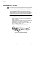
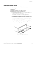
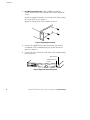
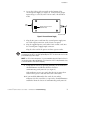
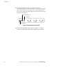
® Powerware Expansion Chassis User’s Guide www.powerware.com Powerware is a registered trademark and X-Slot is a trademark of Powerware Corporation. Modbus is a registered trademark of Modicon. . Copyright 2002 Powerware Corporation, Raleigh, NC, USA. All rights reserved. No part of this document may be reproduced in any way without the express written approval of Powerware Corporation. CHAPTER 1 INSTALLATION The Powerware9 Expansion Chassis is a connectivity device that contains a Modbus9 Card and two slots for other X-SlotZ connectivity devices, providing greater power management control and flexible monitoring. Refer to the respective user’s guide for operation of the X-Slot cards to be used in the chassis. Inspecting the Equipment If any equipment has been damaged during shipment, keep the shipping cartons and packing materials for the carrier or place of purchase and file a claim for shipping damage. If you discover damage after acceptance, file a claim for concealed damage. To file a claim for shipping damage or concealed damage: 1) File with the carrier within 15 days of receipt of the equipment; 2) Send a copy of the damage claim within 15 days to your service representative. Safety Precautions Read the following precautions before you install the Expansion Chassis. CAUTION : To reduce the risk of fire or electric shock, install the chassis in a temperature and humidity controlled, indoor environment, free of conductive contaminants. Ambient temperature must not exceed 40C (104F). Do not operate near water or excessive humidity (95% max). : For rack installations only. The rack should be connected to a reliable earth ground in accordance with local regulations. Powerware® Expansion Chassis User’s Guide : 164201336 Rev A Uncontrolled Copy 3 Installation Installing Additional X-Slot Cards NOTE Refer to the individual X-Slot card user’s guide before installation. There may be specific instructions that need to be completed first, such as changing default jumpers. Also verify that the X-Slot card you are using with the chassis is compatible with the communication port on your UPS. For the Powerware 9315 UPS. The Powerware 9315 UPS is not compatible with the Relay Interface Adapter or the Single Port Serial Card. Both cards require open collector signals (AC Fail and Low Battery), and the 9315 only provides RS-232 serial data through the communication port. Only the RS-232 capability of the Single Port Serial Card is supported. Refer to the UPS user’s guide for more information. The Modbus Card is factory-installed in Slot 1 and must remain in Slot 1. To install additional X-Slot cards: 1. Remove the X-Slot cover on the chassis rear panel. Retain the screws (see Figure 1). 2. To prevent electrostatic discharge (ESD), place one hand on an unpainted metal surface such as the UPS rear panel. Align the X-Slot card with the slot guides and slide the card into the slot until it is firmly seated. 3. Secure the card with the screws removed in Step 1. Figure 1. Installing Additional X-Slot Cards 4 Powerware® Expansion Chassis User’s Guide : 164201336 Rev A Uncontrolled Copy Installation Installing the Expansion Chassis The Expansion Chassis can be installed three different ways: : as a freestanding device : wall-mounted : rack-mounted, using only 1U of valuable rack space To install the chassis, perform the following steps: 1. Freestanding Installations Only. Attach the supplied adhesive feet to the bottom corners of the chassis. Position the chassis close to your UPS. Skip to Step 4. 2. Wall-Mount Installation Only. Using a Phillips screwdriver, remove the four screws on each side of the chassis. Retain the screws. Attach the supplied wall brackets to each side of the chassis using the removed screws (see Figure 2). The chassis may be mounted in either orientation to the wall. Attach the chassis to the wall using customer-supplied screws and wall anchors. Skip to Step 4. Figure 2. Attaching the Wall Bracket Powerware® Expansion Chassis User’s Guide : 164201336 Rev A Uncontrolled Copy 5 Installation 3. Rack-Mount Installations Only. Using a Phillips screwdriver, remove the four screws on each side of the chassis. Retain the screws. Attach the supplied L-brackets to each side of the chassis using the removed screws (see Figure 3). Mount the chassis in the rack. Continue to Step 4. Figure 3. Attaching the L-Bracket 4. Connect the supplied serial cable (Powerware part number 124102022) to the communication port on the chassis rear panel (see Figure 4). 5. Connect the other end of the serial cable to the communication port on the UPS. Input Connectors Communication Port (to UPS) Figure 4. Expansion Chassis Rear Panel 6 Powerware® Expansion Chassis User’s Guide : 164201336 Rev A Uncontrolled Copy Installation 6. Locate the Voltage Selector switch on the bottom of the external power supply (see Figure 5). Verify that the proper input voltage is selected (either 115 or 230V). The default is 230V. Input Connector Voltage Selector Switch (230V Position) DC Power Cord Figure 5. External Power Supply 7. Plug the DC power cord from the external power supply into one of the input connectors on the chassis rear panel. 8. Plug the supplied power cord (either 110V or 220V cord) into the external power supply input connector. Plug the other end of the power cord into a power outlet. NOTE It is recommended that you plug the power supply cord into one of the outlets on the back of your UPS or an outlet powered by the UPS. This allows the chassis to be protected during a power outage. NOTE For UPSs with load segments, it is recommended to plug the Expansion Chassis into the last group to be powered down. This allows the chassis to be powered as long as the UPS before it shuts down completely. 9. Verify that the chassis is operating normally; the X1 indicators should illuminate and flicker when the chassis is communicating with your UPS (see Figure 6). If the indicators are not on, verify that the UPS is powered on and check the power cord and serial cable connections. 10. If you installed additional X-Slot cards, the X2 and X3 indicators (for Slot 2 and Slot 3, respectively) should illuminate and flicker when the chassis is communicating with your UPS. Powerware® Expansion Chassis User’s Guide : 164201336 Rev A Uncontrolled Copy 7 Installation 11. In some situations, it may be necessary for a UPS to communicate directly to the card in Slot 3 instead of the default Slot 1 card. In this case, attach the UPS to the communication port on the chassis front panel and move the switch to the AUX position (see Figure 6). UPS Communication Port Power Indicator 1 NORM AUX 2 X3 1 2 X2 1 2 X1 Auxiliary Switch Figure 6. Expansion Chassis Front Panel 12. Refer to the individual X-Slot card user’s guide to set up the card for communication with your serial devices or network. 8 Powerware® Expansion Chassis User’s Guide : 164201336 Rev A Uncontrolled Copy CHAPTER 2 TROUBLESHOOTING Problem Possible Cause Corrective Action The Power indicator is not on. The power cord is not connected. Verify the power cord connections are secure. The UPS is not powered on. If the power cord is plugged into the UPS, verify that the UPS is powered on. If the first indicator is not on, the chassis may need to be reset. Unplug the power cord from the chassis for several seconds, then plug the power cord back in. Xn indicators are not on. If the second indicator is not Verify that the serial cable is securely attached to on, the UPS is not responding. the chassis and to the UPS. Verify that the UPS is powered on. Service and Support If you have any questions or problems with the Expansion Chassis, call your Local Distributor or the Help Desk at one of the following telephone numbers and ask for a Expansion Chassis technical representative. In the United States: Europe, Middle East, Africa: Asia: Australia: 1-800-365-4892 or 1-919-870-3149 +44-17 53 608 700 +852-2830-3030 +61-3-9706-5022 Please have the following information ready when you call the Help Desk: : : : : Model number Date of failure or problem Symptoms of failure or problem Customer return address and contact information Powerware® Expansion Chassis User’s Guide : 164201336 Rev A Uncontrolled Copy 9 Troubleshooting If repair is required, you will be given a Returned Material Authorization (RMA) Number. This number must appear on the outside of the package and on the Bill Of Lading (if applicable). Use the original packaging or request packaging from the Help Desk or distributor. Units damaged in shipment as a result of improper packaging are not covered under warranty. A replacement or repair unit will be shipped, freight prepaid for all warrantied units. NOTE For critical applications, immediate replacement may be available. Call the Help Desk for the dealer or distributor nearest you. 10 Powerware® Expansion Chassis User’s Guide : 164201336 Rev A Uncontrolled Copy Troubleshooting Two-Year Limited Warranty (US and Canada Only) Powerware Corporation warrants the electronics of the Expansion Chassis to be free from defects in material and workmanship for a period of two years from Date of Purchase. If, in Powerware Corporation’s opinion, the electronics fails to meet its published specifications due to a defect in material and workmanship covered by this warranty, Powerware Corporation will repair or replace the warranted Unit at no cost to the customer for parts and labor. Equipment supplied by Powerware Corporation, but not manufactured by Powerware Corporation, is warranted solely by the manufacturer of such equipment. Powerware Corporation does not warrant equipment not manufactured by Powerware Corporation. This warranty does not apply to any Unit that has been subject to neglect, accident, abuse, misuse, misapplication, incorrect connection or that has been subject to repair or alteration not authorized in writing by Powerware Corporation’s personnel. THIS WARRANTY IS THE PURCHASER’S (USER’S) SOLE REMEDY AND IS EXPRESSLY IN LIEU OF ANY OTHER WARRANTY, AND THERE ARE NO OTHER EXPRESSED OR IMPLIED GUARANTEES OR WARRANTIES (INCLUDING ANY IMPLIED WARRANTY OF MERCHANTABILITY OR FITNESS FOR PURPOSE). In no case will Powerware Corporation’s liability under this contract exceed the value of the Unit furnished. In no event shall Powerware Corporation be liable for any indirect, incidental, special or consequential damages. Powerware Corporation shall not be responsible for failure to provide service or parts due to causes beyond Powerware Corporation’s reasonable control. THIS LIMITED WARRANTY IS VOID UNLESS USER RETURNS TO POWERWARE CORPORATION THE INCLUDED WARRANTY REGISTRATION CARD WITHIN THIRTY (30) DAYS OF DELIVERY. Any advice furnished the Purchaser (User) before or after delivery in regard to use or application of Powerware Corporation equipment is furnished without charges and on the basis that it represents Powerware Corporation’s best judgement under the circumstances. The use of any such advice by the Purchaser (User) is solely and entirely at his or her own risk. This limited warranty applies only to equipment installed in the fifty United States of America and Canada. In other countries, consult your local distributor. Extended Service Coverage A full complement of warranty extensions and enhancements are available from Powerware Corporation for your UPS. Information pertaining to these services should be available in the shipping container along with this manual. If not, or if you would like more information, call the Powerware Corporation Help Desk and ask about warranty services. Powerware® Expansion Chassis User’s Guide : 164201336 Rev A Uncontrolled Copy 11 Troubleshooting International Limited Warranty Powerware Corporation warrants the electronics modules manufactured by Powerware Corporation (“Unit”) and batteries originally packaged in the Unit or in battery packs manufactured by Powerware Corporation against defect in material or workmanship until the earlier of: (1) 18 months from date of shipment or (2) 12 months from date of initial start-up is performed by Powerware Corporation field personnel or field personnel authorized by Powerware Corporation to carry out such service efforts on its behalf and provided that, startup occurs no later that 6 months after shipment. If the unit does not function in accordance with its published specification, the user should give Powerware Corporation prompt notice thereof and if requested by Powerware Corporation, the user shall return the warranted Unit or parts thereof to the plant or service station designated by Powerware Corporation for inspection by Powerware Corporation. Any Unit which may require repair and/or replacement of parts as the result of defects in workmanship or material within the stated warranty period, will be replaced or repaired at Powerware Corporation’s option without charge for replacement parts. The cost of shipment, duties or all other expenses associated with shipment of repaired or replaced items is for the account of the user. Powerware Corporation will not be responsible or liable for work done or expense incurred in connection with repair or replacement except as expressly authorized by Powerware Corporation, Raleigh, NC, USA in writing. If a service engineer is required, labor, at current published rates, and all travel and living expenses are for the account of the user. Powerware Corporation does not warrant equipment not manufactured by Powerware Corporation including any battery not originally packaged with the Unit or in battery packs manufactured by Powerware Corporation. The manufacturer of all such equipment shall solely warrant that equipment and Powerware Corporation shall have no responsibility or liability thereof. IT IS AGREED THAT POWERWARE CORPORATION, ITS PARENT COMPANY, OR ANY OF THEIR AFFILIATES, SHALL HAVE NO LIABILITY FOR INDIRECT, INCIDENTAL, SPECIAL, OR CONSEQUENTIAL DAMAGES, AND THAT THERE IS NO WARRANTY, EITHER EXPRESSED OR IMPLIED BY LAW OR THE PARTIES HERETO, OTHER THAN THOSE EXPRESSLY SET FORTH HEREIN. THIS WARRANTY DOES NOT COVER DAMAGE TO THE UNIT CAUSED BY MISUSE, ABUSE, NEGLECT, UNAUTHORIZED MODIFICATIONS, IMPROPER MAINTENANCE, ACCIDENTS OR OTHER ABNORMAL CONDITIONS. Force Majeure Powerware Corporation shall not be liable for any delays or defaults hereunder by reason of fire, floods, acts of God, labor troubles, accidents to machinery, delays of carriers or suppliers, inability of suppliers to supply, the impositions of priorities, restrictions or other acts of government, or other causes beyond its reasonable control. This Warranty shall be governed by the laws of the State of North Carolina, USA in all respects. 12 Powerware® Expansion Chassis User’s Guide : 164201336 Rev A Uncontrolled Copy Class A EMC Statements FCC Part 15 NOTE This equipment has been tested and found to comply with the limits for a Class A digital device, pursuant to part 15 of the FCC Rules. These limits are designed to provide reasonable protection against harmful interference when the equipment is operated in a commercial environment. This equipment generates, uses, and can radiate radio frequency energy and, if not installed and used in accordance with the instruction manual, may cause harmful interference to radio communications. Operation of this equipment in a residential area is likely to cause harmful interference in which case the user will be required to correct the interference at his own expense. ICES-003 This Class A Interference Causing Equipment meets all requirements of the Canadian Interference Causing Equipment Regulations ICES-003. Cet appareil numérique de la classe A respecte toutes les exigences du Reglement sur le matériel brouilleur du Canada. EN50091-2 Some configurations are classified under EN50091-2 as “Class-A UPS for Unrestricted Sales Distribution.” For these configurations, the following applies: WARNING This is a Class A-UPS Product. In a domestic environment, this product may cause radio interference, in which case, the user may be required to take additional measures. Requesting a Declaration of Conformity Units that are labeled with a CE mark comply with the following harmonized standards and EU directives: : Harmonized Standards: EN 50091-1-1 and EN 50091-2; IEC 950 Second Edition, Amendments A1, A2, A3, and A4 : EU Directives: 73/23/EEC, Council Directive on equipment designed for use within certain voltage limits 93/68/EEC, Amending Directive 73/23/EEC 89/336/EEC, Council Directive relating to electromagnetic compatibility 92/31/EEC, Amending Directive 89/336/EEC relating to EMC The EC Declaration of Conformity is available upon request for products with a CE mark. For copies of the EC Declaration of Conformity, contact: Powerware Corporation Koskelontie 13 FIN-02920 Espoo Finland Phone: +358-9-452 661 Fax: +358-9-452 665 68 14 Powerware® Expansion Chassis User’s Guide : 164201336 Rev A Uncontrolled Copy `` 164201336 A 16 Powerware® Expansion Chassis User’s Guide : 164201336 Rev A Uncontrolled Copy 16