1
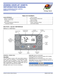
USER’S INFORMATION
MANUAL
AIR HANDLERS
MODELS: ALL
ISO 9001
Certified Quality
Management System
TABLE OF CONTENTS
CONTACT INFORMATION . . . . . . . . . . . . . . . . . . . . . . . . . . . . . . . . 1
HOW YOUR AIR HANDLER WORKS . . . . . . . . . . . . . . . . . . . . . . . . . 1
SYSTEM OPERATION . . . . . . . . . . . . . . . . . . . . . . . . . . . . . . . . . . . . 1
SETTING THE THERMOSTAT . . . . . . . . . . . . . . . . . . . . . . . . . . . . . 1
Fan Operation Selection . . . . . . . . . . . . . . . . . . . . . . . . . . . . . . . . 2
Heating Cycle . . . . . . . . . . . . . . . . . . . . . . . . . . . . . . . . . . . . . . . . 2
Cooling Cycle . . . . . . . . . . . . . . . . . . . . . . . . . . . . . . . . . . . . . . . . . 2
MANUAL CHANGE-OVER THERMOSTAT . . . . . . . . . . . . . . . . . . . 2
ELECTRONIC THERMOSTAT . . . . . . . . . . . . . . . . . . . . . . . . . . . . . 2
TO MAXIMIZE OPERATING EFFICIENCY . . . . . . . . . . . . . . . . . . . . . 2
HEATING CONSERVATION . . . . . . . . . . . . . . . . . . . . . . . . . . . . . . 2
COOLING CONSERVATION . . . . . . . . . . . . . . . . . . . . . . . . . . . . . . 2
CARE OF SYSTEM . . . . . . . . . . . . . . . . . . . . . . . . . . . . . . . . . . . . . . .3
MOTOR LUBRICATION . . . . . . . . . . . . . . . . . . . . . . . . . . . . . . . . . .3
PERIODIC INSPECTION . . . . . . . . . . . . . . . . . . . . . . . . . . . . . . . . .3
Periodic Inspection . . . . . . . . . . . . . . . . . . . . . . . . . . . . . . . . . . . . .3
AIR FILTERS . . . . . . . . . . . . . . . . . . . . . . . . . . . . . . . . . . . . . . . . . . .3
Filter Care . . . . . . . . . . . . . . . . . . . . . . . . . . . . . . . . . . . . . . . . . . . .3
Removing Internally Mounted Air Filters . . . . . . . . . . . . . . . . . . . .3
For Externally Mounted Air Filters . . . . . . . . . . . . . . . . . . . . . . . . .3
How to Clean your Filter . . . . . . . . . . . . . . . . . . . . . . . . . . . . . . . . .3
CONDENSATE DRAIN LINES . . . . . . . . . . . . . . . . . . . . . . . . . . . . .3
COIL CLEANING . . . . . . . . . . . . . . . . . . . . . . . . . . . . . . . . . . . . . . . .3
BLOWER CARE . . . . . . . . . . . . . . . . . . . . . . . . . . . . . . . . . . . . . . . .4
CONTACT INFORMATION
•
•
Go to website at www.york.com click on “contact”, then click on “contact form” and follow the instructions.
Contact us by mail:
York International
Consumer Relations
5005 York Drive
Norman, OK 73069
This high efficiency Air Handling system has been precision engineered, manufactured of high quality materials, and passed many rigorous tests and inspections to ensure years of satisfactory service. That’s
why you can rely on efficient, trouble-free operation. Your system is
fully automatic. Set the thermostat and forget it. And it’s automatically
protected from damage by voltage fluctuations or excessive heating or
cooling demands. Your Air Handler is actually two units – the indoor air
blower and the indoor refrigeration coil, part of the outdoor AC or Heat
Pump system installed with this Air Handler. You may also have an
Electric Resistance Heater kit installed in this air handler.
FIRE OR ELECTRICAL HAZARD
Failure to follow the safety warnings exactly could result in serious
injury, death or property damage.
A fire or electrical hazard may result causing property damage, personal injury or loss of life.
SECTION II: SYSTEM OPERATION
Your thermostat puts full control of the comfort level in your home at
your fingertips. DO NOT switch your thermostat rapidly “On” and “Off”
or between “Heat” to “Cool” This could damage your equipment. Always
allow at least 5 minutes between changes.
SETTING THE THERMOSTAT
Although thermostats may vary widely in appearance, they are all
designed to perform the same basic function: to control the operation of
your air conditioning or heat pump system. Regardless of size or shape,
each thermostat will feature a temperature indicator; a dial, arm, or
push button for selection of the desired temperature; a fan switch to
choose the indoor fan operation; and a comfort switch for you to select
the system mode of operation.
Only approved thermostats have been tested and are fully compatible
with this equipment. Please be aware that many different thermostats
operate on batteries or “power stealing” principals. These types of thermostats can not be supported as trouble free when used with this product.
SECTION I: HOW YOUR AIR HANDLER
WORKS
A complete operating instruction is provided by the manufacturer for
each thermostat. Familiarize yourself with its proper operation to obtain
the maximum comfort with minimum energy consumption.
If your hand is wet and you blow on it, it feels cool because some of the
moisture is evaporating and becoming a vapor. This process requires
heat. The heat is being taken from your hand, so your hand feels cool.
That’s what happens with a heat pump. During the cooling cycle, your
system will remove heat and humidity from your home and will transfer
this heat to the outdoor air. During the heating cycle, your system will
remove heat and humidity from the outdoor air and will transfer this heat
to your home. This is possible because even 0°F outdoor air contains a
great deal of heat.
If your system has been designed to allow both cooling and heating
operation, you may have either a manual change-over type, or a programmable electronic type thermostat.
Remember that your heat pump doesn’t generate much heat, it merely
transfers it from one place to another.
Manual change-over simply means that the comfort switch must be
manually positioned every time you wish to switch from the cooling to
heating or heating to cooling modes of operation.
The computerized electronic thermostat is actually a sophisticated electronic version of a manual change-over type. This thermostat includes
features which allow “set-back” temperature variations for periods of
sleep, or while you are away during the day, and means energy savings
for you. The thermostat also features a digital clock.
160619-UUM-B-0206
160619-UUM-B-0206
Fan Operation Selection
A multi-position fan switch allows you to choose the type of fan operation of the indoor fan.
AUTO - With the thermostat fan switch set to “AUTO”, the fan will run
intermittently as required for either heating or cooling. This position will
provide the lowest operating cost. If you purchased one of our thermostats, they have an Intelligent fan mode which continually circulates the
air during occupied modes or when you are at home, and can cycle the
fan during unoccupied mode or during the night while you sleep to further conserve energy.
ON - If the fan switch is set to “ON”, the indoor fan will not shut off. However, the system will still operate as required by room temperatures.
This provides continuous air filtering and more even temperature distribution throughout the house, which is especially useful in houses with
basements.
HEATING YOUR HOME: If your system includes a heating unit and the
comfort control switch is in the “HEAT” position, the system will operate
as follows: When the indoor temperature drops below the level indicated by the temperature adjustment setting, the system will start. The
heating system will operate and the indoor fan will circulate warm, filtered air. When the room temperature rises to the setting selected, the
system will shut off.
Whether heating or cooling, the fan will continue to operate if the fan
switch was set in the “ON or Intelligent” position. The “AUTO” setting on
the fan switch will allow the fan to shut off when your system does.
ELECTRONIC THERMOSTAT
Heating Cycle
The computerized electronic thermostat, when programmed, will function automatically to operate the system as follows: When the indoor
temperature rises above the higher (COOL) setting, the outdoor unit will
operate and the indoor fan will circulate cool, filtered air. When the room
temperature is lowered to the selected level, the system will shut off.
When the indoor temperature drops below the lower (HEAT) setting, the
heating system will operate, and the indoor fan will circulate the warm,
filtered air. When the indoor temperature rises to the selected setting,
the system will shut off. The indoor fan will either shut off or run continuously, depending upon your choice of fan switch setting.
With the thermostat in the heating position, and the outdoor temperature in the range of 20 to 30° or below, the outdoor unit will generally run
100%of the time.
SECTION III: TO MAXIMIZE OPERATING
EFFICIENCY
All systems can be equipped with balance point control to provide even
more efficient operation. This control will prevent the electric heater
from being energized when the outdoor air is above some predetermined temperature setting (0 to 45°F). At higher temperatures, your
system will provide all the heat your home will ever need. At lower temperatures, the auxiliary heat will be energized to keep your home comfortable.
HEATING CONSERVATION
Usually during spring and fall, when neither heating nor cooling is
required, you may want to run only the fan to ventilate, circulate, and filter the air in your home or building. Set the comfort control switch to
“OFF” and the fan switch to “ON”. Be sure to return the switches to their
original positions for normal operation.
When the outdoor air is cool and moist, frost may form on the surface of
your outdoor coil. When this frost builds to a certain point, your system
will switch to a defrost cycle. Although you may feel cooler air coming
from your registers, DO NOT adjust your thermostat. The frost will melt
quickly, and your system will return to normal operation automatically.
Cooling Cycle
Switch your thermostat to cool.Select a comfortable thermostat temperature setting, typically between 75 and 80°. Comfort sensations vary
with individuals. The lower the indoor temperature desired, the greater
will be the number of hours your unit must operate.
Set your thermostat 2 or 3°F below normal several hours before entertaining large groups during hot weather. People give off considerable
heat and moisture.
On an extremely hot day, the indoor temperature may rise 3 to 6°F
above the thermostat setting. Properly selected equipment does not
have the capacity to maintain a constant indoor temperature during the
peak load. Over-sizing your system to handle this peak load is not practical because the oversized system would operate much less efficiently
at all other conditions.
MANUAL CHANGE-OVER THERMOSTAT
COOLING YOUR HOME: With the comfort control switch in the
“COOL” position, the system will operate as follows: When the indoor
temperature rises above the level indicated by the temperature adjustment setting, the system will start. The outdoor unit will operate and the
indoor fan will circulate cool, filtered air. When the room temperature is
lowered to the setting selected, the system will shut off.
2
For the most efficient operation, keep storm windows and doors closed
all year long. They not only help insulate against heat and cold, but they
also keep out dirt, pollen, and noise.
Closing drapes at night, keeping fireplace dampers closed when not in
use, and running exhaust fans only when necessary will help you to
retain the air you have already paid to heat.
Keep lamps, televisions, or other heat producing sources away from the
thermostat. The thermostat will sense this extra heat and will not be
able to maintain the inside temperature to the desired comfort level.
COOLING CONSERVATION
To comfortably cool your home, your air conditioner must remove both
heat and humidity. Don’t turn your system off even though you will be
away all day. On a hot day, your system may have to operate between 8
to 12 hours to reduce the temperature in your home to a normal comfort
level.
Keep windows closed after sundown. While the outdoor temperature at
night may be lower than indoors, the air is generally loaded with moisture which is soaked up by furniture, carpets, and fabrics. This moisture
must be removed when you restart your system.
The hotter the outside temperature, the greater the load on your system. Therefore do not be alarmed when your system continues to run
after the sun has set on a hot day. Heat is stored in your outside walls
during the day and will continue to flow into your home for several hours
after sunset.
Use your kitchen exhaust fan when cooking. One surface burner on
“HIGH” requires one ton of cooling. Turn on your bathroom exhaust fan
while showering to remove humidity. However, exhaust fans should not
be run excessively. It would decrease efficiency by removing conditioned air.
You can also help your system in the summer by closing drapes or
blinds and by lowering awnings on windows that get direct sunlight.
Unitary Products Group
160619-UUM-B-0206
SECTION IV: CARE OF SYSTEM
IMPORTANT: The owner/user should not attempt to disassemble the
equipment nor perform periodic maintenance unless they are experienced and qualified to do so.
A periodic inspection, cleaning, lubrication, and adjustment of your heat
pump is available from your dealer. Be sure to ask him about this service.
TABLE 1:
Cabinet Size
B
C
D
Cabinet Size
B
C
D
For those who prefer to do-it-yourself, follow the instructions below to
care for your system.
MOTOR LUBRICATION
Disposable Filter Size for Built-in Filter Compartment
16”x20”x1”
20”x20”x1”
22”x20”x1”
Permanent Washable Filter Part Numbers for
Built-in Filter Compartment
S1-1PF0601
S1-1PF0602
S1-1PF0603
The motors in these Air Handlers are permanently lubricated, and do
not require periodic oiling.
PERIODIC INSPECTION
Equipment should never to operated without filters
Periodic Inspection
Removing Internally Mounted Air Filters
This Air Handler may have a filter located on bottom of the unit behind
the filter access panel.
Electric Shock and Moving Parts Hazards are present behind the
Blower & Coil access panels. Presenting risk of Personal Injury
and/or Fire or Electric Shock, potentially causing property damage,
personal injury, and/or loss of life. The only owner serviceable part
is the filter behind the bottom filter access panel
Every time the filters are changed, the following items should be visually inspected:
•
Check unit exterior to be sure it is in good condition and that there
are no obvious signs of deterioration.
• Check the drain lines to make sure there are no cracks, leaks or
blockages.
• Check the area around the unit and all registers and grilles – to
maintain good air flow.
Periodic inspection by a qualified service technician is highly recommended.
Cleaning & maintenance of the Air Handler interior and its components
must only be done by a qualified service professional.
For more information, or if you have questions about the operation of
your Air Handler, Or if you suspect your unit is malfunctioning or in need
of service or repair
•
Call a certified dealer or servicing contractor to check and/or
clean your Air Handler.
AIR FILTERS
Air filters maybe internally or externally mounted. Dirty filters greatly
restrict the flow of air and may cause damage to the moving parts. If the
filters become clogged the Electric Heaters and blower motor could
overheat resulting in a potentially dangerous situation. The filters
should be checked every month. On new construction, check the filters
every week for the first four weeks and every three weeks after that,
especially if the indoor fan is running continuously. When replacing the
filter(s) you must use filters that are the same size as those recommended in Table 1. Never operate your Air Handler without a suitable
air filter.
1.
Remove filter access panel by flipping the levers on each side of
the cabinet outward, to release the panel.
2.
Install the clean filters with “air flow” arrow in the same direction as
the air flow in your duct.
3.
Replace the panel and push levers in to secure the panel.
For Externally Mounted Air Filters
This air filter should be located in a rack attached to the casing of the
Air Handler or placed in the return air duct, or wall mounted filter grille.
Replace throw away filter(s) with the same size new filter(s).
Throw away filter(s) may be replaced with cleanable filter(s) at this time.
Cleanable filter(s) may be cleaned as described in the Manufacturer
instructions
How to Clean your Filter
Permanent type, washable, High-velocity filters may be cleaned with a
vacuum cleaner or taken away from the unit & washed with a garden
hose. Be sure to shake off excess water and allow filter to completely
dry before re-installing the filter.
CONDENSATE DRAIN LINES
Coils maybe included in the air handler or separately mounted. During
the cooling season check the condensate drain lines to be sure that
condensate is flowing from the primary drain but not from the secondary
drain. If condensate ever flows from the secondary drain the unit should
be promptly shut off and the condensate pan and drains cleaned by a
qualified sevice technican to insure a free flowing primary drain.
COIL CLEANING
If an inspection by a qualified sevice technician indicates the coil needs
to be cleaned, it should be washed with Calgon Coilclean (mix one part
Coilclean to seven parts water). Allow solution to remain on coil for 30
minutes before rinsing with clean water. Solution should not be permitted to come in contact with painted surfaces.
Filter Care
Inspect the air filter every month. If dirty, wash reusable filters with a
mild detergent per manufacturer’s recommendations. Replace disposable filters with new filters. Filters should be clean to assure maximum
efficiency and adequate air circulation. Drapes, furniture or other
obstructions blocking your supply and return air grilles will also
decrease efficiency.
Coil cleaning solutions must be diluted according to the manufacturer’s instructions. The use of undiluted coil cleaning solutions on
the coil WILL damage the coil coating.
An air filter was supplied by your dealer with you new Air Handler. A I”
filter rack compartment was built-in on your new Air Handler and may
use either a 1” disposable filter or a permanent washable filter media
per Table 1.
Unitary Products Group
3
BLOWER CARE
Even with good filters properly in place, blower wheels and motors will
become dust laden after long months of operation. The entire blower
assembly should be inspected annually. If the motor and wheel are
heavily coated with dust, they can be brushed and cleaned with a vacuum cleaner. If the blower cannot be properly cleaned without removing
it from the furnace, then this service must be performed by a qualified
service agency.
Make sure you DO NOT move the clip on weight on the
indoor fan wheel when cleaning the wheel. This weight is
used to balance the wheel. Moving the weight will cause
the fan wheel to vibrate.
TROUBLESHOOTING GUIDE
PROBLEM
No Heat
or
Cooling
CHECK
Set thermostat to proper setting.
2. Circuit breakers and fuses.
Reset circuit breakers - Replace blown fuses.
-
3. Check outdoor unit for dirty coil (Cooling).
Clean coil, see “COIL CARE” section.
2
4. Outdoor unit for snow accumulation. (Heating).
Remove loose snow only.
3
5. Indoor unit for dirty filter (Heating).
Clean or replace, see “FILTER CARE” section.
2
6. Emergency heat light status on thermostat.
Check 1 - 5, call qualified service person.
2
Light flashing = Malfunction
Condensate drain and “P” trap
-
Check 1 - 5, call qualified service person.
-
Check 1 - 5, call qualified service person with fault code.
-
Remove blockage, usually mold or fungus.
-
Subject to change without notice. Printed in U.S.A.
Copyright © by Unitary Products Group 2006. All rights reserved.
Unitary
Products
Group
FAULT CODE
1. Thermostat for proper settings.
Light on = Malfunction
Wet on Floor
or in Furnace
ACTION TO TAKE
160619-UUM-B-0206
Supersedes: 160619-UUM-A-0106
5005
York
Drive
Norman
OK
73069