1
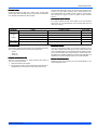
C
ER
TI
FI
ED
T O ARI
C
AIR
ER
-C
PL
NI
RY
UN I
NI N G
G W IT H
OI
IT
TA
Y
D
ON
MA N U F A C T U R
M
R-22 OUTDOOR SPLIT-SYSTEM
AIR CONDITIONER
MODELS: ERCQ SERIES
2 TO 4 TONS
AS
O
USER’S INFORMATION
MANUAL
R
IF
RI
F
U I P M EN T
I CA
T
O
EQ
E
C
RT
A
T IO
NS
I ON S E C
10
S T A NDA R D 2
Certification applies only
when the complete
system is listed
with ARI.
LISTED
ISO 9001
Certified Quality
Management System
TABLE OF CONTENTS
CONTACT INFORMATION . . . . . . . . . . . . . . . . . . . . . . . . . . . . . . . 1
HOW YOUR AIR CONDITIONER WORKS . . . . . . . . . . . . . . . . . . . . . 1
SYSTEM OPERATION . . . . . . . . . . . . . . . . . . . . . . . . . . . . . . . . . . . . 1
SETTING THE THERMOSTAT . . . . . . . . . . . . . . . . . . . . . . . . . . . . 1
Fan Operation Selection . . . . . . . . . . . . . . . . . . . . . . . . . . . . . . . . 2
MANUAL CHANGE-OVER THERMOSTAT . . . . . . . . . . . . . . . . . . 2
ELECTRONIC THERMOSTAT . . . . . . . . . . . . . . . . . . . . . . . . . . . . 2
TO MAXIMIZE OPERATING EFFICIENCY . . . . . . . . . . . . . . . . . . . . . 2
HEATING CONSERVATION . . . . . . . . . . . . . . . . . . . . . . . . . . . . . . 2
COOLING CONSERVATION . . . . . . . . . . . . . . . . . . . . . . . . . . . . . 2
CARE OF SYSTEM . . . . . . . . . . . . . . . . . . . . . . . . . . . . . . . . . . . . .2
COIL CARE . . . . . . . . . . . . . . . . . . . . . . . . . . . . . . . . . . . . . . . . . . .2
CARE OF FAN MOTORS . . . . . . . . . . . . . . . . . . . . . . . . . . . . . . . .2
FILTER CARE . . . . . . . . . . . . . . . . . . . . . . . . . . . . . . . . . . . . . . . . .3
OUTDOOR UNIT FINISH . . . . . . . . . . . . . . . . . . . . . . . . . . . . . . . .3
CLEARANCES . . . . . . . . . . . . . . . . . . . . . . . . . . . . . . . . . . . . . . . . .3
POWER INTERRUPTION . . . . . . . . . . . . . . . . . . . . . . . . . . . . . . . .3
SERVICE CALLS . . . . . . . . . . . . . . . . . . . . . . . . . . . . . . . . . . . . . . .3
PARTS INFORMATION . . . . . . . . . . . . . . . . . . . . . . . . . . . . . . . . . .3
LIMITED WARRANTY . . . . . . . . . . . . . . . . . . . . . . . . . . . . . . . . . . . . .4
CONTACT INFORMATION FOR USA
CONTACT INFORMATION FOR CANADA
•
Contact us by mail:
DISTRIBUTED BY:
StyleCrest
801 W. 37th Street
Building #1
Wichita, Ks 67219
•
MANUFACTURED BY:
York International
5005 York Drive
Norman, OK 73069
•
Go to website at www.york.com click on “contact”, then click on
“contact form” and follow the instructions.
Contact us by mail:
York International
Consumer Relations
5005 York Drive
Norman, OK 73069
This high efficiency air conditioning system has been precision engineered, manufactured of high quality materials, and passed many rigorous tests and inspections to ensure years of satisfactory service. That’s
why you can rely on efficient, trouble-free operation.
Only approved thermostats have been tested and are fully compatible
with this equipment. Please be aware that many different thermostats
operate on batteries or “power stealing” principals. These types of thermostats can not be supported as trouble free when used with this product.
Your system is fully automatic. Set the thermostat and forget it. And it’s
automatically protected from damage by voltage fluctuations or excessive heating or cooling demands.
A complete operating instruction is provided by the manufacturer for
each thermostat. Familiarize yourself with its proper operation to obtain
the maximum comfort with minimum energy consumption.
Your split system air conditioner consists of two units - one installed outdoors and one installed indoors. The indoor unit may be installed in a
basement, attic, or crawl space.
If your system has been designed to allow both cooling and heating
operation, you may have either a manual change-over type, or a programmable electronic type thermostat.
HOW YOUR AIR CONDITIONER WORKS
Manual change-over simply means that the comfort switch must be
manually positioned every time you wish to switch from the cooling to
heating or heating to cooling modes of operation.
If your hand is wet and you blow on it, it feels cool because some of the
moisture is evaporating and becoming a vapor. This process requires
heat. The heat is being taken from your hand, so your hand feels cool.
That’s what happens with an air conditioner. During the cooling cycle,
your system will remove heat and humidity from your home and will
transfer this heat to the outdoor air.
The computerized electronic thermostat is actually a sophisticated electronic version of a manual change-over type. This thermostat includes
features which allow “set-back” temperature variations for periods of
sleep, or while you are away during the day, and means energy savings
for you. The thermostat also features a digital clock.
SYSTEM OPERATION
Your thermostat puts full control of the comfort level in your home at
your fingertips. DO NOT switch your thermostat rapidly “On” and “Off”
or between “Heat” to “Cool” This could damage your equipment. Always
allow at least 5 minutes between changes.
SETTING THE THERMOSTAT
Although thermostats may vary widely in appearance, they are all
designed to perform the same basic function: to control the operation of
your air conditioning or heat pump system. Regardless of size or shape,
each thermostat will feature a temperature indicator; a dial, arm, or
push button for selection of the desired temperature; a fan switch to
choose the indoor fan operation; and a comfort switch for you to select
the system mode of operation.
The main power to the system must be kept “ON” at all times to
prevent damage to the outdoor unit compressor. If necessary,
the thermostat control switch should be used to turn the system
“OFF”. Should the main power be disconnected or interrupted
for 8 hours or longer, DO NOT attempt to start the system for 8
hours after the power has been restored to the outdoor unit.
174567-UUM-D-0107
174567-UUM-D-0107
Fan Operation Selection
A multi-position fan switch allows you to choose the type of fan operation of the indoor fan.
AUTO - With the thermostat fan switch set to “AUTO”, the fan will run
intermittently as required for either heating or cooling. This position will
provide the lowest operating cost.
ON - If the fan switch is set to “ON”, the indoor fan will not shut off. However, the system will still operate as required by room temperatures.
This provides continuous air filtering and more even temperature distribution throughout the house, which is especially useful in houses with
basements.
Usually during spring and fall, when neither heating nor cooling is
required, you may want to run only the fan to ventilate, circulate, and filter the air in your home or building. Set the comfort control switch to
“OFF” and the fan switch to “ON”. Be sure to return the switches to their
original positions for normal operation.
MANUAL CHANGE-OVER THERMOSTAT
COOLING YOUR HOME: With the comfort control switch in the
“COOL” position, the system will operate as follows: When the indoor
temperature rises above the level indicated by the temperature adjustment setting, the system will start. The outdoor unit will operate and the
indoor fan will circulate cool, filtered air. When the room temperature is
lowered to the setting selected, the system will shut off.
HEATING YOUR HOME: If your system includes a heating unit and the
comfort control switch is in the “HEAT” position, the system will operate
as follows: When the indoor temperature drops below the level indicated by the temperature adjustment setting, the system will start. The
heating system will operate and the indoor fan will circulate warm, filtered air. When the room temperature rises to the setting selected, the
system will shut off.
Whether heating or cooling, the fan will continue to operate if the fan
switch was set in the “ON or Intelligent” position. The “AUTO” setting on
the fan switch will allow the fan to shut off when your system does.
ELECTRONIC THERMOSTAT
The computerized electronic thermostat, when programmed, will function automatically to operate the system as follows: When the indoor
temperature rises above the higher (COOL) setting, the outdoor unit will
operate and the indoor fan will circulate cool, filtered air. When the room
temperature is lowered to the selected level, the system will shut off.
When the indoor temperature drops below the lower (HEAT) setting, the
heating system will operate, and the indoor fan will circulate the warm,
filtered air. When the indoor temperature rises to the selected setting,
the system will shut off. The indoor fan will either shut off or run continuously, depending upon your choice of fan switch setting.
TO MAXIMIZE OPERATING EFFICIENCY
HEATING CONSERVATION
For the most efficient operation, keep storm windows and doors closed
all year long. They not only help insulate against heat and cold, but they
also keep out dirt, pollen, and noise.
Closing drapes at night, keeping fireplace dampers closed when not in
use, and running exhaust fans only when necessary will help you to
retain the air you have already paid to heat.
Keep lamps, televisions, or other heat producing sources away from the
thermostat. The thermostat will sense this extra heat and will not be
able to maintain the inside temperature to the desired comfort level.
COOLING CONSERVATION
To comfortably cool your home, your air conditioner must remove both
heat and humidity. Don’t turn your system off even though you will be
away all day. On a hot day, your system may have to operate between 8
2
to 12 hours to reduce the temperature in your home to a normal comfort
level.
Keep windows closed after sundown. While the outdoor temperature at
night may be lower than indoors, the air is generally loaded with moisture which is soaked up by furniture, carpets, and fabrics. This moisture
must be removed when you restart your system.
The hotter the outside temperature, the greater the load on your system. Therefore do not be alarmed when your system continues to run
after the sun has set on a hot day. Heat is stored in your outside walls
during the day and will continue to flow into your home for several hours
after sunset.
Use your kitchen exhaust fan when cooking. One surface burner on
“HIGH” requires one ton of cooling. Turn on your bathroom exhaust fan
while showering to remove humidity. However, exhaust fans should not
be run excessively. It would decrease efficiency by removing conditioned air.
You can also help your system in the summer by closing drapes or
blinds and by lowering awnings on windows that get direct sunlight.
CARE OF SYSTEM
IMPORTANT: The owner/user should not attempt to disassemble the
equipment nor perform periodic maintenance unless they are experienced and qualified to do so.
A periodic inspection, cleaning, lubrication, and adjustment of your outdoor unit is available from your dealer. Be sure to ask him about this
service.
For those who prefer to do-it-yourself, follow the instructions below to
care for your system.
COIL CARE
Keep the outdoor unit free of loose snow, foliage, grass clippings,
leaves, paper, and any other material which could restrict the proper air
flow in and out of the unit. The coil may be vacuumed to remove any
debris from between the fins. However, don’t knock ice off the outdoor
unit’s coil surface following an ice or severe snowstorm. The blows
could mash the coil fins shut (blocking air passage), or break the refrigerant tubing allowing the refrigerant to escape.
If the coil becomes excessively dirty, turn the main disconnect switch to
“OFF” and wash the coil with your garden hose. Avoid getting water into
the fan motor and control box. Flush dirt from base pan after cleaning
the coil.
CARE OF FAN MOTORS
Some fan motors are provided with lubrication ports. Inspect your
indoor and outdoor units to determine whether or not lubrication ports
are provided.
The fan motor is shipped with an oil supply which will last for several
years under normal operating conditions. After this time, each motor
bearing should be oiled with 10-15 drops (approximately 1/4 teaspoon)
of SAE 20 non-detergent electric motor oil or automobile oil. DO NOT
use definite purpose oils such as sewing machine, cleaning, rust preventative, cutting, household, etc.
SCHEDULE FOR RELUBRICATION
Environment
Running Hours
Per Day
Normal
Dirty
0-8
Every 5 Yrs.
Every 4 Yrs.
9-16
Every 4 Yrs.
Every 3 Yrs.
17-24
Every 3 Yrs.
Every 2 Yrs.
Do not over oil
If your system is an add-on type, (installed in conjunction with a standard furnace) inspect your furnace blower motor and care for it in the
same way.
Unitary Products Group
174567-UUM-D-0107
FILTER CARE
Inspect the air filter(s) at least once a month. If they are dirty, wash
reusable filters with a mild detergent per manufacturer’s recommendations. Replace disposable filters with new filters.
Install the clean filters with “air flow” arrow in the same direction as the
air flow in your duct. Filters should be clean to assure maximum efficiency and adequate air circulation. Drapes, furniture or other obstructions blocking your supply and return air grilles will also decrease
efficiency.
OUTDOOR UNIT FINISH
If you wish to maintain the finish of the outdoor unit, it can be polished
with car wax. It is recommended the unit be cleaned with soap and
water prior to waxing.
TROUBLESHOOTING GUIDE
PROBLEM
CHECK
1. Thermostat for proper settings.
No Heat
or
Cooling
Wet on Floor
or in Furnace
ACTION TO TAKE
Set thermostat to proper setting.
FAULT CODE
-
2. Circuit breakers and fuses.
Reset circuit breakers - Replace blown fuses.
-
3. Check outdoor unit for dirty coil (Cooling).
Clean coil, see “COIL CARE” section.
2
4. Indoor unit for dirty filter (Heating).
Clean or replace, see “FILTER CARE” section.
2
Condensate drain and “P” trap
Remove blockage, usually mold or fungus.
-
CLEARANCES
SERVICE CALLS
The minimum clearances shown below must be maintained should any
patio or yard improvements be done around the outdoor unit.
There are a few instances where you can avoid unnecessary service
calls. (See Troubleshooting Guide above). Some models provide fault
codes. The flashing light on the system thermostat is capable of providing you with time and money saving information. The fault code numbers listed can be handled by taking the corrective action indicated. Call
qualified service person if displaying fault code numbers not listed.
•
•
•
Top 48”
Sides 12”
Access 24”
POWER INTERRUPTION
When ice, snow, wind storms, etc. disrupt electrical power supply to
your house, proceed as follows:
1.
2.
Switch thermostat to OFF position.
Do not switch to cooling or auto until electrical power has been reestablished for 8 hours if the power was off more than 8 hours.
Unitary Products Group
PARTS INFORMATION
Replacement parts are available from local contractor/dealers or the
nearest distribution center.
3
Limited Warranty
Manufactured Housing Quick Connect Air Conditioners
UPG warrants this product to be free from defects in factory workmanship and material under normal use and service and will replace parts that prove to have
such defects according to the terms outlined below.
Model
Compressor
Parts Coverage
Labor and Trip Coverage*
ERCQ
5 years
1 years
1 years
*Thermostat labor coverage for 30 days only, no trip allowance.
The warranty period for any replacement compressor or part provided here under shall not extend beyond the warranty period stated above. The compressor
warranty is on a parts only basis the third through fifth year no labor, freight or other service charges are allowed.
The warranty period will begin on the purchase date of the residence when the product is installed as original equipment, or the installation date when installed
in a residence previously purchased by the consumer. Return the Warranty Registration Card to UPG promptly after product installation or purchase for your
benefit and protection. The warranty period will begin upon product shipment from UPG in the absence of a recorded Warranty Registration Card.
This warranty applies to the original consumer/purchaser and any subsequent purchaser. The warranty does not apply if the air conditioner is removed from the
original residence, or if the residence has been moved from the original location where the air conditioner was placed in service.
This warranty applies only to products installed: (1) in the United States of America or Canada; (2) in accordance with UPG recommendations and specifications outlined in the Installation Manual provided with the product; (3) in accordance with all national, state/provincial, and local codes; and (4) in the original
residence.
Exclusions
1.
Shipping/freight, or material charges.
2.
Damages resulting from transportation, mishandling, improper application, installation or servicing.
3.
Damages resulting from accident, abuse, fire, flood, or other acts of nature.
4.
Use of the product in a corrosive atmosphere.
5.
Alteration, tampering, defacing or removing the product serial number will serve to void the warranty.
6.
Damages resulting from inadequacy or interruption of electrical service, improper energy supply, blown fuses, improper wiring external to the
unit or other like damages.
7.
Damages resulting from the use of components not approved by UPG.
8.
This warranty does not cover consequential damages, incidental damages or incidental expenses including damages to property.
9.
Damages caused by failure to perform normal or routine maintenance as set out in the operation and service instructions.
10. Cleaning, replacement of filters, or any other routine maintenance as set out in the User’s Information, Maintenance and Service Manual.
11. Replacement or cleaning of nozzles or orifices.
12. Fuses either internal or external to the product.
13. Excessive fuel or electricity consumption.
THIS WARRANTY IS IN LIEU OF ALL OTHER WARRANTIES, EXPRESSED OR IMPLIED, INCLUDING THE IMPLIED WARRANTIES OF MERCHANTABILITY AND FITNESS FOR A PARTICULAR PURPOSE. SOME STATES DO NOT ALLOW THE DISCLAIMER OF IMPLIED WARRANTY, SO THAT THE ABOVE
DISCLAIMER MAY NOT APPLY TO YOU.
SOME STATES ALLOW ONLY A PARTIAL LIMITATION ON IMPLIED WARRANTIES, OR LIMIT THE DURATION OF IMPLIED WARRANTIES TO THE
DURATION OF THE EXPRESS WARRANTY. IN SUCH STATES, THE DURATION OF IMPLIED WARRANTIES IS HEREBY EXPRESSLY LIMITED TO THE
DURATION OF THE EXPRESS WARRANTY ON THE FACE HEREOF. IN NO EVENT, WHETHER AS A RESULT OF BREACH OF WARRANTY OR CONTRACT TORT (INCLUDING NEGLIGENCE) STRICT LIABILITY OR OTHERWISE, SHALL UPG BE LIABLE FOR SPECIAL, INCIDENTAL, OR CONSEQUENTIAL DAMAGES, INCLUDING BUT NOT LIMITED TO LOSS OF USE OF THE EQUIPMENT OR ASSOCIATED EQUIPMENT, LOST REVENUES OR
PROFITS, COST OF SUBSTITUTE EQUIPMENT. THIS WARRANTY DOES NOT COVER CONSEQUENTIAL DAMAGES. THE ABOVE LIMITATIONS
SHALL INURE TO THE BENEFIT OF UPG SUPPLIERS AND SUBCONTRACTORS. THE ABOVE LIMITATION ON CONSEQUENTIAL DAMAGES SHALL
NOT APPLY TO INJURIES TO PERSONS IN THE CASE OF CONSUMER GOODS.
SOME STATES DO NOT ALLOW THE EXCLUSION OR LIMITATION OF LIABILITY FOR CONSEQUENTIAL OR INCIDENTAL DAMAGES, OR FOR STRICT
LIABILITY IN TORT, SO THAT THE ABOVE EXCLUSIONS AND LIMITATIONS MAY NOT APPLY TO YOU. UPG DOES NOT ASSUME, OR AUTHORIZE
ANY PERSON TO ASSUME FOR UPG ANY LIABILITY FOR THE SALE OF THIS PRODUCT. THIS WARRANTY GIVES YOU SPECIFIC LEGAL RIGHTS.
YOU MAY ALSO HAVE OTHER RIGHTS WHICH VARY FROM STATE TO STATE.
TO OBTAIN WARRANTY SERVICE
Consult the Authorized Service Center list packed with the furnace installed in the manufactured home or contact your installing or servicing dealer.
Or, look in the Yellow Pages of the telephone book under Mobile Homes-or Manufactured Housing-Repair and Service for the name and telephone number of
the nearest authorized manufactured housing service center. If local authorized service cannot be obtained, or you are unable to contact your installing dealer,
contact the authorized distributor in your area. If there is no distributor in your area, and you cannot obtain proper service under the terms of the warranty,
please write: Unitary Products Group (UPG) Customer Relations Department, PO Box 19014, Wichita, KS 67204-9014.
Subject to change without notice. Printed in U.S.A.
Copyright © by Unitary Products Group 2007. All rights reserved.
Unitary
Products
Group
174567-UUM-D-0107
Supersedes: 174567-UUM-C-0506
5005
York
Drive
Norman
OK
73069