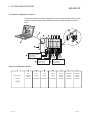
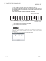
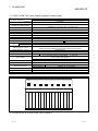
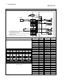
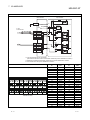
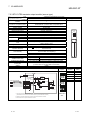
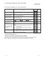
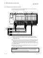
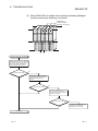
1
MITSUBISHI ELECTRIC
MELSEC ST Series
Programmable Logic Controllers
User's Manual
Profibus/DP
Base, Power and I/O Modules
Art. no.: 157180
01 09 2008
SH(NA)-080456
Version H
MITSUBISHI ELECTRIC
INDUSTRIAL AUTOMATION
SAFETY PRECAUTIONS
(Read these precautions before using.)
When using Mitsubishi equipment, thoroughly read this manual and the associated manuals introduced in
this manual. Also pay careful attention to safety and handle the module properly.
The precautions given in this manual are concerned with this product. Refer to the user's manual of the
network system to use for a description of the network system safety precautions.
These SAFETY PRECAUTIONS classify the safety precautions into two categories: "DANGER" and
"CAUTION".
DANGER
Indicates that incorrect handling may cause hazardous conditions,
resulting in death or severe injury.
! CAUTION
Indicates that incorrect handling may cause hazardous conditions,
resulting in medium or slight personal injury or physical damage.
!
Depending on circumstances, procedures indicated by ! CAUTION may also be linked to serious
results.
In any case, it is important to follow the directions for usage.
Store this manual in a safe place so that you can take it out and read it whenever necessary. Always
forward it to the end user.
[DESIGN PRECAUTIONS]
!
DANGER
Create an interlock circuit on the program so that the system will operate safety based on the
communication status information. Failure to so may cause an accident due to an erroneous
output or malfunction.
When an error occurs, all outputs are turned OFF in the MELSEC-ST system (at default).
However, I/O operations of the head module and respective slice modules can be selected for
the errors described below.
Select the status for each module for the entire system safety.
(1) Communication error (Head Module User’s Manual)
(2) Slice module error
The output status for the case of an error can be set to Clear, Hold or Preset with a
command parameter of each slice module. (For setting availability, refer to the manual for
each slice module.)
Since the parameter is defaulted to Clear, outputs will be turned off if an error occurs.
This parameter setting can be changed to Hold or Preset when the system safety is more
ensured by holding or presetting the output.
A-1
A-1
[DESIGN PRECAUTIONS]
!
DANGER
Create an external fail safe circuit that will ensure the MELSEC-ST system operates safely,
even when the external power supply or the system fails.
Accident may occur due to output error or malfunctioning.
(1) The status of output changes depending on the setting of various functions that control the
output. Take sufficient caution when setting for those functions.
(2) Output may be kept ON or OFF due to malfunctions of an output element or its internal
circuits.
For signals which may cause a serious accident, configure an external monitoring.
!
CAUTION
Make sure to initialize the network system after changing parameters of the MELSEC-ST
system or the network system. If unchanged data remain in the network system, this may cause
malfunctions.
Do not install the control wires or communication cables together with the main circuit or power
wires. Keep a distance of 100 mm (3.94 inch) or more between them. Not doing so could result
in malfunctions due to noise.
[INSTALLATION PRECAUTIONS]
!
CAUTION
Use the MELSEC-ST system in the general environment specified in the MELSEC-ST system
users manual. Using this MELSEC-ST system in an environment outside the range of the
general specifications could result in electric shock, fire, erroneous operation, and damage to or
deterioration of the product.
Mount the head module and base module on the DIN rail securely (one rail for one module)
referring to the MELSEC-ST system users manual and then fix them with end brackets.
Incorrect mounting may result in a drop of the module, short circuits or malfunctions.
Secure the module with several end brackets when using it in an environment of frequent
vibration. Tighten the screws of the end brackets within the specified torque range.
Undertightening can cause a drop, short circuit or malfunction. Overtightening can cause a
drop, short circuit or malfunction due to damage to the screw or module.
A-2
A-2
[INSTALLATION PRECAUTIONS]
!
CAUTION
Make sure to externally shut off all phases of the power supply for the whole system before
mounting or removing a module. Failure to do so may damage the module.
(1) Online replacement of the power distribution module and/or the base module is not
available. When replacing either of the modules, shut off all phases of the external power
supply.
Failure to do so may result in damage to all devices of the MELSEC-ST system.
(2) The I/O modules and the intelligent function modules can be replaced online.
Since online replacement procedures differ depending on the module type, be sure to make
replacement as instructed.
For details, refer to the chapter describing the online module change in the user’s manual of
the head module (for the I/O module) or the corresponding intelligent function module.
Do not directly touch the module's conductive parts or electronic components. Doing so may
cause malfunctions or failure of the module.
Make sure to securely connect each cable connector. Failure to do so may cause malfunctions
due to poor contact.
DIN rail must be conductive; make sure to ground it prior to use. Failure to do so may cause
electric shocks or malfunctions. Undertightening can cause a drop, short circuit or malfunction.
Overtightening can cause a drop, short circuit or malfunction due to damage to the screw or
module.
[WIRING PRECAUTIONS]
!
DANGER
Completely turn off the external power supply when installing or placing wiring. Not completely
turning off all power could result in electric shock or damage to the product.
!
CAUTION
Make sure to ground the control panel where the MELSEC-ST system is installed in the manner
specified for the MELSEC-ST system. Failure to do so may cause electric shocks or
malfunctions.
Check the rated voltage and the terminal layout and wire the system correctly. Connecting an
inappropriate power supply or incorrect wiring could result in fire or damage.
Tighten the terminal screws within the specified torque. If the terminal screws are loose, it could
result in short circuits, fire, or erroneous operation. Overtightening may cause damages to the
screws and/or the module, resulting in short circuits or malfunction.
A-3
A-3
[WIRING PRECAUTIONS]
!
CAUTION
Prevent foreign matter such as chips or wiring debris from entering the module. Failure to do so
may cause fires, damage or erroneous operation.
When connecting the communication and power supply cables to the module, always run them
in conduits or clamp them. Not doing so can damage the module and cables by pulling a
dangling cable accidentally or can cause a malfunction due to a cable connection fault.
When disconnecting the communication and power supply cables from the module, do not hold
and pull the cable part. Disconnect the cables after loosening the screws in the portions
connected to the module. Pulling the cables connected to the module can damage the module
and cables or can cause a malfunction due to a cable connection fault.
[STARTUP AND MAINTENANCE PRECAUTIONS]
!
DANGER
Do not touch the terminals while power is on.
Doing so could cause shock or erroneous operation.
Make sure to shut off all phases of the external power supply for the system before cleaning the
module or tightening screws.
Not doing so can cause the module to fail or malfunction.
!
CAUTION
Do not disassemble or modify the modules.
Doing so could cause failure, erroneous operation, injury or fire.
Do not drop or give a strong impact to the module since its case is made of resin. Doing so can
damage the module.
Make sure to shut off all phases of the external power supply for the system before mounting/
removing the module onto/from the control panel. Not doing so can cause the module to fail or
malfunction.
The number of terminal block installations/removals is limited to 50 times or less.
(Compliant with JIS B 3502)
Exceeding the count of 50 may cause malfunctions.
A-4
A-4
[STARTUP AND MAINTENANCE PRECAUTIONS]
!
CAUTION
Before handling the module, make sure to touch a grounded metal object to discharge the static
electricity from the human body.
Failure to do say cause a failure or malfunctions of the module.
When using any radio communication device such as a cellular phone, keep a distance of at
least 25cm (9.85 inch) away from the MELSEC-ST system.
Not doing so can cause a malfunction.
[DISPOSAL PRECAUTIONS]
!
CAUTION
When disposing of this product, treat it as industrial waste.
A-5
A-5
REVISIONS
The manual number is given on the bottom left of the back cover.
Print Date
Dec., 2003
Aug., 2004
Manual Number
Revision
SH(NA)-080456ENG-A First edition
SH(NA)-080456ENG-B Partial addition
Contents, Section 3.3, 5.1, 10.2
Apr., 2005
SH(NA)-080456ENG-C
Partial addition
SAFETY PRECAUTIONS, About Manuals, Section 1, 1.1, 2, 3.1,
3.2, 3.3, 3.4, 5.1, 5.2.1, 8.3, 9.2, 10.1, 10.4.1, 12.2.1,
Appendix 1.3, INDEX
Nov., 2005
SH(NA)-080456ENG-D
Additional functions
ST1Y2-TE8
Partial addition
Contents, Chapter 2, Section 3.3, 3.4, 7.3, Appendix 1.2
Addition
Section 7.2.3
Section No. Change
Section 7.2.3 to 5
Jun., 2006
SH(NA)-080456ENG-E
Section 7.2.4 to 6
Partial addition
Appendix 1.1, 1.2, 1.3
Aug., 2006
SH(NA)-080456ENG-F
Partial addition
Section 3.3, 3.4, 7.2.1, 7.2.2, 7.2.3, 8.3, 12.3.3
Apr., 2008
SH(NA)-080456ENG-G
Additional functions
ST1H-BT, ST1DA1-1-F01, ST1DA2-V-F01
Partial addition
SAFETY PRECAUTIONS, CONTENTS, About Manuals, How to
Read Manual, About the Generic Terms and Abbreviations, Term
definition, Chapter 1, Section 1.1, Chapter 2, Section 3.2, 3.3, 3.4,
4.1, 5.1, 5.2.1, 5.3.1, 7.1, 7.1.1, 7.1.2, 7.1.3, 7.2, 7.2.1, 7.2.2, 7.2.3,
7.2.4, 7.2.5, 7.2.6, 7.3, 7.4, 8.1, 8.3, Chapter 9, Section 9.2, 10.1,
10.3, 10.4.2, 10.5, 11.1.3, 11.2.3, 12.1.1, 12.4
Addition
Section 3.1.1, 3.1.2, 9.1, Appendix 2
Section No. Change
Section 9.1
Section 9.2
Appendix 2
Appendix 3
A-6
Section 9.2.1
Section 9.2.2
Appendix 3
Appendix 3.2
A-6
The manual number is given on the bottom left of the back cover.
Print Date
Nov., 2008
Manual Number
SH(NA)-080456ENG-H
Revision
Partial addition
Contents, Section 4.1, 7.3
Addition
Section 7.3.1, 7.3.2, 7.3.3
Japanese Manual Version SH-080455-I
This manual confers no industrial property rights or any rights of any other kind, nor does it confer any patent
licenses. Mitsubishi Electric Corporation cannot be held responsible for any problems involving industrial property
rights which may occur as a result of using the contents noted in this manual.
© 2003 MITSUBISHI ELECTRIC CORPORATION
A-7
A-7
INTRODUCTION
Thank you for choosing the MELSEC-ST series.
Before using the module, please read this manual carefully to fully understand the functions and
performance of the MELSEC-ST series and use it correctly.
CONTENTS
SAFETY PRECAUTIONS..............................................................................................................................A- 1
REVISIONS ....................................................................................................................................................A- 6
CONTENTS....................................................................................................................................................A- 8
About Manuals ...............................................................................................................................................A-11
How to Read Manual (FOR CC-LINK) ..........................................................................................................A-13
How to Read Manual (FOR PROFIBUS-DP)................................................................................................A-15
Generic Terms and Abbreviations .................................................................................................................A-17
Term definition for CC-Link ............................................................................................................................A-18
Term definition for PROFIBUS-DP ................................................................................................................A-20
1 OVERVIEW
1- 1 to 1- 3
1.1 Features .................................................................................................................................................... 1- 2
2 HOW TO IDENTIFY MODULE NAMES
2- 1 to 2- 2
3 SYSTEM CONFIGURATION
3- 1 to 3-15
3.1 System Configuration............................................................................................................................... 33.1.1 CC-Link.............................................................................................................................................. 33.1.2 PROFIBUS-DP.................................................................................................................................. 33.2 System Configuration Outline.................................................................................................................. 33.3 Device Configuration................................................................................................................................ 33.4 Precautions for System Configuration..................................................................................................... 34 GENERAL SPECIFICATIONS
1
1
2
3
5
7
4- 1 to 4- 2
4.1 General Specifications ............................................................................................................................. 4- 1
4.2 Other System Specifications.................................................................................................................... 4- 2
5 POWER DISTRIBUTION MODULES
5- 1 to 5-12
5.1 Specifications ........................................................................................................................................... 5- 1
5.2 Selection of Power Distribution Modules................................................................................................. 5- 3
5.2.1 Current consumption calculation ...................................................................................................... 5- 3
5.3 Part Names .............................................................................................................................................. 5-11
5.3.1 Operating Status LEDs ..................................................................................................................... 5-12
6 BASE MODULE
6- 1 to 6- 3
6.1 Base Module Specifications..................................................................................................................... 6- 1
6.2 Base module selection............................................................................................................................. 6- 2
A-8
A-8
6.3 Part Names .............................................................................................................................................. 6- 3
7 I/O MODULES
7- 1 to 7-23
7.1 Input Module Specifications..................................................................................................................... 7- 1
7.1.1 ST1X2-DE1 DC input module (negative common type) .................................................................. 7- 1
7.1.2 ST1X4-DE1 DC input module (negative common type) .................................................................. 7- 2
7.1.3 ST1X16-DE1 DC input module (negative common type)................................................................ 7- 3
7.2 Output Module Specifications.................................................................................................................. 7- 5
7.2.1 ST1Y2-TE2 transistor output module (source type) ........................................................................ 7- 5
7.2.2 ST1Y16-TE2 transistor output module (source type) ...................................................................... 7- 6
7.2.3 ST1Y2-TE8 transistor output module (source type) ........................................................................ 7- 8
7.2.4 ST1Y2-TPE3 transistor output module (source type) ...................................................................... 7- 9
7.2.5 ST1Y16-TPE3 transistor output module with protective functions (source type) ........................... 7-10
7.2.6 ST1Y2-R2 Contact Output Module................................................................................................... 7-12
7.3 Precautions for Use.................................................................................................................................. 7-13
7.3.1 Input module...................................................................................................................................... 7-13
7.3.2 Output module................................................................................................................................... 7-13
7.3.3 Module with protection function ........................................................................................................ 7-21
7.4 Part Names .............................................................................................................................................. 7-22
8 ACCESSORIES
8- 1 to 8- 2
8.1 End Plate, End brackets .......................................................................................................................... 8- 1
8.2 Markers..................................................................................................................................................... 8- 1
8.3 Coding Elements...................................................................................................................................... 8- 2
9 FUNCTIONS AVAILABLE BY USE OF SOFTWARE
9- 1 to 9- 7
9.1 For CC-Link .............................................................................................................................................. 99.1.1 Functions available by use of GX Configurator-ST.......................................................................... 99.2 For PROFIBUS-DP .................................................................................................................................. 99.2.1 Functions Available by Use of Configuration Software.................................................................... 99.2.2 Functions Available by Use of GX Configurator-ST......................................................................... 910 MOUNTING AND INSTALLATION
1
1
4
4
5
10- 1 to 10-22
10.1 Handling Precautions........................................................................................................................... 10- 1
10.2 Mounting the Modules.......................................................................................................................... 10- 4
10.3 Removing the Modules ........................................................................................................................ 10-11
10.4 Wiring.................................................................................................................................................... 10-14
10.4.1 Wiring precautions ........................................................................................................................ 10-14
10.4.2 Wiring the power distribution modules ......................................................................................... 10-18
10.5 Calculating Heat Generation by unit.................................................................................................... 10-19
11 EMC AND LOW VOLTAGE DIRECTIVE
11- 1 to 11- 9
11.1 Requirements for Compliance with EMC Directive............................................................................. 1111.1.1 EMC Directive standards .............................................................................................................. 1111.1.2 Instructions for installing into control panel .................................................................................. 1111.1.3 Cables............................................................................................................................................ 11A-9
A-9
1
1
2
3
11.1.4 External power supply module...................................................................................................... 1111.1.5 Others ............................................................................................................................................ 1111.2 Requirement for Compliance with the Low Voltage Directive ............................................................ 1111.2.1 Standard applied for MELSEC-ST series..................................................................................... 1111.2.2 MELSEC-ST series selection ....................................................................................................... 1111.2.3 Power supply................................................................................................................................. 1111.2.4 Control box .................................................................................................................................... 1111.2.5 Grounding...................................................................................................................................... 1111.2.6 External wiring............................................................................................................................... 1112 TROUBLESHOOTING
5
6
7
7
7
8
8
9
9
12- 1 to 12-16
12.1 MELSEC-ST System Troubleshooting................................................................................................ 12- 1
12.1.1 MELSEC-ST system checkup ...................................................................................................... 12- 2
12.1.2 When RUN LED of slice module is off.......................................................................................... 12- 3
12.1.3 When RUN LED of slice module (excluding intelligent function module) is flickering
(1s interval).................................................................................................................................... 12- 4
12.2 Power Distribution Module Troubleshooting ....................................................................................... 12- 6
12.2.1 When RUN LED is flickering or off (Common to bus refreshing module and power
feeding module)............................................................................................................................. 12- 6
12.2.2 When ERR. LED is on or flickering............................................................................................... 12- 6
12.3 I/O Module Troubleshooting ................................................................................................................ 12- 8
12.3.1 When RUN LED is flickering or off ............................................................................................... 12- 8
12.3.2 When ERR. LED is on or flickering............................................................................................... 12- 8
12.3.3 Troubleshooting examples............................................................................................................ 12-12
12.4 Error Code List ..................................................................................................................................... 12-15
APPENDICES
App- 1 to App-20
Appendix 1 Outer Dimension Drawings ....................................................................................................App- 1
Appendix 1.1 Power distribution modules .............................................................................................App- 1
Appendix 1.2 I/O modules......................................................................................................................App- 3
Appendix 1.3 Base modules ..................................................................................................................App- 5
Appendix 1.4 Accessory.........................................................................................................................App- 8
Appendix 2 CC-Link ...................................................................................................................................App- 9
Appendix 2.1 I/O data.............................................................................................................................App- 9
Appendix 2.1.1 Power distribution modules ......................................................................................App- 9
Appendix 2.1.2 Input modules ...........................................................................................................App- 9
Appendix 2.1.3 Output modules ........................................................................................................App-10
Appendix 2.2 I/O points sheet................................................................................................................App-11
Appendix 3 PROFIBUS-DP .......................................................................................................................App-12
Appendix 3.1 Input/Output Data.............................................................................................................App-12
Appendix 3.1.1 Power distribution modules ......................................................................................App-12
Appendix 3.1.2 Input modules ...........................................................................................................App-15
Appendix 3.1.3 Output modules ........................................................................................................App-17
Appendix 3.2 Maximum input/output points setting sheet ....................................................................App-19
Appendix 4 Recommended Screwdriver...................................................................................................App-20
INDEX
A - 10
Index- 1 to Index- 2
A - 10
About Manuals
The following manuals are related to this product.
Referring to this list, please request the necessary manuals.
Relevant Manuals For CC-Link
Manual Name
Manual Number
(Model Code)
MELSEC-ST CC-Link Head Module User's Manual ST1H-BT
Describes the specifications, functions, pre-operational procedure and troubleshooting
of the ST1H-BT MELSEC-ST CC-Link head module.
(Sold separately)
SH-080754ENG
(13JZ11)
CC-Link System Master/Local Module User’s Manual QJ61BT11N
Describes the system configurations, performance specifications, functions,
handlings, wiring, and troubleshooting of QJ61BT11N
(Sold separately)
SH-080394E
(13JR64)
MELSEC-ST Analog-Digital Converter Module User's Manual ST1AD2-V/ST1AD2-I
(CC-Link)
Describes the specifications, handling, programming methods, etc. of the MELSECST CC-Link analog-digital converter module.
(Sold separately)
SH-080755ENG
(13JZ12)
MELSEC-ST CC-Link Digital-Analog Converter Module User's Manual ST1DA2-V/
ST1DA2-V-F01/ST1DA1-I/ST1DA1-I-F01 (CC-Link)
Describes the specifications, handling, programming methods, etc. of the MELSECST CC-Link digital-analog converter module.
(Sold separately)
SH-080756ENG
(13JZ13)
MELSEC-ST CC-Link Thermocouple Input Module User's Manual ST1TD2 (CC-Link)
Describes the specifications, handling, programming methods, etc. of the
thermocouple input module.
(Sold separately)
SH-080757ENG
(13JZ14)
MELSEC-ST Platinum RTD Input Module User's Manual ST1RD2 (CC-Link)
Describes the specifications, handling, programming methods, etc. of the platinum
resistance temperature input module.
(Sold separately)
SH-080758ENG
(13JZ15)
MELSEC-ST SSI Absolute Encoder Input Module User's Manual ST1SS1 (CC-Link)
Describes the specifications, handling, programming methods, etc. of the SSI
absolute encoder input module.
(Sold separately)
SH-080759ENG
(13JZ16)
A - 11
A - 11
Relevant Manuals For PROFIBUS-DP
Manual Name
Manual Number
(Model Code)
MELSEC-ST PROFIBUS-DP Head Module User's Manual ST1H-PB
Describes the specifications, functions, pre-operational procedure and troubleshooting
of the ST1H-PB MELSEC-ST PROFIBUS-DP head module.
(Sold separately)
SH-080436ENG
(13JR68)
MELSEC-ST Analog-Digital Converter Module User's Manual
ST1AD2-V/ST1AD2-I (PROFIBUS-DP)
Describes the specifications, handling, programming methods, etc. of the MELSECST PROFIBUS-DP analog-digital converter module.
(Sold separately)
SH-080442ENG
(13JR69)
MELSEC-ST Digital-Analog Converter Module User's Manual
ST1DA2-V/ ST1DA2-V-F01/ST1DA1-I/ST1DA1-I-F01 (PROFIBUS-DP)
Describes the specifications, handling, programming methods, etc. of the MELSECST PROFIBUS-DP digital-analog converter module.
(Sold separately)
SH-080444ENG
(13JR70)
MELSEC-ST Thermocouple Input Module User's Manual ST1TD2 (PROFIBUS-DP)
Describes the specifications, handling, programming methods, etc. of the
thermocouple input module.
(Sold separately)
SH-080539ENG
(13JR78)
MELSEC-ST Platinum RTD Input Module User's Manual ST1RD2 (PROFIBUS-DP)
Describes the specifications, handling, programming methods, etc. of the platinum
resistance temperature input module.
(Sold separately)
SH-080591ENG
(13JR87)
MELSEC-ST SSI Absolute Encoder Input Module User's Manual ST1SS1 (PROFIBUSDP)
Describes the specifications, handling, programming methods, etc. of the SSI
absolute encoder input module.
(Sold separately)
SH-080630ENG
(13JR94)
Relevant Manuals For common
Manual Name
Manual Number
(Model Code)
GX Configurator-ST Version 1 Operating Manual
Describes how to operate GX Configurator-ST, how to set the intelligent function
parameters, and how to monitor the MELSEC-ST system.
(Sold separately)
SH-080439ENG
(13JU47)
A - 12
A - 12
How to Read Manual (FOR CC-LINK)
In this manual, remote I/O, remote registers, and message transmission areas for
CC-Link are represented with Br, Wr, Cr, Bw, Ww, Cw.
(1) Data symbol
<Example: Cr Command result area>
Cr. 0 (7-0)
Range
In the case of 1-word (16 bit) data, this shows the
corresponding range.
(0) : Shows 0 bit position
(7-0): Shows 0-7 bit range
Detail data No.
Abbreviated data symbol
For details of detail data No. and abbreviated data symbol, refer to
(2) and (3)
(2) Head module Master station
(a) Remote input (RX)
Data symbol
Br
Br.0 to
Area name
Br.n
Bit input area
Unit
Detail data No. notation
1 bit/symbol
Hexadecimal
Unit
Detail data No. notation
1 word/symbol
Hexadecimal
Unit
Detail data No. notation
1 word/symbol
Decimal
(b) Remote register (RWr)
Data symbol
Wr
Area name
Wr.0 to Wr.n
Word input area
(c) Message transmission
Data symbol
Cr
A - 13
Cr.0 to
Area name
Cr.n
Command result area
A - 13
(3) Master station Head module
(a) Remote input (RX)
Data symbol
Bw
Bw.0
to
Area name
Bw.n
Bit output area
Unit
Detail data No. notation
1 bit/symbol
Hexadecimal
Unit
Detail data No. notation
1 word/symbol
Hexadecimal
Unit
Detail data No. notation
1 word/symbol
Decimal
(b) Remote register (RWr)
Data symbol
Ww
Area name
Ww.0 to Ww.n
Word input area
(c) Message transmission
Data symbol
Cw
A - 14
Cw.0
to
Area name
Cw.n
Command execution area
A - 14
How to Read Manual (FOR PROFIBUS-DP)
For PROFIBUS-DP, this manual explains each area for input data and output data
using the following symbols.
(1) Data symbol
<Example: Cr Command result area>
Cr. 0 (7-0)
Range
In the case of 1-word (16 bit) data, this shows the
corresponding range.
(0) : Shows 0 bit position
(7-0): Shows 0-7 bit range
Detail data No.
Abbreviated data symbol
For details of detail data No. and abbreviated data symbol, refer to
(2) and (3)
(2) Input send data
Data symbol
Area
Unit
Detail data No. notation
Br
Br.00 to
Br.FF
Bit input area
1 bit/symbol
Hexadecimal
Er
Er.00 to
ErFF
Error information area
1 bit/symbol
Hexadecimal
Mr
Mr.0
Module status area
1 bit/symbol
Decimal
Command result area
1 word/symbol
Decimal
Word input area
1 word/symbol
Hexadecimal
Cr
Wr
to
Mr.127
1
Wr.00 to Wr.33
1: Following shows the data symbols and the corresponding detail areas within the
command result area.
Data symbol
Cr.0
A - 15
Area
Cr.0 (15 - 8)
Command Execution Area
Cr.0 (7 - 0)
Start Slice No. of Execution Target
Cr.1
Executed Command No.
Cr.2
Response Data 1
Cr.3
Response Data 2
A - 15
(3) Output receive data
Data symbol
Area name
Unit
Detail data No. notation
Bw
Bw.00
to
Bw.FF
Bit output area
1 bit/symbol
Hexadecimal
Ew
Ew.00
to
Ew.FF
Error clear area
1 bit/symbol
Hexadecimal
Sw
Sw.0
to
Sw.7
System area
1 bit/symbol
Decimal
Command execution area
1 bit/symbol
Decimal
Word output area
1 bit/symbol
Hexadecimal
Cw
Ww
1
Ww.00 to Ww.33
1: Following shows the data symbols and the corresponding detail areas within the
command execution area.
Data symbol
A - 16
Area name
Cw.0
Start slice No. of execution target
Cw.1
Command No. to be executed
Cw.2
Argument 1
Cw.3
Argument 2
A - 16
Generic Terms and Abbreviations
Unless otherwise specified, this manual uses the following generic terms and
abbreviations to explain the head module.
Description
Generic Term/Abbreviation
Head module
ST1H-BT MELSEC-ST CC-Link head module, ST1H-PB MELSEC-ST PROFIBUS-DP
Compatible head module.
CC-Link
Abbreviation for Control & Communication Link system.
PROFIBUS-DP
PROFIBUS-DP network.
Master module
Abbreviation for the QJ61BT11N used as a master station.
Bus refreshing module
Module that distributes external system power and auxiliary power to the head module and
slice modules.
Power feeding module
Module that distributes external auxiliary power to slice modules.
Power distribution module
Bus refreshing module and Power feeding module.
Base module
Module that transfers data between the head module and slice module, and between the slice
module and external devices (including wiring).
Input module
Modules that handle input data in units of bits.
Output module
Modules that handle output data in units of bits.
Intelligent function module
Modules that handle input/output data in units of words.
I/O module
Input modules and output modules.
Slice module
Power distribution modules, I/O modules, and intelligent function modules that can be
mounted on a base module.
MELSEC-ST system
System that is composed of a head module, slice modules, an end plate and end brackets.
External power supply
External SYS. power supply and external AUX. power supply.
GX Configurator-ST
Configuration software dedicated to the MELSEC-ST system. The general name of SWnD5CSTPB-E type products. (n=1 or later)
Configuration software
Software used to set slave parameters for head module and slice modules in PROFIBUS-DP.
(e.g., GX Configurator-DP)
A - 17
A - 17
Term definition for CC-Link
The following explains the meanings and definitions of the terms used in this manual
when using CC-Link.
Term
Definition
Cyclic transmission
A communication method by which remote I/O data and remote register data are transferred
periodically.
Master station
This station controls the entire data link system.
One master station is required for one system.
Local station
A station that has a programmable controller CPU and can communicate with the master station
and other local stations.
Remote I/O station
A remote station that can only use bit data. (Input from or output to external devices)
(AJ65BTB1-16D, AJ65SBTB1-16D or others)
Remote device station
A remote station that can use both bit and word data. (Input from or output to external devices,
analog data conversion) (AJ65BT-64AD, AJ65BT-64DAV, AJ65BT-64DAI or others)
Remote station
Generic term for remote I/O stations and remote device stations.
Controlled by the master station.
SB
Link special relay (for CC-Link).
Bit data that indicate the module operating status and data link status of the master/local station.
SW
Link special relay (for CC-Link).
Data in units of 16 bits, which indicate the module operating status and data link status of
master/local station.
RX
RY
Remote input (for CC-Link).
Bit data that are input from remote stations to the master station.
Remote output (for CC-Link).
Bit data that are output from the master station to remote stations.
RWr
Remote register (Read area for CC-Link).
Data in units of 16 bits, which are input from remote device stations to the master stations.
RWw
Remote register (Write area for CC-Link).
Data in units of 16 bits, which are output from the master station to remote device stations.
Remote net Ver. 1 mode
Select this mode when extended cyclic setting is not needed or when the QJ61BT11 is replaced
with the QJ61BT11N.
Remote net Ver. 2 mode Select this mode when creating a new system with extended cyclic setting.
I/O data
Data transferred between the head module and the master station.
Br.n Bit input area
Bit input data of each module.
Input data are sent from the head module to the master station through remote input (RX).
Bw.n Bit output area
Bit output data of each module.
Output data are received from the master station to the head module through remote output (RY).
Wr.n Word input area
Word (16-bit) input data of an intelligent function module.
Input data are sent from the head module to the master station through remote register (RWr).
Word (16-bit) output data of an intelligent function module.
Ww.n Word output area Output data are received from the master station to the head module through remote register
(RWw).
Number of occupied I/O The area, which is equivalent to the occupied I/O points, is occupied in Br Bit input area/Bw Bit
points
output area.
A - 18
A - 18
Term
Definition
Slice No.
The number assigned to every 2 occupied I/O points of each module.
The numbers are assigned in ascending order, starting from “0” of the head module. (The
maximum value is 127.)
This is used for specifying a command execution target.
Slice position No.
The number that shows where the slice module is physically installed.
The numbers are assigned in ascending order, starting from “0” of the head module. (The
maximum value is 63.)
This is used for specifying a command execution target.
Start slice No.
The start slice No. assigned to the head module and slice modules.
Command
Generic term for requests that are executed by the master station for reading each module’s
operation status, setting intelligent function module command parameters or various controls.
Command parameter
Generic term for parameter set in commands or GX Configurator-ST.
All of the parameters set for the head module and slice modules are command parameters.
ST bus cycle time
Processing time for the head module to refresh the input or output status of each slice module.
A - 19
A - 19
Term definition for PROFIBUS-DP
The following explains the meanings and definitions of the terms used in this manual
when using PROFIBUS-DP.
Term
Definition
Master station
Class 1 master station that communicates I/O data with slave stations.
Slave station
Device that communicates I/O data with the master station.
Repeater
Device that connects PROFIBUS-DP segments.
Bus terminator
Terminator that is connected to both ends of each PROFIBUS-DP segment
FDL address
Address assigned to the master station/slave station.
Extended diagnostic
information
Information that is notified from the slave station to the master station when an error occurs at a
slave station.
Slave parameter
The slave station parameter (including user parameter) set by the master station.
The setting items are described in the GSD file.
GSD file
The electronic file that includes description of the slave station parameter.
The file is used to set slave parameters by the master station.
Data sent from the head module to the master station.
The data consists of the following areas.
Br Bit Input Area
Input data
Information Area
Er
Mr
Cr
Wr
Error Information Area
Module Status Area
Command Result Area
Word Input Area
Data that the head module receives from the master station.
The data consists of the following areas.
Bw Bit Output Area
Output data
I/O data
Br.n bit input
Request Area
Ew Error Clear Area
Sw System Area
Cw Command Execution Area
Ww Word Output Area
Data (input data, output data) transferred between the head module and the master station.
Bit input data of each module.
Bw.n bit output
Bit output data of each module
Wr.n word input
Word (16-bit) output data of an intelligent function module.
In the case of analog input module, the digital output data value is stored.
Ww.n word output
Word (16-bit) input data of an intelligent function module.
In the case of analog output module, the digital setting data value is stored.
Information area
Bit/Word input data for checking each module status and command execution results.
Request area
Bit/Word output data for requesting each module to clear errors/to execute commands.
The area, that is equivalent to the occupied I/O points is occupied in Br Bit Input Area/ Bw Bit
Output Area.
No. assigned to every 2 occupied I/O points of each module. This numbering starts by assigning
"0" to the head module and then proceeds in ascending order. (The maximum value No. is 127).
The No. is used for specifying the execution target.
Number of occupied I/O
points
Slice No.
Command
Requesting from the master station in order to read the module status, to set/control the intelligent
function module command parameters.
ST bus cycle time
Processing time for the head module to refresh the input/output status of each slice module.
Bus cycle time
PROFIBUS-DP processing time for the master station to perform cyclic transfer with
each slave station.
A - 20
A - 20
MEMO
A - 21
A - 21
1 OVERVIEW
MELSEC-ST
1 OVERVIEW
1
This user's manual provides the specifications and handling guidelines of the following
MELSEC-ST system devices: power distribution modules, I/O modules, base modules
and accessories.
For details of the MELSEC-ST system head module and intelligent function modules,
please refer to the Head Module User's Manual and the manual of the corresponding
intelligent function modules.
1-1
1-1
1 OVERVIEW
MELSEC-ST
1.1 Features
1
(1) Wiring reduction
(a) External Power supply wiring
By connecting load power supply cables to the power distribution modules
(bus refreshing module, power feeding module), load power can be
supplied to all I/O modules and intelligent function modules, resulting in
wiring reduction, i.e., the power supply wiring is required only for the power
distribution modules.
Head module
Bus refreshing
module
I/O module
I/O module
Power feeding
module
Intelligent function
module
5VDC+Internal Bus
5VDC
24VDC
24VDC supply
External power supply
(External SYS.
power supply)
:Internal wiring
:External wiring
Shield grounding
24VDC supply
External power supply
(External AUX. power
supply)
24VDC supply
External power supply
(External AUX. power
supply)
Shield grounding
(b) Wiring in field
Only the head module needs to be wired in the field. The I/O modules and
intelligent function modules need not be wired.
(c) Wiring the base modules
Screw clamp type and spring clamp type terminal blocks in base modules
are available. The spring clamp type does not need retightening. Note that
the screw clamp type and spring clamp type cannot be used together in the
system.
1-2
1-2
1 OVERVIEW
MELSEC-ST
(2) Flexible system configuration
(a) The number of input/output points of each I/O module can be increased in
units of minimum two points. Therefore, the efficient system can be
configured according to the needs.
(b) A single head module accepts up to 63 slice modules (up to 26 intelligent
1
function modules* ). The number of head modules mountable on a field
network changes depending on the total input/output points of slice modules.
For details, refer to the Head Module User's Manual.
1: The number of mountable modules varies depending on the intelligent
function modules. For the number of mountable modules, refer to the
Intelligent Function Module User’s Manuals.
(3) Easy maintenance
(a) Online module change
The I/O module or intelligent function module can be replaced. Also, the
modules are front-detachable for easy replacement.
(b) Special tools unnecessary
1) Wiring the terminal block
The screw clamp/spring clamp type terminal block can be wired with a
flat-blade screwdriver and needs no special tools.
2) Mounting and removing the modules
The base module can be mounted directly to a DIN rail without tools.
It can be removed from the DIN rail with a flat-blade screwdriver.
The slice module can be mounted to and removed from the base
module without tools.
(4) Various settings of I/O modules can be changed
The input module's response time and the output module's output status
(CLEAR, HOLD) can be changed.
For details, refer to the Head Module User's Manual.
(5) Failsafe function of output module
The transistor output module with short protection and thermal protection
functions is available.
(6) GX Configurator-ST available
Using the personal computer preinstalled with optional GX Configurator-ST and
connected to the head module, parameter setting, system monitor, forced output
test, online module change and other operations can be easily performed for the
MELSEC-ST system. For details, refer to the GX Configurator-ST Operation
Manual.
1-3
1-3
2 HOW TO IDENTIFY MODULE NAMES
MELSEC-ST
2 HOW TO IDENTIFY MODULE NAMES
The following shows how to identify the model names of the MELSEC-ST series, head
modules, I/O modules, intelligent function modules, power distribution modules and
base modules.
2
(1) Head modules
ST1HModule type
BT: CC-Link compatible
PB: PROFIBUS-DP Compatible
(2) I/O modules
ST1
Voltage/current
1: For DE: Rated input voltage 24VDC
2: For TE or TPE: Rated load voltage 24VDC/maximum load
current 0.5A
For R: Rated switching voltage/rated switching current
200VAC/2A, 24VDC/2A
3: For TE or TPE: Rated load voltage 24VDC/maximum load
current 1.0A
8: For TE: Rated load voltage 24VDC/maximum load current 2.0A
I/O specifications
DE: DC input (negative common type)
TE: Transistor output (source type)
TPE: Transistor output with protection function (source type)
R: Contact output
Number of I/O points
2: 2 points
4: 4 points
16: 16 points
Module type
X: Input
Y: Output
(3) Intelligent function modules
ST1
I/O specifications
V: Voltage type
I: Current type
Number of I/O points (ch)
1: 1 point
2: 2 points
Module type
AD: Analog input
DA: Analog output
TD: Thermocouple input
RD: Platinum resistance temperature input module
SSI: SSI absolute encoder input module
(4) Power distribution modules
ST1
Power distribution module type
2-1
PSD: Bus refreshing module (5VDC supply, 24VDC distribution)
PDD: Power feeding module (24VDC distribution)
2-1
2 HOW TO IDENTIFY MODULE NAMES
MELSEC-ST
(5) Base modules
ST1B
Applicable module
X2
: For 2-point input module
X4
: For 4-point input module
X16
: For 16-point input module
Y2
: For 2-point output module
Y4
: For 4-point output module
Y16
: For 16-point output module
IR2
: For intelligent function module/relay output module
TD2
: For thermocoulpe input
P2-H-SET: For bus refreshing module (for powering head module)
(ST1B- 4P2-H+ST1B- 4P0)
P2-R-SET: For bus refreshing module (for adding bus refreshing module)
(ST1B- 4P2-R+ST1B- 4P0)
P2-D
: For power feeding module
Terminal block type
3: 3-line type
4: 4-line type
6: 6-line type
2
Terminal connection
method
Module type
E: Screw clamp terminal block
S: Spring clamp terminal block
B: Base module
On the assumption that the base module has 1-slot width.
3-line type
2-2
4-line type
6-line type
2-2
3 SYSTEM CONFIGURATION
MELSEC-ST
3 SYSTEM CONFIGURATION
3.1 System Configuration
3.1.1 CC-Link
This section explains a general system configuration when the system is connected to
CC-Link.
3
Master
station
GX Developer
Remote
station
Remote
station
Terminal
resistor
Terminal
resistor
Repeater
Terminal
resistor
Terminal
resistor
Remote
station
MELSEC-ST
Remote device
station
Remote
station
MELSEC-ST system
ST1PSD
RUN
SYS
AUX.
ERR
ST1PDD
RUN
11
ERR
21
RUN
11
ERR
21
RUN
11
ERR
21
RUN
31
41
51
61
71
81
91
101
111
121
131
141
151
ERR
RUN
ERR
RUN
ERR
161
AUX
RELEASE
RESET
QC30R2, etc.
GX Configurator-ST
*1
*1: Refer to the GX Configurator-ST Manual for the system configuration when GX Configurator is used.
POINT
To use the head module as a Ver.1 remote device station, consider and modify the
points of slice modules so that the extended cyclic setting is set to single.
According to the points of the mounted slice modules, the head module
automatically optimizes cyclic setting.
For details, refer to the MELSEC-ST CC-Link Head Module User's Manual.
REMARK
For the CC-Link cable wiring and bus terminators, refer to the MELSEC-ST CC-Link
Head Module User's Manual.
3-1
3-1
3 SYSTEM CONFIGURATION
MELSEC-ST
3.1.2 PROFIBUS-DP
This section explains a general system configuration when the system is connected to
PROFIBUS-DP.
Class 1 master station
3
MELSEC-ST
Slave station No. 1
Slave station No. 2
Slave station No. 30
Repeater
Slave station No. 31
Slave station No. 32
MELSEC-ST
Slave station No. 60
MELSEC-ST system
QC30R2, etc.
GX Configurator-ST
Refer to the GX Configurator-ST Manual for the system configuration when GX Configurator is used.
REMARK
For the PROFIBUS cable wiring and bus terminators, refer to the MELSEC-ST
PROFIBUS-DP Head Module User's Manual.
3-2
3-2
3 SYSTEM CONFIGURATION
MELSEC-ST
3.2 System Configuration Outline
This section outlines the system configuration when the input modules, output module,
intelligent function modules, bus refreshing module and power feeding module are
used.
Eternal power supply
(External SYS.
power supply)
Eternal power supply
(External AUX.
power supply)
Eternal power supply
(External AUX.
power supply)
System configuration details
Head module
ST1H-BT
or
ST1H-PB
3-3
Bus
refreshing
module
Input
module
Input
module
Output
module
Power
feeding
module
Intelligent
function
module
Intelligent
function
module
ST1PSD
ST1X2-DE1
ST1X2-DE1
ST1Y2-TE2
ST1PDD
ST1AD2-V
ST1DA2-V
3-3
3 SYSTEM CONFIGURATION
Device name
MELSEC-ST
Description
ST1H-BT
This module acts as a remote device station of a CC-Link
network to communicate with master station.
ST1H-PB
This module acts as a slave station of a PROFIBUS-DP
network to communicate with the master station.
Head module
Configuration condition
Required (1 module must be
mounted)
Bus refreshing module
This module distributes 5VDC power necessary for the head
module and slice modules and 24VDC power necessary for
slice modules.
Required (1 module must be
mounted)
Must be increased when
power supply capacity is
insufficient.
Input module
Refer to Chapter 7 for details.
Used according to the system
configuration.
Output module
Refer to Chapter 7 for details.
Used according to the system
configuration.
Power feeding module
This module supplies 24VDC power necessary for slice
modules. It does not supply 5VDC power necessary for the
head module and slice modules.
Necessary when power supply
capacity is insufficient.
Intelligent function module
Various different intelligent function modules are available:
digital-analog conversion module, analog-digital conversion
module and thermocouple input module, platinum resistance
temperature input module and SSI absolute encoder input
module.
Used according to the system
configuration.
Base module for bus
refreshing module
Required (1 module must be
mounted)
Base module for input
module
Necessary when the input
module is mounted.
Base module for output
module
Used as base modules for the above slice modules. Refer to
Chapter 6 and Chapter 7 for details.
Necessary when the output
module is mounted.
Base module for power
feeding module
Necessary when the power
feeding module is mounted.
Base module for intelligent
function module
Necessary when the intelligent
function module is mounted.
End bracket
The end brackets are installed on the left side of the head
module and on the right side of the last end slice module
(installed into the end plate) to fix the slice modules between
them. The end brackets are used to make the base modules
unmovable under vibration, etc.
• For fixing the left side of the head module: 1 pc.
• For fixing the right end of the slice module: 1 pc. (Used with
the end plate)
Required (2 end brackets are
necessary: included with the
head module)
End plate
The end plate is installed to protect the terminals of the
rightmost base module from exposure.
Required (1 end plate is
necessary: included with the
head module)
GX Configurator-ST
Dedicated software for the MELSEC-ST system. (Slice
module status monitor, intelligent function module parameter
setting, online module change, etc. can be performed easily.)
Used as necessary.
RS-232 cable
Used to connect the personal computer installed with GX
Configurator-ST and the head module.
Model: QC30R2 (Mitsubishi Electric product) or SC-Q (Beijers)
Necessary when GX
Configurator-ST is used.
External power supply
(External SYS. power supply)
User-prepared product: Use an external isolated power
supply.
Refer to Section 11.1.4 for the recommended product.
Required
External power supply
(External AUX. power supply)
User-prepared product
Refer to Section 11.1.4 for the recommended product.
Required
3-4
3-4
3 SYSTEM CONFIGURATION
MELSEC-ST
3.3 Device Configuration
This section explains the device configuration of the MELSEC-ST system. The
following lists the devices that can be configured.
Product
Model
ST1H-BT
Head
module
ST1H-PB
Power
distribution
module
ST1PSD
5VDC supply, 24VDC distribution
Power feeding
module
ST1PDD
24VDC distribution
ST1B- 4P2
ST1X2-DE1
2-point 24VDC input module
(Negative common type)
ST1B- 4X2
ST1X4-DE1
4-point 24VDC input module
(Negative common type)
ST1B- 6X4
ST1X16-DE1
16-point 24VDC input module
(Negative common type)
ST1B- 4X16
ST1Y2-TE2
2-point 0.5A transistor output module
with fuse (Source type)
ST1B- 3Y2
ST1Y16-TE2
16-point 0.5A transistor output module
with fuse (Source type)
ST1B- 3Y16
ST1Y2-TE8
2-point 2.0A transistor output module
(Source type)
ST1B- 3Y2
ST1Y2-TPE3
2-point 1.0A transistor output module
with protection function (Source type)
ST1B- 3Y2
ST1Y16-TPE3
16-point 1.0A transistor output module
with protection function (Source type)
ST1B- 3Y16
ST1Y2-R2
2-point, 24VDC/200VAC, 2A contact
output module
ST1B- IR2
ST1AD2-V
2-channel, voltage input
ST1B- 4IR2
I/O module
Output module
Analog-digital
conversion module
For increasing the power
distribution module.
ST1B- 4P2-R-SET
ST1AD2-I
2-channel, current input
ST1B- 4IR2
ST1DA2-V
(-F01)
2-channel, voltage output
ST1B- 4IR2
ST1DA1-I
(-F01)
1-channel, current output
ST1B- 4IR2
Thermocouple input
module
ST1TD2
2-channel, thermocouple input
ST1B- 4TD2
Platinum RTD input
module
ST1RD2
2-channel, platinum RTD input
ST1B- 4IR2
1-channel, SSI absolute encoder input
ST1B- 4IR2
Digital-analog
conversion module
SSI absolute encoder
ST1SS1
input module
*1:
3-5
For powering the head
module.
ST1B- 4P2-H-SET
Bus refreshing
module
Input module
Intelligent
function
module
Specifications
Applicable base module*1
CC-Link compatible
(Communicates with the master station
as a remote device station)
Base module is
unnecessary.
PROFIBUS-DP network compatible
(Communicates with the master station
as a slave station)
indicates S: Spring clamp type or E: Screw clamp type. Note that the screw
clamp type and spring clamp type base modules cannot be used together in the
same system. Use either one of them.
3-5
3 SYSTEM CONFIGURATION
Product
Wiring marker
MELSEC-ST
Model
Description
ST1A-WMK-BL
Terminal mark, blue (-, 0V, N)
ST1A-WMK-RD
Terminal mark, red (24VDC, 5VDC)
ST1A-WMK-GN
Terminal mark, green (Shield)
ST1A-WMK-BK
Terminal mark, black (Signal wire)
ST1A-WMK-BR
Terminal mark, brown (L1)
Terminal mark, red/blue
(Module driving power supply)
ST1A-WMK-GN/YL Terminal mark, green/yellow (FG (PE))
ST1A-WMK-WH
Terminal mark, white
ST1A-CKY-02
For input module 24VDC
ST1A-WMK-RD/BL
Coding element *1
ST1A-CKY-06
For power supply module 24VDC
ST1A-CKY-08
ST1A-CKY-15
ST1A-CKY-16
ST1A-CKY-17
ST1A-CKY-18
For output module 24VDC
For Digital-analog conversion module
(Voltage output)
For Digital-analog conversion module
(Current output)
For Analog-digital conversion module
(Voltage output)
For Analog-digital conversion module
(Current output)
Platinum resistance temperature input module
For thermocouple input module
For contact output module
SSI absolute encoder input module
ST1A-EPL
Included with the head module (1 pc.)
ST1A-EBR
Included with the head module (2 pcs.)
ST1A-BMK-50
For No. 1 to 50
ST1A-BMK-100
For No. 51 to 100
ST1A-BMK-150
For No. 101 to 150
ST1A-BMK-200
For No. 151 to 200
ST1A-CKY-11
ST1A-CKY-12
ST1A-CKY-13
ST1A-CKY-14
Accessory
(Options)
End plate *2
End bracket *3
Base module marker
3-6
*1: The coding element is factory-fitted to each slice module. Refer to Chapter 8 for
details.
*2: One end plate is factory-packed with the head module. Refer to Chapter 8 for
details.
*3: Two brackets are factory-packed with the head module. Refer to Chapter 8 for
details.
3-6
3 SYSTEM CONFIGURATION
MELSEC-ST
3.4 Precautions for System Configuration
The system configuration changes depending on the following conditions: whether
intelligent function modules (shown in section 3.3) are used or not, whether online
module change will be executed or not, whether contact output modules are used or
not.
Be sure to configure the system referring to the figures (configuration examples) and
conditions given in the following table.
For the conditions in (1) to (6) common to all system configurations, confirm whether
they are satisfied in advance.
System configuration
1) Whether intelligent function modules are used or not
example
Not used
Used
2) Whether contact output modules are used or not
Not used
Used
-------
Online module
N/A
Refer to Fig. 3.1
change
Available
Not used
---
Used
DC power supply *1
AC power supply *2
3) Whether I/O modules are used or not
Not used
Used
Refer to Fig. 3.2
Refer to Fig. 3.3
Condition: (8)(a)(b)
Condition: (8)(a)(b)(c)
Refer to Fig. 3.4
Refer to Fig. 3.5
Refer to Fig. 3.6
Condition: (7)
Condition: (7)
Condition: (7), (8)(c)
*1: DC power supply (60VDC or less) is used as an external power supply connected
to the contacts of the contact output modules.
*2: AC power supply is used as an external power supply connected to the contacts of
the contact output modules.
3-7
3-7
3 SYSTEM CONFIGURATION
100VAC
24VDC
(AUX. input)
External AUX.
power supply
Contact output
module
ST1Y -R
ST1Y -R
I/O modules
(including contact
output module)
ST1X -DE1
Fuse
AC/DC
B
ST1Y -R
Intelligent function
modules
A
AC/DC
ST1DA -
ST1Y -T
ST1AD -
Fuse
External SYS.
power supply
I/O modules
(excluding contact
output module)
Bus refreshing
module
ST1PSD
DIN rail
ST1X -DE1
Head module
ST1H-
MELSEC-ST
C
A can be replaced
by B, C or D.
D
Fig. 3.1 Example of configuration where I/O Modules and intelligent function Modules Are Not Used Together
(AUX.input)
100VAC
I/O modules
(including contact
output module)
Power distribution
module
Bus refreshing
module
ST1PSD
Fuse
AC/DC
ST1Y -R
ST1Y -T
ST1P D
ST1DA -
ST1AD -
ST1AD -
ST1P D
ST1Y -R
ST1DA -
External SYS.
power supply
Fuse
External AUX.
power supply
Intelligent function
modules
Head module
ST1H-
Intelligent function
modules
Power distribution
module
I/O modules
(including contact
output module)
AC/DC
24VDC
Noise filter
100VAC
Noise filter
External SYS.
power supply
DIN rail
Fuse
ST1H-
ST1PSD
DIN rail
ST1X -DE1
Head module
Bus refreshing
module
A can be replaced by B.
A
B
24VDC
(AUX. input)
Fuse
AC/DC
24VDC
External AUX.
power supply
AC/DC
(AUX.input)
Fig. 3.2 Example of configuration where intelligent
function Modules and I/O Module (Including
Contact Output Module *1) Are Used
Together
(Online mode change not executed)
3-8
Fig. 3.3 Example of configuration where
intelligent function Modules and Contact
Output Module *2 Are Used Together
(Online mode change not executed)
3-8
3 SYSTEM CONFIGURATION
MELSEC-ST
AC/DC
AC/DC
External AUX.
power supply
ST1DA -
Intelligent function
modules
24VDC
(AUX. input)
24VDC
(AUX. input)
Fuse
AC/DC
ST1AD -
Power distribution
module
ST1P D
ST1Y -T
I/O modules
(excluding contact
output module)
Fuse
ST1P D
ST1Y -R
ST1Y -R
Fuse
ST1X -DE1
Power distribution
module
Bus refreshing
module
ST1PSD
Contact output
modules
Head module
ST1Y -R
ST1P D
ST1Y -R
AC/DC
External AUX.
power supply
Fuse
External AUX.
power supply
100VAC
Fuse
AC/DC
ST1H-
Power distribution
module
Contact output
modules
I/O modules
(excluding contact
output module)
24VDC
(AUX. input)
External SYS.
power supply
Fuse
100VAC
Fuse
External SYS.
power supply
A can be replaced by B, C or D.
A
B
C
DIN rail
ST1Y -T
ST1H-
ST1PSD
DIN rail
ST1X -DE1
Head module
Bus refreshing
module
A can be replaced by B.
A
B
AC/DC
AC/DC
External AUX. power
supply
24VDC
(AUX. input)
Fig. 3.5 Example of configuration where I/O
Modules *3, Contact Output Modules *1
and intelligent function Modules Are Used
Together (Online module change to be
executed)
Fig. 3.4 Example of configuration where I/O
Modules *3 and Contact Output
Modules Are Used Together
(Online module change to be executed)
(AUX. input)
AC/DC
24VDC
(AUX. input)
Contact output
modules
ST1Y -R
ST1Y -R
Power distribution
module
ST1P D
ST1Y -T
ST1X -DE1
ST1P D
ST1DA -
24VDC
Fuse
100VAC
Fuse
External SYS.
power supply
ST1AD -
DIN rail
Fuse
ST1PSD
Power distribution
module
I/O modules
(excluding contact
output module)
Bus refreshing
module
Intelligent function
modules
Head module
ST1H-
A can be replaced by B.
A
B
Fuse
External AUX.
power supply
AC/DC
AC/DC
AC/DC
External AUX. power supply
Fig. 3.6 Example of configuration where intelligent function Modules, I/O Modules *3
and Contact Output Modules *2 Are Used Together (Online module change to
be executed)
*1: DC power supply (60VDC or less) is used as external power supply connected to contacts
*2: AC power supply is used as external power supply connected to contacts
*3: Excluding contact output modules
3-9
3-9
3 SYSTEM CONFIGURATION
MELSEC-ST
(1) Maximum number of connectable modules
The maximum number of slice modules that can be connected to one head
module is 63 (except the head module).
The number of head modules mountable on a field network changes depending
on the total input/output points of slice modules.
For details, refer to the Head Module User's Manual.
(2) Restrictions on power distribution modules
(a)
Non-isolation type power distribution modules are used. Use an isolation
type external SYS. power supply. Use different external power supplies for
the external SYS. power supply and external AUX. power supply.
The power distribution modules do not have an overcurrent protection
function. If the load current is higher than the rated current (e.g. short
circuit) or the overcurrent continues to flow in the power distribution module
for a long time, this may cause smoke or ignition. To prevent this trouble,
provide fail-safe circuits, i.e., attach fuses outside the system. External
power supply must be turned ON/OFF externally.
When turning ON/OFF external power supply, an inrush current may run
during the power ON, which comes the external power supply to fail or shut
down. Refer to Section 11.1.4 for the recommended products (external
power supplies).
Power feeding
module
Bus refreshing
module
Fuses
External power supply
(External SYS. power supply)
Fuses
Eternal power supply
(External AUX. power supply)
3 - 10
Fuses
Eternal power supply
(External AUX. power supply)
(b)
On the right side of the head module, make sure to mount the bus
refreshing module to power the head module.
The bus refreshing module must be mounted on the base module designed
for power supply to the head module.
(c)
Select the power distribution module by calculating the total current
consumption of the head module, I/O modules, Intelligent function modules
and others powered by the power distribution module. Refer to Chapter 5
for the selection and addition of the power distribution modules.
3 - 10
3 SYSTEM CONFIGURATION
Slice module
Slice module
Bus refreshing
module
Slice module
Slice module
Bus refreshing
module
Slice module
Slice module
In a system configuration using multiple bus refreshing modules, supply
24VDC power from one external SYS. power supply to the multiple bus
refreshing modules (SYS. input).
Bus refreshing
module
Head module
(d)
MELSEC-ST
24VDC
External SYS.
power supply
(e)
When configuring a system that includes external AUX. power supplies and
power distribution modules, make sure to meet the conditions below.
1) When using an intelligent function module
When configuring a system that includes an intelligent function module,
use a power distribution module to separate the 24VDC power supply
(AUX. Input) for I/O module and that for intelligent function module.
For details, refer to Section (8) (a).
2) When performing online module change
When configuring a system, separate the power distribution module and
external AUX. power supply for each kind of modules, i.e., intelligent
function module, contact output module and I/O module (except contact
output module).
For details, refer to Section (7) (a).
(3) Restrictions on base modules
The screw clamp type and spring clamp type base modules cannot be used
together in the system. Use either one of them.
(4) Restrictions on DIN rail
The function ground (FG) is connected between the slice modules by a
conductive DIN rail.
Use a IEC-60715-compliant 35mm DIN rail, which is conductive (of which surface
is not insulated).
Recommended product: Weidmuller make DIN rail 35
7.5mm (steel type)
(5) Installing end brackets and end plate
To prevent the base module connection from being loose due to vibration or
other be sure to install the end brackets and end plate.
3 - 11
3 - 11
3 SYSTEM CONFIGURATION
MELSEC-ST
(6) Restrictions on slot width
Configure the system so that the total slot width of the MELSEC-ST system
(except the head module) is within 85cm.
Calculate the total slot width using the maximum input/output points setting sheet
given in Appendix 2 and 3. (Refer to Appendix 1 for dimensions.)
Within 85cm (33.5 inch)
(7) Precautions for online module change
Configure the system as described in (a), (b), and then execute an online module
change according to the procedures given in (c), (d).
Executing an online module change without following the precautions in (a) to (d)
will cause a malfunction or failure.
For details of an online module change, refer to the Head Module User's Manual.
(a) Separate the power distribution module and external AUX. power supply for
each kind of the following slice modules
When constructing the system, separate the power distribution module and
external AUX. power supply for each kind of the following slice modules.
For details, refer to the system configuration example Fig. 3.4, Fig. 3.5 or
Fig. 3.6.
<Separation category>
Intelligent function module
ST1AD - , ST1DA - , ST1TD , ST1RD , ST1SS
Contact output module
ST1Y -R
I/O module (excluding contact output module)
Module other than above
(b)
Create a circuit that disconnects the external device
To ensure safety, a slice module must be replaced after an external device
has been disconnected.
Install a circuit that disconnects an external device using a switch or similar
as the following diagram shows.
3 - 12
3 - 12
3 SYSTEM CONFIGURATION
MELSEC-ST
DC-/AC
DC+/AC
DC-/AC
DC+/AC
AUX.
(SYS.)
+24V
24G
(SYS.)
AUX.
V+
(or I+)
DATA
CLK
+24V
24G
External
device
External
device
Fuse
Fuse
A circuit for
power-off
should be
provided.
External AUX.
power supply
Fuse
SYS.
V+
(or I+)
External
device
*1
External AUX.
power supply
100VAC
Contact output
modules
AUX.
External External
device device
External device
disconnecting
means (switch)
should be provided.
External SYS.
power supply
Yn
I/O modules
(excluding contact
output modules)
Intelligent function
modules
External AUX.
power supply
A circuit for
power-off
should be
provided.
External device
disconnecting
means (switch)
should be provided.
Separate external AUX. power supplies.
(c)
External device connection and disconnection
External device disconnection
External device connection
(before module change)
(after online module change)
(1) When external device (3-wire type) is
(1) When external device (3-wire type) is
connected to signals +24V, 24G, Xn (n =
connected to signals +24V, 24G, Xn (n
0 to F)
= 0 to F)
Connect the wiring of signal +24V at each
Disconnect the wiring of +24V.
Input module *1 ST1X -DE1
point.
(2) When external device (2-wire type) is
connected to signals +24V, Xn (n = 0 to (2) When external device (2-wire type) is
F)
connected to signals +24V, Xn (n = 0 to F)
No need to disconnect.
No need to connect.
Connect the wiring of Yn (n = 0 to F) and
Transistor
Disconnect the signal Yn (n = 0 to F).
ST1Y -T
external device.
output module
Contact output
Switch off external power supply connected Switch on the external power supply
ST1Y -R
module
to signals DC+/AC and DC-/AC.
connected to signals DC+/AC and DC-/AC.
ST1AD Switch off the power of the external device Switch on the power of the external device
connected to signal V+ (or I+).
connected to signal V+ (or I+).
ST1DA Intelligent
Switch off the power of the external device Switch on the power of the external device
function module ST1TD
connected of signal TC+ and TC-.
connected of signal TC+ and TC-.
Switch off the power of the external device Switch on the power of the external device
ST1RD
connected to signals A, B and b.
connected to signals A, B and b.
SSI absolute
Disconnect the connection between the
Connect the external device to signal +24V of
ST1SS
encoder input
external device and signal +24V of
ST1P D.
module
ST1P D.
Module
Model
*1: The maximum inrush current of signal +24V should be 2A/point (5ms). Also provide
in addition a disconnection circuit for each external connection.
A disconnecting circuit needs not be installed for the external device (2-wire type)
that is not connected to 24G of the input module.
3 - 13
3 - 13
3 SYSTEM CONFIGURATION
(d)
MELSEC-ST
Multiple I/O modules and intelligent function modules cannot be replaced at
a time.
Change the I/O modules and intelligent function modules one by one.
POINT
Only I/O modules and intelligent function modules can be replaced online.
Power distribution modules and base modules cannot be replaced online.
Before replacing the power distribution module or base module, be sure to shut off
all phases of the external power supply.
Failure to do so may damage all products of the MELSEC-ST system.
(8) Precautions for use of intelligent function modules
The system should be configured as described below when the intelligent
function modules (ST1AD - , ST1DA - , ST1TD , ST1RD , ST1SS ) are
used together with the I/O modules (ST1X -DE1, ST1Y -T ) and contact
output modules (ST1Y -R ).
If the intelligent function modules are used without the following precautions
being observed, the accuracy of the intelligent function modules may not be
satisfied.
(a) Separate 24VDC power supply (AUX. input) for each kind of the following
slice modules
For the I/O modules or intelligent function modules, separate the 24VDC
power supply (AUX. input) using another power distribution module
(ST1P D).
For details, refer to the system configuration example Fig. 3.2, Fig. 3.3, Fig.
3.5 or Fig. 3.6.
<Separation category>
Intelligent function module
ST1AD - , ST1DA - , ST1TD , ST1RD , ST1SS
Contact output module
ST1Y -R
I/O module (excluding contact output module)
ST1X -DE1, ST1Y -T , ST1Y -R
When modules will not be replaced online, contact output modules
and I/O modules can be set in the same section.
(b)
Noise filter connection
Connect a noise filter to the 24VDC power supply (AUX. input) of the power
distribution module (for intelligent function module distribution).
For details, refer to the system configuration example Fig. 3.2 or Fig. 3.3.
A noise filter need not be connected when the 24VDC power supply (AUX.
input) is separated using another external AUX. power supply.
For details, refer to the system configuration example Fig. 3.5 or Fig. 3.6.
The following noise filters are recommended.
Recommended products
Noise filter Model
MXB-1210-33
Maker
Rated output
3 - 14
MXB-1230-33
LAMBDA
Voltage
Current
250VAC, 250VDC
10A
30A
3 - 14
3 SYSTEM CONFIGURATION
(c)
MELSEC-ST
Precautions for use of contact output modules
When AC power supply is used as an external power supply connected to
the contacts of the contact output modules, the intelligent function modules
should be mounted on the left side *1 of the contact output modules.
For details, refer to the system configuration example Fig. 3.6.
When DC power supply (60VDC or less) is used as an external power
supply connected to the contacts of the contact output modules, the
intelligent function modules need not be mounted on the left side of the
contact output modules.
*1: The start slice No. of the intelligent function modules should be lower
than that of the contact output modules.
POINT
When a new intelligent function module is added to the system that uses contact
output modules (AC power supply is used as the external power supply connected
to the contacts), be sure to reconfigure the system so that the start slice No. of the
intelligent function modules is lower than that of the contact output modules.
However, the system need not be reconfigured when DC power supply (60VDC or
less) is used as the external power supply connected to the contacts of the contact
output modules.
(d)
When using the SSI absolute encoder input module (ST1SS1)
1) Mount the power distribution module on the immediate left of the
ST1SS1.
2) When using multiple ST1SS1s, mount one power distribution module
per ST1SS1.
3) When installing the ST1SS1 together with another intelligent function
module in the same power supply section, mount the ST1SS1 in the
leftmost position.
(9) Precaution for module addition (For PROFIBUS-DP)
Using configuration software on the master station, create a new project by a
GSD file compatible with the module to be added.
If the project is created with a GSD file incompatible with the module, the module
cannot be added to the system.
(10) UL certification-relevant restrictions
In order to make the MELSEC-ST series compliant with UL, use the class2
external power supply.*
*: Class2 external power supply is the external power supply that satisfies
the following specifications described in National Electrical Code.
Output voltage: 30V
Output current: 8A or less
Power supply: Less than 100VA
The following shows the applicable products of class2 external power
supply.
Recommended products
Power supply model
Manufacturer name
Rated input voltage
Voltage
Rated output
Current
3 - 15
DLP75-24-1
DLP100-24-1
LAMBDA
100 to 240VAC
24VDC
3.1A
4.1A
3 - 15
4 GENERAL SPECIFICATIONS
MELSEC-ST
4 GENERAL SPECIFICATIONS
Performance specification of MELSEC-ST series is as follows:
4.1 General Specifications
Item
Specifications
Operating ambient
3
0 to 55°C *
temperature
Storage ambient
-25 to 75°C
temperature
Operating ambient
5 to 95%RH, non-condensing
humidity
Storage ambient
4
5 to 95%RH, non-condensing
humidity
Complying
with
Vibration resistance
Conforming
to
JIS B 3502,
IEC 61131-2
Shock resistance
Operating ambience
Frequency
Under
intermittent
vibration
Under
continuous
vibration
Acceleration
5 to 9Hz
———
9 to 150Hz
9.8m/s
5 to 9Hz
———
9 to 150Hz
4.9m/s
3.5mm
(0.14inch)
2
———
Sweep count
10 times each in
X, Y, Z directions
1.75mm
(0.069inch)
2
———
———
2
Conforming to JIS B 3502, IEC 61131-2 (147 m/s , 3 times in each of 3 directions X, Y, Z)
No corrosive gases, dust, dirt and oil mist
4
Operating altitude
2000m (6562ft.) max. *
Installation location
Inside control panel
Overvoltage
Amplitude
II max.
1
category *
2
Pollution level *
2 max.
1 : This indicates the section of the power supply to which the equipment is assumed to be connected
between the public electrical power distribution network and the machinery within premises. Category II
applies to equipment for which electrical power is supplied from fixed facilities.
The surge voltage withstand level for up to the rated voltage of 300 V is 2500 V.
2 : This index indicates the degree to which conductive material is generated in the environment where the
equipment is used.
Pollution level 2 is when only non-conductive pollution occurs but temporary conductivity may be produced
due to condensation.
3 : Install the module in the orientation that satisfies the condition of the module installation orientation in
Section 10.1 (6).
4 : Do not use or store the PLC under pressure higher than the atmospheric pressure of altitude 0m.
Doing so can cause a malfunction.
When using the PLC under pressure, please contact your local representative.
4-1
4-1
4 GENERAL SPECIFICATIONS
MELSEC-ST
4.2 Other System Specifications
Item
Insulation resistance *
Noise durability *
Specifications
Across external SYS. power supply inputs and external AUX. power supply inputs
10M
or larger by 500VDC insulation resistance tester
By noise simulator of 500Vp-p noise voltage, 1 s noise width and 25 to 60Hz noise frequency
First transient noise IEC61000-4-4: 2kV
: Refer to Chapter 7 for the insulation resistance and noise immunity of the I/O modules.
4
4-2
4-2
5 POWER DISTRIBUTION MODULES
MELSEC-ST
5 POWER DISTRIBUTION MODULES
5.1 Specifications
(1) Bus refreshing module
Type
Bus refreshing module
Specifications
ST1PSD
Number of occupied slices
1
CC-Link: 0 point for each of input and output
PROFIBUS-DP: 2 points for each of input and output
24VDC
24VDC ( 20%, ripple ratio within 5%)
Number of occupied I/O points
SYS.
AUX.
Rated input voltage
Rated allowable voltage (24VDC)
Maximum rated input current
(24VDC)
5VDC maximum rated output
current
Efficiency
Rated input voltage
Rated allowable voltage (24VDC)
Maximum rated current (24VDC)
5
Dielectric withstand voltage
Operating status
For powering head module
Applicable
base
module
For adding bus refreshing module
Weight
0.7A
2.0A
80% or more
24VDC
24VDC (+20/-15%, ripple ratio within 5%)
Supplying power to I/O modules
8.0A
Supplying power to intelligent function modules
3.0A
500VAC 1 min/600VAC 1s across SYS. inputs and AUX. inputs
LED indication (at 5VDC output: SYS. turns on,
at AUX. (24VDC) output: AUX. turns on)
ST1B-S4P2-H-SET
Spring clamp type
(ST1B-S4P2-H+ST1B-S4P0) 2-wire type + shield
ST1B-S4P2-H-SET
Screw clamp type
(ST1B-E4P2-H+ST1B-E4P0) 2-wire type + shield
ST1B-S4P2-H-SET
Spring clamp type
(ST1B-S4P2-H+ST1B-S4P0) 2-wire type + shield
ST1B-S4P2-H-SET
Screw clamp type
(ST1B-E4P2-H+ST1B-E4P0) 2-wire type + shield
0.06 kg
Terminal
Layout
External Connections
Base module
ST1B- 4P2External
SYS. power
supply
*4
*2
11 +24V(SYS.)
12 24G(SYS.)
13 Vacancy
14
Shield
21 Vacancy
22 24G(SYS.)
23 Vacancy
24
Shield
*4
31
32
33
34
41
42
43
44
Internal
circuit
5V
Vacancy
24G(AUX.)
+24V(AUX.)
Shield
Vacancy
24G(AUX.)
+24V(AUX.)
Shield
+24V
24G
13 23 33 43
Base module
*1: Grounded to the DIN rail via the FG
*3 ST1B- 4P0
contact of the base module.
*2: The shields of the slice modules are grounded together.
*3: Area where the shield is connected to each slice module.
*4: In order to ensure compliance with UL, make sure to use
the class2 external power supply.
14 24 34 44
Signal Name
ST1B- -4P211
+24V(SYS.)
12
24G(SYS.)
13
Vacancy
14
Shield
21
Vacancy
22
24G(SYS.)
23
Vacancy
24
Shield
11 21 31 41
12 22 32 42
*1
5-1
ST1B- 4P2ST1B- 4P0
SG
*1
External
AUX. power
supply
Bus refreshing module
Terminal
Block No.
31
32
33
34
41
42
43
44
ST1B- -4P0
Vacancy
+24G(AUX.)
24V(AUX.)
Shield
Vacancy
24G(AUX.)
+24G(AUX.)
Shield
5-1
5 POWER DISTRIBUTION MODULES
MELSEC-ST
(2) Power feeding module
Type
Power feeding module
Specifications
ST1PDD
Number of occupied slices
1
CC-Link: 0 point for each of input and output
PROFIBUS-DP: 2 points for each of input and output
Number of occupied I/O points
Rated input voltage
24VDC
Rated allowable voltage
24VDC (+20/-15%, ripple ratio within 5%)
5VDC internal current consumption
0.06A
Supplying power to I/O modules
Supplying power to intelligent function modules
Maximum rated current (24VDC)
Dielectric withstand voltage
8.0A
3.0A
500VAC 1 min/600VAC 1s across SYS. inputs and AUX. inputs
Operating status
LED indication (at AUX. (24VDC) output: AUX. turns on)
Spring clamp type
Applicable base module
ST1B-S4P2-D 2-wire type + shield
Screw clamp type
Weight
ST1B-S4P2-D 2-wire type + shield
0.03 kg
Terminal
Layout
External Connections
Base module
Power feeding module
24G
*2
+24V
*1
External
Aux. power
*4
*2
11
11 Vacancy
12 24G(AUX.)
13 +24V(AUX.)
14
Shield
21 Vacancy
22 24G(AUX.)
23 +24V(AUX.)
24
Shield
21
12
22
13
23
14
24
Terminal
Block No.
Signal Name
11
Vacancy
12
24V(AUX.)
13
+24V(AUX.)
14
Shield
21
Vacancy
22
24V(AUX.)
23
+24V(AUX.)
24
Shield
5V
SG
*3
*1: Grounded to the DIN rail via the FG contact of the base module.
*2: The shields of the slice modules are grounded together.
*3: Area where the shield is connected to each slice module.
*4: In order to ensure compliance with UL, make sure to use
the class2 external power supply.
5-2
5-2
5
5 POWER DISTRIBUTION MODULES
MELSEC-ST
5.2 Selection of Power Distribution Modules
5.2.1 Current consumption calculation
Select the power distribution modules by calculating the total current consumption of
the head module, I/O modules, external load devices and intelligent function modules
supplied by the power distribution modules.
Refer to Chapter 7 for the 5VDC internal current consumption of the I/O modules.
For the 5VDC internal current consumption of the head module and intelligent function
modules, refer to the manuals of the corresponding modules.
For user-prepared products, refer to the manuals of the corresponding devices.
(1) Bus refreshing module and power feeding module
The power distribution modules are classified into the bus refreshing
module and power feeding module.
The bus refreshing module is used to supply 5VDC and distribute 24VDC. The
power feeding module is designed to distribute 24VDC. Therefore, it cannot be
used to supply 5VDC.
Make sure to mount the bus refreshing module (ST1PSD) on the right side of the
head module. Then, make sure to attach that bus refreshing module onto the
base module (ST1B- 4P2-H-SET) for powering head module.
When mounting a new bus refreshing module (ST1PSD), be sure to use the
base module (ST1B- 4P2-R-SET) for adding bus refreshing module.
A malfunction will result if the base module (ST1B- 4P2-H-SET) for powering
head module is used when a new bus refreshing module is mounted.
5-3
5-3
5 POWER DISTRIBUTION MODULES
MELSEC-ST
(2) 5VDC, 24VDC internal wiring
5VDC internal wiring
Head
module
Bus refreshing
module
*1
Input module
DC5V
*1
Input module
Power
feeding
module
Output module
*3
SG
Bus refreshing
module
Output module
*3
DC5V
SG
Bus refreshing
module
DC5V
SG
Internal
circuit
DC/DC
Internal
circuit
Internal
circuit
Internal
circuit
Internal
circuit
*3
Input
circuit
External DC24V
AUX.
power
supply
*4
External DC24V
SYS.
power
24VDC internal wiring
supply
*3
Input
circuit
*2
*3
External
AUX.
power
supply
DC24V
External devices
(Lamps, etc.)
*4
External
AUX.
power
supply
External devices
(Lamps, etc.)
DC24V
DC24V
External
AUX.
power
supply
*4
*4
*2
DC/DC
Output
circuit
Output
circuit
DC24V
External devices
(Sensors, etc.)
Internal
circuit
DC/DC
*2
1: 5VDC is supplied to the modules mounted between the bus refreshing module (or
head module) and the next bus refreshing module by the internal wiring of the
base modules.
The total 5VDC internal current consumption of the slice modules mounted
between the bus refreshing module and the next bus refreshing module should not
exceed the maximum rated output current 2.0A.
2: 24VDC is distributed to the slice modules mounted between the power feeding
module (or bus refreshing module) and the next power feeding module (or bus
refreshing module) by the internal wiring.
The total 24VDC current of the slice modules mounted between the power feeding
module (or bus refreshing module) and the next power feeding module (or bus
refreshing module) should not exceed the maximum rated current (I/O modules:
8.0A, Intelligent function modules: 3.0A).
3: Indicates the portion where the 5VDC or 24VDC internal wiring is disconnected by
the power distribution module.
4: When a contact output module is used as an output module, an external AUX.
power supply (for relay load) must be prepared separately.
5-4
5-4
5 POWER DISTRIBUTION MODULES
MELSEC-ST
(3) Example of 5VDC internal current consumption and 24VDC current
calculation
(a) Example of 5VDC internal current consumption calculation
If the total 5VDC internal current consumption exceeds the maximum rated
output current 2.0A, mount a new bus refreshing module (ST1PSD). Attach
the bus refreshing module onto the base module for extension bus
refreshing
module (ST1B- 4P2-R-SET).
ST1DA2-V
ST1DA2-V
ST1DA2-V
ST1DA2-V
ST1PDD
ST1Y2-R2
ST1Y16-TE2
ST1Y16-TE2
ST1Y16-TE2
ST1Y16-TE2
ST1Y16-TE2
ST1X4-DE1
ST1X4-DE1
ST1X4-DE1
ST1X4-DE1
ST1X4-DE1
ST1H-BT
ST1PSD *1
System configuration example
Total current consumption = 2.165(A)
1: Bus refreshing module (for powering head module)
Calculate the total 5VDC internal current consumption using the maximum
I/O point setting sheet given in Appendix 2 and 3. (Refer to Section 5.1, Section 7.1
and Section 7.2 for the current values of 5VDC internal current consumption.)
Start slice No.
Slice
(Number of
Module name
position
occupied slices)
No.
Br.n
Bw.n
Wr.n
Ww.n
5VDC internal
current
consumption
(Total value)
24VDC current
(Total value)
Slot width
(Total value)
0
0(2)
ST1H-BT
-
-
-
-
0.410A(0.410A)
0A(0A)
-
1
2(1)
ST1PSD
-
-
-
-
-
-
25.2mm(25.2mm)
2
3(2)
ST1X4-DE1
4
-
-
-
0.095A(0.505A)
-
12.6mm(37.8mm)
5(2)
ST1X4-DE1
4
-
-
-
0.095A(0.600A)
-
12.6mm(50.4mm)
4
7(2)
ST1X4-DE1
4
-
-
-
0.095A(0.695A)
-
12.6mm(63.0mm)
5
9(2)
ST1X4-DE1
4
-
-
-
0.095A(0.790A)
-
12.6mm(75.6mm)
6
11(2)
ST1X4-DE1
4
-
-
-
0.095A(0.885A)
-
12.6mm(88.2mm)
13(8)
ST1Y16-TE2
-
16
-
0.150A(1.035A)
-
100.8mm(189.0mm)
8
21(8)
ST1Y16-TE2
-
16
-
-
0.150A(1.185A)
-
100.8mm(289.8mm)
9
29(8)
ST1Y16-TE2
-
16
-
-
0.150A(1.335A)
-
100.8mm(390.6mm)
10
37(8)
ST1Y16-TE2
-
16
-
-
0.150A(1.485A)
-
100.8mm(491.4mm)
11
45(8)
ST1Y16-TE2
-
16
-
-
0.150A(1.635A)
-
100.8mm(592.2mm)
12
53(1)
ST1Y2-R2
-
2
-
-
0.090A(1.725A)
-
12.6mm(604.8mm)
13
54(1)
ST1PDD
-
-
-
-
0.060A(1.785A)
-
12.6mm(617.4mm)
14
55(2)
ST1DA2-V
4
4
-
2
0.095A(1.880A)
-
12.6mm(630.0mm)
15
57(2)
ST1DA2-V
4
4
-
2
0.095A(1.975A)
-
12.6mm(642.6mm)
16
59(2)
ST1DA2-V
4
4
-
2
0.095A(2.070A)
-
12.6mm(655.2mm)
17
61(2)
ST1DA2-V
4
4
-
2
0.095A(2.165A)
-
12.6mm(667.8mm)
36
98
-
8
-
-
-
3
7
Total
5-5
-
5-5
5 POWER DISTRIBUTION MODULES
MELSEC-ST
I = 0.41 + (0.095 5) + (0.15 5) + 0.09 + 0.06 + (0.095 4) = 2.165 (A)
As the maximum rated output current 2.0A of the bus refreshing module is less than
the total 5VDC internal current consumption, the following bus refreshing module must
be mounted newly.
In this system configuration, replace the ST1PPD with the ST1PSD.
Total current consumption = 1.725(A)
ST1DA2-V
ST1DA2-V
ST1DA2-V
ST1DA2-V
ST1PSD*2
ST1Y2-R2
ST1Y16-TE2
ST1Y16-TE2
ST1Y16-TE2
ST1Y16-TE2
ST1Y16-TE2
ST1X4-DE1
ST1X4-DE1
ST1X4-DE1
ST1X4-DE1
ST1X4-DE1
ST1PSD *1
ST1H-BT
Added bus refreshing module
Total current
consumption = 0.380(A)
1: Bus refreshing module (for powering head module)
2: Bus refreshing module (for extension)
REMARK
Using optional GX Configurator-ST, whether the power capacity is sufficient for the
total 5VDC internal current consumption or not can be checked on the following
monitor screen.
For details, refer to the GX Configurator-ST Operating Manual.
5-6
5-6
5 POWER DISTRIBUTION MODULES
MELSEC-ST
(b) Example of 24VDC current calculation
If the total 24VDC current exceeds the maximum rated current (I/O
modules: 8.0A, Intelligent function modules: 3.0A) of
the bus refreshing module, mount a new power feeding module (or bus
refreshing module).
External devices: 20 sensors
External devices: 80 loads (lamps)
ST1DA2-V
ST1DA2-V
ST1DA2-V
ST1DA2-V
ST1PSD
ST1Y2-R2
ST1Y16-TE2
ST1Y16-TE2
ST1Y16-TE2
ST1Y16-TE2
ST1Y16-TE2
ST1X4-DE1
ST1X4-DE1
ST1X4-DE1
ST1X4-DE1
ST1X4-DE1
ST1PSD *1
ST1H-BT
System configuration example
External devices:
2 loads
In the above system configuration, consider the following 24VDC currents for
calculation.
The 24VDC currents of the output circuits of the transistor output modules (ST1Y16TE2) need not be included in this calculation since they can be ignored.
Consider inrush currents when inductive loads, lamp loads or capacitive loads are
connected to the contact output modules.
Item
Description
Indicates the load current of an external device
Load current of external device
(sensor, lamp, etc.). For the current consumption of a
user-prepared device, refer to the manual of the
corresponding device.
Indicates the input current of the input module
Rated input current
(ST1X4-DE1). Refer to Chapter 7 for the rated input
current of the corresponding input module.
Indicates the current flowing in the relay coil of the
External AUX. power supply (for relay
load) current
contact output module (ST1Y2-R2). The current
flowing in the relay contact need not be considered.
Refer to Chapter 7 for the external AUX. power
supply (for driving relay) current.
Indicates the 24VDC current of the intelligent function
24VDC current consumption
module (ST1DA2-V).
For the current value, refer to the manual of the
corresponding intelligent function module.
5-7
5-7
5 POWER DISTRIBUTION MODULES
MELSEC-ST
Calculate the total 24VDC current using the maximum I/O point setting sheet given in
Appendix 2 and 3.
Start slice No.
Slice
(Number of
Module name
position
occupied slices)
No.
Br.n
Bw.n
Wr.n
Ww.n
5VDC internal
current
consumption
(Total value)
24VDC current
(Total value)
Slot width
(Total value)
0
0(2)
ST1H-BT
-
-
-
-
0.410A(0.410A)
0A(0A)
-
1
2(1)
ST1PSD
-
-
-
-
-
-
25.2mm(25.2mm)
2
3(2)
ST1X4-DE1
4
-
-
-
0.095A(0.505A)
0.616A(0.616A)
1
12.6mm(37.8mm)
3
5(2)
ST1X4-DE1
4
-
-
-
0.095A(0.600A)
0.616A(1.232A)
1
12.6mm(50.4mm)
4
7(2)
ST1X4-DE1
4
-
-
-
0.095A(0.695A)
0.616A(1.848A)
1
12.6mm(63.0mm)
5
9(2)
ST1X4-DE1
4
-
-
-
0.095A(0.790A)
0.616A(2.464A)
1
12.6mm(75.6mm)
6
11(2)
ST1X4-DE1
4
-
-
-
0.095A(0.885A)
0.616A(3.080A)
1
12.6mm(88.2mm)
7
13(8)
ST1Y16-TE2
-
16
-
-
0.150A(1.035A)
3.360A(6.440A)
2 100.8mm(189.0mm)
8
21(8)
ST1Y16-TE2
-
16
-
-
0.150A(1.185A)
3.360A(9.800A)
2 100.8mm(289.8mm)
9
29(8)
ST1Y16-TE2
-
16
-
-
0.150A(1.335A) 3.360A(13.160A)
2 100.8mm(390.6mm)
10
37(8)
ST1Y16-TE2
-
16
-
-
0.150A(1.485A) 3.360A(16.520A)
2 100.8mm(491.4mm)
11
45(8)
ST1Y16-TE2
-
16
-
-
0.150A(1.635A) 3.360A(19.880A)
2 100.8mm(592.2mm)
12
53(1)
ST1Y2-R2
-
2
-
-
0.090A(1.725A) 0.035A(19.915A)
3 12.6mm(604.8mm)
13
54(1)
ST1PSD
-
-
-
-
-
14
55(2)
ST1DA2-V
4
4
-
2
0.095A(0.095A)
0.065A(0.065A)
4 12.6mm(642.6mm)
15
57(2)
ST1DA2-V
4
4
-
2
0.095A(0.190A)
0.065A(0.130A)
4 12.6mm(655.2mm)
16
59(2)
ST1DA2-V
4
4
-
2
0.095A(0.285A)
0.065A(0.195A)
4 12.6mm(667.8mm)
17
61(2)
ST1DA2-V
4
4
-
2
0.095A(0.380A)
0.065A(0.260A)
4 12.6mm(680.4mm)
36
98
-
8
-
Total
-
-
25.2mm(630.0mm)
-
1: Rated input current (4 input points) of the ST1X4-DE1 + load current of the external devices (4 sensors)
connected to the ST1X4-DE1
24VDC current = 0.004 4 + 0.15 4 = 0.616(A)
2: Load current of the external devices (16 lamps) connected to the ST1Y16-TE2
24VDC current = 0.21 16 = 3.36(A)
3: Current flowing in the relay coil of the ST1Y2-R2
24VDC current = 0.035(A)
4: 24VDC current of the ST1DA2-V = 0.2(A)
< In case of the ST1PSD listed as No.1 in the above table>
I = 0.616
5 + 3.36 5 + 0.035 = 19.915(A)
If power is supplied to I/O modules, the total 24VDC current is greater than the
maximum rated current 8.0A. Therefore, it is required to add the power feeding
modules (or bus refreshing modules).
< In case of the ST1PSD listed as No.13 in the above table>
I = 0.065
4 = 0.260 (A)
If power is supplied to intelligent function modules, the total 24VDC current is less than
the maximum rated current 3.0A. Therefore, it is not required to add the power feeding
modules (or bus refreshing modules).
5-8
5-8
5 POWER DISTRIBUTION MODULES
MELSEC-ST
Added power feeding modules (or bus refreshing modules)
External devices:
16 sensors
ST1DA2-V
ST1DA2-V
ST1DA2-V
ST1DA2-V
Total 24VDC current
= 0.260(A)
ST1PSD *3
ST1Y2-R2
ST1Y16-TE2
Total 24VDC current
= 6.775(A)
ST1Y16-TE2
ST1PDD *2
ST1Y16-TE2
ST1Y16-TE2
ST1PDD *2
Total 24VDC current
= 6.720(A)
ST1Y16-TE2
ST1X4-DE1
ST1X4-DE1
ST1X4-DE1
ST1X4-DE1
ST1X4-DE1
ST1PSD *1
ST1H-BT
Total 24VDC current = 6.440(A)
External devices: External devices: External devices: External devices:
16 loads (lamps) 32 loads (lamps) 32 loads (lamps) 2 loads
1: Bus refreshing module (for powering head module)
2: Power feeding module (or bus refreshing module)
3: Bus refreshing module (for addition)
5-9
5-9
5 POWER DISTRIBUTION MODULES
MELSEC-ST
(c) Last check of 5VDC internal current consumption and 24VDC
current calculation
1
Make a last check of the total 5VDC internal current consumption* and
2 3
24VDC current* * using the maximum I/O point setting sheet given in
Appendix 2 and 3.
Slice
Start slice No.
Module name
position
(Number of
No.
occupied slices)
ST1H-BT
Br.n
Bw.n
Wr.n
Ww.n
5VDC internal
current
consumption
(Total value)
24VDC current
(Total value)
Slot width
(Total value)
-
-
-
-
0.410A(0.410A)
0A(0A)
-
0
0(2)
1
2(1)
ST1PSD
-
-
-
-
-
-
25.2mm(25.2mm)
2
3(2)
ST1X4-DE1
4
-
-
-
0.095A(0.505A)
0.616A(0.616A)
12.6mm(37.8mm)
3
5(2)
ST1X4-DE1
4
-
-
-
0.095A(0.600A)
0.616A(1.232A)
12.6mm(50.4mm)
4
7(2)
ST1X4-DE1
4
-
-
-
0.095A(0.695A)
0.616A(1.848A)
12.6mm(63.0mm)
5
9(2)
ST1X4-DE1
4
-
-
-
0.095A(0.790A)
0.616A(2.464A)
12.6mm(75.6mm)
Total *1
1.845A
-
0.095A(0.885A)
0.616A(3.080A)
12.6mm(88.2mm)
0.150A(1.035A)
3.360A(6.440A) 100.8mm(189.0mm)
6
11(2)
ST1X4-DE1
4
-
7
13(8)
ST1Y16-TE2
-
16
8
54(1)
ST1PDD
-
-
9
55(8)
ST1Y16-TE2
-
16
-
-
0.150A(1.245A)
3.360A(3.360A) 100.8mm(289.8mm)
10
63(8)
ST1Y16-TE2
-
16
-
-
0.150A(1.395A)
3.360A(6.720A) 100.8mm(390.6mm)
11
71(1)
ST1PDD
-
-
-
-
0.060A(1.455A)
12
72(8)
ST1Y16-TE2
-
16
-
-
0.150A(1.605A)
3.360A(3.360A) 100.8mm(491.4mm)
13
80(8)
ST1Y16-TE2
-
16
-
-
0.150A(1.755A)
3.360A(6.720A) 100.8mm(592.2mm)
14
88(1)
ST1Y2-R2
-
2
-
-
0.090A(1.845A)
0.035A(6.755A)
12.6mm(604.8mm)
15
89(1)
ST1PSD
-
-
-
-
-
-
25.2mm(630.0mm)
16
90(2)
ST1DA2-V
4
4
-
2
0.095A(0.095A)
0.065A(0.065A)
12.6mm(642.6mm)
17
92(2)
ST1DA2-V
4
4
0.095A(0.190A)
0.065A(0.130A)
12.6mm(655.2mm)
18
94(2)
ST1DA2-V
4
4
*1 2
Total
0.380A
2
0.095A(0.285A)
0.065A(0.195A)
12.6mm(667.8mm)
19
96(2)
ST1DA2-V
4
4
-
2
0.095A(0.380A)
0.065A(0.260A)
12.6mm(680.4mm)
36
98
-
8
-
-
-
Total
0.060A(1.095.A)
-
-
Total
6.440A
12.6mm(201.6mm)
Total *2
6.720A
12.6mm(201.6mm)
Total *2
6.755A
Total *3
0.260A
1: Check to see if the total 5VDC internal current consumption of the I/O modules mounted between the
ST1PSD (including ST1H-BT) and the next ST1PSD is greater than the maximum rated output current
2.0A.
2: Check to see if the total 24VDC current of the slice modules mounted between the ST1PDD (or ST1PSD)
and the next ST1PDD (or ST1PSD) is greater than the maximum rated current 8.0A.
3: Check to see if the total 24VDC current of the intelligent function modules mounted between the ST1PDD
(or ST1PSD) and the next ST1PDD (or ST1PSD) is greater than maximum rated current 3.0 A.
5 - 10
5 - 10
5 POWER DISTRIBUTION MODULES
MELSEC-ST
5.3 Part Names
2)
6)
1)
1)
6)
2)
3)
4)
5)
7)
5)
7)
7)
4)
6)
6)
Front view
Rear view
Bus refreshing module
No.
1)
Front view
Rear view
Power feeding module
Name
Application
RUN LED
2)
ERR. LED
3)
SYS. LED
4)
AUX. LED
5)
Faceplate
Refer to Section 5.3.1.
• Indicates the I/O module status with the above LEDs 1) to 3).
• The diagram of wiring to base module is printed on the surface. When
checking the wring diagram, remove the symbol label.
6)
Slice module fixing hooks (both
Hooks for mounting/removing the slice module to/from the base module.
ends)
Hold down the hooks at both ends, and remove the module.
Provided to prevent a wrong slice module from being inserted into the base
7)
Coding elements
module. The slice module can be inserted only when the coding element of
the base module matches that of the slice module. Refer to Chapter 8 for
details.
5 - 11
5 - 11
5 POWER DISTRIBUTION MODULES
MELSEC-ST
5.3.1 Operating status LEDs
LED
indication
LED status
On
Flickering
(0.25s intervals)
RUN
Operating status
Normal
Selected as a module to be replaced online.*1
Communication with the master station has stopped.*2
Flickering
(1s intervals)
Parameter setting error *2
Other slice module fault
Internal bus error occurring
ERR.
SYS.
AUX.
Off
External power supply off, hardware fault, internal bus error occurring
On
Hardware fault
On (0.5s intervals) 24VDC voltage low
Off
Normal
On
Normal
Off
24VDC voltage low, 5VDC voltage low
On
Normal
Off
24VDC voltage low
*1: The LED flickers when the module is selected as the target of online module
change.
Do not replace the power distribution module as it cannot be the target of online
module change.
*2: Refer to the head module manual for details.
5 - 12
5 - 12
6 BASE MODULE
MELSEC-ST
6 BASE MODULE
6.1 Base Module Specifications
The base module specifications are indicated below.
Specifications
Item
Spring clamp type
1-slot width
Screw clamp type
8-slot width
1-slot width
8-slot width
2
Solid wire: 0.5 to 2.5mm (AWG 20 to AWG 12)
2
Twisted wire: 0.5 to 1.5mm (AWG 20 to AWG 16)
Applicable wire size
2
When bar crimping terminal is used: 0.5 to 1.5mm (AWG 20 to AWG 16)
Wire type
2 to 4-wire type
Installation
Direct installation to DIN rail
Weight
Refer to following table
Terminal block type
6
Spring clamp type
Screw clamp type
Model
Weight
ST1B-S4X2
0.04kg
ST1B-S6X4
0.05kg
ST1B-S3Y2
0.03kg
ST1B-S4IR2
0.04kg
ST1B-S4X16
0.23kg
ST1B-S3Y16
0.21kg
ST1B-S4P2-H-SET
0.07kg
ST1B-S4P2-R-SET
0.07kg
ST1B-S4P2-D
0.04kg
ST1B-E4X2
0.05kg
ST1B-E6X4
0.07kg
ST1B-E3Y2
0.04kg
ST1B-E4IR2
0.06kg
ST1B-E4X16
0.33kg
ST1B-E3Y16
0.29kg
ST1B-E4P2-H-SET
0.10kg
ST1B-E4P2-R-SET
0.10kg
ST1B-E4P2-D
0.05kg
Use the ST1B- 4P2-H-SET or ST1B- 4P2-R-SET by combining two base modules
of 1-slot width. The specifications are the same as those of the 1-slot width.
6-1
6-1
6 BASE MODULE
MELSEC-ST
6.2 Base module selection
(1) Selection of base module corresponding to slice module
After selecting the slice module, select the base module that corresponds to that
slice module. Refer to Chapter 5 and 7 for the base module applied to each slice
module.
As the base modules, the 1-slot type (power distribution module, intelligent
function module, 2/4-point I/O module) and 8-slot width (16-point I/O module) are
available.
Carefully select the base module that corresponds to the slice module.
(2) Terminal block type selection
Two different terminal blocks are available for the base modules: spring clamp
type and screw clamp type.
In the system, the spring clamp type and screw clamp type cannot be used
together. Select either terminal block type.
6
6-2
6-2
6 BASE MODULE
MELSEC-ST
6.3 Part Names
This section explains the part names of the base modules.
7)
2)
6)
6)
4)
5)
5)
6)
3)
11
21
11
21 31
41 51
61 71
81 91
101 111
121 131
141 151
161
12
22 32
42 52
62 72
82 92
102 112
122 132
142 152
162
13
23 33
43 53
63 73
83 93
103 113
123 133
143 153
163
1)
12
22
13
23
5)
5)
Side view
Front view
(common to 1-slot and 8-slot width)
(1-slot width)
No.
1)
Name
Front view (8-slot width)
Application
Terminal block for connection of external wiring.
The terminal block color changes depending on the slice module type.
• Terminal block of I/O module or intelligent function module: Dark gray
1)
External wiring terminal block
• Terminal block of base module for power distribution module: Red
(The terminal block for shield has light gray stripes.)
Insert a screwdriver into the top hole (square), and insert a wire into the
bottom hole (circular).
Connector for electrical connection between base modules.
The connector color changes depending on the base module type.
2)
Base module connector cover
• For bus refresh module (for powering the head module): Dark gray
• For bus refresh module (for extension): Yellow
• For power feeding module, I/O module, intelligent function module: Dark
gray
3)
Installation groove for DIN rail
4)
FG contact
Groove for installation on a DIN rail.
Grounding metal spring on the rear side of the base module. When the base
module is installed on a DIN rail, the function ground (FG1) of the base
module is connected via the DIN rail.
5)
Fixing hook
6)
Coding element mounting holes
7)
Base module removing hook
6-3
Hook for coupling with an adjacent base module.
Holes for mounting the coding element. (Refer to Chapter 8 for the coding
element.)
Hook used for inserting a screwdriver when removing the base module from
the DIN rail. (Refer to Section 10.3.)
6-3
7 I/O MODULES
MELSEC-ST
7 I/O MODULES
7.1 Input Module Specifications
This section indicates the input module specifications.
Refer to Appendix 2 and 3 for I/O data of each module.
7.1.1 ST1X2-DE1 DC input module (negative common type)
Type
Specifications
Number of occupied slice modules
Number of occupied I/O points
Number of input points
Isolation method
Rated input voltage
Rated input current
Input derating
ON voltage/ON current
OFF voltage/OFF current
Input resistance
Response
OFF to ON
time
ON to OFF
24VDC maximum current
Wiring method for common
Dielectric withstand voltage
Insulation resistance
Noise durability
Protection of degree
Operating status
Available base module
Available coding element
5VDC internal current consumption
Weight
DC Input Module (negative common type)
ST1X2-DE1
1
CC-Link: 2 points for input, 0 point for output
PROFIBUS-DP: 2 points for each of input and output
2 points
Photocoupler
24VDC (+20/-15%, ripple ratio within 5%)
Approx. 4mA
None
19V or higher/3mA or higher
11V or lower/1.7mA or lower
Approx. 5.6k
0.5ms/1.5ms or less (24VDC) Initial setting is 1.5ms. *1
0.5ms/1.5ms or less (24VDC) Initial setting is 1.5ms. *1
2A (total current of signal "+24V")
(During online module change, maximum inrush current is 2A/point (5ms))
2 points/common
500VAC for 1 minute across DC external terminals and FG
10M or larger by insulation resistance tester across DC external
terminals and FG
By noise simulator of 500Vp-p noise voltage, 1 s noise width
and 25 to 60Hz noise frequency
First transient noise IEC61000-4-4: 1kV (bundle)
IP20
ON indication (LED)
Spring clamp type
ST1B-S4X2 2 to 3-wire type + shield
Screw clamp type
ST1B-S4X2 2 to 3-wire type + shield
ST1A-CKY-02 (light gray) (factory-fit) Refer to Chapter 8 for details.
0.085A (TYP. all points ON)
(0.09A is shown on the rating plate of the module.)
0.03kg
Terminal
Layout
External Connections
Base Module
3-wire
Sensor
*4
*4 24G
+24V
Input Module
*2
11
X0
12 24G
13 +24V
14 Shield
21
X1
22 24G
23 +24V
24 Shield
11
21
12
22
13
23
14
24
Terminal Block
No.
11
12
13
14
21
22
23
24
Appearance
ST1X2
-DE1
RUN
ERR.
11
21
7
Signal Name
X0
24G
+24V
Shield
X1
24G
+24V
Shield
*3
*2: This FG terminal is not connected.
(Grounded at the FG contact of the base module for power distribution module.)
*3: Shield is grounded via the base module for the power distribution module.
*4: Connection from the power distribution module.
Module front
view
*1: For response time of an input module, refer to Chapter 9.
7-1
7-1
7 I/O MODULES
MELSEC-ST
7.1.2 ST1X4-DE1 DC input module (negative common type)
Type
DC Input Module (negative common type)
ST1X4-DE1
Specifications
Number of occupied slice modules
Number of occupied I/O points
Number of input points
Isolation method
Rated input voltage
Rated input current
Input derating
ON voltage/ON current
OFF voltage/OFF current
Input resistance
Response
OFF to ON
time
ON to OFF
24VDC maximum current
Wiring method for common
Dielectric withstand voltage
Insulation resistance
Noise durability
Protection of degree
Operating status
Available base module
Available coding element
5VDC internal current consumption
Weight
Terminal
Layout
External Connections
7
Base Module
Input Module
11
*3
*3 24G
+24V
3-wire
Sensor
11
12
13
14
15
16
21
22
23
24
25
26
Appearance
2
CC-Link: 4 points for input, 0 point for output
PROFIBUS-DP: 4 points for each of input and output
4 points
Photocoupler
24VDC (+20/-15%, ripple ratio within 5%)
Approx. 4mA
None
19V or higher/3mA or higher
11V or lower/1.7mA or lower
Approx. 5.6k
0.5ms/1.5ms or less (24VDC) Initial setting is 1.5ms. *1
0.5ms/1.5ms or less (24VDC) Initial setting is 1.5ms. *1
2A (total current of signal "+24V")
(During online module change, maximum inrush current is 2A/point (5ms))
4 points/common
500VAC for 1 minute across DC external terminals and FG
10M or larger by insulation resistance tester across DC external
terminals and FG
By noise simulator of 500Vp-p noise voltage, 1 s noise width
and 25 to 60Hz noise frequency
First transient noise IEC61000-4-4: 1kV (bundle)
IP20
ON indication (LED)
Spring clamp type
ST1B-S6X4 2 to 3-wire type
Screw clamp type
ST1B-E6X4 2 to 3-wire type
ST1A-CKY-02 (light gray) (factory-fit) Refer to Chapter 8 for details.
0.095A (TYP. all points ON)
(0.10A is shown on the rating plate of the module.)
0.03kg
21
*2
X0
24G
+24V
X2
24G
+24V
X1
24G
+24V
X3
24G
+24V
*2: This FG terminal is not connected.
(Grounded at the FG contact of the base module for power distribution module.)
*3: Connection from the power distribution module.
12
13
22
23
14
24
15
25
16
26
Terminal
Block No.
ST1X4
-DE1
RUN
ERR.
11
21
14
24
Signal Name
11
X0
12
24G
13
+24V
14
X2
15
24G
16
+24V
21
X1
22
24G
23
+24V
24
X3
25
24G
26
+24V
Module front
view
*1: For response time of an input module, refer to Chapter 9.
7-2
7-2
7 I/O MODULES
MELSEC-ST
7.1.3 ST1X16-DE1 DC input module (negative common type)
Type
DC Input Module (negative common type)
Specifications
ST1X16-DE1
Number of occupied slice modules
8
CC-Link: 16 points for input, 0 point for output
PROFIBUS-DP: 16 points for each of input and output
16 points
Photocoupler
24VDC (+20/-15%, ripple ratio within 5%)
Approx. 4mA
None
19V or higher/3mA or higher
11V or lower/1.7mA or lower
Approx. 5.6k
Number of occupied I/O points
Number of input points
Isolation method
Rated input voltage
Rated input current
Input derating
ON voltage/ON current
OFF voltage/OFF current
Input resistance
Response
time
OFF to ON
0.5ms/1.5ms or less (24VDC) Initial setting is 1.5ms. *1
ON to OFF
0.5ms/1.5ms or less (24VDC) Initial setting is 1.5ms. *1
2A (total current of signal "+24V")
(During online module change, maximum inrush current is 2A/point (5ms))
16 points/common
500VAC for 1 minute across DC external terminals and FG
10M or larger by insulation resistance tester across DC external terminals and FG
By noise simulator of 500Vp-p noise voltage, 1 s noise width
and 25 to 60Hz noise frequency
First transient noise IEC61000-4-4: 1kV (bundle)
IP20
ON indication (LED)
Spring clamp type
ST1B-S4X16 2 to 4-wire type
Screw clamp type
ST1B-E4X16 2 to 4-wire type
24VDC maximum current
Wiring method for common
Dielectric withstand voltage
Insulation resistance
Noise durability
Protection of degree
Operating status
Available base module
Available coding element
ST1A-CKY-02 (light gray) (factory-fit) Refer to Chapter 8 for details.
0.120A (TYP. all points ON)
0.11kg
5VDC internal current consumption
Weight
Appearance
ST1X16
-DE1
RUN
11
ERR.
21 31
41 51
61 71
81 91
101 111
121 131
141 151
161
*1: For response time of an input module, refer to Chapter 9.
7-3
7-3
7 I/O MODULES
MELSEC-ST
External Connections
Base Module
Input Module
*2
*4
+24V
3-wire
Sensor
11
12
13
14
21
22
23
24
*3
Terminal Layout
11
21
31
41
51
61
71
81
91
101
111
121
131
141
151
161
12
22
32
42
52
62
72
82
92
102
112
122
132
142
152
162
13
23
33
43
53
63
73
83
93
103
113
123
133
143
153
163
14
24
34
44
54
64
74
84
94
104
114
124
134
144
154
164
7-4
X0
24G
+24V
Shield
X1
24G
+24V
Shield
151
XE
152 24G
153 +24V
154 Shield
161
XF
162 24G
163 +24V
164 Shield
*2: This FG terminal is not connected.
(Grounded at the FG contact of the base module for
power distribution module.)
*3: Shield is grounded via the base module for the power
distribution module.
*4: Connection from the power distribution module.
Module front view
*4
24G
Terminal Block
No.
11
12
13
14
21
Signal
Name
X0
24G
+24V
Shield
X1
Terminal Block
No.
91
92
93
94
101
22
23
24
31
32
33
34
41
42
43
24G
+24V
Shield
X2
24G
+24V
Shield
X3
24G
+24V
102
103
104
111
112
113
114
121
122
123
24G
+24V
Shield
XA
24G
+24V
Shield
XB
24G
+24V
44
51
52
53
54
61
62
Shield
X4
24G
+24V
Shield
X5
24G
124
131
132
133
134
141
142
Shield
XC
24G
+24V
Shield
XD
24G
63
64
71
72
73
74
81
82
83
84
+24V
Shield
X6
24G
+24V
Shield
X7
24G
+24V
Shield
143
144
151
152
153
154
161
162
163
164
+24V
Shield
XE
24G
+24V
Shield
XF
24G
+24V
Shield
Signal Name
X8
24G
+24V
Shield
X9
7-4
7 I/O MODULES
MELSEC-ST
7.2 Output Module Specifications
This section indicates the output module specifications.
Refer to Appendix 2 and 3 for the I/O data of each module.
7.2.1 ST1Y2-TE2 transistor output module (source type)
Type
Transistor Output Module (source type)
Specifications
ST1Y2-TE2
Number of occupied slice
modules
1
Number of occupied I/O points
Number of output points
Isolation method
Rated load voltage
Maximum load current
Maximum inrush current
Leakage current at OFF
Maximum voltage drop at ON
OFF to ON
Response time
ON to OFF
Surge suppressor
Fuse
Fuse blown indication
Wiring method for common
Dielectric withstand voltage
Insulation resistance
Noise durability
Protection of degree
Operating status
Available base module
Available coding element
5VDC internal current
consumption
Weight
Appearance
CC-Link: 0 point for input, 2 points for output
PROFIBUS-DP: 2 points for each of input and output
2 points
Photocoupler
24VDC (+20/-15%, ripple ratio within 5%)
0.5A/point, 1A/common
4A, 10ms or less
0.1mA or less
0.2VDC (TYP.) 0.5A, 0.3VDC (MAX.) 0.5A
1ms or less
1ms or less (rated load, resistive load)
Zener diode
4.0A (unchangeable) (fuse blown capacity: 50A) *1
Yes (Fuse blown indicated by ERR. LED, signal output to head module)*2
2 points/common
500VAC for 1 minute across DC external terminals and FG
10M or larger by insulation resistance tester across DC external
terminals and FG
By noise simulator of 500Vp-p noise voltage, 1 s noise width
and 25 to 60Hz noise frequency
First transient noise IEC61000-4-4: 1kV (bundle)
IP20
ON indication (LED)
Spring clamp type
ST1B-S3Y2 2-wire type + shield
Screw clamp type
ST1B-E3X2 2-wire type + shield
ST1A-CKY-08 (orange) (factory-fit) Refer to Chapter 8 for details.
Terminal
Layout
Output Module
Fuse
L
11
ERR.
21
0.03kg
Base Module
L
RUN
0.090A (TYP. all points ON)
External Connections
2-wire external load
ST1Y2
-TE2
*5
+24V
*5
24G
*3
Constant
Voltage
Circuit
11
Y0
12 24G
13 Shield
21
Y1
22 24G
23 Shield
*4
*3: This FG terminal is not connected.
(Grounded at the FG contact of the base module for power distribution
module.)
*4: Shield is grounded via the base module for the power distribution module.
*5: Connection from the power distribution module.
11
21
12
22
13
23
Terminal
Block No.
Signal Name
11
Y0
12
24G
13
Shield
21
Y1
22
24G
23
Shield
Module front
view
*1: The fuse is provided to prevent the external wiring from burning when the output of the output module is
shorted. Therefore, the output module may not be protected. The fuse may not operate if the output module
is damaged due to other failure than short circuit.
*2: A fuse blown is not detected when external supply power is off.
7-5
7-5
7 I/O MODULES
MELSEC-ST
7.2.2 ST1Y16-TE2 transistor output module (source type)
Type
Transistor Output Module (source type)
Specifications
ST1Y16-TE2
Number of occupied slice
modules
8
CC-Link: 0 point for input, 16 points for output
PROFIBUS-DP: 16 points for each of input and output
Number of occupied I/O points
Number of output points
16 points
Isolation method
Photocoupler
Rated load voltage
24VDC (+20/-15%, ripple ration within 5%)
Maximum load current
0.5A/point, 4A/common
Maximum inrush current
4A, 10ms or less
Leakage current at OFF
0.1mA or less
Maximum voltage drop at ON
0.2VDC (TYP.) 0.5A, 0.3VDC (MAX.) 0.5A
Response time
OFF to ON
1ms or less
ON to OFF
1ms or less (rated load, resistive load)
Surge suppressor
Zener diode
Fuse
6.7A (unchangeable) (fuse blown capacity: 50A) *1
Fuse blown indication
Yes (Fuse blown indicated by ERR. LED, signal output to head module) *2
Wiring method for common
16 points/common
Dielectric withstand voltage
500VAC for 1 minute across DC external terminals and FG
Insulation resistance
10M
or larger by insulation resistance tester across DC external terminals and FG
By noise simulator of 500Vp-p noise voltage, 1
Noise durability
s noise width
and 25 to 60Hz noise frequency
First transient noise IEC61000-4-4: 1kV (bundle)
Protection of degree
IP20
Operating status
ON indication (LED)
Available base module
Spring clamp type
ST1B-S3Y16 2-wire type + shield
Screw clamp type
ST1B-E3X16 2-wire type + shield
Available coding element
ST1A-CKY-08 (orange) (factory-fit) Refer to Chapter 8 for details.
5VDC internal current
consumption
0.150A (TYP. all points ON)
Weight
0.11kg
Appearance
ST1Y16
-TE2
RUN
ERR
11
21
31
41
51
61 71
81
91
101 111
121 131
141 151
161
*1: The fuse is provided to prevent the external wiring from burning when the output of the output module is
shorted. Therefore, the output module may not be protected. The fuse may not operate if the output module
is damaged in the failure mode other than a short circuit.
*2: A fuse blown is not detected when external supply power is off.
7-6
7-6
7 I/O MODULES
MELSEC-ST
External Connections
Base Module
Input Module
Fuse
*3
*5
*5 24G
+24V
2-wire
external load
11
12
13
21
22
23
L
Constant
Voltage
Circuit
Y0
24G
Shield
Y1
24G
Shield
151
YE
152 24G
153 Shield
161
YF
162 24G
163 Shield
L
*4
*3: This FG terminal is not connected.
(Grounded at the FG contact of the base module for power distribution module.)
*4: Shield is grounded via the base module for the power distribution module.
*5: Connection from the power distribution module.
Terminal Layout
11
21
31
41
51
61
71
81
91
101
111
121
131
141
151
161
12
22
32
42
52
62
72
82
92
102
112
122
132
142
152
162
13
23
33
43
53
63
73
83
93
103
113
123
133
143
153
163
Module front view
7-7
Terminal Block
No.
Signal
Name
Terminal Block
No.
Signal
Name
11
12
13
21
Y0
24G
Shield
Y1
91
92
93
101
Y8
24G
Shield
Y9
22
24G
102
24G
23
31
32
33
41
42
43
51
52
53
61
62
Shield
Y2
24G
Shield
Y3
24G
Shield
Y4
24G
Shield
Y5
24G
103
111
112
113
121
122
123
131
132
133
141
142
Shield
YA
24G
Shield
YB
24G
Shield
YC
24G
Shield
YD
24G
63
Shield
143
Shield
71
72
73
81
82
83
Y6
24G
Shield
Y7
24G
Shield
151
152
153
161
162
163
YE
24G
Shield
YF
24G
Shield
7-7
7 I/O MODULES
MELSEC-ST
7.2.3 ST1Y2-TE8 transistor output module (source type)
Type
Transistor Output Module (source type)
Specifications
ST1Y2-TE8
Number of occupied slice
modules
Number of occupied I/O points
Number of output points
Isolation method
Rated load voltage
Maximum load current
Maximum inrush current
Leakage current at OFF
Maximum voltage drop at ON
OFF to ON
Response time
ON to OFF
Surge suppressor
Fuse
Wiring method for common
Dielectric withstand voltage
Insulation resistance
Noise durability
Protection of degree
Operating status
Available base module
Available coding element
5VDC internal current
consumption
Weight
Appearance
1
CC-Link: 0 point for input, 2 points for output
PROFIBUS-DP: 2 points for each of input and output
2 points
Photocoupler
24VDC (+20/-15%, ripple ratio within 5%)
2A/point, 4A/common
8A, 10ms or less
0.1mA or less
0.2VDC (TYP.) 2A, 0.3VDC (MAX.) 2A
1ms or less
1ms or less (rated load, resistive load)
Zener diode
None (Attaching a fuse to external wiring is recommended.
Refer to Section 7.3(4))
2 points/common
500VAC for 1 minute across DC external terminals and FG
10M or larger by insulation resistance tester across DC external
terminals and FG
By noise simulator of 500Vp-p noise voltage, 1 s noise width
and 25 to 60Hz noise frequency
First transient noise IEC61000-4-4: 1kV (bundle)
IP20
ON indication (LED)
Spring clamp type
ST1B-S3Y2 2-wire type + shield
Screw clamp type
ST1B-E3X2 2-wire type + shield
ST1A-CKY-08 (orange) (factory-fit) Refer to Chapter 8 for details.
0.095A (TYP. all points ON)
(0.10A is shown on the rating plate of the module.)
0.04kg
Terminal
Layout
External Connections
Base Module
Output Module
*1
*3 24G
*3 24V
2-wire external load
L
L
Constant
Voltage
Circuit
11
Y0
12 24G
13 Shield
21
Y1
22 24G
23 Shield
*2
*1: This FG terminal is not connected.
(Grounded at the FG contact of the base module for power distribution module.)
*2: Shield is grounded via the base module for the power distribution module.
*3: Connection from the power distribution module.
7-8
11
21
12
22
13
23
ST1Y2
-TE8
RUN
11
Terminal
Block No.
ERR.
21
Signal
Name
11
Y0
12
24G
13
Shield
21
Y1
22
24G
23
Shield
Module front
view
7-8
7 I/O MODULES
MELSEC-ST
7.2.4 ST1Y2-TPE3 transistor output module (source type)
Type
Transistor Output Module (source type)
Specifications
ST1Y2-TPE3
Number of occupied slice
modules
1
Number of occupied I/O points
Number of output points
Isolation method
Rated load voltage
Maximum load current
Maximum inrush current
Leakage current at OFF
Maximum voltage drop at ON
OFF to ON
Response time
ON to OFF
Surge suppressor
Protection function
Wiring method for common
Dielectric withstand voltage
Insulation resistance
Noise durability
Protection of degree
Operating status
CC-Link: 0 point for input, 2 points for output
PROFIBUS-DP: 2 points for each of input and output
2 points
Photocoupler
24VDC (+20/-15%, ripple ration within 5%)
1.0A/point, 2.0A/common
2.0A, 10ms or less
0.3mA or less
0.15VDC (TYP.) 1.0A, 0.2VDC (MAX.) 1.0A
0.5ms or less
1.5ms or less (rated load, resistive load)
Zener diode
• Yes (thermal protection, short circuit protection)
• Indicated by LED (When protective function is activated,
ERR. LED turns on and signal is output to head module)
• Automatic recovery
2 points/common
500VAC for 1 minute across DC external terminals and FG
10M or larger by insulation resistance tester across DC external
terminals and FG
By noise simulator of 500Vp-p noise voltage, 1 s noise width
and 25 to 60Hz noise frequency
First transient noise IEC61000-4-4: 1kV (bundle)
IP20
ON indication (LED)
Spring clamp type
Available base module
Base Module
Output Module
3
24G
Constant
Voltage
Circuit
Protection Protection
circuit
circuit
3
+24V
Terminal Layout
1
11
Y0
12
24G
13 Shield
21
Y1
22
24G
23 Shield
L
2
1: This FG terminal is not connected.
(Grounded at the FG contact of the base module for power distribution module.)
2: Shield is grounded via the base module for the power distribution module.
3: Connection from power distribution module.
7-9
RUN
ERR.
11
21
ST1B-S3Y2 2-wire type + shield
External Connections
L
ST1Y2
-TPE3
Screw clamp type
ST1B-E3X2 2-wire type + shield
ST1A-CKY-08 (orange) (factory-fit) Refer to Chapter 8 for details.
0.095A (TYP. all points ON)
(0.10A is shown on the rating plate of the module.)
0.03kg
Available coding element
5VDC internal current
consumption
Weight
2-wire
external load
Appearance
11
21
12
22
13
23
Terminal Block
No.
Signal Name
11
Y0
12
24G
13
Shield
21
Y1
22
24G
23
Shield
Module front
view
7-9
7 I/O MODULES
MELSEC-ST
7.2.5 ST1Y16-TPE3 transistor output module with protective functions (source type)
Type
Transistor Output Module (source type)
Specifications
ST1Y16-TPE3
Number of occupied slice
modules
8
CC-Link: 0 point for input, 16 points for output
PROFIBUS-DP: 16 points for each of input and output
Number of occupied I/O points
Number of output points
16 points
Isolation method
Photocoupler
Rated load voltage
24VDC (+20/-15%, ripple ratio within 5%)
Maximum load current
1.0A/point, 4A/common
Maximum inrush current
2A, 10ms or less
Leakage current at OFF
0.3mA or less
Maximum voltage drop at ON
0.15VDC (TYP.) 1.0A, 0.25VDC (MAX.) 1.0A
Response time
OFF to ON
0.5ms or less
ON to OFF
1.5ms or less (rated load, resistive load)
Surge suppressor
Zener diode
• Yes (thermal protection, short circuit protection)
• Indicated by LED (When protective function is activated, ERR. LED turns on and signal is
output to head module)
• Automatic recovery
2 points/common
Protection function
Wiring method for common
Dielectric withstand voltage
560VAC rms/3 cycles (altitude 2000m (6557.38ft.))
Insulation resistance
10M
or larger by insulation resistance tester across DC external terminals and FG
By noise simulator of 500Vp-p noise voltage, 1
Noise durability
s noise width
and 25 to 60Hz noise frequency
First transient noise IEC61000-4-4: 1kV (bundle)
Protection of degree
IP20
Operating status
ON indication (LED)
Available base module
Spring clamp type
ST1B-S3Y16 2-wire type + shield
Screw clamp type
ST1B-E3X16 2-wire type + shield
Available coding element
ST1A-CKY-08 (orange) (factory-fit) Refer to Chapter 8 for details.
5VDC internal current
consumption
0.160A (TYP. all points ON)
Weight
0.11kg
Appearance
ST1Y16
-TPE3
RUN
11
7 - 10
ERR.
21 31
41 51
61 71
81 91
101 111
121 131
141 151
161
7 - 10
7 I/O MODULES
MELSEC-ST
External Connections
Base Module
1
3
24G
Constant
Voltage
Circuit
Protection Protection
circuit
circuit
3
+24V
2-wire
external load
Output Module
11
Y0
12
24G
13 Shield
21
Y1
22
24G
23 Shield
L
L
2
1: This FG terminal is not connected.
(Grounded at the FG contact of the base module for power distribution module.)
2: Shield is grounded via the base module for the power distribution module.
3: Connection from power distribution module.
Terminal Layout
11
21
31
41
51
61
71
81
91
101
111
121
131
141
151
161
12
22
32
42
52
62
72
82
92
102
112
122
132
142
152
162
13
23
33
43
53
63
73
83
93
103
113
123
133
143
153
163
Module front view
7 - 11
Terminal Block
No.
Signal
Name
Terminal Block
No.
Signal
Name
11
12
13
21
Y0
24G
Shield
Y1
91
92
93
101
Y8
24G
Shield
Y9
22
23
31
32
33
41
42
43
51
52
53
61
62
24G
Shield
Y2
24G
Shield
Y3
24G
Shield
Y4
24G
Shield
Y5
24G
102
103
111
112
113
121
122
123
131
132
133
141
142
24G
Shield
YA
24G
Shield
YB
24G
Shield
YC
24G
Shield
YD
24G
63
Shield
143
Shield
71
72
73
81
82
83
Y6
24G
Shield
Y7
24G
Shield
151
152
153
161
162
163
YE
24G
Shield
YF
24G
Shield
7 - 11
7 I/O MODULES
MELSEC-ST
7.2.6 ST1Y2-R2 Contact Output Module
Type
Contact Output Module
Specifications
ST1Y2-R2
Number of occupied slice modules
Number of occupied I/O points
Number of output points
Isolation method
Rated switching voltage, current
Minimum switching load
Maximum switching load
OFF to ON
Response time
ON to OFF
Wiring method for common
Mechanical
Life
Appearance
1
CC-Link: 0 point for input, 2 points for output
PROFIBUS-DP: 2 points for each of input and output
2 points
Photocoupler
24VDC 2A (resistive load)
/point, 4A/common
240VAC 2A (cos =1)
5VDC 1mA
264VAC 125VDC
10ms or less
12ms or less
2 points/common
20 million times or more
Rated switching voltage/current load
More than 100 thousand times or more
200VAC 1.5A, 240VAC 1A (cos = 0.7) 100 thousand times or more
200VAC 1A, 240VAC 0.5A (cos = 0.35) 100 thousand times or more
24VDC 1A, 100VDC 0.1A (L/R = 7ms) 100 thousand times or more
3600 times/hour
No
24VDC (+20/-15%, ripple ratio within 5%)
35mA or less (24VDC, when all points are ON)
No
2830VAC rms/3 cycles (altitude 2000m (6557.38ft.))
10M or larger by insulation resistance tester across external terminals
and FG
By noise simulator of 1500Vp-p noise voltage, 1 s noise width
and 25 to 60Hz noise frequency
First transient noise IEC61000-4-4: 1kV (bundle)
IP20
ON indication (LED)
Spring clamp type
ST1B-S4IR2 2-wire type
Screw clamp type
ST1B-E4IR2 2-wire type
ST1A-CKY-17 (brown) (factory-fit) Refer to Section 8 for details.
0.090A (TYP. all points ON)
0.04kg
Electrical
Maximum switching frequency
Surge suppressor
External power supply
Voltage
for driving relay
Current
Fuse
Dielectric withstand voltage
Insulation resistance
Noise durability
Protection of degree
Operating status
Available base module
Available coding element
5VDC internal current consumption
Weight
Terminal
Layout
External Connections
Base Module
Output Module
11
L
100/200VAC
11
12
13
14
21
22
23
24
21
Terminal Block
No.
Signal Name
11
Y0
12
DC+/AC
13
DC-/AC
14
COM
Y1
24G
22
DC+/AC
23
DC-/AC
24
COM
Y0
DC+/AC
DC-/AC
COM
Y1
DC+/AC
DC-/AC
COM
12
22
13
23
14
24
RA
RA
24VDC
1: Grounded to the DIN rail via the FG contact of the base module.
2: Connection from power distribution module.
7 - 12
ERR.
11
21
+24V
L
RUN
2
1
2
21
ST1Y2
-R2
Module front
view
7 - 12
7 I/O MODULES
MELSEC-ST
7.3 Precautions for Use
(1) Do not use I/O modules under pressure higher than the atmospheric pressure of
0m (0ft.) altitude. Doing so can cause a malfunction.
When using I/O modules under pressure, please consult your local representative.
7.3.1 Input module
(1) Input modules may import noise or similar as an input depending on the pulse width
of a signal.
This pulse width changes as shown below depending on the parameter-set
response time. The operating environment should be fully considered when making
the response time setting.
Response Time Setting
Minimum Value of Pulse Width
That May Be Imported
0.5ms
0.02ms
0.5ms
0.8ms
7.3.2 Output module
(1) When using an output module to drive an inductive load, make sure that the relay
inside the module is ON/OFF for 1 second or longer.
(2) When the counter/time that uses DC-DC converter as load is applied to an output
module, this causes the rush current to flow in a constant period while the device is
ON or operating. If an average current is selected in this condition, the module may
malfunction.
Therefore, when using above load, connect a resistor and an inductance to the load
in series or select a module that includes large maximum load current, in order to
reduce the influence of the rush current.
Resistor
Output
module
Load
Inductance Load
Output
module
(3) A fuse for output module is unexchangeable, which is designed to prevent the
external wiring from burning out when the module output is shorted.
Therefore, the output module may not be protected.
The fuse may not operate if the output module is damaged due to other failure than
short circuit.
7 - 13
7 - 13
7 I/O MODULES
MELSEC-ST
(4) Connecting transistor output modules in parallel may cause output elements to fail.
Set the diodes, as shown below, when connecting transistor output modules in
parallel.
Load
Load
OUT1
OUT1
Load
Load
OUT2
OUT2
COM
COM
OUT1
OUT1
OUT2
OUT2
COM
COM
Sink type
Sourse type
(5) Caution points when using ST1Y2-TE8
Installing a fuse to each external terminal to prevent burn out of external devices
and modules in the case of a load short is recommended.
A rated voltage 3A fast type fuse is recommended.
Fuses confirmed for operation by this company are listed below.
Fuse Model
216 3.15
Rated current
3.15A
Manufacturer
7 - 14
312 003
3A
Littelfuse, Inc
7 - 14
7 I/O MODULES
MELSEC-ST
(6) Precautions for the use of contact output module.
(a) Relay life of contact output module
Relevant module: ST1Y2-R2
POINT
The relay life curve shows the value based on actual use, which is not guaranteed.
Therefore, make sure to allow for a margin of error.
The specifications of the relay life is as follows:
Rated switching voltage, current load
100 thousand operations
200V AC 1.5A, 240V AC 1A (COS =0.7)
100 thousand operations
200V AC 1A, 240V AC 0.5A (COS =0.35)
100 thousand operations
24V DC 1A, 100V DC 0.1A (L/R=7ms)
100 thousand operations
7 - 15
7 - 15
7 I/O MODULES
MELSEC-ST
(b) Measures against inrush current
Relay life significantly varies depending on its load type the characteristics of its
inrush current.
Take following measures since the inrush current may cause contact welding.
• In case of an increase in inrush current, select a load so that the inrush current
will be within the rated current of the module.
• Connect the relay that can sustain inrush current outside the module.
1) Inductive load
Inrush current of inductive load may flow 20 times as large as the rated
current depending on a load.
[Load of a solenoid]
i io 10 to 20 times
io
i
i: Inrush current
0.07 to 0.1
seconds
io: Rated current
[Load of a magnetic contactor]
i io 3 to 10 times
i
io
i: Inrush current
0.017 to 0.033 seconds
(1 to 2 cycles)
7 - 16
io: Rated current
7 - 16
7 I/O MODULES
MELSEC-ST
2) Load of a lamp
Inrush current 10 times as large as the rated current may flow through the
lamp circuit depending on a load.
[Load of an incandescent bulb]
i io 3 to 10 times
io
i
Incandescent bulb
i: Inrush current
Approx. 0.33 seconds
io: Rated current
[Load of a mercury lamp]
i io 3 times
i
io
i: Inrush current
180 to 300
seconds
io: Rated current
[Load of a fluorescent]
i io 5 to 10 times
i
io
Within 10
seconds
7 - 17
i: Inrush current
io: Rated current
7 - 17
7 I/O MODULES
MELSEC-ST
3) Capacitive load
When a load circuit includes such as a capacitor, inrush current 40 times as
large as the rated current may flow through the load circuit depending on a
load.
Also, pay attention to the wire capacity when the wiring is laid long.
[Capacitive load]
i io 20 to 40 times
i
io
i: Inrush current
0.008 to 0.33 seconds
(0.5 to 2 cycles)
7 - 18
io: Rated current
7 - 18
7 I/O MODULES
MELSEC-ST
(c) Measures against back EMF
When inductive load such as a magnetic contactor and solenoid is shut off, high
back EMF is generated between the contacts and arc discharge occurs.
Especially when the power factor is small, the life shortens due to arc discharge.
Therefore, take measures against arc discharge.
The following is four methods to protect a relay contact against back EMF.
• Capacitor + Resistor method (CR method)
• Diode method
• Diode + Zener diode method
• Varistor method
Circuit example
Method for selecting elements
Remarks
Capacitor +
Refer to the following for
If a load is from a relay or
Resistor method
constants of the capacitor and
solenoid, the recovery time
(CR method)
resistor. Note that the following
delays.
values may differ depending
A capacitor suppresses
on a nature of the load and a
electric discharge while a
variation of characteristics.
contact is off, and a resistor
• Capacitor 0.5 to 1 ( F)
restricts a flow of current while
*1
Capacitor
Resistor
Inductive
load
against contact current of 1A
a contact is on.
• Resistor 0.5 to 1 ( ) against
contact voltage of 1V
*1: When using AC power,
impedance of CR must be
Capacitor
Resistor
Inductive
load
Use a capacitor whose
larger enough than that of
withstanding voltage is 200 to
the load. (prevention of a
300V.
malfunction due to leak
In AC circuit, use a capacitor
current from the CR)
having no polarity.
Diode method
Diode
Inductive
load
Use a diode whose reverse
The recovery time is later than
breakdown voltage is 10 times
the CR method.
as large as the circuit voltage
or more and whose forward
current is equal to or more than
the load current.
Diode + Zener
diode method
Diode
Zener Diode
Inductive
load
Use zener voltage for the
The diode method is effective
zener diode equal to or more
when the recovery time is too
than the power supply voltage.
late.
(To the next page)
7 - 19
7 - 19
7 I/O MODULES
MELSEC-ST
Circuit example
Method for selecting elements
Varistor method
Remarks
Select a cut voltage (Vc) for
The recovery time delays
the varistor to meet the
slightly.
following condition. Multiply the
value by root two for use of AC
power.
Inductive
load
Varistor
Vc Power supply voltage
1.5 (V)
Note that when selecting an
element whose Vc is too high,
its effect will weaken.
POINT
(1) Avoid providing a protection circuit as shown below.
Capacitor
Capacitor
Inductive
load
Inductive
load
This circuit is greatly effective to an arc at shut-off.
However, since an electric charge has been
accumulated in a capacitor while a contact is off,
short circuit current of the capacitor flows while
the contact is on, which tends to result in contact
welding.
This circuit is greatly effective to an arc at shut-off.
However, since a charge current of the capacitor
flows while the contact is on, which tends to result
in contact welding.
(2) A protection circuit must be provided so that it may be close to a load or contact
(module). If their distance is far, the protection circuit cannot show its effect.
Provide the circuit so that their distance may be within 50cm (19.69 inch) (rough
standard).
7 - 20
7 - 20
7 I/O MODULES
MELSEC-ST
7.3.3 Module with protection function
(1) The following restrictions apply when the thermal protection is activated by the
output module with protection functions.
The thermal protection indicates overload and overheat protection functions.
(a) ST1Y2-TPE3, ST1Y16-TPE3
Function
Common
(Overload and overheat
protection functions)
Description
• If an overcurrent keeps flowing due to overload, heat is
generated to activate the overheat protection function.
• Each protection function is designed to protect the internal
elements of the module, not the external equipment.
• The overload protection function is activated for each point in
Overload protection
function
terms of 3A to 5A/point.
• The overload protection function returns to normal operation
when the load becomes a rated load
Overheat protection
function
7 - 21
• The overheat protection function is activated for each point.
• The overheat protection function automatically returns to
normal operation when heat reduces.
7 - 21
7 I/O MODULES
MELSEC-ST
7.4 Part Names
This section explains the part names of the I/O modules.
5)
1)
5)
2)
2)
1)
ST1Y2
-TPE3
RUN
11
ST1Y16
-TPE3
RUN
ERR.
11
21
ERR.
21
31
41
51
61
71
81
91
101
111
121
131
141
151
161
3)
3)
4)
4)
5)
5)
Front view
6)
6)
6)
Rear view
Rear view
1 slot width
8 slot width
Name
Application
No.
1)
RUN LED
2)
ERR. LED
3)
Front view
Refer to Section 7.4 (1).
I/O status LEDs
Indicate whether the inputs/outputs are ON or OFF. The LED is lit when the
(Example: 11 to 162)
corresponding input/output is ON, and is unlit when it is OFF.
• The I/O module statuses in above 1) to 3) are indicated by the LEDs.
• The diagram of wiring to base module is printed on the surface. When checking
the wring diagram, remove the symbol label.
4)
Faceplate
• The I/O module types are color-coded as indicated below.
Input module: Light gray
Transistor output module: Orange
Contact output module: Brown
5)
Slice module fixing hooks
Hooks provided to mount/remove the I/O module to/from the base module.
(both ends)
Hold down the mounting/removing hooks at both ends and remove the module.
Provided to prevent the I/O module from being improperly inserted into the base
6)
Coding element
module. The I/O module can be inserted only when the coding element of the
base module matches that of the I/O module. (Refer to Chapter 8 for details.)
7 - 22
7 - 22
7 I/O MODULES
MELSEC-ST
(1) Operating status LEDs
Input module
LED
LED status
indication
On
Flickering
(0.25s intervals)
Operating status
Normal
Selected as the target of online module change
Communication with the master station has stopped.*1
RUN
Flickering
(1s intervals)
Parameter setting error *1
Other slice module fault
Internal bus error has occurred
Off
ERR.
External power-off, internal bus error or hardware fault
On
Hardware fault
Off
Normal
*1: Refer to the head module manual for details.
Output module
LED
indication
LED status
On
Flickering
(0.25s intervals)
RUN
Operating status
Normal
Selected as the target of online module change
Communication with the master station has stopped.*1
Flickering
(1s intervals)
Parameter setting error *1
Other slice module fault
Internal bus error has occurred
Off
On
ERR.
Flickering
(0.5s intervals)
Off
External power-off, internal bus error or hardware fault
Hardware fault (All modules)
Fuse has blown. (ST1Y2-TE2, ST1Y16-TE2)
Thermal protection and short circuit protection have
occurred. (ST1Y2-TPE3, ST1Y16-TPE3)
Normal
*1: Refer to the head module manual for details.
7 - 23
7 - 23
8 ACCESSORIES
MELSEC-ST
8 ACCESSORIES
8.1 End Plate, End brackets
The end plate and end brackets are included with the head module prior to shipment.
They are also available as options.
Refer to Section 10.2 for installation and removal.
Product name
Model
Purpose of use
End plate
ST1A-EPL
Dimensions
Installed to protect the terminals of the rightmost end module from
Refer to
exposure.
Appendix 1.
Installed on the left side of the head module and on the right side of the
End brackets
ST1A-EPL
last end slice module (assembled in the end plate) to sandwich and fix
Refer to
the slice modules. This installation makes the base modules unmovable Appendix 1.
under vibration, etc.
8.2 Markers
Refer to Section 10.2 for installation and removal.
Product name
Model
ST1A-BMK-50
Base module marker
ST1A-BMK-100
ST1A-BMK-150
ST1A-BMK-200
Wiring marker
a base module to manage the
installation position of a slice module.
For No. 1 to 50
For No. 51 to 100
For No. 101 to 150
For No. 151 to 200
Terminal mark: Blue (-, 0V, N)
ST1A-WMK-RD
Terminal mark: Red (24VDC, 5VDC)
ST1A-WMK-GN
Terminal mark: Green (shield)
ST1A-WMK-BK
Terminal mark: Black (signal line)
ST1A-WMK-BR Used to identify the connection position Terminal mark: Brown (L1)
ST1A-WMK- of a base module terminal block.
Terminal mark: Red/Blue (SYS, input)
RD/BL
GN/YL
ST1A-WMK-WH
8-1
Used to assign an identification No. to
Description
ST1A-WMK-BL
ST1A-WMK-
8
Purpose of use
Terminal mark: Green/Yellow (FG)
Terminal mark: White
8-1
8 ACCESSORIES
MELSEC-ST
8.3 Coding Elements
The coding element is fitted to the slice module prior to shipment, and is also available
as an option.
To ensure safety, make sure to install the coding element to the base module and slice
module. Refer to Section 10.2 (5) for installation and removal.
Model
Description
ST1A-CKY-06
For power distribution
module
Applicable slice
module
Color
Shape
Base module side *1
Slice module side *1
ST1PSD
ST1PDD
Red
ST1X2-D
ST1A-CKY-02
For input module
ST1X4-D
Light grey
ST1X16-D
ST1A-CKY-08
For transistor output
module
ST1A-CKY-17
For contact output
module
ST1A-CKY-13
ST1Y2-T
ST1Y16-T
ST4Y2-R2
Orange
Brown
ST1AD2-V
For analog-digital
conversion module
Green
ST1A-CKY-14
ST1AD2-I
ST1A-CKY-11
ST1DA2-V
(-F01)
For digital-analog
conversion module
Blue
8
ST1DA1-I
(-F01)
ST1A-CKY-12
ST1A-CKY-16
For thermocouple
input module
ST1TD2
Dusty grey
ST1A-CKY-15
For platinum RTD
input module
ST1RD2
Dusty gray
ST1A-CKY-18
For SSI absolute
encoder input module
ST1SS1
Dark green
1: Indicates the position of the coding element viewed from above.
: Male part (Projection) : Female part (Hole)
8-2
8-2
9 FUNCTIONS AVAILABLE BY USE OF SOFTWARE
MELSEC-ST
9 FUNCTIONS AVAILABLE BY USE OF SOFTWARE
9.1 For CC-Link
This chapter introduces the functions available by use of the GX Configurator-ST
connected to a head module. This manual explains power distribution modules and I/O
modules. For a head module and intelligent function modules, refer to the manuals of
the corresponding modules.
9.1.1 Functions available by use of GX Configurator-ST
Operation
Function
Description
method
1) 2) 3)
Information monitoring
Status monitoring
I/O data monitoring function
Reference
section
Various information on the head module and slice modules can
1
be monitored.
The operating status of each slice module and error history of the
2
head module can be monitored.
Data of Br Bit input area, Bw Bit output area, Wr Word input
1
area, and Ww Word output area can be monitored.
I/O modules and intelligent function modules can be replaced
Online module change
while the external power supply is on. However, a power
2
distribution module cannot be replaced.
Forced output test function
Input response time setting
function
Setting of output status
(CLEAR/HOLD) at module
error
Power supply capacity check
function
9
Slice module data in Bw.n Bit output area and Ww.n Word
1
output area can be forcibly output.
This
Setting of input response time (0.5ms/1.5ms) can be monitored.
section (1)
Output module status (CLEAR/HOLD) setting can be
monitored.
CLEAR: Output is forcibly turned off when a module
becomes faulty.
HOLD: Output is held in the status as when a module
becomes faulty.
This
section (2)
Judges whether the 5VDC maximum rated output current of the
1
power distribution module is sufficient for the total 5VDC internal
current consumption of the slice modules.
: Applicable,
: N/A
1) Operate with GXConfigurator-ST.
2) Execute a command from the master station to perform operation.
3) Use the button or switch of the head module to perform operation.
1: For the operation of GX Configurator-ST, refer to the GX Configurator-ST Operating Manual.
2: For details, refer to the MELSEC-ST CC-Link Head Module User's Manual.
9-1
9-1
9 FUNCTIONS AVAILABLE BY USE OF SOFTWARE
MELSEC-ST
(1) Input response time setting function
When the input module is selected, the set value is displayed in Setting Value.
Select the input module.
Input response time
9
9-2
9-2
9 FUNCTIONS AVAILABLE BY USE OF SOFTWARE
MELSEC-ST
(2) Setting of output status (CLEAR/HOLD) at module error
When the output module is selected, the setting is displayed in Setting
Value.
Select the output module
Output status
at module error
9-3
9-3
9 FUNCTIONS AVAILABLE BY USE OF SOFTWARE
MELSEC-ST
9.2 For PROFIBUS-DP
This chapter introduces the functions available by use of the GX Configurator-ST
connected to master station configuration software and a head module. This manual
explains power distribution modules and I/O modules. For a head module and
intelligent function modules, refer to the manuals of the corresponding modules.
9.2.1 Functions Available by Use of Configuration Software
Use GX Configurator-DP when the master station is the Mitsubishi PLC.
Function
Description
Reference
section
Input response time setting Sets the response time of the input module as preset in the user parameter.
Section 9.2.1
function
(1)
0.5ms or 1.5ms can be set in the user parameter. The default is 1.5ms.
When a communication error or module error occurs, brings the output status
of the output module into the status preset with the user parameter. The
Setting of output status
(CLEAR/HOLD) at module
error
output status can be set to CLEAR or HOLD in the user parameter.
Section 9.2.1
The default is output status CLEAR.
(2)
CLEAR: Output is forcibly turned off when a module becomes faulty.
HOLD: Output is held in the status as when a module becomes faulty.
(1) Input response time setting function
Set the input response time of the input module using the user parameter of the
master station configuration software.
• Setting at the master station
Set the input response time using the user parameter of the slave parameters.
The following is the setting item.
Response time
0.5ms
1.5ms (default)
(2) Setting of output status (CLEAR/HOLD) at module error
Set the output status (CLEAR/HOLD) of the output module using the user
parameter of the master station configuration software.
• Setting at master station
Set the output status to CLEAR or HOLD using the user parameter of the slave
parameters.
The following is the setting item.
Clear/Hold setting
Clear (default)
Hold
9-4
9-4
9 FUNCTIONS AVAILABLE BY USE OF SOFTWARE
MELSEC-ST
9.2.2 Functions Available by Use of GX Configurator-ST
Operation
Function
Description
method
1) 2) 3)
Information monitor function
Status monitor function
Online module change
function
Forced output test function
Monitors the operating status of the slice modules and the error
Replaces an I/O module or intelligent function module while
function
2
external power supply is on.
Note that the power distribution modules cannot be replaced.
Forcibly outputs the Bw.n Bit Output, Ew.n Error Clear and
1
Ww.n Word Output of the head module and slice modules.
module.
Power supply capacity check
2
history, etc. of the head module.
monitoring function
module error
1
modules.
Monitors the response time setting (0.5ms/1.5ms) of the input
status (CLEAR/HOLD) at
section
Monitors various information of the head module and slice
Input response time setting
Setting monitoring of output
Reference
This
section (1)
Monitors the output status (CLEAR/HOLD) of the output
module.
CLEAR: Output is forcibly turned off when a module
becomes faulty.
HOLD: Output is held in the status as when a module
becomes faulty.
This
section (2)
Judges whether the 5VDC maximum rated output current of the
1
power distribution module is sufficient for the total 5VDC internal
current consumption of the slice modules.
: Applicable,
: N/A
1) Operate with GXConfigurator-ST.
2) Execute a command from the master station to perform operation.
3) Use the button or switch of the head module to perform operation.
1: For the operation of GX Configurator-ST, refer to the GX Configurator-ST Operating Manual.
2: For details, refer to the MELSEC-ST PROFIBUS-DP Head Module User's Manual.
9-5
9-5
9 FUNCTIONS AVAILABLE BY USE OF SOFTWARE
MELSEC-ST
(1) Input response time setting function
When the input module is selected, the set value is displayed in Setting Value.
Select the input module.
Input response time
9-6
9-6
9 FUNCTIONS AVAILABLE BY USE OF SOFTWARE
MELSEC-ST
(2) Setting of output status (CLEAR/HOLD) at module error
When the output module is selected, the setting is displayed in Setting
Value.
Select the output module
Output status
at module error
9-7
9-7
10 MOUNTING AND INSTALLATION
MELSEC-ST
10 MOUNTING AND INSTALLATION
10.1 Handling Precautions
This section explains the precautions for handling the modules (head module, slice
modules, base modules, etc.) of the MELSEC-ST system.
DANGER
• Do not touch the terminals or connector while the power is on.
This may cause electric shock or malfunction.
CAUTION
• Make sure not to let foreign matters such as sawdust or wiring debris inside the
module.
This may cause fire, failure or malfunction.
• Do not disassemble or modify the module.
This may cause failure, malfunction, injury or fire.
• Do not directly touch the module's conductive parts.
This may cause malfunction or failure in the module.
• As the module case is made of resin, be careful not to drop it or expose it to strong
impact. This may damage the module.
• Tighten the terminal screws within the specified torque.
Loose tightening may cause fire or malfunction.
Overtightening may damage the screws, resulting in short circuit or malfunction.
• When disposing of this product, treat it as industrial waste.
• Use the module in an environment specifined in the general specifications of this
manual.
Failure to do so may cause electric shock, fire, malfunction, product deterioration or
damage.
• Mount the module to a DIN rail securely.
Failure to do so may cause a fall, short circuit or malfunction of the module.
• After mounting the head module and base module to the DIN rail, sandwich the
head module and the rightmost base module using end brackets to securely fix
them. Failure to do so may cause connection parts between modules may loosen
due to vibration or other reason.
• Make sure to attach the rightmost part of the base module in order that terminals at
the side of the base module will not be exposed. Failure to do so may cause
electric shock, short circuit or malfunction.
• Make sure to shut off all phases of the external power supply for the whole system
before mounting or removing the module. Failure to do so may cause the module
fail or malfunction.
(1) Do not drop the module or give it a strong impact.
(2) Tighten the terminal block screws of the base module within the following ranges.
Screw location
10 - 1
Tightening torque range
Base module terminal block screw
0.27 to 0.80 N·m
End bracket screw
0.50 to 0.60 N·m
10
10 - 1
10 MOUNTING AND INSTALLATION
MELSEC-ST
(3) When mounting the base module to the DIN rail, hang the module's bottom groove
on the DIN rail's bottom, and then push the module top against the DIN rail with
your fingers until it clicks.
(4) Note the following points when mounting the DIN rail.
(a) Applicable DIN rail
The function ground (FG) is connected between the slice modules by a
conductive DIN rail.
Use a IEC-60715-compliant 35mm DIN rail, which is conductive (of which
surface is not insulated).
Recommended: Weidmueller make DIN rail 35
7.5mm (steel type)
(b) DIN rail mounting screw intervals
When using a TH35-7.5Fe or TH35-7.5Al DIN rail, rail mounting screws
should be tightened at a pitch of 200 mm (7.88 inch) or less in order to
ensure that the rail has sufficient strength.
DIN rail mounting screw
DIN rail
35mm
(1.38 inch)
P
P
P
P=200mm (7.88 inch) or less
(5) Module mounting position
To ensure proper ventilation and easy replacement, ensure the following space
above and under the module.
Indicates the panel top, wiring duct and any part.
35mm (1.38 inch)
or more *1
30mm (1.18 inch)
or more *2
10
15mm (0.59 inch)
or more
15mm (0.59 inch)
or more
1: This space should be ensured when the height of the wiring duct is 50mm or
less.
2: 20mm (0.79 inch) or more when the ST1B- 6
is mounted.
10 - 2
10 - 2
10 MOUNTING AND INSTALLATION
MELSEC-ST
(6) Module mounting orientation
(a) Since the module generates heat, it should be mounted on a well ventilated
location in the orientation shown below.
(b) Do not mount it in either of the orientations shown below.
Vertical
Horizontal
(7) Installation surface
Mount the DIN rail to which a base module is mounted onto a flat surface. If the
mounting surface is not even, this may strain the printed circuit board and cause
malfunctions.
(8) Mounting module in an area where the other devices are installed
Avoid mounting base module in proximity to vibration sources such as large
magnetic contractors and no-fuse circuit breakers; mount these on a separate
panel or at a distance.
(9) Spaces from the other devices
In order to exchange parts easily/avoid the effects of radiated noise and heat,
ensure the spaces indicated below between the MELSEC-ST system and
devices that generate noise or heat (contactors and relays).
• Required space in front of MELSEC-ST system : 100 mm (3.94 inch) or more
• Required space on the right and left of MELSEC-ST system
: 100 mm (3.94 inch) or more
100mm (3.94 inch)
or more
100mm (3.94 inch)
or more
100mm (3.94 inch)
or more
Contactor, relay, etc.
10 - 3
10 - 3
10 MOUNTING AND INSTALLATION
MELSEC-ST
10.2 Mounting the Modules
This section explains how to mount the head module, slice modules, end bracket, end
plate, etc.
(1) Mounting the head module
Tilt the top of the head module
toward you, and hook the
groove of the module rear on
the DIN rail bottom.
Push the head module in the
direction of arrow until it clicks
and is locked by the DIN rail.
Head module
DIN rail
Make sure that the head
module is securely inserted in
the DIN rail.
Complete
Groove of head
module rear
POINT
After mounting all of base modules, attach the end bracket to the left of the head
module. On the left side of the head module, leave a space for mounting the end
bracket.
10 - 4
10 - 4
10 MOUNTING AND INSTALLATION
MELSEC-ST
(2) Mounting the base modules
Tilt the top of the base module
toward you, and hook the
groove of the module rear on
the DIN rail bottom.
DIN rail
Push the base module in the
direction of arrow until it clicks
and is locked by the DIN rail.
When the base module is
securely fixed to the DIN rail,
slide the base module to the left
to combine it with the head
module (or base module).
Head module
Base module
Head module
Mount the second and later
base modules as described
above.
Make sure that all base
modules are securely fixed to
the DIN rail.
Groove of base
module rear
Complete
POINT
Securely combine the head module and base module or the base modules so that
no gap exit between them.
(3) Mounting the base module markers and wiring markers
(a) Push the base module markers into the base module's bottom recess where
the slice module will be fitted.
Base module markers
Base module
10 - 5
10 - 5
10 MOUNTING AND INSTALLATION
MELSEC-ST
(b) According to the wiring of the slice module, push the wiring markers into the
bottom recesses of the terminal block. The following table indicates an
example of the color codes corresponding to the wire types.
Wiring marker color
Wire type
Wiring marker
Black
Signal wire
Red
DC power supply (+24V; +5V)
Blue
-, 0V, N
Red-Blue
System power supply
Yellow-Green
FG
Green
Shield
Brown
L1 phase
Base module
(4) Mounting the end bracket and end plate
(a) End bracket (left side)
Mount the end bracket to the
DIN rail on the left side of the
base module.
1
The following table indicates an
example of the color codes
corresponding to the wire
types.
End bracket
Tighten the screw at the end
bracket top with a screwdriver.
DIN rail
Make sure that the end bracket
is securely fixed to the DIN rail.
Complete
10 - 6
For mounting, removing and wiring, use the
screwdriver recommended in Appendix 4 or
equivalent.
10 - 6
10 MOUNTING AND INSTALLATION
MELSEC-ST
(b) End plate (right side: including end bracket)
Mount the end bracket into the
recess of the end plate.
End plate
Install the end plate (including
the end bracket) on the DIN
rail.
Recess
End bracket
Slide the end plate (including
the end bracket) to the left
side module until it makes
intimate contact with that
module, and then tighten the
end bracket screw through the
hole in the end plate top.
Make sure that the end plate
(including the end bracket)
and each module are securely
fixed to the DIN rail.
Complete
1
End plate
(including end bracket)
DIN rail
For mounting, removing and wiring, use the
screwdriver recommended in Appendix 4 or
equivalent.
POINT
Mount the end plate (including the end bracket) to the DIN rail after loosening the
end bracket screw.
10 - 7
10 - 7
10 MOUNTING AND INSTALLATION
MELSEC-ST
(5) Mounting the slice modules
Make sure that the head module,
base modules, end bracket and
end plate are fixed to the DIN
rail.
Wire the base module terminal
blocks (before mounting the slice
modules).
Slice module
Head module
DIN rail
Push a slice module into the
base module (in the direction of
arrow) until it clicks and the
upper and lower module fixing
hooks are locked.
Install the second and later slice
modules in the same manner.
Base module
Make sure that all slice modules
are securely mounted.
Module fixing hooks are located on the top
and bottom sides of a slice module.
Complete
POINT
Mount a 1-slot width or 2-slot width type slice module while paying full attention to the
following points.
1-slot width type slice module is taken as an example in the figure below.
(1) Push in the slice module in the direction of arrow , so that the module fixing
hooks are securely locked.
(2) After installation, push the top and bottom sides of the slice module as shown in
figure and , in order to confirm that the hooks are correctly locked as shown
in figure . Incorrect locking may cause the slice module to drop off or
malfunction.
Slice module
Slice module
Top side
Bottom side
Slice module
Module fixing hook
Module fixing hook
Correctly locked
Incorrectly locked
10 - 8
10 - 8
10 MOUNTING AND INSTALLATION
MELSEC-ST
(a) Precautions for installing slice modules
1) Wire the base module terminal blocks before installing the slice
modules.
2) A coding element is mounted to the bottom of each slice module for
preventing mis-insertion prior to shipment.
Once a slice module is mounted to a base module, the female part of
the coding element is attached to the base module and the male part
remains the slice module.
This determines the corresponding slice/head module for each
head/slice module. Therefore, from the second insertion, the slice
module cannot be mounted onto the base module other than the one
that matches the element.
Make sure to confirm that the slice module matches the base module
before mounting. When inserting a slice module to a base module first,
there may be some resistance, as the female part of the coding
element is attached to the base module. Make sure to insert the slice
module into the base module until it stops.
Coding element (male part)
Coding element (male and female parts)
Before shipment
Coding element (female part)
Once slice module is
mounted on base module
3) If the slice module cannot be mounted onto the base module, do not
push it with force. The slice module may not match the base module. In
this case, check the coding element hole, etc., whether they match or
not.
10 - 9
10 - 9
10 MOUNTING AND INSTALLATION
MELSEC-ST
4) Precautions for mounting slice module when changing module
When changing slice module
As the base module is already fitted with the female part of the coding
element, a new slice module (fitted with the male and female parts of
the coding element) cannot be mounted.
When changing the slice module, remove the female part of the
coding element from the new slice module, and then mount it on the
base module.
Coding element (male part)
Coding element (male and female parts)
New slice module
New slice
module
Coding element (female part)
Coding element (female part)
Coding element (female part)
When changing slice module
Removing coding element
When changing base module
As a new base module is not fitted with the female part of the coding
element, remove and use the coding element from the old base
module.
Mount the slice module after attaching the removed coding element to
the new base module.
Coding element (male part)
Coding element (male part)
Coding element
(female part)
Old base module
Removing coding element
Coding element
(female part)
New base module
Installing coding element
POINT
(1) To ensure safety, be sure to attach the coding element to the base module and
slice module.
(2) During removal and installation, do not touch the connector of the slice module
directly. To do so will cause the module to malfunction or fail.
10 - 10
10 - 10
10 MOUNTING AND INSTALLATION
MELSEC-ST
10.3 Removing the Modules
This section explains how to remove the head module, slice modules, end bracket, end
plate, etc.
(1) Removing the slice modules
Push the hooks at both ends of the slice module had with your fingers, and pull
the slice module away from the base module in the direction of arrow. Dismount
the second and later slice modules in the same manner.
Slice module
Hooks
DIN rail
Base module
POINT
Remove the wiring after removing the slice modules from the base modules.
(2) Removing the end bracket and end plate
Insert a screwdriver into the
end plate, and loosen the end
bracket screw.
1
Slide the end plate and end
bracket to the right to move
them away frm the left side
base module.
Further loosen the end bracket
screw, and remove the end
bracket and end plate from the
DIN rail.
Complete
10 - 11
End plate
(including end bracket)
DIN rail
For mounting, removing and wiring, use the
screwdriver recommended in Appendix 4 or
equivalent.
10 - 11
10 MOUNTING AND INSTALLATION
MELSEC-ST
(3) Removing the base modules
After powering off, disconnect all
wiring of the base modules. The
slice modules and end plate
(including the end bracket) should
have been removed in advance.
1
Base module
Insert the screwdriver*1 into the
rectangular hole of the base
module indicated by the arrow.
DIN rail
1
Using the inserted screwdriver
as a reference point, pull the
base module in the direction of
arrow until the fixing hook at the
base module top is released.
When the top of the base
module is pulled away to some
degree, remove the
screwdriver, and pull the fixing
hooks at the base module top
and bottom with both hands.
When the fixing hooks on both
sides of the base module are
completely released, slide the
base module to the right to
completely pull it away from the
left side base module.
71
81 91
101 111
121 131
141 151
161
72
82 92
102 112
122 132
142 152
162
73
83 93
103 113
123 133
143 153
163
Insert the screwdriver into the
groove at the base module top.
Then, pull the screwdriver down
to remove the base module
from the DIN rail.
Complete
2
For mounting, removing and wiring, use the
screwdriver recommended in Appendix 4 or
equivalent.
Make sure to support the base module with
your hand so as not to drop it.
POINT
Remove the base modules in order from the right.
10 - 12
10 - 12
10 MOUNTING AND INSTALLATION
MELSEC-ST
(4) Removing the head module
First, disconnect all connections such as the cable from the head module.
Then, hold the screwdriver on the lock lever at the head module top, and pull the
screwdriver in the direction of arrow to remove the head module from the DIN
rail.
Lock lever
DIN rail
Head module
For mounting, removing and wiring, use the
screwdriver recommended in Appendix 4 or
equivalent.
Make sure to support the base module so as
not to drop it.
POINT
Remove all base modules from the DIN rail in advance.
10 - 13
10 - 13
10 MOUNTING AND INSTALLATION
MELSEC-ST
10.4 Wiring
10.4.1 Wiring precautions
!
DANGER
Completely shut off the external power supply for the whole system
before installing or placing wiring. Failure to do so may result in
electric shock or damage to the product.
!
CAUTION
Make sure to ground the FG and LG terminals to the protective
ground conductor. Failure to do so may electric shock or
malfunction.
Confirm the rated voltage and terminal layout of the product and
then install wiring to the base module correctly. Connecting to an
external power supply other than the rated one or mis-wiring may
cause fire or failure.
Tighten the terminal screws within the specified torque range.
Loose tightening may result in short circuit, fire or malfunction.
Overtightening may cause damage to the screw and/or the
module, resulting in a fall, short circuits or malfunctions.
Make sure not to let foreign matter such as dust or wire chips get
inside the module. Failure to do so may cause fire, failure or
malfunction.
This section provides the precaution when wiring to power.
(1) Power supply wiring
(a) Separate the MELSEC-ST system's external power supply line from the
lines for I/O devices and power devices as shown below.
When there is much noise, connect an isolating transformer.
Main power
supply
MELSEC-ST Isolating
system
transformer
power supply
External SYS.
power supply
200VAC
T1
I/O power supply
MELSEC-ST
system
External AUX.
power supply
I/O devices
Main circuit
power supply
Main circuit device
10 - 14
10 - 14
10 MOUNTING AND INSTALLATION
MELSEC-ST
(b) The 24VDC wire should be twisted as dense as possible. Connect the
modules with the shortest wire.
Also, to reduce the voltage drop to the minimum, use the thickest wires
possible.
(c) Do not install the 24VDC wire together with main circuit (high voltage, large
current) and I/O signal lines or bring them close to each other. The space of
at least 100 mm should be ensured.
(d) As a countermeasure to power surge due to lightening, connect a surge
absorber for lightening as shown below.
External SYS.
power supply
AC
MELSEC-ST
I/O device
External AUX.
power supply
E1
Surge absorber for lightening
E2
POINT
(1) Separate the ground of the surge absorber for lightening (E1) from that of the
MELSEC-ST system (E2).
(2) Select a surge absorber for lightening of which power supply voltage will not
exceed the maximum allowable circuit voltage even at the time of maximum
power supply voltage elevation.
10 - 15
10 - 15
10 MOUNTING AND INSTALLATION
MELSEC-ST
(2) Wiring of I/O equipment
(a) The wires used for connection to the terminal block should be of the
applicable wire size indicated in Section 6.1.
(b) Run the input and output lines away from each other.
(c) When the wiring cannot be run away from the main circuit and power lines,
use a batch-shielded cable and ground it on the MELSEC-ST.
In some cases, ground it in the opposite side.
MELSEC-ST
system
Shielded cable
Input
Output
DC
RA
Shield
(Outer insulation layer)
(d) When running wires through pipes, ground the pipes securely.
(e) Run the 24VDC input line away from the 100VAC and 200VAC lines.
(f)
Wiring of 200m(686.67 ft.) or longer will cause line capacity to lead to
leakage current, resulting in failure.
For details, refer to Section 12.3.3.
(3) Wiring of base module terminal blocks
(a) Wiring by spring clamp connection
1) Cable connection
Insert the exclusive tool into the tool hole until it stops. While the tool
is inside the hole, insert the wire into the wire hole and remove the tool
from the hole. After the wire has been clamped, gently pull the wire to
confirm that it is secure.
2) Cable disconnection
Insert the exclusive tool into the tool hole that corresponds to the
terminal to be removed until it stops, and then pull the wire.
10 - 16
10 - 16
10 MOUNTING AND INSTALLATION
MELSEC-ST
(b) Wiring by screw clamp connection
1) Cable connection
Insert the screwdriver into the tool hole, loosen the screw and insert
the wire into the wire hole. Then, tighten the screw within the torque
0.27 to 0.80 N m and pull the screwdriver. After the wire has been
clamped, gently pull the wire to confirm that it is secure.
2) Cable disconnection
Insert the screwdriver into the tool hole that corresponds to the
terminal to be removed, and loosen the screw. Then pull out the wire.
Tool hole
Wire hole
Screwdriver
Wire
Wire strip length
12 to 13mm
POINT
(1) If the wire strip length is too long, the conductive part may protrude over the
terminal block front, which increases the risk of electric shock or short circuit
between terminals. If the wire strip length is too short, this will result in the poor
contact.
(2) Make sure to use the screwdriver recommended in Appendix 4 or the
equivalent to connect/disconnect a cable.
The bar type crimping terminals used for wiring should comply with DIN 462281.
(3) Start wiring (installation/removal) after removing the slice modules from the
base modules.
(4) Grounding
Ground the cable according to the steps (a) to (c) shown below.
(a) The independent grounding is most recommeded.
(b) When the independent grounding is not allowed, perform the common
grounding as shown below (2).
MELSEC-ST
system
Another
equipment
grounding
(1) Independent grounding.....Best
MELSEC-ST
system
Another
equipment
MELSEC-ST
system
Another
equipment
grounding
(2) Common grounding.....Good
(3) Joint grounding.....Not allowed
2
(c) For grounding, use the cable of 2 mm or more.
Ground the cable closer to the MELSEC-ST system so that the grounding
cable will be short as possible.
10 - 17
10 - 17
10 MOUNTING AND INSTALLATION
MELSEC-ST
10.4.2 Wiring the power distribution modules
This section provides the example of connecting the power wires of the power
distribution modules to the base modules.
Bus refreshing module
Head module
Bus refreshing module
Slice module
(Shield grounding)
Power feeding module
Slice module
Slice module
(Shield grounding)
(Shield grounding)
External
SYS. power
100VAC supply *1*4 Fuse *2
AC
+24V(SYS)
AC
DC
24G(SYS)
External
AUX. power
supply *4 Fuse *2
*3
24G(AUX)
AC
DC
+24V(AUX)
External
AUX. power
supply *4 Fuse *2
*3
24G(AUX)
AC
DC
+24V(AUX)
*3
1: When using multiple bus refreshing modules in the system, supply 24VDC
external power from one external SYS. power supply to each bus refreshing
module (SYS. input).
2: Provide safety circuits such as external fuses to prevent smoking or ignition that
may occur if a load current higher than the rating or a long-duration overcurrent
caused by a load short circuit, etc. flows in the power distribution module.
3: Use the thickest possible 24VDC power wires and be sure to twist them from the
connected terminals.
4: Use different external power supplies for the external SYS. power supply and
external AUX. power supplies.
POINT
When using more than one external power supply, firstly input external auxiliary
power and then input system external power. If firstly system external power is
input, a head module cannot recognize slice modules.
10 - 18
10 - 18
10 MOUNTING AND INSTALLATION
MELSEC-ST
10.5 Calculating Heat Generation by unit
The ambient temperature inside the control panel storing the MELSEC-ST system
must be suppressed to the MELSEC-ST system operating ambient temperature of
55°C.
When designing control panel to radiate heat, it is required to obtain the average power
consumption (heating value) of the devices and instruments to be stored within the
control panel.
This section explains how to obtain the average power consumption of the MELSECST system. Based on the power consumption, calculate a rise in ambient temperature
inside the control panel.
How to calculate average power consumption
The power consuming sections of the MELSEC-ST system are roughly classified into
six blocks as shown below.
(1) Power consumption of bus refreshing module
The power conversion efficiency of the bus refreshing module is approx. 80 %,
i.e., 20 % of the power is consumed by heating. As a result, 2/8 of the output
power becomes the power consumption.
Therefore the calculation formula is as follows.
Wpw =
2
8
I5V
5 (W)
I5V: 5VDC internal current consumption of each slice module
(2) Total power consumption of 5VDC circuit section for slice modules
and head module
The power consumption of the 5VDC circuit section of slice modules (except the
bus refreshing module) and head module is the total power consumption of these
modules.
W5V = I5V
5 (W)
(3) Total power consumption of 24VDC power supply section for output
modules
(power consumption for simultaneous ON points)
The average power of the external AUX. power supply is the total power
consumption of the output modules.
W24V = I24V
I24V: 24VDC
24 (W)
(4) Average power consumption due to voltage drop in the output
section of the output module
(Power consumption for simultaneous ON points)
WOUT = IOUT
Vdrop
Number of outputs
Simultaneous ON rate (W)
IOUT : Output current (Current in actual use) (A)
Vdrop : Voltage drop in each output module (V)
(5) Average power consumption of the input section of the input
module(Power consumption for simultaneous ON points)
WIN = IIN
IIN
E
10 - 19
E
Number of input points
Simultaneous ON rate (W)
: Input current (A)
: Input voltage (Voltage in actual use) (V)
10 - 19
10 MOUNTING AND INSTALLATION
MELSEC-ST
(6) Power consumption of the power supply section of the intelligent
function module
WS = IS5V
5 + IS24V
24 (W)
IS5V :Current consumption of 5VDC circuit
IS24V: Current consumption of 24VDC circuit
The total of the power consumption values calculated for each block becomes
the power consumption of the overall MELSEC-ST system.
W = W PW + W5V + W 24V + WOUT + WIN + WS (W)
Based on this overall power consumption (W), calculate the heating value and a
rise in ambient temperature inside the board.
The outline of the calculation formula for a rise in ambient temperature inside the
control panel is shown below.
T
W
C
UA
W : Power consumption of overall MELSEC-ST system (value obtained
above)
A : Surface area inside the control panel
U : When the ambient temperature inside the control panel is uniformed by
a fan .......................................................................................................... 6
When air inside the control panel is not circulated.................................. 4
POINT
When a rise in ambient temperature inside the control panel exceeds the specified
limit, it is recommended to install a heat exchanger in the control panel to lower the
ambient temperature inside the control panel.
If a normal ventilating fan is used, dust will be sucked into the MELSEC-ST system
together with the external air, this may affect the performance of the MELSEC-ST
system.
(7) Example of calculating average power consumption
ST1AD2-V
ST1PDD
ST1Y2-TPE3
ST1X2-DE1
ST1PSD
ST1H-BT
(a) System configuration example
(b) 5VDC internal current consumption of slice modules and head module
ST1H-BT
: 0.410 (A)
ST1X2-DE1
: 0.085 (A)
ST1Y2-TPE3
: 0.095 (A)
ST1PDD
: 0.060 (A)
ST1AD2-V
: 0.110 (A)
(c) Power consumption of power supply module
WPW = 2/8 (0.410+0.085+0.095+0.060+0.110) 5 = 0.950 (W)
(d) Total 5VDC internal current consumption of slice modules and head module
W5V = (0.410+0.085+0.095+0.060+0.110) 5 = 3.80 (W)
10 - 20
10 - 20
10 MOUNTING AND INSTALLATION
MELSEC-ST
(e) Total 24VDC average power consumption of the output module
W24V = 0 (W)
(f) Average power consumption due to voltage drop in the output section of the
output module
WOUT = 0 (W)
(g) Average power consumption of the input section of the input module
WIN = 0.004 24 2 1 = 0.192 (W)
(h) Power consumption of the intelligent function module
WS = 0 (W)
(i) Power consumption of overall system.
W = 0.95 + 3.8 + 0 + 0 + 0.192 + 0 = 4.942 (W)
10 - 21
10 - 21
10 MOUNTING AND INSTALLATION
MELSEC-ST
MEMO
10 - 22
10 - 22
11 EMC AND LOW VOLTAGE DIRECTIVE
MELSEC-ST
11 EMC AND LOW VOLTAGE DIRECTIVE
In order to sell products in European countries, the manufacturers have been legally
required to show that the products are compliant with the EMC Directive and the Low
Voltage Directive, which are both European Directives, since 1996 and 1997,
respectively.
The manufactures must declare that the corresponding products are compliant with the
above European Directives and put the "CE mark" on them.
11.1 Requirements for Compliance with EMC Directive
The EMC Directive specifies that products on the market must "be constructed so that
they do not cause excessive electromagnetic interference (emissions) and are not
affected by electromagnetic interference (immunity)".
The target products are requested to meet these requirements. The sections 11.1.1
through 11.1.5 outline the precautions on compliance with the EMC Directive for the
machinery that includes the MELSEC-ST series.
The description are based on the regulations, the relevant requirements and standards
that Mitsubishi has satisfied, however, are not for assuring that the machinery is
compliant with the above Directives, even if it is built according to the description.
Therefore, those who actually built the machinery should make a decision on how to
comply with the EMC Directive and if the machinery is compliant with the standard or
not.
11 - 1
11 - 1
11
11 EMC AND LOW VOLTAGE DIRECTIVE
MELSEC-ST
11.1.1 EMC Directive standards
11
The EMC Directive standards are listed below.
Specification
EN61131-2 :
2003
Test item
Test details
Standard value
30 to 230 MHz QP: 40 dB V/m
(10 m in measurement range) *1
230 to 1000 MHz QP: 47 dB V/m
(10 m in measurement range)
EN55011
Radiated emissions *2
Radio emissions from the product
are measured.
EN55011
Conducted emission
Noise emissions from the product
to the power line is measured.
150 to 500 kHz QP: 79 dB, Mean: 66 dB *1
500 to 30 MHz QP: 73 dB, Mean: 60 dB
EN61000-4-2
Electrostatic immunity *2
Immunity test in which static
electricity is applied to the
equipment.
8 k V Aerial discharge
4 k V Contact discharge
EN61000-4-3
Radiated electromagnetic field
immunity *2
Immunity test in which field is
irradiated to the product.
1.4 to 2.0 GHz, 80 to 1000 MHz, 10 V/m, 80%
AM modulation @ 1 kHz
EN61000-4-4
Fast transient burst immunity *2*3
Immunity test in which burst noise
is applied to the power and signal
lines.
AC power line: Common mode 2 kV
I/O, analog, communication (shielded):
Common mode 1 kV
EN61000-4-5
Surge immunity *3
Immunity test in which a lightning
surges are applied to power and
signal lines.
AC power line: Common mode 2 kV,
differential mode 1 kV
I/O, analog, communication (shielded):
Common mode 1 kV
EN61000-4-6
Conducted immunity *3
Immunity test in which high0.15 to 80 MHz, 80% AM modulation @1 kHz,
frequency noise is applied to power
3 Vrms
and signal lines.
1: QP: Quasi-peak value, Mean : Average value
2: The MELSEC-ST series is an open type device (device incorporated in another device) and must be installed in a conductive control
panel.
The corresponding test is performed while the MELSEC-ST series is installed inside a control panel.
3: Use an external power supply introduced in Section 11.1.4. Mount the external power supply and MELSEC-ST series modules to the
same DIN rail.
Wiring connected between the following modules is treated as internal wiring and it is tested as an integrated system.
Between external SYS. power supply and bus refreshing module (ST1PSD)
Between external AUX. power supply and bus refreshing module (ST1PSD)
Between external AUX. power supply and power feeding module (ST1PDD)
11 - 2
11 - 2
11 EMC AND LOW VOLTAGE DIRECTIVE
MELSEC-ST
11.1.2 Instructions for installing into control panel
The MELSEC-ST series is open equipment and must be installed within a control
panel for use. This ensures safety as well as effective shielding of the electromagnetic
noise generated by the MELSEC-ST series.
(1) Control panel
(a) The control panel must be conductive.
(b) When fixing a top or bottom plate of the control panel with bolts, do not coat
the plate and bolt surfaces so that they will come into contact.
(c) When using an inner plate to ensure electric conductivity with the control
panel, do not coat the fixing bolt area of the inner plate and control panel to
ensure conductivity in the largest area as possible.
(d) Ground the control panel using a thick grounding cable in order to ensure
low impedance under high frequency.
(e) The diameter of cable holes in the control panel must be 10cm (3.94in.). In
order to reduce the chance of radio waves leaking out, ensure that the
space between the control panel and its door is small as possible.
Attach some EMI gaskets to fill up the space and suppress the leakage of
radio waves.
Our tests have been carried out on a panel having the damping
characteristics of 37 dB max. and 30 dB mean (measured by 3 m method
with 30 to 300 MHz).
(2) Connection of power and ground wires
Connect the ground and power supply wires for the MELSEC-ST series as
described below.
(a) The FG of power distribution module is grounded via the DIN rail.
Therefore, the grounding point to the control panel must be placed near the
DIN rail. Make sure to use a long and thick ground wire (max. 30 cm) to
ground the DIN rail. As the FG releases the noise generated inside the
MELSEC-ST series onto the ground, select the ground wire that includes the
lowest impedance as possible.
As the ground wire releases noise and wears large noise, install wiring so
that the ground wire will be short as possible, in order to prevent it from
functioning as an antenna.
(b) The ground wire coming out from the grounding point must be twisted with
the power wire. This releases more noise that flows from the power wire to
the ground. When a noise filter is attached to the power wire, this may
eliminate the necessity of twisting with the ground wire.
(c) Use a DIN rail of which surface is conductive, i.e., not insulated.
11 - 3
11 - 3
11 EMC AND LOW VOLTAGE DIRECTIVE
MELSEC-ST
(d) Ferrite cores should be attached to all power wire at the wire hole of the
control box.
Bush refreshing module
External
SYS. power
supply
Control box
External
AUX. power
supply
Ferrite cores
100VAC
100VAC
11.1.3 Cables
If cables are pulled out from the control panel, they will wear noise of high frequency
and emit the noise outside the control panel by functioning as an antenna.
The shielded cables should be used for the case that cables used for connecting to I/O
modules or intelligent function modules will be pulled out from the control panel.
The use of shielded cables increases noise immunity.
The noise immunity of signal lines for MELSEC-ST series I/O modules and intelligent
function modules is ensured under the conditions where shielded cables are used and
the shield is grounded. If shielded cables are not used or the shield is not correctly
grounded, the noise immunity will not meet the requirements specified by the standard.
(1) Grounding shield of shielded cable
(a) Ground the shield of shielded cables as near as possible to the module,
taking care so that the grounded cables will not be inducted
electromagnetically by the ones not grounded yet.
(b) Strip the outer insulation layer of the shielded cable to expose a part of
braided shield as shown below. Then, ground the shielded section, i.e.,
exposed part of braided shield, in the largest area as possible to the control
panel. A clamp fitting may be used as shown in the figure below. In this
case, remove the coating from the inside of the control box, which will come
in contact with the clamp fitting.
Screw
Shield section
Clamp fitting
Paint mask
Shielded cable
11 - 4
11 - 4
11 EMC AND LOW VOLTAGE DIRECTIVE
MELSEC-ST
Note) The following method, i.e., soldering a vinyl wire for grounding is not
recommended, as this will make the high frequency impedance higher and
reduce the shielding effect.
Shielded cable
Vinyl wire
Crimp terminal
(2) CC-Link dedicated cables
(a) When connecting with a master module or each of CC-link stations nearby,
always ground the shields of the shielded cables within 30 cm (11.81 inch)
from the module or the stations.
CC-Link dedicated cables are shielded cables. Strip the outer insulation
layer of the shielded cable to expose a part of shield as shown below. Then,
ground the shielded section, i.e., exposed part of shield, in the largest area
as possible to the control panel.
CC-Link dedicated cable
Shield
(b) Always use specified CC-Link dedicated cables.
(c) The outline of connecting FG line in the control panel with a master module
and each of CC-link stations is shown below.
[Simplified diagram]
Master module
(Blue)
DA
(White)
DB
Terminal
(Yellow)
resistor
DG
SLD
CC-Link dedicated cable
FG
Head module
Remote station, etc.
DA
DA
DB
DB
DG
DG
SLD
FG
CC-Link dedicated
cable
Terminal
resistor
SLD
FG
1: FG of the head module is functionally grounded (FG1) through the DIN rail
when the head module is mounted to the DIN rail.
(3) PROFIBUS cables
Use PROFIBUS cables with braided shield when using PROFIBUS-DP.
For the shield’s ground processing, refer to the description (1) above.
11 - 5
11 - 5
11 EMC AND LOW VOLTAGE DIRECTIVE
MELSEC-ST
(4) I/O signal cables and other communication cables
For the I/O signal cables and other communication cables, always ground the
shields of the shield cables as in (1) if they are pulled out of the control panel
(Ground the shields 20 to 30cm away from the module.)
Slice module
20 to 30cm
AD75CK
The AD75CK allows up to four cables to be grounded if the outside diameter of
the shielded cable is about 7mm.
11.1.4 External power supply module
(1) External power supply module
Use a 24VDC inside-panel power supply that complies with CE. Be sure to
ground the FG terminal.
Recommended models
Power supply model
DLP75-24-1 DLP100-24-1 DLP120-24-1 DLP180-24-1 DLP240-24-1
Manufacturer name
LAMBDA
Rated input voltage
AC100 to 240V
Rated output
11 - 6
Voltage
Current
24VDC
3.1A
4.1A
5.0A
7.5A
10.0A
11 - 6
11 EMC AND LOW VOLTAGE DIRECTIVE
MELSEC-ST
11.1.5 Others
(1) Ferrite core
A ferrite core is effective for reducing radiated noise in the band of 30 to 100MHz.
It is not required to attach a ferrite core to a cable. However, this method is
recommend when the shield cable pulled out from the control box cannot provide
the shielding effect.
Make sure to attach a ferrite core to a cable inside the control panel at the
position closes to the cable hole. If attached at an improper position, the ferrite
core will not function effectively.
(2) Noise filter (power line filter)
A noise filter is effective for conducted noise. It is not required to attach a noise
filter to the power line. However, this component is recommended as it can
further suppress noise. (A noise filter is effective for reducing conducted noise in
the band of 10MHz or less.)
The precautions required when attaching a noise filter are described below.
(a) Do not install the input and output cables of the noise filter together to
prevent the input noise inducting into the output cable.
Input side
(power supply side)
Input side
(power supply side)
Induction
Filter
Filter
Output side
(device side)
1) Installing the input and output cables
together will cause noise induction.
Output side
(device side)
2) Separate the input from the output
cable.
(b) Connect the noise filter's ground terminal to the control panel with the
shortest cable as possible (approx. 10cm (3.94 in.) or less).
Recommended models
Noise Filter
Model Name
Manufacturer
Rated current
Rated voltage
11 - 7
FN343-3/01
FN660-6/06
ZHC2203-11
SCHAFFNER
3A
SCHAFFNER
6A
250 V
TDK
3A
11 - 7
11 EMC AND LOW VOLTAGE DIRECTIVE
MELSEC-ST
11.2 Requirement for Compliance with the Low Voltage Directive
The Low Voltage Directive requires each device that operates with the power supply
ranging from 50 to 1000VAC and 75 to 1500VDC to satisfy the safety requirements.
The sections 11.2.1 to 11.2.6, outline the precautions when installing and wiring the
MELSEC-ST series in compliance with the Low Voltage Directive.
The description are based on the regulations, relevant requirements and standards
that Mitsubishi has satisfied, however, are not for assuring that the machinery is
compliant with the above Directives, even if it is built according to the description.
Therefore, the manufacturer who actually built the machinery should make a decision
on how to comply with the Low Voltage Directive and if the machinery is compliant with
the standard or not.
11.2.1 Standard applied for MELSEC-ST series
The standard applied for MELSEC-ST series is EN61010-1 safety of devices used in
measurement rooms, control rooms, or laboratories.
The MELSEC-ST series modules which operate at the rated voltage of 50VAC/75VDC
or above are also developed to comply with the above standard.
The modules which operate at the rated voltage of less than 50VAC/75VDC are out of
the Low Voltage Directive application range.
11.2.2 MELSEC-ST series selection
(1) Power distribution module
As it has a rated voltage of 24VDC or less, the power distribution module is not
the target of the Low Voltage Directive.
(2) I/O module
The I/O modules that have the rated I/O voltage of 100/200VAC include
dangerous voltage inside. Therefore, the CE-marked models are reinforcedinsulated between the internal primary and secondary sides.
The I/O modules of 24VDC or less rating are not the target of the Low Voltage
Directive.
(3) Head module
As it uses only a 5VDC circuit internally, the head module is not the target of the
Low Voltage Directive.
(4) Intelligent function module
As it has a rated voltage of 24VDC or less, the intelligent function modules are
not the target of the Low Voltage Directive.
11 - 8
11 - 8
11 EMC AND LOW VOLTAGE DIRECTIVE
MELSEC-ST
11.2.3 Power supply
The isolation specification of the power distribution module is designed assuming
installation category II. Make sure to use the installation category II power supply to the
MELSEC-ST series.
The installation category indicates the durability level against surge voltage generated by
a thunderbolt. Category I has the lowest durability; category IV has the highest durability.
Category IV
Category III
Category II
Category I
Figure 11.1: Installation Category
Category II indicates the power supply for which voltage is stepped down by using two
or more isolation transformers from the public power distribution.
11.2.4 Control box
Because the MELSEC-ST series is an open device (a device designed to be stored
within another module), make sure to use it after storing in the control box.
(1) Shock protection
In order to prevent those who are unfamiliar with power facility, e.g., an operator,
from getting a shock, make sure to take the following measures on the control
panel.
(a) Install MELSEC-ST series within the locked control panel, and allow only
those who are familiar with power facility to unlock the control panel.
(b) Build the structure in order that the power supply will be shut off when the
control panel is opened.
(2) Dustproof and waterproof features
The control box also has the dustproof and waterproof functions. Insufficient
dustproof and waterproof features lower the dielectric withstand voltage, resulting
in isolation destruction. The isolation in the MELSEC-ST series is designed to be
resistant to the pollution level 2, so use in the environment equivalent to pollution
level 2 or below.
Pollution level 1 : An environment where the air is dry and conductive
dust does not exist.
Pollution level 2 : An environment where conductive dust
does not usually exist, but temporary conductivity occurs
due to the accumulated dust. Generally, this is the level for
inside the control box equivalent to IP54 in a control room or
on the floor of a typical factory.
Pollution level 3 : An environment where conductive dust exits and conductivity
may be generated due to the accumulated dust.
An environment for a typical factory floor.
Pollution level 4 : Continuous conductivity may occur due to rain, snow,
etc. An outdoor environment.
As shown above, the MELSEC-ST series can work under the pollution level 2
when installed in a control box equivalent to IP54.
11 - 9
11 - 9
11 EMC AND LOW VOLTAGE DIRECTIVE
MELSEC-ST
11.2.5 Grounding
There are the following two different ground terminals.
Either of them must be grounded for use.
Protective grounding
: Maintains the safety of the MELSEC-ST series and
improves the noise resistance.
Functional grounding
: Improves the noise resistance.
11.2.6 External wiring
(1) External power supply
For the MELSEC-ST series I/O modules and the intelligent function modules
which require external supply power, use a model of which 24VDC circuit is
reinforced-isolated from the hazardous voltage circuit.
(2) External devices
When a device with a hazardous voltage circuit is externally connected to the
MELSEC-ST series, use a model of which circuit section of the interface to the
MELSEC-ST series is reinforced-isolated from the hazardous voltage circuit.
(3) Reinforced isolation
Reinforced isolation refers to the isolation with the dielectric withstand voltage
shown in Table 11.1.
Table 11.1 : Reinforced Isolation Withstand Voltage
(Installation Category II, source : IEC664)
Rated voltage of hazardous voltage area
150VAC or below
300VAC or below
11 - 10
Surge withstand voltage (1.2/50
s)
2500 V
4000 V
11 - 10
11 EMC AND LOW VOLTAGE DIRECTIVE
MELSEC-ST
MEMO
11 - 11
11 - 11
12 TROUBLESHOOTING
MELSEC-ST
12 TROUBLESHOOTING
This chapter explains the troubleshooting of the MELSEC-ST system, I/O modules and
power distribution modules.
Refer to the manuals of the corresponding modules for the troubleshooting of the head
module and intelligent function modules.
12
12.1 MELSEC-ST System Troubleshooting
The troubleshooting of the whole MELSEC-ST system is shown below.
Error
Check whether the MELSEC-ST system is configured correctly.
Refer to Section 12.1.1.
Check whether the external power supplies of all power distribution
modules are on.
(Check whether the SYS. LEDs and AUX. LEDs of the power
distribution modules are on.)
Check whether:
The external power supplies are wired correctly.
24VDC power is supplied from the external power
supplies.
The RUN LED of the head module is off.
Refer to the head module manual.
There is a slice module whose RUN LED is off.
Refer to Section 12.1.2.
Communication stopped between the master station and head
module.
Refer to the head module manual.
The ERR. LED of the head module is on or flickering.
Refer to the head module manual.
There is a slice module whose RUN LED is flickering (1s interval).
Refer to Section 12.1.3.
There is a slice module whose ERR. LED is on or flickering.
12 - 1
Power distribution module
Refer to Section 12.2.2.
I/O module
Refer to Section 12.3.2.
Intelligent function module
Refer to the intelligent function module manual.
12 - 1
12 TROUBLESHOOTING
MELSEC-ST
12.1.1 MELSEC-ST system checkup
Before starting slice module troubleshooting, check the description below.
(1) Check that a proper number of slice modules are mounted.
Check whether 63 or less slice modules are used with the head module.
When intelligent function modules are mounted, check whether the number of the
intelligent function modules is 26 or less.
If the range is exceeded, the RUN LEDs of invalid slice modules are off.
(2) Check that the total number of occupied I/O points is within the
range of specifications.
Check whether the total number of occupied I/O points of the modules
comprising the MELSEC-ST system is within the range shown below.
*1
CC-Link: 252 points
PROFIBUS-DP: 256 points
If the range is exceeded, the RUN LEDs of invalid slice modules are off.
Refer to the head module manual for details.
1: The available points will decrease by two points for each additional power
distribution module.
(3) Check that slice modules are mounted on base modules
Before switching on the external power supplies of the MELSEC-ST system,
check whether slice modules are mounted on all base modules.
(4) Check the combination of slice modules and base modules.
Check whether the slice modules are mounted on the applicable base modules.
Module type
Reference section
Power distribution module
Chapter 5
I/O module
Chapter 7
Intelligent function module
Refer to intelligent function module manual.
(5) Check that the total slot width of slice modules is within 85cm.
Check whether the total slot width of the slice modules (without the head module)
comprising the MELSEC-ST system is within 85cm.
Refer to Chapter 3 for details.
(6) Check that the total 5VDC internal current consumption and total
24VDC current are within the capacity of the power distribution
modules.
Calculate the total 5VDC internal current consumption and total 24VDC current,
and check whether they are within the capacity of the power distribution modules.
Refer to Section 5.2.1 for the calculation of 5VDC internal current consumption
and 24VDC current.
(7) Check the error in the master station.
When an error occurs in master station, check the error to fix.
12 - 2
12 - 2
12
12 TROUBLESHOOTING
MELSEC-ST
12.1.2 When RUN LED of slice module is off
When the RUN LED of any slice module is off, troubleshoot according to the following
flowchart.
RUN LED is off.
Among the slice
modules, is there any power
distribution module whose
RUN LED is off?
NO
Change the slice module whose RUN
LED is off. *1
YES
Is the SYS. LED of
that power distribution
module on?
NO
Is 24VDC power
supplied from the external system
power supply?
YES
YES
NO
Supply 24VDC power from the external
system power supply.
Change the power distribution module. *1
Has the RUN LED turned on?
NO
Change the base module.
YES
Is the RUN LED on?
YES
NO
Please contact your local Mitsubishi
service center or representative,
explaining a detailed description of the
problem.
Completed
*1 When the RUN LEDs of multiple modules are off, replace them in order starting from the one on the left end.
12 - 3
12 - 3
12 TROUBLESHOOTING
MELSEC-ST
12.1.3 When RUN LED of slice module (excluding intelligent function module) is flickering
(1s interval)
When the RUN LED of any slice module (excluding intelligent function module) is
flickering (1s interval), troubleshoot according to the following flowchart.
(1) When RUN LED of one slice module (excluding intelligent function
module) is flickering (1s interval)
RUN LED of one
module flickering
(1s interval)
RUN
ERR
RUN
ERR
RUN
ERR
RUN
ERR
RUN
ERR
RUN LED flickering (1s interval)
Change the slice module whose
RUN LED is flickering (1s interval).
Has the RUN LED turned on?
YES
NO
Change the base module of the
slice module whose RUN LED is
flickering (1s interval).
Has the RUN LED turned on?
YES
NO
Possible cause is excessive noise.
Connect CR or similar surge
suppressor to noise source.
Completed
12 - 4
12 - 4
12 TROUBLESHOOTING
MELSEC-ST
(2) When RUN LEDs of multiple slice modules (excluding intelligent
function module) are flickering (1s interval)
RUN LEDs of
multiple modules
flickering (1s interval)
RUN
ERR
RUN
ERR
RUN
1)
ERR
RUN
ERR
RUN
ERR
2)
RUN LEDs flickering (1s interval)
Change the base module of the slice
module (shown as 1) on the left side
of the left-end slice module (shown
as 2) among those whose RUN
LEDs are flickering (1s interval).
Has the RUN LED turned on?
YES
NO
Change the left-end slice module
(shown as 2) among those whose
RUN LEDs are flickering (1s
interval).
Has the RUN LED turned on?
YES
NO
Change the base module of the leftend slice module (shown as 2)
among those whose RUN LEDs are
flickering (1s interval).
Has the RUN LED turned on?
YES
NO
Possible cause is excessive noise.
Connect CR or similar surge
suppressor to noise source.
Completed
12 - 5
12 - 5
12 TROUBLESHOOTING
MELSEC-ST
12.2 Power Distribution Module Troubleshooting
12.2.1 When RUN LED is flickering or off (Common to bus refreshing module and power
feeding module)
(1) Flickering at 0.25s intervals
Check item
Corrective action
Check whether the power
Select a slice module other than the power distribution
distribution module is selected as module as the target of online module change.
the target of online module change. Refer to the head module manual for details.
POINT
Only the I/O modules and intelligent function modules can be replaced online.
The power distribution modules and base modules cannot be replaced online.
Before changing the power distribution module or base module, make sure to shut
off all phases of the external power supply for the whole system. Failure to do so
may damage all products comprising the MELSEC-ST system.
(2) Flickering at 1s intervals
When the RUN LED of the power distribution module is flickering (1s interval),
refer to Section 12.1.3 for details.
(3) Off
When the RUN LED of the power distribution module is off, refer to Section
12.1.2 for details.
12.2.2 When ERR. LED is on or flickering
(1) When ERR. LED is on
ERR. LED is on.
Change the power
distribution module
whose ERR. LED is
on.
Has the ERR.
LED turned
off?
NO
YES
Completed
12 - 6
Please contact your local
Mitsubishi service center or
representative, explaining a
detailed description of the
problem.
12 - 6
12 TROUBLESHOOTING
MELSEC-ST
(2) When ERR. LED is flickering
When the ERR. LED of the power distribution module is flickering, check the
following LEDs and take corrective action.
(a) When SYS. LED is off (only the bus refreshing module)
Check item
Is 24VDC of SYS. input supplied?
Corrective action
Check whether the input voltage to the bus
refreshing module is within the rated range.
(b) When AUX. LED is off
Check item
Is 24VDC of AUX. input supplied?
12 - 7
Corrective action
Check whether the input voltage to the power
distribution module is within the rated range.
12 - 7
12 TROUBLESHOOTING
MELSEC-ST
12.3 I/O Module Troubleshooting
12.3.1 When RUN LED is flickering or off
(1) Flickering at 0.25s intervals
Check item
Corrective action
Check whether the I/O module is selected as
Complete the online module change.
the target of online module change.
Refer to the head module manual for details.
(2) Flickering at 1s intervals
When the RUN LED of the I/O module is flickering (1s interval), refer to Section
12.1.3 for details.
(3) Off
When the RUN LED of the I/O module is off, refer to Section 12.1.2 for details.
12.3.2 When ERR. LED is on or flickering
(1) I/O module (except the output module with protective function or
fuse)
Target module: ST1X -DE1, ST1Y2-R2
ERR. LED is on.
Change the I/O
module whose ERR.
LED is on.
Has the ERR.
LED turned
off?
NO
YES
Completed
12 - 8
Please contact your local
Mitsubishi service center or
representative, explaining a
detailed description of the
problem.
12 - 8
12 TROUBLESHOOTING
MELSEC-ST
(2) Output module with fuse
Target module:ST1Y -TE2
ERR. LED is on.
Is the wiring
connected to the
output terminal
shorted?
Shorted
Repair the shorted wiring.
Not shorted
Change the I/O
module whose ERR.
LED is on.
Has the ERR.
LED turned
off?
NO
YES
Completed
Please contact your local
Mitsubishi service center or
representative, explaining a
detailed description of the
problem.
POINT
When the ERR. LED of the output module with fuse turned on, the fuse in the
module is blown.
Change the output module with fuse.
Only the fuse inside the module cannot be changed.
12 - 9
12 - 9
12 TROUBLESHOOTING
MELSEC-ST
(3) Output module with protective function
Target module: ST1Y -TPE3
(a) When ERR. LED is flickering
ERR. LED is flickering.
Is the wiring
connected to the
output terminal
shorted?
Shorted Repair the shorted wiring.
Not shorted
Is overcurrent
flowing due to
overload?
YES
Confirm the external device
specifications and reduce
the load current to within
the specification range.
NO
Change the output
module whose ERR.
LED is flickering.
Has the ERR.
LED turned
off?
NO
YES
Completed
12 - 10
Please contact your local
Mitsubishi service center or
representative, explaining a
detailed description of the
problem.
12 - 10
12 TROUBLESHOOTING
MELSEC-ST
(b) When ERR. LED is on
ERR. LED is on.
Change the output
module whose ERR.
LED is on.
Has the ERR.
LED turned
off?
NO
YES
Completed
12 - 11
Please contact your local
Mitsubishi service center or
representative, explaining a
detailed description of the
problem.
12 - 11
12 TROUBLESHOOTING
MELSEC-ST
12.3.3 Troubleshooting examples
This section provides possible problems in the input circuit and output circuit and their
corrective actions.
(1) Input circuit troubleshooting
The following explains possible problems in the input circuit and their corrective
actions.
Input circuit troubleshooting
Condition
Cause
Drive by LED indicator switch.
Corrective action
Connect a proper resistor as shown below to
make the voltage across input module terminal
and common lower than the OFF voltage.
Input module
Input signal
Example
does not
1
turn off.
Improper
Example
input due
2
to noise
Leakage
current
Input module
DC input (negative common)
DC input (negative common)
Wiring
from power
Input circuit distribution
module
Wiring
from power
Input circuit distribution
module
+24V
24G
Noise is input depending on the response time
setting.
Resistor
+24V
24G
A calculation example for selecting the resistor
to be connected is given in <Calculation for
Example 1>.
Change the response time setting.
Example: 0.5ms → 1.5ms
(When excessive noise is periodic, shorter
response time setting may have a greater
effect.) If the above action does not have any
effect, take the basic noise reduction measures
to prevent noise entry, e.g. avoid installing
power and I/O cables together, add surge
absorbers to noise source such as relays and
contactors used in the same power supply.
<Calculation for Example 1>
ST1X -DE1
Input module
Leakage current
3mA
Wiring from power
distribution
Input circuit module
+24V
24G
2.4 k
When LED indicator switch is
connected, to ST1X2-DE1,
ST1X4-DE1 or ST1X16-DE1
giving 3mA leakage current
• The voltage VTB across terminal and common is calculated as follows.
VTB=3[mA] 5.6[k ]=16.8[V] (Voltage drop across the LED is ignored.)
As the OFF voltage 11[V] or less is not satisfied, the input signal does not turn
off. Therefore, connect a resistor as shown below.
ST1X -DE1
Input module
+24V
24G
Current I
X0
2.4k
12 - 12
Resistor
Wiring from
power distribution
module
Input impedance
5.6k
24G
12 - 12
12 TROUBLESHOOTING
MELSEC-ST
• Calculate the value of the resistor R as shown below.
To make the terminal-to-terminal voltage less than 11[V], the current I should be
as indicated below.
(24 - 11[V])/2.4[kΩ] = 5.42[mA]
Hence, select the resistor R that will give the current I higher than 5.42[mA].
• For the resistor R
11[V]
5.6[k ] (Input impedance)
11[V] / R > 5.42 - 1.96[mA]
11[V] / R > 5.42[mA] 11[V] / 3.46[mA] / R
3.18[k ] / R
On the assumption that the resistor R of 2.7[kΩ] is connected, the power capacity
W of the resistor is as follows when the switch turns on.
2
W = (applied voltage) /R
2
W = (28.8[V]) /2.7[kΩ] = 0.31[W]
• Since the power capacity of the resistor is determined to be 3 to 5 times larger
than the actual power consumption, select a resistor of 1 to 1.8[W].
A resistor of 2.7[kΩ] and 1 to 1.8[W] should therefore be connected across the
relevant terminal and COM.
12 - 13
12 - 13
12 TROUBLESHOOTING
MELSEC-ST
(2) Output circuit troubleshooting
The following explains possible problems in the output circuit and their corrective
actions.
Output circuit troubleshooting
Condition
Cause
Erroneous output due to the stray capacitance (C) between
collector and emitter of photocoupler.
There is no erroneous output at normal load.
An erroneous output may occur at high sensitivity load
(such as solid state relay).
Output module
Corrective action
When external power supply turns
ON/OFF, check that the external power
supply rising edge must be 10ms or
more, and switch the SW1 to the
primary side of external power supply.
Y0
24G
Shield
Ic
+24V
PLC
L
C
Constant
voltage
circuit
External power
supply
SW1
Tr1
Photocoupler
Secondary side
Primary side
Base module
SW
Connection from power
distribution module
+ 24V
24G
When switching to the secondary side
of the external power supply is
required, the external power supply
rising edge connected a condenser
must be slow, and measured 10ms or
more.
Base module
If the external power supply is turned on precipitously, Ic
current flows due to the stray capacitance (C) between
collector and emitter of photocoupler.
When the When the current Ic flows, the potential difference is
generated between the source and gate of transistor Tr1,
external
which turns ON the output of Y0 for 100 s.
power
supply
Example
turns on
1
the load
SW: External power
supply (24V)
turns on
at On
for a
10ms or less
moment
Y0
24G
Shield
L
+24V
Connection from power
distribution module
SW
R1
+ 24V
C1
24G
R1: Several tens of ohms
Power capacity
1 2
(external power current* )
2
resistance value (3 to 5)*
Output Y0
Approx.100 s
C1: Several hundreds of microfarads
50V
*1 Refer to consumption current of the
external power supply for modules
used in this manual.
*2 Select the power capacity of
resistance to be 3 to 5 times lager
than the actual power consumption.
(Example)
R1 = 40 , C1=300 F
Use the below expression to
calculated a time constant
C1
12 - 14
-6
R1 = 300 10
-3
= 12 10 s
= 12ms
40
12 - 14
12 TROUBLESHOOTING
MELSEC-ST
12.4 Error Code List
This section explains the error codes of the I/O modules and power distribution
modules.
(1) How to confirm error codes
The error codes of the I/O modules and power distribution modules can be
confirmed by the following method.
(a) Using GX Configurator-ST
Connect a personal computer to the head module and confirm the
operating status and error code of any of the I/O modules and power
distribution modules from GX Configurator-ST.
Refer to the GX Configurator-ST Manual for details.
(b) Using the programmable controller
Error code can be confirmed with commands.
Refer to the head module manual for details.
REMARK
The error definition of the I/O module or power distribution module using
PROFIBUS-DP can also be confirmed using the input data ( Er.n Error Information
of the I/O module or power distribution module whose ERR. LED is on or flickering).
For the power distribution module, the Br.n Bit Input can also be used to confirm
the error definition.
Refer to Appendix 2 for details of the Er.n Error Information and Br.n Bit Input.
12 - 15
12 - 15
12 TROUBLESHOOTING
MELSEC-ST
(2) Error code lists
(a) I/O module error codes
Error code
(Hexadecimal)
Error level
Description
Corrective action
Target module
Please contact your local Mitsubishi service
0001H
System error
Hardware fault
center or representative, explaining a detailed All modules
description of the problem.
After checking the module, whose ERR. LED is
on, for the following conditions, please contact
your local Mitsubishi service center or
0002H
Warning
Fuse blown
representative, explaining a detailed description
ST1Y -TE2
of the problem.
• Load higher than the rated current
• External wiring problem
Check the module, whose ERR. LED is
0100H
Warning
Protective function
flickering, for the following conditions.
activated
• Load higher than the rated current
ST1Y -TPE3
• External wiring problem
(b) Power distribution module error codes
Error code
(Hexadecimal)
Error level
Description
Corrective action
Target module
Please contact your local Mitsubishi service
0001H
System error
Hardware fault
center or representative, explaining a detailed
All modules
description of the problem.
0100H
Warning
0200H
Warning
SYS. input 24VDC
Check the module, whose ERR. LED is
voltage low
flickering, for the following conditions.
AUX. input 24VDC
• Load higher than the rated current
voltage low
• External wiring problem
ST1PSD
All modules
The SYS. input 24VDC voltage is low and the
AUX. input 24VDC voltage is low.
0300H
Warning
24VDC input
Check the module, whose ERR. LED is
voltage low
flickering, for the following conditions.
ST1PSD
• Load higher than the rated current
• External wiring problem
12 - 16
12 - 16
APPENDICES
MELSEC-ST
APPENDICES
Appendix 1 Outer Dimension Drawings
Appendix 1.1 Power distribution modules
(1) Bus refreshing module (ST1PSD)
3.2
(0.13)
App
ST1PSD
RUN
ERR.
SYS.
2.4
(0.09)
72
(2.83)
AUX.
25.2
(0.99)
47.3 (1.86)
55.4 (2.18)
Unit: mm (inch)
12.6
0.7
(0.03)
75.5
(2.95)
1.4
(0.06)
(2) Power feeding module (ST1PDD)
47.3 (1.86)
55.4 (2.18)
(0.50)
Unit: mm (inch)
App - 1
App - 1
APPENDICES
MELSEC-ST
REMARK
3.2
(0.13)
For Power feeding module (ST1PDD) of hardware version C or before, side face
diagram of the module is as follows.
12.6
(0.50)
2.4
(0.09)
72
(2.83)
App
47.3 (1.86)
55.4 (2.18)
Unit: mm (inch)
App - 2
App - 2
APPENDICES
MELSEC-ST
Appendix 1.2 I/O modules
12.6
0.7
(0.03)
75.5
(2.95)
1.4
(0.06)
(1) ST1 2-DE1, ST1 4-DE1, ST1 2-TPE3, ST1 2-TE2, ST1Y2-R2,
ST1Y2-TE8
47.3 (1.86)
55.4 (2.18)
(0.50)
Unit: mm (inch)
72
(2.83)
(2) ST1 16-DE1, ST1 16-TE2, ST1 16-TPE3
47.3 (1.86)
100.8
(3.97)
55.4 (2.18)
Unit: mm (inch)
App - 3
App - 3
APPENDICES
MELSEC-ST
REMARK
12.6
(0.50)
2.4
(0.09)
72
(2.83)
3.2
(0.13)
For I/O module (ST1X2-DE1, ST1X4-DE1, ST1Y2-TE2, ST1Y2-TPE3, ST1Y2-R2)
of hardware version B or before, side face diagram of the module is as follows.
47.3 (1.86)
55.4 (2.18)
Unit: mm (inch)
App - 4
App - 4
APPENDICES
MELSEC-ST
Appendix 1.3 Base modules
The base modules shown below are mounted with slice modules.
(1) ST1B- 3 2
45.2
(1.78)
117.6
(4.63)
72.4
(2.85)
73.1
(2.88)
49.9
(1.96)
12.6
(0.50)
DIN rail center
A *
67.8
(2.67)
* Dimension A
Spring Clamp Type: 41.6 (1.64)
Screw Clamp Type: 48.3 (1.90)
Unit: mm (inch)
(2) ST1B- 3 16
45.2
(1.78)
117.6
(4.63)
72.4
(2.85)
73.1
(2.88)
49.9
(1.96)
100.8
(3.97)
DIN rail center
A *
67.8
(2.67)
* Dimension A
Spring Clamp Type: 41.6 (1.64)
Screw Clamp Type: 48.3 (1.90)
Unit: mm (inch)
App - 5
App - 5
APPENDICES
MELSEC-ST
(3) ST1B- 4 2 , ST1B- 4IR2, ST1B- 4 P
128.8
(5.07)
72.4
(2.85)
73.1
(2.88)
49.9
(1.96)
56.4
(2.22)
DIN rail center
A
12.6 1
(0.50)
2
67.8
(2.67)
*1 ST1B- 4P2-H-SET or ST1B- 4P2-R-SET
has the dimension of two 1-slot width base
modules (12.6 2 = 25.2 (0.99)).
*2 Dimension A
Spring Clamp Type: 41.6 (1.64)
Screw Clamp Type: 48.3 (1.90)
Unit: mm (inch)
(4) ST1B- 4 16
128.8
(5.07)
72.4
(2.85)
73.1
(2.88)
49.9
(1.96)
56.4
(2.22)
DIN rail center
100.8
(3.97)
A *
67.8
(2.67)
* Dimension A
Spring Clamp Type: 41.6 (1.64)
Screw Clamp Type: 48.3 (1.90)
Unit: mm (inch)
App - 6
App - 6
APPENDICES
MELSEC-ST
(5) ST1B- 6 4
154.4
(6.08)
72.4
(2.85)
73.1
(2.88)
49.9
(1.96)
82.0
(3.23)
DIN rail center
12.6
(0.50)
A *
67.8
(2.67)
* Dimension A
Spring Clamp Type: 41.6 (1.64)
Screw Clamp Type: 48.3 (1.90)
Unit: mm (inch)
App - 7
App - 7
APPENDICES
MELSEC-ST
Appendix 1.4 Accessory
(1) End plate (ST1A-EPL) 1
48.5
9.0
114.5
69.0
41.5
Unit: mm(inch)
4.5
1. In the above drawing, the end bracket is mounted on the end plate.
28.0
56.0
28.0
(2) End bracket (ST1A-EBR)
8.0
App - 8
46.5
Unit: mm(inch)
App - 8
APPENDICES
MELSEC-ST
Appendix 2 CC-Link
Appendix 2.1 I/O data
Appendix 2.1.1 Power distribution modules
The power distribution module does not occupy the areas for data transfer to and from
the head module.
Appendix 2.1.2 Input modules
The input module has the following areas for data transfer to and from the head
module.
The structure of each area will be explained in this section.
Input Data
Output Data
occupied slices
Br
Wr
Bw
Ww
1
2
0
0
0
2
4
0
0
0
8
16
0
0
0
Number of
Module
2-point input module
ST1X24-point input module
ST1X416-point input module
ST1X16-
(1) Input Data
(a) Br Bit Input Area
The Br Bit Input Area will be explained.
Target module
Bit Input
Item
ST1X2-
Br.n to Br.n+1
ST1X4-
Br.n to Br.n+3
ST1X16-
Br.n to Br.n+15
(b)
Description
Stores the input information (ON/OFF) of the input module.
Input status
0: Input OFF
1: Input ON
Wr Word Input Area
Word input area is not occupied.
(2) Output Data
(a) Bw Bit Output Area
Bit output area is not occupied.
(b)
Ww Bit Output Area
Word output area is not occupied.
App - 9
App - 9
APPENDICES
MELSEC-ST
Appendix 2.1.3 Output modules
The output module has the following areas for data transfer to and from the head
module.
The structure of each area will be explained in this section.
Input Data
Output Data
occupied slices
Br
Wr
Bw
Ww
1
0
0
2
0
8
0
0
16
0
Number of
Module
2-point output module
ST1Y216-point output module
ST1Y16-
(1) Input Data
(a) Br Bit Input Area
Bit input area is not occupied.
(b)
Wr Word Input Area
Word input area is not occupied.
(2) Output Data
(a) Bw Bit Output Area
Bit output area will be explained.
Target module
Bit Output
ST1X2-
Bw.n to Bw.n+1
ST1X16-
Bw.n to Bw.n+15
App - 10
Item
Description
Stores the output information (ON/OFF) of the output module.
Output status
0: Output OFF
1: Output ON
App - 10
APPENDICES
MELSEC-ST
Appendix 2.2 I/O points sheet
Start slice No.
Slice
(Number of
position
occupied slices)
No.
Module name
Br.n
Bw.n
Wr.n
Ww.n
5VDC internal
current
consumption
(Total value)
24VDC current
(Total value)
Slot width
(Total value)
0
0(2)
ST1H-BT
-
-
-
-
0.410A(0.410A)
0A(0A)
-
1
2(1)
ST1PSD
-
-
-
-
-
-
25.2mm(25.2mm)
2
( )
3
( )
4
( )
5
( )
6
( )
7
( )
8
( )
-
-
-
9
( )
10
( )
11
( )
12
( )
13
( )
14
( )
15
( )
16
( )
17
( )
18
( )
19
( )
20
( )
21
( )
22
( )
23
( )
24
( )
Total
App - 11
App - 11
APPENDICES
MELSEC-ST
Appendix 3 PROFIBUS-DP
Appendix 3.1 Input/Output Data
Appendix 3.1.1 Power distribution modules
The power distribution module has the following areas for data transfer to and from the
head module.
The structure of each area will be explained in this section.
Module
Input Data
Number of
Output Data
occupied slices
Br
Er
Mr
Wr
Bw
Ew
Ww
1
2
2
1
0
(2)
2
0
Power distribution modules
ST1PSD, ST1PDD
The value within the parentheses is not used, but the number of assigned points is
occupied.
Write 0 (fixed) when writing a value to the Output Data at the master station.
(1) Input Data
(a) Br Bit Input Area
The Br Bit Input Areas of the bus refreshing module and power feeding
module will be explained.
1) Bus refreshing module
Bit Input
Item
Br.n+1
Br.n
1
1
1
0
SYS. input 24VDC voltage low
0
1
AUX. input 24VDC voltage low
0
0
Normal
Description
SYS. input 24VDC voltage low
The 24VDC voltages input from the SYS. input and AUX.
AUX. input 24VDC voltage low
input to the power distribution module are low.
The 24VDC voltage input from the SYS. input to the power
distribution module is low.
The 24VDC voltage input from the AUX. input to the power
distribution module is low.
The 24VDC voltages input from the SYS. input and AUX.
input to the power distribution module are within the rated
range.
2) Power feeding module
Bit Input
Item
Br.n+1
Br.n
0
1
AUX. input 24VDC voltage low
0
0
Normal
App - 12
Description
The 24VDC voltage from the AUX. input to the power
distribution module is low.
The 24VDC voltage from the AUX. input to the power
distribution module is within the rated range.
App - 12
APPENDICES
MELSEC-ST
(b)
Er Error Information Area
The Er Error Information Areas of the bus refreshing module and power
feeding module will be explained.
1) Bus refreshing module
Error Information
Er.n+1
Item
Er.n
Description
(1) The 24VDC voltages input from the SYS. input and AUX.
input to the power distribution module are low.
0
1
External power supply 24VDC
voltage low
(2) The 24VDC voltage input from the SYS. input to the
power distribution module is low.
(3) The 24VDC voltage input from the AUX. input to the
power distribution module is low.
The 24VDC voltages input from the SYS. input and AUX.
0
0
Normal
input to the power distribution module are within the rated
range.
2) Power feeding module
Error Information
Item
Er.n+1
Er.n
0
1
AUX. input 24VDC voltage low
0
0
Normal
Description
The 24VDC voltage input from the AUX. input to the power
distribution module is low.
The 24VDC voltage input from the AUX. input to the power
distribution is within the rated range.
(c)
Mr Module Status Area
The Module Status Area will be explained.
Module Status
Item
Mr.n
0
1
Module Status
(d)
Description
Hardware fault
Normal
Wr Word Input Area
The Word Input Area is not occupied.
(2) Output Data
(a) Bw Bit Output Area
Two points of Bw.n and Bw,n+1 are occupied.
Since it is not used by the power distribution module, write 0 (fixed) to this
area.
App - 13
App - 13
APPENDICES
MELSEC-ST
(b)
Ew Error Clear Area
The Ew Error Clear Area will be explained.
Error Clear
Item
Description
(1) Turn Ew.n ON (1) when clearing error information.
(2) After confirming that the error information has been
cleared, turn OFF (0) the Ew.n Error Clear Request.
When the module recovers from the error, the error
Ew.n+1 , Ew.n
Error Clear Request
information is automatically cleared.
OFF (0) : Error clear not requested (default)
ON (1) : Error clear requested
Only Ew.n is used.
Ew.n+1 is reserved for the system. (0 fixed)
(c)
Ww Word Output Area
The Word Output Area is not occupied.
App - 14
App - 14
APPENDICES
MELSEC-ST
Appendix 3.1.2 Input modules
The input module has the following areas for data transfer to and from the head
module.
The structure of each area will be explained.
Input Data
Number of
Module
Output Data
occupied slices
Br
Er
Mr
Wr
Bw
Ew
Ww
1
2
2
1
0
(2)
2
0
2
4
4
2
0
(4)
4
0
8
16
16
8
0
(16)
16
0
2-point input module
ST1X24-point input module
ST1X416-point input module
ST1X16-
The value within the parentheses is not used, but the number of assigned points is
occupied.
Write 0 (fixed) when writing a value to the Output Data at the master station.
(1) Input Data
(a) Br Bit Input Area
The Br Bit Input Area will be explained.
Target module
Bit Input
Item
ST1X2-
Br.n to Br.n+1
ST1X4-
Br.n to Br.n+3
ST1X16-
Br.n to Br.n+15
(b)
Description
Stores the input information (ON/OFF) of the input module.
0: Input OFF
Input status
1: Input ON
Er Error Information Area
The Er Error Information Area will be explained.
Target
module
Er.n+15
Er.n+14
Er.n+13
ST1X2-
-
-
-
-
-
-
-
-
-
-
-
-
-
-
0
0
1
1
Target
module
Er.n+7
Er.n+6
Er.n+5
ST1X2-
-
-
-
-
-
-
-
-
-
-
-
-
-
-
0
0
1
1
ST1X4ST1X16-
ST1X4ST1X16-
Error Information
Er.n+12
Er.n+11
Information
Description
Er.n+10
Er.n+9
Er.n+8
-
-
-
-
Module error
-
-
-
-
Hardware fault *1
-
-
-
-
-
-
-
-
-
-
0
1
0
0
0
1
Module error *2
1
1
1
1
1
1
Hardware fault *1
Er.n+2
Er.n+1
Er.n
-
-
0
1
Module error
-
-
1
1
Hardware fault *1
-
0
0
0
1
-
1
1
1
1
0
1
0
0
0
1
Module error *2
1
1
1
1
1
1
Hardware fault *1
Error Information
Er.n+4
Er.n+3
Module
error
Information
Module
error
Module error
Hardware fault *1
Description
Module error
Hardware fault *1
*1: A hardware fault occurs when the input module cannot be recognized
by the head module.
*2: A module error is indicated when any of Er.n , Er.n+4 , Er.n+8 and
Er.n+12 turns ON (1).
App - 15
App - 15
APPENDICES
MELSEC-ST
(c)
Mr Module Status Area
The Mr Module Status Area will be explained.
Target
module
ST1X2ST1X4ST1X16-
Mr.n+7
Mr.n+6
Module Status
Mr.n+4
Mr.n+3
Mr.n+5
Mr.n+2
Mr.n+1
Mr.n
Information
Description
-
-
-
-
-
-
-
0
Hardware fault
-
-
-
-
-
-
-
1
Normal
-
-
-
-
-
-
0
0
-
-
-
-
-
-
1
1
Module
Status
Hardware fault
Normal
0
0
0
0
0
0
0
0
Hardware fault
1
1
1
1
1
1
1
1
Normal
(d)
Wr Word Input Area
The Word Input Area is not occupied.
(2) Output Data
(a) Bw Bit Output Area
The area of assigned points (2/4/16 points) is occupied.
Since it is not used by the input module, write 0 (fixed) to this area.
(b)
Ew Error Clear Area
The Error Clear Area will be explained.
Target module
Error Clear
Item
Description
ST1X2-
Ew.n , Ew.n+1
(1) Turn Ew.n ON (1) when clearing error information.
ST1X4-
Ew.n to Ew.n+3
(2) After confirming that the error information has been
cleared, turn OFF (0) the Ew.n Error Clear Request.
Error Clear
ST1X16-
Ew.n to Ew.n+15
Request
When the module recovers from the error, the error
information is automatically cleared.
OFF (0) : Error clear not requested (default)
ON (1) : Error clear requested
Only Ew.n is used.
Ew.n+1 to Ew.n+15 are reserved for the system. (0 fixed)
(c)
Ww Word Output Area
The Word Output Area is not occupied.
App - 16
App - 16
APPENDICES
MELSEC-ST
Appendix 3.1.3 Output modules
The output module has the following areas for data transfer to and from the head
module.
The structure of each area will be explained.
Input Data
Number of
Module
Output Data
occupied slices
Br
Er
Mr
Wr
Bw
Ew
Ww
1
(2)
2
1
0
2
2
0
8
(16)
16
8
0
16
16
0
2-point output module
ST1Y216-point output module
ST1Y16-
The value within the parentheses is not used, but the number of assigned points is
occupied.
(1) Input Data
(a) Br Bit Input Area
The area of assigned points (2/16 points) is occupied.
Since it is not used by the output module, 0 (fixed) is stored into this area.
(b)
Er Error Information Area
The Er Error Information Area will be explained.
Target
module
ST1Y2ST1Y16Target
module
ST1Y2ST1Y16-
Er.n+15
Er.n+14
Er.n+13
Error Information
Er.n+12
Er.n+11
Er.n+10
Er.n+9
Er.n+8
-
-
-
-
-
-
-
-
-
-
-
-
-
-
-
-
0
0
0
1
0
0
0
1
1
1
1
1
1
1
1
1
Er.n+2
Er.n+1
Er.n
Er.n+7
Er.n+6
Er.n+5
Error Information
Er.n+4
Er.n+3
-
-
-
-
-
-
0
1
-
-
-
-
-
-
1
1
0
0
0
1
0
0
0
1
1
1
1
1
1
1
1
1
Information
Description
Module error
Module
error
Hardware fault *1
Module error *2
Hardware fault *1
Information
Description
Module error
Module
error
Hardware fault *1
Module error *2
Hardware fault *1
*1: A hardware fault occurs when the output module cannot be recognized
by the head module.
*2: A module error is indicated when any of Er.n , Er.n+4 , Er.n+8 and
Er.n+12 turns ON (1).
(c)
Mr Module Status Area
The Mr Module Status Area will be explained.
Target
module
ST1Y2ST1Y16-
Mr.n+7
Mr.n+6
Mr.n+5
Module Status
Mr.n+4
Mr.n+3
Mr.n+2
Mr.n+1
Mr.n
-
-
-
-
-
-
0
0
-
-
-
-
-
-
1
1
0
0
0
0
0
0
0
0
1
1
1
1
1
1
1
1
(d)
Information
Description
Hardware fault
Module
Status
Normal
Hardware fault
Normal
Wr Word Input Area
The Word Input Area is not occupied.
App - 17
App - 17
APPENDICES
MELSEC-ST
(2) Output Data
(a) Bw Bit Output Area
The Br Bit Output Area will be explained.
Target module
ST1Y2-
Bit Output
Item
Stores the output information (ON/OFF) to the output module.
Bw.n to Bw.n+1
Output status
ST1Y16-
Bw.n to Bw.n+15
(b)
Description
0: Output OFF
1: Output ON
Ew Error Clear Area
The Error Clear Area will be explained.
Target module
Error Clear
Item
Description
(1) Turn Ew.n ON (1) when clearing error information.
(2) After confirming that the error information has been
ST1Y2-
Ew.n , Ew.n+1
cleared, turn OFF (0) the Ew.n Error Clear Request.
Error Clear
Request
ST1Y16-
Ew.n to Ew.n+15
When the module recovers from the error, the error
information is automatically cleared.
OFF (0) : Error clear not requested (default)
ON (1) : Error clear requested
Only Ew.n is used.
Ew.n+1 to Ew.n+15 are reserved for the system. (0 fixed)
(c)
Ww Word Output Area
The Word Output Area is not occupied.
App - 18
App - 18
APPENDICES
MELSEC-ST
Appendix 3.2 Maximum input/output points setting sheet
Slice
Number of Start Slice No.
(Number of
position Module Name Occupied
I/O
Points
occupied
slices)
No.
0
ST1H-PB
4
0(2)
1
ST1PSD
2
2(1)
2
(
)
3
(
)
4
(
)
5
(
)
6
(
)
7
(
)
8
(
)
9
(
)
10
(
)
11
(
)
12
(
)
13
(
)
14
(
)
15
(
)
16
(
)
17
(
)
18
(
)
19
(
)
20
(
)
21
(
)
22
(
)
23
(
)
24
(
)
Total
1
Wr.n
5VDC Internal
Current
Consumption
(Total)
24VDC Current
(Total)
0.530A(0.530A)
0A(0A)
Ww.n
Slot width
(Total value)
25.2mm(25.2mm)
2
2
1: Apply this value to [A] in the following table.
2: Apply the value, whichever is larger, to [D] in the following table.
[A] Sum total of occupied
[D] Maximum word input/output points
I/O points
4 to 32 points
33 to 64 points
65 to 128 points
129 to 256 points
32-point
mode
0 to 32 words
64-point 128-point
mode
mode
64-point 128-point
mode
mode
128-point
mode
256-point
mode
256-point
mode
256-point
mode
256-point
mode
32-point
mode
33 to 52 words
64-point 128-point
mode
mode
64-point 128-point
mode
mode
128-point
mode
Select the shaded setting when planning an expansion of the MELSEC-ST system fpr
the future.
App - 19
App - 19
APPENDICES
MELSEC-ST
Appendix 4 Recommended Screwdriver
Product name Product No.
Maker
Size (mm)
Specifications
A
B
C
Flat-blade screwdriver without
SD
900833
Weidmueller insulating cover
0.6 3.5 100
(Blade edge compliant with DIN5264)
Size C
Size A
Blade edge side view
General view
Size B
Blade edge front view
App - 20
App - 20
INDEX
Ind
[B]
Base module marker ...................................... 8- 1
Bit Input.........................................App- 9, App-12
Bit Output...................................................App-18
Br ..................................................App- 9, App-12
Bw ................................................App-10, App-18
[C]
Coding Element....................................8- 2, 10- 9
[D]
DIN rail.................................................3-10, 10- 2
[E]
End brackets................................................... 8- 1
End plate......................................................... 8- 1
Er ...................................App-13, App-15, App-17
Error clear ......................App-14, App-16, App-18
Error Information ...........App-13, App-15, App-17
Ew ..................................App-14, App-16, App-18
External power supply..........................3- 4, 11- 9
[P]
Performance specifications .................... 5- 1,7- 1
Power supply capacity check function .. 9- 1, 9- 5
Precautions for online module change .........3-12
[R]
Relay life.........................................................7-14
Response time ...............................................7-16
Restrictions on base modules .......................3-11
Restrictions on power distribution
modules..........................................................3-10
Restrictions on slot width ...............................3-12
[S]
Setting of output status ...................................9- 4
Setting monitoring of output status........ 9- 1, 9- 5
Status monitor function .......................... 9- 1, 9- 5
[T]
Thermal protection .........................................7-16
[U]
[F]
UL certification-relevant restrictions ..............3-15
Forced output test function .................... 9- 1, 9- 5
[W]
[I]
Wiring marker..................................................8- 1
Information monitor function .................. 9- 1, 9- 5
Input Data .......................App- 9, App-12, App-15
Input response time setting function.............. 9- 4
Input response time setting monitor function
................................................................ 9- 1, 9- 5
[M]
Maximum number of connected modules ... 3- 10
Module Status ...............App-13, App-16, App-17
Mr...................................App-13, App-16, App-17
[O]
Online module change function ............. 9- 1, 9- 5
Operating status LEDs .........................5-12, 7-18
Output Data ...................App-13, App-16, App-18
Overload and overheat protection functions
....................................................................... 7-16
Index - 1
Index - 1
MEMO
Index - 2
Ind
Index - 2
WARRANTY
Please confirm the following product warranty details before using this product.
1. Gratis Warranty Term and Gratis Warranty Range
If any faults or defects (hereinafter "Failure") found to be the responsibility of Mitsubishi occurs during use of the product
within the gratis warranty term, the product shall be repaired at no cost via the sales representative or Mitsubishi Service
Company.
However, if repairs are required onsite at domestic or overseas location, expenses to send an engineer will be solely at
the customer’s discretion. Mitsubishi shall not be held responsible for any re-commissioning, maintenance, or testing onsite that involves replacement of the failed module.
[Gratis Warranty Term]
The gratis warranty term of the product shall be for one year after the date of purchase or delivery to a designated
place.
Note that after manufacture and shipment from Mitsubishi, the maximum distribution period shall be six (6) months, and
the longest gratis warranty term after manufacturing shall be eighteen (18) months. The gratis warranty term of repair
parts shall not exceed the gratis warranty term before repairs.
[Gratis Warranty Range]
(1) The range shall be limited to normal use within the usage state, usage methods and usage environment, etc.,
which follow the conditions and precautions, etc., given in the instruction manual, user's manual and caution labels
on the product.
(2) Even within the gratis warranty term, repairs shall be charged for in the following cases.
1. Failure occurring from inappropriate storage or handling, carelessness or negligence by the user. Failure caused
by the user's hardware or software design.
2. Failure caused by unapproved modifications, etc., to the product by the user.
3. When the Mitsubishi product is assembled into a user's device, Failure that could have been avoided if functions
or structures, judged as necessary in the legal safety measures the user's device is subject to or as necessary
by industry standards, had been provided.
4. Failure that could have been avoided if consumable parts (battery, backlight, fuse, etc.) designated in the
instruction manual had been correctly serviced or replaced.
5. Failure caused by external irresistible forces such as fires or abnormal voltages, and Failure caused by force
majeure such as earthquakes, lightning, wind and water damage.
6. Failure caused by reasons unpredictable by scientific technology standards at time of shipment from Mitsubishi.
7. Any other failure found not to be the responsibility of Mitsubishi or that admitted not to be so by the user.
2. Onerous repair term after discontinuation of production
(1) Mitsubishi shall accept onerous product repairs for seven (7) years after production of the product is discontinued.
Discontinuation of production shall be notified with Mitsubishi Technical Bulletins, etc.
(2) Product supply (including repair parts) is not available after production is discontinued.
3. Overseas service
Overseas, repairs shall be accepted by Mitsubishi's local overseas FA Center. Note that the repair conditions at each FA
Center may differ.
4. Exclusion of loss in opportunity and secondary loss from warranty liability
Regardless of the gratis warranty term, Mitsubishi shall not be liable for compensation of damages caused by any cause
found not to be the responsibility of Mitsubishi, loss in opportunity, lost profits incurred to the user by Failures of Mitsubishi
products, special damages and secondary damages whether foreseeable or not , compensation for accidents, and
compensation for damages to products other than Mitsubishi products, replacement by the user, maintenance of on-site
equipment, start-up test run and other tasks.
5. Changes in product specifications
The specifications given in the catalogs, manuals or technical documents are subject to change without prior notice.
6. Product application
(1) In using the Mitsubishi MELSEC programmable controller, the usage conditions shall be that the application will not
lead to a major accident even if any problem or fault should occur in the programmable controller device, and that
backup and fail-safe functions are systematically provided outside of the device for any problem or fault.
(2) The Mitsubishi programmable controller has been designed and manufactured for applications in general industries,
etc. Thus, applications in which the public could be affected such as in nuclear power plants and other power plants
operated by respective power companies, and applications in which a special quality assurance system is required,
such as for Railway companies or Public service purposes shall be excluded from the programmable controller
applications.
In addition, applications in which human life or property that could be greatly affected, such as in aircraft, medical
applications, incineration and fuel devices, manned transportation, equipment for recreation and amusement, and
safety devices, shall also be excluded from the programmable controller range of applications.
However, in certain cases, some applications may be possible, providing the user consults their local Mitsubishi
representative outlining the special requirements of the project, and providing that all parties concerned agree to the
special circumstances, solely at the users discretion.
SH(NA)-080456ENG-H
MITSUBISHI ELECTRIC
HEADQUARTERS
EUROPEAN REPRESENTATIVES
EUROPEAN REPRESENTATIVES
MITSUBISHI ELECTRIC EUROPE B.V.
EUROPE
German Branch
Gothaer Straße 8
D-40880 Ratingen
Phone: +49 (0)2102 / 486-0
Fax: +49 (0)2102 / 486-1120
MITSUBISHI ELECTRIC EUROPE B.V. CZECH REPUBLIC
Czech Branch
Avenir Business Park, Radlická 714/113a
CZ-158 00 Praha 5
Phone: +420 (0)251 551 470
Fax: +420 (0)251-551-471
MITSUBISHI ELECTRIC EUROPE B.V.
FRANCE
French Branch
25, Boulevard des Bouvets
F-92741 Nanterre Cedex
Phone: +33 (0)1 / 55 68 55 68
Fax: +33 (0)1 / 55 68 57 57
MITSUBISHI ELECTRIC EUROPE B.V.
IRELAND
Irish Branch
Westgate Business Park, Ballymount
IRL-Dublin 24
Phone: +353 (0)1 4198800
Fax: +353 (0)1 4198890
MITSUBISHI ELECTRIC EUROPE B.V.
ITALY
Italian Branch
Viale Colleoni 7
I-20041 Agrate Brianza (MI)
Phone: +39 039 / 60 53 1
Fax: +39 039 / 60 53 312
MITSUBISHI ELECTRIC EUROPE B.V.
SPAIN
Spanish Branch
Carretera de Rubí 76-80
E-08190 Sant Cugat del Vallés (Barcelona)
Phone: 902 131121 // +34 935653131
Fax: +34 935891579
MITSUBISHI ELECTRIC EUROPE B.V.
UK
UK Branch
Travellers Lane
UK-Hatfield, Herts. AL10 8XB
Phone: +44 (0)1707 / 27 61 00
Fax: +44 (0)1707 / 27 86 95
JAPAN
MITSUBISHI ELECTRIC CORPORATION
Office Tower “Z” 14 F
8-12,1 chome, Harumi Chuo-Ku
Tokyo 104-6212
Phone: +81 3 622 160 60
Fax: +81 3 622 160 75
MITSUBISHI ELECTRIC AUTOMATION, Inc.
USA
500 Corporate Woods Parkway
Vernon Hills, IL 60061
Phone: +1 847 478 21 00
Fax: +1 847 478 22 53
GEVA
AUSTRIA
Wiener Straße 89
AT-2500 Baden
Phone: +43 (0)2252 / 85 55 20
Fax: +43 (0)2252 / 488 60
TEHNIKON
BELARUS
Oktyabrskaya 16/5, Off. 703-711
BY-220030 Minsk
Phone: +375 (0)17 / 210 46 26
Fax: +375 (0)17 / 210 46 26
Koning & Hartman b.v.
BELGIUM
Woluwelaan 31
BE-1800 Vilvoorde
Phone: +32 (0)2 / 257 02 40
Fax: +32 (0)2 / 257 02 49
INEA BH d.o.o.
BOSNIA AND HERZEGOVINA
Aleja Lipa 56
BA-71000 Sarajevo
Phone: +387 (0)33 / 921 164
Fax: +387 (0)33/ 524 539
AKHNATON
BULGARIA
4 Andrej Ljapchev Blvd. Pb 21
BG-1756 Sofia
Phone: +359 (0)2 / 817 6004
Fax: +359 (0)2 / 97 44 06 1
INEA CR d.o.o.
CROATIA
Losinjska 4 a
HR-10000 Zagreb
Phone: +385 (0)1 / 36 940 - 01/ -02/ -03
Fax: +385 (0)1 / 36 940 - 03
AutoCont C.S. s.r.o.
CZECH REPUBLIC
Technologická 374/6
CZ-708 00 Ostrava-Pustkovec
Phone: +420 595 691 150
Fax: +420 595 691 199
B:TECH A.S.
CZECH REPUBLIC
U Borové 69
CZ-58001 Havlíčkův Brod
Phone: +420 (0)569 777 777
Fax: +420 (0)569-777 778
Beijer Electronics A/S
DENMARK
Lykkegårdsvej 17, 1.
DK-4000 Roskilde
Phone: +45 (0)46/ 75 76 66
Fax: +45 (0)46 / 75 56 26
Beijer Electronics Eesti OÜ
ESTONIA
Pärnu mnt.160i
EE-11317 Tallinn
Phone: +372 (0)6 / 51 81 40
Fax: +372 (0)6 / 51 81 49
Beijer Electronics OY
FINLAND
Jaakonkatu 2
FIN-01620 Vantaa
Phone: +358 (0)207 / 463 500
Fax: +358 (0)207 / 463 501
UTECO A.B.E.E.
GREECE
5, Mavrogenous Str.
GR-18542 Piraeus
Phone: +30 211 / 1206 900
Fax: +30 211 / 1206 999
MELTRADE Ltd.
HUNGARY
Fertő utca 14.
HU-1107 Budapest
Phone: +36 (0)1 / 431-9726
Fax: +36 (0)1 / 431-9727
Beijer Electronics SIA
LATVIA
Vestienas iela 2
LV-1035 Riga
Phone: +371 (0)784 / 2280
Fax: +371 (0)784 / 2281
Beijer Electronics UAB
LITHUANIA
Savanoriu Pr. 187
LT-02300 Vilnius
Phone: +370 (0)5 / 232 3101
Fax: +370 (0)5 / 232 2980
ALFATRADE Ltd.
MALTA
99, Paola Hill
Malta- Paola PLA 1702
Phone: +356 (0)21 / 697 816
Fax: +356 (0)21 / 697 817
INTEHSIS srl
MOLDOVA
bld. Traian 23/1
MD-2060 Kishinev
Phone: +373 (0)22 / 66 4242
Fax: +373 (0)22 / 66 4280
Koning & Hartman b.v.
NETHERLANDS
Haarlerbergweg 21-23
NL-1101 CH Amsterdam
Phone: +31 (0)20 / 587 76 00
Fax: +31 (0)20 / 587 76 05
Beijer Electronics AS
NORWAY
Postboks 487
NO-3002 Drammen
Phone: +47 (0)32 / 24 30 00
Fax: +47 (0)32 / 84 85 77
MPL Technology Sp. z o.o.
POLAND
Ul. Krakowska 50
PL-32-083 Balice
Phone: +48 (0)12 / 630 47 00
Fax: +48 (0)12 / 630 47 01
Sirius Trading & Services srl
ROMANIA
Aleea Lacul Morii Nr. 3
RO-060841 Bucuresti, Sector 6
Phone: +40 (0)21 / 430 40 06
Fax: +40 (0)21 / 430 40 02
Craft Con. & Engineering d.o.o.
SERBIA
Bulevar Svetog Cara Konstantina 80-86
SER-18106 Nis
Phone:+381 (0)18 / 292-24-4/5
Fax: +381 (0)18 / 292-24-4/5
INEA SR d.o.o.
SERBIA
Izletnicka 10
SER-113000 Smederevo
Phone: +381 (0)26 / 617 163
Fax: +381 (0)26 / 617 163
AutoCont Control s.r.o.
SLOVAKIA
Radlinského 47
SK-02601 Dolny Kubin
Phone: +421 (0)43 / 5868210
Fax: +421 (0)43 / 5868210
CS MTrade Slovensko, s.r.o.
SLOVAKIA
Vajanskeho 58
SK-92101 Piestany
Phone: +421 (0)33 / 7742 760
Fax: +421 (0)33 / 7735 144
INEA d.o.o.
SLOVENIA
Stegne 11
SI-1000 Ljubljana
Phone: +386 (0)1 / 513 8100
Fax: +386 (0)1 / 513 8170
Beijer Electronics AB
SWEDEN
Box 426
SE-20124 Malmö
Phone: +46 (0)40 / 35 86 00
Fax: +46 (0)40 / 35 86 02
Econotec AG
SWITZERLAND
Hinterdorfstr. 12
CH-8309 Nürensdorf
Phone: +41 (0)44 / 838 48 11
Fax: +41 (0)44 / 838 48 12
GTS
TURKEY
Darülaceze Cad. No. 43 KAT. 2
TR-34384 Okmeydanı-Istanbul
Phone: +90 (0)212 / 320 1640
Fax: +90 (0)212 / 320 1649
CSC Automation Ltd.
UKRAINE
4-B, M. Raskovoyi St.
UA-02660 Kiev
Phone: +380 (0)44 / 494 33 55
Fax: +380 (0)44 / 494-33-66
MITSUBISHI
ELECTRIC
FACTORY AUTOMATION
EURASIAN REPRESENTATIVES
Kazpromautomatics Ltd.
Mustafina Str. 7/2
KAZ-470046 Karaganda
Phone: +7 7212 / 50 11 50
Fax: +7 7212 / 50 11 50
KAZAKHSTAN
MIDDLE EAST REPRESENTATIVES
ILAN & GAVISH Ltd.
ISRAEL
24 Shenkar St., Kiryat Arie
IL-49001 Petah-Tiqva
Phone: +972 (0)3 / 922 18 24
Fax: +972 (0)3 / 924 0761
TEXEL ELECTRONICS Ltd.
ISRAEL
2 Ha´umanut, P.O.B. 6272
IL-42160 Netanya
Phone: +972 (0)9 / 863 39 80
Fax: +972 (0)9 / 885 24 30
CEG INTERNATIONAL
LEBANON
Cebaco Center/Block A Autostrade DORA
Lebanon - Beirut
Phone: +961 (0)1 / 240 430
Fax: +961 (0)1 / 240 438
AFRICAN REPRESENTATIVE
CBI Ltd.
Private Bag 2016
ZA-1600 Isando
Phone: + 27 (0)11 / 928 2000
Fax: + 27 (0)11 / 392 2354
SOUTH AFRICA
Mitsubishi Electric Europe B.V. /// FA - European Business Group /// Gothaer Straße 8 /// D-40880 Ratingen /// Germany
Tel.: +49(0)2102-4860 /// Fax: +49(0)2102-4861120 /// [email protected] /// www.mitsubishi-automation.com