1
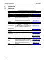
GX Configurator-ST Version 1.08J
MITSUBISHI
Operating Manual
MELSOFT
Integrated FA Software
SW1D5C-STPB-E
GX Configurator ST
© Mitsubishi Electric Corporation © 2003 - 2012, all rights reserved
All rights reserved. No parts of this work may be reproduced in any form or by any means - graphic, electronic, or
mechanical, including photocopying, recording, taping, or information storage and retrieval systems - without the
written permission of the publisher.
Products that are referred to in this document may be either trademarks and/or registered trademarks of the
respective owners. The publisher and the author make no claim to these trademarks.
While every precaution has been taken in the preparation of this document, the publisher and the author assume no
responsibility for errors or omissions, or for damages resulting from the use of information contained in this
document or from the use of programs and source code that may accompany it. In no event shall the publisher and
the author be liable for any loss of profit or any other commercial damage caused or alleged to have been caused
directly or indirectly by this document.
Printed: May 2012
INTRODUCTION
Thank you for choosing the Mitsubishi MELSOFT Series Integrated FA software.
Read this manual and make sure you understand the functions and performance of MELSOFT series
thoroughly in advance to ensure correct use.
CONTENTS
6
1 Introduction
................................................................................................................................... 7
1.1 Safety Precautions
...................................................................................................................................
8
1.2 Documentation
layout
14
1.3 Terms and...................................................................................................................................
Abbreviations
...................................................................................................................................
19
1.4 What's new
in version 1.08J?
...................................................................................................................................
20
1.5 Notes for upgrading
users
22
2 Overview
2.1 Features ................................................................................................................................... 22
...................................................................................................................................
27
2.2 How do I ...
?
29
3 System Configuration
................................................................................................................................... 29
3.1 System Configuration
30
3.2 Operating ...................................................................................................................................
Environment
32
4 Function list
................................................................................................................................... 32
4.1 Function list
4.2 Menu list ................................................................................................................................... 33
37
5 Operation Procedures
...................................................................................................................................
37
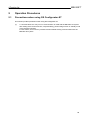
5.1 Precautions
when using GX Configurator-ST
38
5.2 Edit mode...................................................................................................................................
operation procedure
38
5.3 Diagnosis ...................................................................................................................................
mode operation procedure
40
6 Installation and uninstallation
6.1 Installation................................................................................................................................... 40
6.1.1 Installation
...................................................................................................................................................................................
procedure
40
6.1.2 Installing
...................................................................................................................................................................................
GX Configurator-ST
41
................................................................................................................................... 47
6.2 Uninstallation
...................................................................................................................................
49
6.3 Starting GX
Configurator-ST
51
6.4 Exiting GX...................................................................................................................................
Configurator-ST
53
7 Screen layout and display switching
................................................................................................................................... 53
7.1 Screen layout
...................................................................................................................................
54
7.2 Display switching
and window rearranging operations
55
7.3 Details of ...................................................................................................................................
toolbar
56
7.4 Details of ...................................................................................................................................
module configuration window
7.4.1 Details
...................................................................................................................................................................................
of rack display
58
7.4.2 Details
...................................................................................................................................................................................
of module list
59
3
7.4.3 Details
...................................................................................................................................................................................
of w izard area
63
7.4.4 Details
...................................................................................................................................................................................
of information area
64
8 Project creation
67
68
8.1 Creating a...................................................................................................................................
new project
...................................................................................................................................
70
8.2 Opening an
existing project
...................................................................................................................................
71
8.3 Closing the
project
72
8.4 Saving the...................................................................................................................................
project
8.4.1 Save
................................................................................................................................................................................... 72
8.4.2 Save
...................................................................................................................................................................................
as
73
...................................................................................................................................
74
8.5 Verifying the
projects
8.5.1 n:n...................................................................................................................................................................................
verify
74
8.5.2 Verify
...................................................................................................................................................................................
result
77
8.5.3 1:n...................................................................................................................................................................................
verify
79
...................................................................................................................................
82
8.6 Printing the
project data
8.6.1
8.6.2
8.6.3
8.6.4
Setting
...................................................................................................................................................................................
up the printer
86
Setting
...................................................................................................................................................................................
a page layout
88
Preview
...................................................................................................................................................................................
ing a print image
92
Print
...................................................................................................................................................................................
Examples
94
9 Editing the project
96
96
9.1 Adding the...................................................................................................................................
module
9.1.1 Adding
...................................................................................................................................................................................
the module w ith the "Add module" screen
96
9.1.2 Adding
...................................................................................................................................................................................
the module w ith the "Wizard area"
100
107
9.2 Deleting ...................................................................................................................................
a module
108
9.3 Deleting ...................................................................................................................................
all modules
109
9.4 Copying ...................................................................................................................................
the module information
9.5 Undo
................................................................................................................................... 111
9.6 Redo
................................................................................................................................... 112
...................................................................................................................................
112
9.7 Rearranging
the modules
9.7.1 Rearranging
...................................................................................................................................................................................
the modules w ith the Rearrange dialog
112
9.7.2 Rearranging
...................................................................................................................................................................................
the modules w ith drag and drop
114
...................................................................................................................................
117
9.8 Parameter
setting
9.8.1
9.8.2
9.8.3
9.8.4
"Parameter
...................................................................................................................................................................................
setting" screen displaying operation
118
Setting
...................................................................................................................................................................................
the parameters
119
Uploading/dow
...................................................................................................................................................................................
nloading the parameters or verifying the parameters being edited and parameters w ithin module 121
Checking
...................................................................................................................................................................................
the parameters for errors
124
................................................................................................................................... 126
9.9 Option setting
...................................................................................................................................
130
9.10 Power distribution
check
...................................................................................................................................
132
9.11 Change head
module type
...................................................................................................................................
134
9.12 Change PROFIBUS-DP
head module protocol version
10 Downloading and uploading the parameters
137
138
10.1 Transfer ...................................................................................................................................
setup
................................................................................................................................... 141
10.2 Get system
143
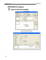
10.3 Get input...................................................................................................................................
/ output data settings (PROFIBUS-DP only)
...................................................................................................................................
144
10.4 Parameter
block write
...................................................................................................................................
146
10.5 Offset/Gain
setting of intelligent function modules
4
11 Monitor, Test
149
................................................................................................................................... 149
11.1 System Monitor
...................................................................................................................................
154
11.2 Module detail
information
...................................................................................................................................
160
11.3 Input/Output
monitor
...................................................................................................................................
165
11.4 Forced output
test
...................................................................................................................................
169
11.5 Master station
data communication monitor
11.5.1 Master
...................................................................................................................................................................................
station data communication monitor
169
11.5.2 Saving
...................................................................................................................................................................................
the communication data
174
...................................................................................................................................
175
11.6 PROFIBUS-DP
Network Parameter Monitor (PROFIBUS DP only)
11.6.1 PROFIBUS-DP
...................................................................................................................................................................................
Netw ork parameter monitor
175
11.6.2 Saving
...................................................................................................................................................................................
the PROFIBUS-DP netw ork parameter data
177
12 Online module operation
179
...................................................................................................................................
179
12.1 Reset head
module
...................................................................................................................................
180
12.2 Online module
change
12.2.1 Precautions
...................................................................................................................................................................................
for online module change
180
12.2.2 Procedures
...................................................................................................................................................................................
for online module change
182
12.2.3 Online
...................................................................................................................................................................................
module change from GX Configurator-ST
183
13 Reference
190
...................................................................................................................................
190
13.1 Key operations
list
................................................................................................................................... 191
13.2 Error messages
13.2.1
13.2.2
13.2.3
13.2.4
13.2.5
13.2.6
13.2.7
13.2.8
13.2.9
13.2.10
13.2.11
13.2.12
13.2.13
Index
Communication
...................................................................................................................................................................................
errors
191
Diagnostic
...................................................................................................................................................................................
errors
193
File
...................................................................................................................................................................................
errors
196
Forced
...................................................................................................................................................................................
output / offset and gain errors
197
Module
...................................................................................................................................................................................
addition and copying errors
200
Module
...................................................................................................................................................................................
configuration errors
204
Module
...................................................................................................................................................................................
deletion errors
206
Module
...................................................................................................................................................................................
parameter errors
207
Module
...................................................................................................................................................................................
selection errors
209
Module
...................................................................................................................................................................................
verify (compare) errors
210
Online
...................................................................................................................................................................................
change errors
211
Printing
...................................................................................................................................................................................
errors
213
System
...................................................................................................................................................................................
errors
214
219
5
1 Introduction
1
MELSOFT
Introduction
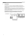
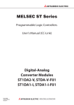
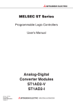
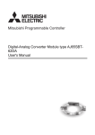
GX Configurator-ST is used for the configuration and diagnosis of SLICE systems.
MELSEC-ST systems consist of a head module (ST1H-PB for PROFIBUS-DP systems
or ST1H-BT for CC-Link systems) and a number of power supply or I/O modules
assembled in a rack.
These systems provide an easy and modular way to add I/O to a PROFIBUS-DP or CCLink system, without having to install separate wiring to many separate I/O modules. The
I/O from each module is grouped into individual data input/output areas for transmission
to/from the network master station.
GX Configurator-ST connects to the communication port of the ST1H-PB or ST1H-BT
head module using an appropriate programming cable. The head module will
independently act as a slave station on a PROFIBUS-DP or CC-Link network.
E xam ple CC-lin k s ys tem
6
1 Introduction
1.1
MELSOFT
Safety Precautions
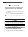
SAFETY PRECAUTIONS
(Read these precautions before using.)
When using Mitsubishi equipment, thoroughly read this manual and the associated manuals
introduced in this manual. Also pay careful attention to safety and handle the module properly.
The precautions given in this manual are concerned with this product. Refer to the user's manual of
the network system to use for a description of the network system safety precautions.
These SAFETY PRECAUTIONS classify the safety precautions into two categories: "DANGER" and
"CAUTION".
Depending on circumstances, procedures indicated by
CAUTION may also be linked to serious
results.
In any case, it is important to follow the directions for usage.
Store this manual in a safe place so that you can take it out and read it whenever necessary.
Always forward it to the end user.
[Design Instructions]
DANGER
For data change and status control made to the MELSEC-ST system which is running
from a Personal computer, configure the interlock circuit externally so that the system
safety is ensured. The action to be taken for the system at the occurrence of
communication errors caused by such as loose cable connection must be determined
for online operation of MELSEC-ST system from Personal computers.
CAUTION
Be sure to read the manual careful and exercise an appropriate amount of caution
connecting to MELSEC-ST system and performing online operations (head module
resetting, forced output test, etc.) while the personal computer is operating.
When replacing the module online, make sure to observe the procedure specified for the
module.
For I/O module, refer to the chapter of online module change in the head module user's
manual; for each intelligent function module, refer to the same chapter in the
corresponding intelligent function module user's manual.
7
1 Introduction
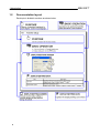
1.2
Documentation layout
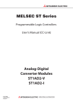
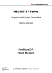
Each topic is divided in sections as shown below.
8
MELSOFT
1 Introduction
MELSOFT
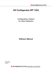
In addition, there are also the following explanations.
Describes application operation if there are multiple purposes and the basic operation and display/
setting data do not provide enough information.
Provides information relevant to that page, e.g. the items you should be careful of and the functions
you should know.
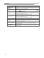
The following table lists the symbols used in this manual and their definitions.
Symbol
Description
Represents the menu name of the menu bar.
[
]
[
]
[
] indicates a drop-down menu.
Example: [File]
(
)
[New] menu
Represents the tool button on the toolbar corresponding to the drop-down
menu.
Example: [File]
[Save] menu (
)
Represents the item name in the dialog box.
"
"
Example: "File name"
Represents a button.
Example:
button
Represents the tab in the dialog box.
<<
>>
Example: <<Verify All Modules>> tab
9
1 Introduction
MELSOFT
How to read manual (For CC-Link)
In this manual, remote I/O, remote registers and message transmission areas for CC-Link are
represented with Br, Wr, Cr, Bw, Ww, Cw.
(1) Data symbol
(2) Head Module
Master Station
(a) Remote input (RX)
Data symbol
to
Area name
Unit
Detail data No.
notation
Bit input area
1 bit / symbol
Hexadecimal
Area name
Unit
Detail data No.
notation
Word input area
1 word / symbo
l
Hexadecimal
Area name
Unit
Detail data No.
notation
Command result
area
1 word / symbo
l
Decimal
(b) Remote register (RWr)
Data symbol
to
(c) Message transmission
Data symbol
10
1 Introduction
MELSOFT
(3) Master station
Head module
(a) Remote output (RY)
Data symbol
Area name
Unit
Detail data No.
notation
Bit output area
1 bit / symbol
Hexadecimal
Area name
Unit
Detail data No.
notation
Word output area
1 word / symbo
l
Hexadecimal
Area name
Unit
Detail data No.
notation
Command execution
area
1 word / symbo
l
Decimal
to
(b) Remote register (RWw)
Data symbol
to
(c) Message transmission
Data symbol
How to read manual (For PROFIBUS-DP)
In this manual, remote I/O, remote registers and message transmission areas for PROFIBUSDP are represented with Br, Wr, Cr, Bw, Ww, Cw.
(1) Data symbol
11
1 Introduction
MELSOFT
(2) Input send data
Data symbol
Area
Unit
Detail data No. notation
to
Bit Input Area
1 bit / symbol
Hexadecimal
to
Error Information Area
1 bit / symbol
Hexadecimal
to
Module Status Area
1 bit / symbol
Decimal
Command Result Area
1 word / symbol
Decimal
Word Input Area
1 word / symbol
Hexadecimal
*1
to
*1: The detailed area of the command result area uses the following symbols.
Data symbol
Area
Command Execution Result
Start Slice No. of Execution Target
Executed Command No.
Response Data 1
Response Data 2
12
1 Introduction
MELSOFT
(3) Output receive data
Data symbol
Area
Unit
Detail data No. notation
to
Bit Output Area
1 bit / symbol
Hexadecimal
to
Error Clear Area
1 bit / symbol
Hexadecimal
1 word /
symbol
Decimal
to
System Area
*1
Command Execution Area
1 word / symb
ol
Decimal
Word Output Area
1 word / symb
ol
Hexadecimal
to
*1: Following shows the data symbols and the corresponding detail areas within the command
execution area.
Data symbol
Area
Start Slice No. of Execution Target
Command No. to be executed
Argument 1
Argument 2
13
1 Introduction
1.3
MELSOFT
Terms and Abbreviations
Unless otherwise specified, this documentation uses the following terms and abbreviations to explain
the head module.
Term/Abbreviation
Head module
PROFIBUS-DP
CC-Link
Master module
RDMSG
Bus refreshing module
Power feeding module
Power distribution
module
Base module
Input module
Output module
Intelligent function
module
I/O module
Slice module
MELSEC-ST system
External power supply
GX Configurator-ST
Configuration software
14
Description
Generic term for the ST1H-PB MELSEC-ST PROFIBUS-DP head module,
ST1H-BT MELSEC-ST CC-Link head module.
Abbreviation for PROFIBUS-DP network.
Abbreviation for Control & Communication Link system.
Abbreviation for the QJ61BT11N used as a master station.
Generic term for G.RDMSG and GP.RDMSG.
Module that distributes external system power and auxiliary power to the head
module and slice modules.
Module that distributes external auxiliary power to slice modules.
Generic term for the bus refreshing module and power feeding module.
Generic term for a module that transfers data between the head module and
slice modules, and between the slice modules and external devices
(including wiring).
Generic term for modules that handle input data in units of bits.
Generic term for modules that handle output data in units of bits.
Generic term for modules that handle input/output data in units of words.
Generic term for input modules and output modules.
Generic term for power distribution modules, I/O modules, and intelligent
function modules that can be mounted on base modules.
Generic term for a system that is that is composed of a head module, slice
modules, an end plate and end brackets.
Generic term for external system power and auxiliary power.
Generic product name for SWnD5C-STPB-E. (“n” denotes Version 1 or later.)
Software used to set slave parameters for head modules and slice modules
in PROFIBUS-DP. (e.g. GX Configurator-DP).
1 Introduction
MELSOFT
Term definition for CC-Link
The following explains the meanings and definitions of the terms used in this documentation when
using CC-Link.
Term/Abbreviation
Cyclic transmission
Master station
Local station
Remote I/O station
Remote device station
Remote station
SB
SW
RX
RY
RWr
RWw
Remote net Ver. 1 mode
Remote net Ver. 2 mode
I/O data
Bit input area
Bit output area
Word input area
Word output
area
Command result
area
Description
A communication method by which remote I/O data and remote register data
are transferred periodically.
This station controls the entire data link system.
One master station is required for one system.
A station that has a programmable controller CPU and can communicate with
the master station and other local stations.
A remote station that can only use bit data. (Input from or output to external
devices)
(AJ65BTB1-16D, AJ65SBTB1-16D or others).
A remote station that can use both bit and word data. (Input from or output to
external devices, analog data conversion) (ST1H-BT, AJ65BT-64AD, AJ65BT64DAV, AJ65BT-64DAI or others)
Generic term for remote I/O stations and remote device stations.
Controlled by the master station.
Link special relay (for CC-Link).
Bit data that indicate the module operating status and data link status of the
master/local station.
Link special register (for CC-Link).
Data in units of 16 bits, which indicate the module operating status and data
link status of master/local station.
Remote input (for CC-Link).
Bit data that are input from remote stations to the master station.
Remote output (for CC-Link).
Bit data that are output from the master station to remote stations.
Remote register (Read area for CC-Link).
Data in units of 16 bits, which are input from remote device stations to the
master stations.
Remote register (Write area for CC-Link).
Data in units of 16 bits, which are output from the master station to remote
device stations.
Select this mode when extended cyclic setting is not needed or when the
QJ61BT11 is replaced with the QJ61BT11N.
Select this mode when creating a new system with extended cyclic setting.
Data transferred between the head module and the master station.
Bit input data of each module.
Input data are sent from the head module to the master station through
remote input (RX).
Bit output data of each module.
Output data are received from the master station to the head module through
remote output (RY).
Word (16-bit) input data of an intelligent function module.
Input data are sent from the head module to the master station through
remote register (RWr).
Word (16-bit) output data of an intelligent function module.
Output data are received from the master station to the head module through
remote register (RWw).
Information that indicates a command result.
This information is stored in Setting data (area starting from (D1) + 1) of the
RDMSG instruction of the master station.
15
1 Introduction
Term/Abbreviation
Command
execution area
Number of occupied I/O
points
Slice No.
Slice position No.
Start slice No.
Command
Command parameter
ST bus cycle time
16
MELSOFT
Description
Information for executing a command.
This information is stored in Setting data (area starting from (S2) + 1) of the
RDMSG instruction of the master station.
The area, which is equivalent to the occupied I/O points, is occupied in
Bit
input area /
Bit output area.
The number assigned to every 2 occupied I/O points of each module.
The numbers are assigned in ascending order, starting from “0” of the head
module. (The maximum value is 127.)
This is used for specifying a command execution target.
The number that shows where the slice module is physically installed.
The numbers are assigned in ascending order, starting from “0” of the head
module. (The maximum value is 63.)
This is used for specifying a command execution target.
The start slice No. assigned to the head module and slice modules.
Generic term for requests that are executed by the master station for reading
each module’s operation status, setting intelligent function module command
parameters or various controls.
Generic term for parameter set in commands or GX Configurator-ST.
All of the parameters set for the head module and slice modules are
command parameters.
Processing time for the head module to refresh the input or output status of
each slice module.
1 Introduction
MELSOFT
Term definition for PROFIBUS-DP
The following explains the meanings and definitions of the terms used in this documentation when
using PROFIBUS-DP.
Term/Abbreviation
QJ71PB92V
QJ71PB92D
A1SJ71PB92D
AJ71PB92D
PROFIBUS-DPV0
PROFIBUS-DPV1
PROFIBUS-DPV2
GX Configurator-DP
Master station
Slave station
Repeater
Bus terminator
FDL address
Extended diagnostic
information
Slave parameter
GSD file
Description
Abbreviation for the QJ71PB92V PROFIBUS-DP master module.
Abbreviation for the QJ71PB92D PROFIBUS-DP interface module.
Abbreviation for the A1SJ71PB92D PROFIBUS-DP interface module.
Abbreviation for the AJ71PB92D PROFIBUS-DP interface module.
A basic version of PROFIBUS-DP.
The following functions are executable:
I/O data exchange
Diagnostic information notification
etc.
A PROFIBUS-DP version for which the following functions have been added to
the basic functionality of PROFIBUS-DPV0
Acyclic communication
Alarm function
etc.
A PROFIBUS-DP version for which the following functions have been added to
the PROFIBUS-DPV1 functionality
Time stamping
etc.
SWnD5C-PROFID-E type products. ("n" means version 4 or later.)
Class 1 master station that communicates I/O data with slave stations.
A device that exchanges I/O data with a DP-Master (Class 1). (ST1H-PB, etc)
Device that connects PROFIBUS-DP segments.
Terminator that is connected to both ends of each PROFIBUS-DP segment
Address assigned to the master station/slave station.
The FDL address is set within the range from 0 to 99.
Diagnostic information specific to each DP-Slave
Each of DP-Slaves notifies of it to the DP-Master when an error is detected.
The slave station parameter (including user parameter) set by the master
station.
The setting items are described in the GSD file.
The electronic file that includes description of the slave station parameter.
The file is used when setting slave parameters by configuration software,
which is supported by the master station.
Data sent from the head module to the master station.
The data consists of the following areas.
Bit Input Area (head module version A only)
Information Area
Input data
Error Information Area (head module version A only)
Module Status Area (head module version A only)
Command Result Area (head module version A only)
Word Input Area
17
1 Introduction
MELSOFT
Term/Abbreviation
Description
Data that the head module receives from the master station.
The data consists of the following areas.
Bit Output Area (head module version A only)
Request Area
Output data
Error Clear Area (head module version A only)
System Area (head module version A only)
Command Execution Area (head module version A only)
Word Output Area
I/O data
Global control
Bit input area
Bit output area
Word input area
Word output
area
Information area
Request area
Number of occupied I/O
points
Slice No.
Command
ST bus cycle time
Bus cycle time
18
Data (input data, output data) transferred between the head module and the
master station.
This function enables synchronization command transmission for I/O data
from a DP-Master (Class 1) to DP-Slaves.
Bit input data of each module.
Bit output data of each module
Word (16-bit) input data of an intelligent function module.
In the case of analog input module, the digital output data value is stored.
Word (16-bit) output data of an intelligent function module.
In the case of analog output module, the digital setting data value is stored.
Bit/Word input data for checking each module status and command execution
results.
Bit/Word output data for requesting each module to clear errors/to execute
commands.
The area, that is equivalent to the occupied I/O points, is occupied in
Bit
Input Area/
Bit Output Area.
No. assigned to every 2 occupied I/O points of each module. This numbering
starts by assigning "0" to the head module and then proceeds in ascending
order. (The maximum value No. is 127).
The No. is used for specifying the execution target.
Requesting from the master station in order to read the module status, to set/
control the intelligent function module command parameters.
Processing time for the head module to refresh the input/output status of each
slice module.
PROFIBUS-DP processing time for the master station to perform cyclic
transfer with each slave station.
1 Introduction
1.4
MELSOFT
What's new in version 1.08J?
Version 1.08J introduces a number of new features to improve the functionality and
usability of GX Configurator-ST, such as:
Support for Microsoft® Windows ® 7 32-bit and 64-bit operating systems.
19
1 Introduction
1.5
MELSOFT
Notes for upgrading users
If you have upgraded from the previous version of GX Configurator-ST, you can still reuse
the files that you created with the last version. These files can be opened normally, and
will be upgraded automatically when they are saved.
Although PROFIBUS-DP files created in this version can be reopened in the
last version of the software, it is generally advisable not to switch between
versions of the software when configuring a file. After saving a file once in
the current version of GX Configurator-ST, opening it in earlier versions is
not recommended.
GX Configurator-ST 1.06G will only partially work with the new PROFIBUS-DP head
module.
Head module set to PROFIBUS-DP version A:
If the head module is set to version A, there will be no problem as GX Configurator-ST
1.06G is fully compatible with this head module version.
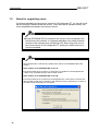
Head module set to PROFIBUS-DP version B:
If the head module is set to version B, GX Configurator-ST 1.06G cannot communicate
with the head module due to changes to the internal structure. Attempting to connect to
the head module will display the error below.
20
1 Introduction
MELSOFT
The user interface is very similar to the versions that you have used before, but now when
you start the application you will be taken through the first configuration steps with a
'wizard' interface. In the main configuration display, the module list from the previous
version is now just the bottom left section of a larger 'module configuration' window, which
also shows a graphical display of the configured system, a list of modules for addition and
details of the module selected to be added.
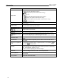
To read more about these features, see the sections shown below:
Feature
PROFIBUS-DP description
First steps using the wizard
Creating a new project
The module configuration window
Screen layout and display switching
If you are stuck while using the application, press
help file.
to show the relevant section of the
21
1 Introduction
2
MELSOFT
Overview
GX Configurator-ST is the configuration software dedicated to the MELSEC-ST system.
2.1
Features
(1) Project creation of MELSEC-ST system
(a) Uploading module data to create project
A project can be created easily by uploading the system configuration and parameters
from the MELSEC-ST system.
22
2 Overview
MELSOFT
(b) Changing system configuration to edit project
A project can be edited by changing the system configuration, e.g. adding or
rearranging modules.
(2) Monitoring MELSEC-ST system
(a) MELSEC-ST system status can be easily checked.
GX Configurator-ST provides an image to show the statuses of the head/slice modules
that comprise the MELSEC-ST system on the “System Monitor” screen. Therefore,
these module statuses can be checked easily.
23
2 Overview
MELSOFT
(b) I/O module or intelligent function module can be changed online from
GX Configurator-ST
By using online module change, the faulty I/O module or intelligent function module can
be changed with normal module without the PROFIBUS-DP or CC-Link network being
stopped.
GX Configurator-ST allows online module change to be made easily by screen-guided
operation without operation of the head module switches.
(c) Output test can be done without affecting PROFIBUS-DP or CC-Link
network
In a forced output test, outputs can be tested using the
Word Output and
The user can specify any
Error Clear.
Bit Output,
Error Clear of the head module or slice module.
Bit Output,
Word Output and
As only the
Bit Output,
Word Output and
Error Clear are
used for the forced output test, output data not used in the test are not affected.
In the forced output test, therefore, an output test can be conducted without affecting
the PROFIBUS-DP or CC-Link network.
24
2 Overview
MELSOFT
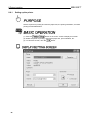
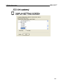
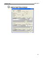
(3) Parameter setting of slice module
(a) Parameter setting of intelligent function module
The "Parameter Setting" screen displays a list of module parameters.
Parameter setting can be made on this list.
As it includes functions to upload and verify data, and to check the setting errors, the
parameters can be confirmed easily.
25
2 Overview
MELSOFT
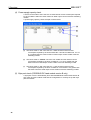
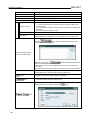
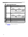
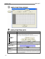
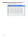
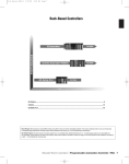
(4) Power supply capacity check
A check can be made to see if the sum of 5VDC internal current consumption required
by each module is within the 5VDC maximum rated output current of the bus refreshing
module.
A power supply capacity check example is shown below.
(a) The check result is "OK" since the sum 1.800A of 5VDC internal current
consumption required by the head module No. 0 and slice modules No. 2 to 15
is not greater than the 5VDC maximum rated output current 2.000A of the bus
refreshing module.
(b) The check result is "ERROR" since the sum 2.280A of 5VDC internal current
consumption required by the slice modules No. 17 to 42 is greater than the
5VDC maximum rated output current 2.000A of the bus refreshing module.
(c) The check result is "OK" since the sum 1.145A of 5VDC internal current
consumption required by the slice modules No. 44 and later is not greater than
the 5VDC maximum rated output current 2.000A of the bus refreshing module.
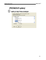
(5) Byte pack check (PROFIBUS-DP head module version B only)
A byte pack check is automatically done with PROFIBUS-DP head module version B.
This check ensures in offline mode that the configuration is correctly set up with byte
packed modules.
26
2 Overview
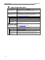
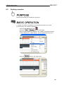
2.2
MELSOFT
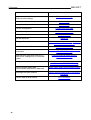
How do I ... ?
This section will list things that you may wish to achieve with the software, and the
different ways in which these can be done. There may be several ways to get the same
result, for example modules can be added or deleted using several different methods.
How do I...?
Create a new system
Set up the communication port
Instructions
Creating a new project
Transfer setup dialog
Read the configuration from the SLICE
hardware
Get system
Use the module configuration window
Details of module configuration window
Add modules to the configuration
Adding the module with the "Add module"
screen
Adding the module with the "Wizard area"
Delete modules from the configuration
Deleting a module
Deleting all modules
Rearrange the modules in the configuration
Rearrange modules
Drag and drop modules
Drag and drop
Set module parameters
Parameter setting
Download parameters to several modules
at once
Parameter block write
Compare parameter details with those
stored in another project file
Verifying the projects
Compare parameter details with those on
the SLICE hardware
Uploading / downloading the parameters
Copy modules from another configuration
file
Copying the module information
Use GX Configurator-ST for diagnostics
System monitor
Show module details (address ranges)
Module detail information
View module input/output data
Input/Output monitor
Test / calibrate module outputs
Forced output test
Set offset/gain settings for a module
Offset/gain settings
Change the head module type after the
system has been configured
Change head module type
27
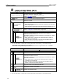
2 Overview
How do I...?
Swap modules while the system is running
(Online module change)
Instructions
Online module change
Set module options
Option setting
Change module labels
Option setting
Print the configuration
Printing the project data
Check the total power consumption
Power distribution check
Use the toolbar
Use the status bar
Change to/from edit/online mode
Reset the head module
View the PROFIBUS-DP network
parameters
Read the point mode and 'without Wr' /
'without Ww' settings from a connected
system
Change the head module protocol version
28
MELSOFT
Details of toolbar
Status bar
Edit mode operation procedures / Diagnosis
mode operation procedures
Reset the head module
PROFIBUS-DP network parameter monitor
(PROFIBUS-DP only)
Reading input/output data settings
(PROFIBUS-DP only)
Change PROFIBUS-DP head module
protocol version (PROFIBUS-DP only)
View the master station data
communication parameters / data area
Master station data communication monitor
Rearrange the open windows
Display switching and window rearranging
operations
Find out what an error means
Error messages
2 Overview
MELSOFT
3
System Configuration
3.1
System Configuration
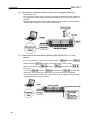
The following shows the configuration where a personal computer is connected to the MELSEC-ST
system.
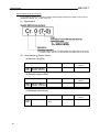
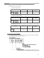
*1 : Use either of the following cables as the RS-232 cable.
Manufacturer name
Mitsubishi Electric
Beijer ELECTRONICS
Model name
QC30R2
SC-Q QC30R2
29
3 System Configuration
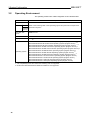
3.2
MELSOFT
Operating Environment
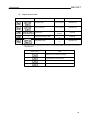
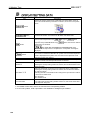
The operating environment of GX Configurator-ST is indicated below.
Item
Description
Computer main unit
CPU
Required
memory
Refer to the following table "Used operating system and performance required for
personal computer".
Hard disk free
space
60MB or more
Disk drive
CD-ROM disk drive
Display
1024
Operating system
Microsoft® Windows® 2000 Professional Operating System (English version)
Microsoft® Windows® XP Professional Operating System (English version) *1, 2
Microsoft® Windows® XP Home Edition Operating System (English version) *1, 2
Microsoft® Windows Vista® Home Basic Operating System (English version) *2
Microsoft® Windows Vista® Home Premium Operating System (English version) *2
Microsoft® Windows Vista® Business Operating System (English version) *2
Microsoft® Windows Vista® Ultimate Operating System (English version) *2
Microsoft® Windows Vista® Enterprise Operating System (English version) *2
Microsoft® Windows® 7 Home Premium Operating System (English version)
Microsoft® Windows® 7 Professional Operating System (English version)
Microsoft® Windows® 7 Ultimate Operating System (English version)
Microsoft® Windows® 7 Enterprise Operating System (English version)
768 dot or more resolution
*1: "XP compatibility mode" and "Fast user switching" are not supported.
*2: 64-bit OS for Windows® XP and Windows Vista® are not supported.
30
3 System Configuration
MELSOFT
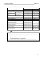
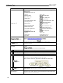
Used operating system and performance required for personal computer
Performance Required for Personal Computer
Operating system
CPU
Required memory
Windows® 2000 Professional
Pentium® 133MHz or more
64MB or more
Windows® XP
Professional
Pentium® 300MHz or more
128MB or more
Pentium® 300MHz or more
128MB or more
Windows Vista® Home Basic
Pentium® 1GHz or more
1GB or more
Windows Vista® Home Premium
Pentium® 1GHz or more
1GB or more
Windows Vista® Business
Pentium® 1GHz or more
1GB or more
Windows Vista® Ultimate
Pentium® 1GHz or more
1GB or more
Windows Vista® Enterprise
Pentium® 1GHz or more
1GB or more
Windows® 7 Home Premium
Pentium® 1GHz or more
1GB or more (32-bit)
2GB or more (64-bit)
Windows® 7 Professional
Pentium® 1GHz or more
1GB or more (32-bit)
2GB or more (64-bit)
Windows® 7 Ultimate
Pentium® 1GHz or more
1GB or more (32-bit)
2GB or more (64-bit)
Windows® 7 Enterprise
Pentium® 1GHz or more
1GB or more (32-bit)
2GB or more (64-bit)
Windows® XP Home
Edition
"XP compatibility mode"
and "Fast user switching"
are not supported.
• The following features are not available for use with Windows ® XP, Windows Vista® and
Windows ® 7. If used, this product may not function normally.
Application startup in Windows ® compatibility mode
Fast user switching
Remote desktop
Large fonts (detailed setting in Screen properties)
• On Windows Vista® and Windows ® 7 authority of USER or higher level must be used.
31
3 System Configuration
4
Function list
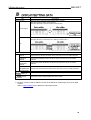
4.1
Function list
MELSOFT
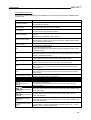
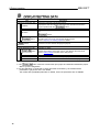
The functions of GX Configurator-ST are indicated below.
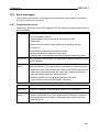
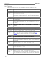
Function
Description
System configuration
Registers modules into the system by model name.
setting
Parameter Setting
Option Settings
Power Distribution
Check
Tests the
Offset/Gain Setting
Reset Head Module
Change head
module type
Change head
module protocol
version
Module Detail
Information
Online Module
Change
PROFIBUS-DP
Network Parameter
Monitor
Master Station Data
Communication
Monitor
32
'Editing the project'
Sets the parameters to the intelligent function module.
'Parameter setting'
Sets the label name, base module etc. for the module.
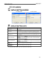
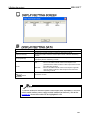
'Option setting'
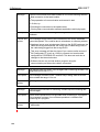
Checks whether the 5VDC internal current
'Power distribution check'
consumption of the bus refreshing module is
sufficient.
Monitors the statuses of the head and slice modules.
'System monitor'
System Monitor
Module configuration,
Uploads/downloads the module configuration and
parameter upload/
parameters.
download
Input/Output Monitor Monitors the input data and output data.
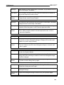
Forced Output Test
Reference Section
Bit Output,
'Downloading and
uploading the parameters'
'Input/Output monitor'
Word Output
and
Error Clear of the head module or slice
module without stopping the PROFIBUS-DP or CCLink network.
'Forced output test'
Sets the offset and gain values of the intelligent
function modules (ST1AD2-V, etc.).
Resets the head module.
'Offset/Gain setting of
intelligent function modules'
'Reset head module'
Changes the head module type (in edit mode).
'Change head module type'
Changes the head module protocol version (in edit
mode) - PROFIBUS-DP only.
'Change PROFIBUS-DP
head module protocol
version'
Shows the module detail information and monitors
'Module detail information'
the corresponding module error status.
Changes the I/O module or intelligent function module
'Online module change'
online from GX Configurator-ST.
Monitors the slave parameters and PROFIBUS-DP
'PROFIBUS-DP network
network parameters sent from the master station of
parameter monitor'
PROFIBUS-DP to the MELSEC-ST system to show the
results for confirmation.
Monitors I/O data between the master station and
head module.
'Master station data
communication monitor'
4 Function list
4.2
MELSOFT
Menu list
This section explains the menus of GX Configurator-ST.
The menu screens in this section are different from the actual ones.
Actually, some menu items are not selectable depending on the operation status of
GX Configurator-ST.
For the purpose of explanation, all the menu items are shown as selectable.
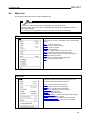
[File] menu
The [File] menu includes project file operation, print and
other functions. For more information, refer to the following
sections:
New - create a new project
Open - open an existing project
Close - close the project
Save - save the project
Save as - save the project with another name
Verify - compare modules with another project
Copy - copy module information from another project
Print - print the project data
Recent files - open a recently-used project
Exit - close GX Configurator-ST
[Edit] menu
The [Edit] menu includes the functions for module
configuration setting and parameter setting. For more
information, refer to the following sections:
Undo - reverse the last edit operation
Redo - reverse the last undo operation
Add - add a module to the configuration
Rearrange - change the order of modules
Delete - delete a module
All delete - delete all modules
Parameter setting - change module parameter settings
Option - change module options
Change head module - change head module type
Power distribution check - test power consumption
33
4 Function list
MELSOFT
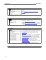
[View] menu
The [View] menu includes the function to display/hide each
screen.
Refer to 'Display switching and window rearranging
operations' for details of each menu item.
[Mode] menu
The [Mode] menu includes the functions to switch between
the edit mode and diagnosis mode.
Refer to 'Edit mode operation procedure' for details of the
[Edit] menu item.
Refer to 'Diagnosis mode operation procedure' for details
of the [Diagnosis] menu item.
[Online] menu
The [Online] menu includes the functions for connection to
the head module and online operation of the head module.
For more information, refer to the following sections:
Transfer setup - select communication port to use
Get system - read configuration from connected MELSECST system
Get input/output data settings - read input/output data
settings from MELSEC-ST system (PROFIBUS-DP only)
Input/Output monitor - monitor module input/output data
Forced output test - test outputs / error clear
Offset/Gain setting - change offset/gain settings
Parameter block write - download parameters as a batch
Reset the head module - restart the head module
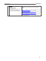
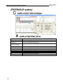
[Diagnostics] menu
34
4 Function list
MELSOFT
The [Diagnostics] menu includes the functions to diagnose
the system. For more information, refer to the following
sections:
Module detail information - show more details of a module
'Online module change' - swap out a module
'PROFIBUS-DP network parameter monitor' - view or export
network parameter data
'Master station data communication monitor' - view head
module data areas
35
4 Function list
MELSOFT
[Window] menu
The [Window] menu includes the functions to change the
screen layout of GX Configurator-ST.
Refer to 'Display switching and window rearranging
operations' for details of each menu item.
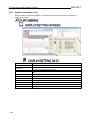
[Help] menu
The [Help] menu includes the functions to show the online
help, operate the GX Configurator-ST keys and confirm the
software version.
Contents
Key Operation List
Ab out
36
Shows the help file starting at the contents page.
Shows the key operation list page.
Shows the version number, copyright and licence
information.
4 Function list
MELSOFT
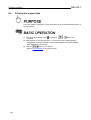
5
Operation Procedures
5.1
Precautions when using GX Configurator-ST
This section provides precautions when using GX Configurator-ST.
(1)
A communication error may occur if communication is made with the MELSEC-ST system
after setting of the resume function, suspend setting, power-saving function or standby mode
of the personal computer.
For this reason, do not set any of these functions before starting communication with the
MELSEC-ST system.
37
5 Operation Procedures
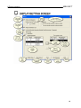
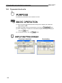
5.2
MELSOFT
Edit mode operation procedure
Create a new project, and edit and download it to the MELSEC-ST system.
.. Refer to 'Starting GX Configurator-ST'
... Refer to 'Opening an existing
project'
... Refer to
'Transfer setup'
... Refer to 'Editing the project'
... Refer to
'Get system'
... Refer to 'Parameter setting'
... Refer to
'Parameter setting
'
... Refer to 'Transfer setup'
... Refer to 'Parameter block w rite'
... Refer to 'Printing the project data'
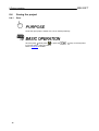
5.3
Diagnosis mode operation procedure
Confirm the error status and take corrective action, or perform the monitor/test, etc. of I/O data.
38
5 Operation Procedures
MELSOFT
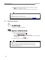
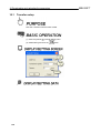
(1) Preparations for diagnosis mode
Make preparations for operation in the diagnosis mode.
Perform the following operation before starting operation in the diagnosis mode.
.. Refer to 'Starting GX Configurator-ST'
... Refer to 'Transfer setup'
... Refer to 'Get system'
... Refer to 'System monitor'
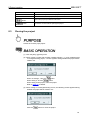
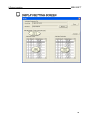
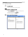
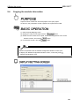
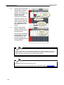
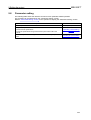
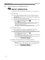
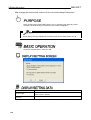
(2) Diagnosis mode operation procedure
Perform the operation explained in the reference section for each purpose of use.
Before starting the diagnosis mode operation, perform the operation in (1) of this section.
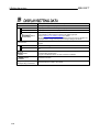
Purpose of use
To monitor the MELSEC-ST system.
To confirm the module where an error occurred.
To confirm the error definition.
To set the offset and gain values.
To confirm the I/O data.
To conduct the forced output test.
Reference section
'System monitor'
'Module detail information'
'Offset/Gain setting of intelligent function
modules'
'Input/Output monitor'
'Forced output test'
To monitor the master station data communication.
'Master station data communication
monitor'
To monitor the PROFIBUS-DP Network Parameters.
'PROFIBUS-DP network parameter
monitor'
To reset the head module.
To change the module online.
'Reset head module'
'Online module change'
39
5 Operation Procedures
6
MELSOFT
Installation and uninstallation
This chapter explains how to install and uninstall GX Configurator-ST.
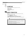
6.1
Installation
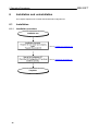
6.1.1
Installation procedure
.. Refer to 'Installing GX Configurator-ST'
.. Refer to 'Starting GX Configurator-ST'
40
6 Installation and uninstallation
6.1.2
MELSOFT
Installing GX Configurator-ST
The following indicates how to install GX Configurator-ST.
Microsoft® Windows ® XP Professional Operating System is used for explanation in this section.
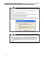
(1)
Before starting installation, exit all other applications operating on Windows ®.
(2)
The installer may not work normally because the update program of the operating
system or another companies software such as Windows ® Update and Java Update
may start automatically. Please install the driver after changing the settings of the
update program not to start automatically.
(3)
When installing GX Configurator-ST on any of the following operating systems, log on
using an administrator account (computer manager).
• Microsoft® Windows ® 2000 Professional Operating System
• Microsoft® Windows ® XP Professional Operating System
• Microsoft® Windows ® XP Home Edition Operating System
• Microsoft® Windows Vista® Home Basic Operating System
• Microsoft® Windows Vista® Home Premium Operating System
• Microsoft® Windows Vista® Business Operating System
• Microsoft® Windows Vista® Ultimate Operating System
• Microsoft® Windows Vista® Enterprise Operating System
• Microsoft® Windows ® 7 Home Premium Operating System
• Microsoft® Windows ® 7 Professional Operating System
• Microsoft® Windows ® 7 Ultimate Operating System
• Microsoft® Windows ® 7 Enterprise Operating System
(4)
Check whether or not GX Configurator-ST has been installed on the personal computer. If
it has already been installed, uninstall it, restart the personal computer, and then install
this software.
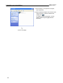
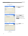
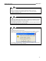
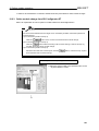
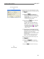
(1) Installing GX Configurator-ST
41
6 Installation and uninstallation
MELSOFT
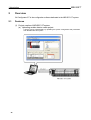
1) After powering on the personal computer,
start Windows ®.
2) Start Windows ® Explorer and click the drive
where the disk is inserted. Double-click
"Setup.exe" ( ).
To display Windows ® Explorer, choose
[Start]
[All Programs]
[Windows
Explorer].
(To the next page)
42
6 Installation and uninstallation
MELSOFT
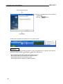
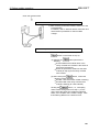
(From the previous page)
3) (When using Windows Vista® or Windows ®
7)
When the screen on the left is displayed,
click “Allow”.
4) On the left screen, click the
button.
5) Read and agree to the licence terms.
Then, click the
button.
Note: This dialog is only shown for
European product versions.
(To the next page)
43
6 Installation and uninstallation
MELSOFT
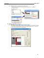
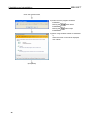
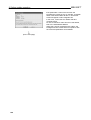
(From the previous page)
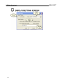
6) Enter a user name, company name and
serial number (where applicable), then
click the
button.
7) Specify an installation destination folder.
Then, click the
button.
The default is set to "C:\MELSEC\GX
Configurator ST 1.**". ("**" represents a
version number.)
To change the default setting, click the
button and specify a preferred
drive and folder.
8) Clicking the
installation.
(To the next page)
44
button will start
6 Installation and uninstallation
MELSOFT
45
6 Installation and uninstallation
MELSOFT
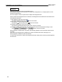
(From the previous page)
9) The left screen indicates that the installation
is completed.
Click the
button.
(Completion)
Installing GX Configurator-ST registers the icon as shown below.
REMARK
When any of the following operating systems is used, the registered icon is placed in the menu that
appears by selecting [Start]
[Programs]
[MELSOFT Application].
•
•
•
•
46
Microsoft® Windows ® 2000 Professional Operating System
Microsoft® Windows ® XP Professional Operating System
Microsoft® Windows ® Vista Operating System
Microsoft® Windows ® 7 Enterprise Operating System
6 Installation and uninstallation
6.2
MELSOFT
Uninstallation
This section explains the operation for removing GX Configurator-ST from the hard disk.
The screens used for explanation in this section are those of Windows ® XP Professional.
Though they differ slightly from the screens of Windows ® 2000 Professional or like, refer to
REMARKS and perform installation.
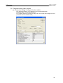
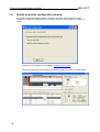
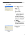
1) Double-click "Add or Remove Programs" on
the Control Panel.
To display the Control Panel, choose
[Start]
[Control Panel].
REMARKS
When using any of the following operating
systems, double-click "Add or Remove
Programs". To display the control panel,
choose [Start]
[Settings]
[Control
Panel].
• Windows ® 2000 Professional
• Windows ® XP Professional
For Windows Vista® and Windows ® 7, click
"Uninstall a program" on the Control Panel.
To display the Control Panel, select [Start]
[Control Panel].
2) Choose "Change or Remove Programs" and
then "GX Configurator ST Version 1.
**" ("**" represents a version number).
After selection, click the
button.
(To the next page)
47
6 Installation and uninstallation
MELSOFT
(From the previous page)
3) Confirm that the program should be
uninstalled.
Clicking the
uninstallation.
Clicking the
uninstallation.
button starts
button stops
4) (When using Windows Vista® or Windows ®
7)
When the screen on the left is displayed,
click "Allow".
(Completion)
48
6 Installation and uninstallation
6.3
MELSOFT
Starting GX Configurator-ST
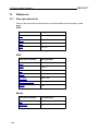
This section explains how to start GX Configurator-ST from the start menu.
1) Move the cursor from [Start]
[All Programs *1]
[MELSOFT Application].
*1: [Programs] is displayed when any of
the following operating systems is
used.
• Windows ® 2000 Professional
• Windows ® XP Professional
2) Click [GX Configurator ST **]
("**" represents a version number).
3) GX Configurator-ST starts.
49
6 Installation and uninstallation
MELSOFT
REMARK
Multiple GX Configurators-ST can be started to use.
Since different projects can be opened on multiple GX Configurators-ST, multiple projects can be
browsed simultaneously.
The same project cannot be opened from multiple GX Configurators-ST.
When multiple GX Configurators-ST are started, GX Configurators-ST started second and later have
the following restrictions.
1) The diagnosis mode cannot be used.
The [Mode]
[Diagnosis] menu ( ) cannot be clicked.
2) Get System cannot be executed.
The [Online]
[Get System] menu ( ) cannot be clicked.
3) Parameter Block Write cannot be executed.
The [Online]
[Parameter Block Write] menu cannot be clicked.
4) Parameter upload, download and verify cannot be executed on the Parameter Setting screen.
The
,
and
buttons cannot be clicked.
GX Configurator-ST started first can perform the following operation since the above restrictions do
not apply.
Even when GX Configurator-ST started first is exited, the above restrictions still apply to all
GX Configurator-ST instances that have started.
To remove the restrictions, restart GX Configurator-ST after exiting all the remaining GX ConfiguratorST instances.
50
6 Installation and uninstallation
6.4
MELSOFT
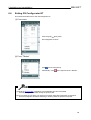
Exiting GX Configurator-ST
This section describes how to exit GX Configurator-ST.
(1) From menu
Click the [File]
[Exit] menu.
GX Configurator-ST ends.
(2) From "Titlebar"
Click
and choose [Close].
Alternatively, click
at the right end of the "Titlebar".
(1) While the print preview is displayed, GX Configurator-ST cannot be exited.
Exit GX Configurator-ST after closing the print preview.
(2) Do not restart or shut down your personal computer during GX Configurator-ST operation.
Exit GX Configurator-ST before restarting or shutting down the personal computer.
51
6 Installation and uninstallation
MELSOFT
REMARK
When a project is newly created, or modified but not yet saved, a dialog box appears asking whether
the project will be saved or not.
When not saving it, click the
button.
When saving it, click the
button.
When saving a new project, name the project.
Refer to 'Save as' for details.
52
6 Installation and uninstallation
7
MELSOFT
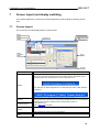
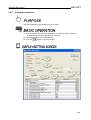
Screen layout and display switching
This chapter explains the screen layout of GX Configurator-ST and the display switching of each
area.
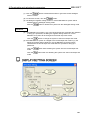
7.1
Screen layout
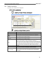
The screen layout of GX Configurator-ST is shown below.
Name
Description
Displays the file name of the open project.
When two or more GX Configurator-STs have been started, "Edit Mode only" is
displayed before each file name of the second and later ones.
Titlebar
When "Window" on GX Configurator-ST is maximized, the name of that "Window"
is displayed.
Menubar
Dropdown menu
Clicking each menu opens the corresponding "Dropdown menu". Then clicking a
"Dropdown menu" item will execute the corresponding function of
GX Configurator-ST.
Refer to 'Menu list' for details.
Toolbar
Click any of the buttons to execute the corresponding function of GX ConfiguratorST.
Refer to 'Details of toolbar' for more information.
Screen minimize
button
Click this button to minimize GX Configurator-ST.
53
7 Screen layout and display switching
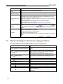
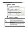
Name
MELSOFT
Description
Screen maxmize
Click this button to maximize GX Configurator-ST.
button
Exits GX ConfiguratorClick this button to exit GX Configurator-ST.
ST
This initially shows a configuration wizard. Once a configuration is being edited it
will display a list of modules registered to the project, graphically and as a list.
Double-click a module to set the parameters.
Module configuration Right-click the module to display the menu, and select a menu item to execute the
window
corresponding function.
Use ‘drag and drop’ in the graphical display to rearrange modules.
Use the ‘Wizard’ area to add modules.
Refer to 'Details of module configuration window' for more information.
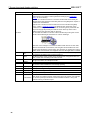
Displays the "Parameter Setting" screen, "Result Verify" screen, etc. Use
Window
to switch to the next window, or
+
+
to switch to the previous
window.
When the mouse pointer is moved over each "Dropdown menu" item, the
corresponding explanation is displayed.
The following information is also displayed.
• Current mode of GX Configurator-ST
• Station number or FDL address of the connected head module in the diagnosis
mode
Statusbar
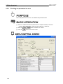
7.2
+
Display switching and window rearranging operations
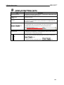
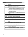
The following table shows how to display/hide bars and how to arrange windows.
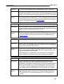
Operation
[View]
54
[Module Configuration Window]
Description
Displays or hides the "Module Configuration Window"
screen.
This operation can be performed in the edit mode only.
[View]
[Initialize Module Configuration
View Position]
Returns the display position of the "Module Configuration
Window" screen to the initial status.
This operation can be performed in the edit mode only.
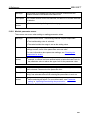
[View]
[System Monitor]
Displays or hides the "System Monitor" screen.
This operation can be performed in the diagnosis mode
only.
[View]
[Toolbar]
Displays or hides the "Toolbar".
[View]
[Statusbar]
Displays or hides the "Statusbar".
[Window]
[Cascade]
Overlays multiple "Windows" opened on GX Configurator-ST.
[Window]
[Tile Vertically]
Displays multiple "Windows" vertically.
[Window]
[Tile Horizontally]
Displays multiple "Windows" horizontally.
[Window]
[Arrange Icons]
Arranges the icons to which windows have been minimized.
[Window]
[Close All Windows]
Closes all "Windows".
When a "Window" is being edited, a confirmation message
is displayed.
7 Screen layout and display switching
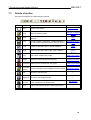
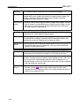
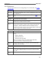
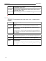
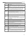
7.3
MELSOFT
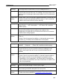
Details of toolbar
The buttons included in the Toolbar will be explained.
Button
Name
Description
Reference Section
'Creating a new
project'
New
Creates a new project.
Open
Opens the existing project.
Save
Saves the open project, whether it is new or existed
previously.
Print
Prints the module configuration, module information
list, and module detail information of the open project.
Undo
Restores to the status prior to the last operation.
'Undo'
Redo
Restores to the status prior to the "Undo" operation.
'Redo'
Add
Adds a slice module to the project.
'Adding the module'
Delete
Deletes the slice module from the project.
'Deleting a module'
All Delete Deletes all slice modules from the project.
Parameter
Sets the parameters of the intelligent function module.
Setting
Edit
Switches to the edit mode.
Diagnosis Switches to the diagnosis mode.
Get
System
Uploads the system configuration and the parameters
of each module from the head module.
About
Displays the software version of GX Configurator-ST.
'Opening an existing
project'
'Save'
'Printing the project
data'
'Deleting all modules'
'Parameter setting'
—
—
'Get system'
—
55
7 Screen layout and display switching
7.4
MELSOFT
Details of module configuration window
The module configuration window provides a ‘wizard’ to guide the user through the system
configuration. When GX Configurator-ST is first started, this will show the options for creating a
system:
Creating a new configuration is described in 'Creating a new project'.
When the configuration is being edited, the window changes to show four separate panes:
56
7 Screen layout and display switching
Name
MELSOFT
Description
Rack display
Displays a graphical representation of the assembled system. It can be used to
edit module details or rearrange modules using drag and drop.
The display items are described in 'Details of rack display'.
Module list
Shows the details of the modules, with the address ranges that they will use and
any label names assigned to them. The display items are described in 'Details of
module list'.
Wizard area
This is a continuation of the wizard screen shown when GX Configurator-ST first
starts, and can be used to add or delete modules. For more information, see
'Details of wizard area'.
Information area
This shows the details of the module selected for addition in the wizard area. The
display items are described in 'Details of information area'.
You can resize the areas by selecting the bars between them, and then clicking and
dragging with the mouse. The size of each area will be saved when the application exits, and
restored the next time the program starts. It can be reset from the 'View' menu 'Initialize
module configuration view position' item.
The following shortcut keys are available for use when the module configuration window is
active:
Key
Description
+
Switch to the rack display.
+
Switch to the module list
+
Switch to the wizard area
+
Switch between panes, in the order:
Rack display Module list Wizard area
Switch between panes in reverse order:
Rack display Wizard area
Module list
Rack display
Rack display
57
7 Screen layout and display switching
7.4.1
MELSOFT
Details of rack display
Displays a graphical representation of the assembled system. This can be useful to provide a quick
visual check for errors, as the graphical display should look like the physical hardware.
Item
58
Description
Modules
The rack starts at the left side with the head module, which always occupies
slot number zero. This should normally be followed by an ST1PSD bus
refreshing module, which is always required to provide power to the head
module and the first modules immediately after it.
The graphic for each module is shown in two parts; the upper half depends on
the module type, and the lower half shows the 'base module' which may be
different depending on the type of wiring used.
Left click on a module to select it. It will automatically be selected in the
module list as well. Many actions in the [Edit] menu require a module to be
selected first.
Right click on a module to select it and show a menu similar to the [Edit]
menu – refer to 'Editing the project' for details of each menu item. If the
module has a configuration error (such as consuming more power than the
last power supply will provide), this will be shown at the top of the menu.
Clicking on the item will show help on the error.
Scroll bar
If there are more modules in the configuration than the window can display,
there will be a scrollbar under the rack which can be used to view the
remaining modules
7 Screen layout and display switching
7.4.2
MELSOFT
Details of module list
This shows a list of modules in the configuration.
Item
Description
I/O Occupation Points (Bit) The total number of bits used by all the modules in the configuration.
I/O Occupation Points
The total number of words used by all the modules in the configuration.
(Word)
The limit on the number of input/output bits with the current optimisation
Max. Bit
mode, extended cyclic and stations settings.
The limit on the number of input/output words with the current optimization
Max. Word
mode, extended cyclic and stations settings.
This gives the optimization mode currently selected, either ‘priority high
speed’ (use more stations so data is read faster) or ‘priority min.
stations’ (reduce the number of stations used at the cost of reading the data
more slowly). This can only be changed for the SLICE system by setting a DIP
Mode
switch on the head module itself, although the selection can be changed here
to see what the effect of switching mode would be. When you switch to
diagnostics mode, the current DIP switch setting will be read from the SLICE
hardware.
This shows the configuration setting you will need to correctly configure the
Configuration setting
head module in GX Works2, GX Developer or GX IEC Developer.
By increasing the number of cycles taken to read the data, the number of
stations used can be reduced, however this means that the data will take
Exp. cyclic setting
longer to read in total. This value is calculated based on the optimization
mode setting.
59
7 Screen layout and display switching
Item
Excl. station count
List area
No.
Slice
Module
Name
Br(HEX)
MELSOFT
Description
The number of stations used for communications. Using more stations
increases the speed at which data is read, but reduces the number of other
devices that can be used on the CC-Link bus. This value is calculated based
on the optimization mode setting.
This shows a list of modules in the configuration.
Double click on a module to edit its parameter settings (see 'Parameter
setting' for more details).
Left click on a module to select it – the same module will automatically be
selected in the rack display as well. Many actions in the [Edit] menu require a
module to be selected first.
Right click on a module to select it and show a menu similar to the [Edit]
menu – refer to 'Editing the project' for details of each menu item. If the
module has a configuration error (such as consuming more power than the
last power supply will provide), this will be shown at the top of the menu.
Clicking on the item will show help on the error.
You can alter the widths of columns in the module list by moving the mouse
pointer over the dividing line between two column headings:
When the cursor changes to a vertical double line with arrows on each side,
click and hold the left mouse button, then drag the column divider to its new
position and release the mouse button. The changes you make to the column
widths will be remembered and reapplied each time the application is started.
the position number for the module, starting with the head module at position
0 and the first ST1PSD power supply at position 1.
The Slice position of the module. Some modules can occupy more than one
slice, so this does not always match the number.
The type of module, for example ST1PSD.
The input bit range used by the module
Bw(HEX)
The output bit range used by the module
Wr(HEX)
The input word range used by the module
Ww(HEX)
The output word range used by the module
A user-defined label for the module. This can be useful to identify modules
when there are several modules of the same type in the system. For example,
Label Name
two similar input/output modules could be labelled 'Cabinet 1 wiring' and
'Cabinet 2 wiring' to tell them apart.
In CC-link systems, the address ranges are sometimes referred to differently. CClink's
'RX' and 'RY' ranges are equivalent to the 'Br' and 'Bw' ranges shown in GX ConfiguratorST and CC-link's 'RWr' and 'RWw' ranges are equivalent to 'Wr' and 'Ww'.
60
7 Screen layout and display switching
Item
I/O Occupation Points (Bit)
I/O Occupation Points
(Word)
GSD version
Head module mode
MELSOFT
Description
The total number of bits used by all the modules in the configuration. This
cannot be more than the point mode limit (see 'Option setting').
The total number of words used by all the modules in the configuration. The
limit on the number of words used varies depending on the point mode.
This dropdown gives information about the protocol version the offline
configuration is currently set to. By selecting a different value (Version A or B),
the configuration can be changed.
PROFIBUS-DP version A:
This gives the number of points read when communicating with the
PROFIBUS-DP master station. Lower numbers mean that the data is read
more frequently, but less data can be read in total. Larger numbers allow
more data to be read, but not as often.
PROFIBUS-DP version B:
This controls whether the head station is used with or without commands.
61
7 Screen layout and display switching
Item
MELSOFT
Description
This shows a list of modules in the configuration.
Double click on a module to edit its parameter settings (see 'Parameter
setting' for more details).
Left click on a module to select it – the same module will automatically be
selected in the rack display as well. Many actions in the [Edit] menu require a
module to be selected first.
Right click on a module to select it and show a menu similar to the [Edit]
menu – refer to 'Editing the project' for details of each menu item. If the
module has a configuration error (such as consuming more power than the
last power supply will provide), this will be shown at the top of the menu.
Clicking on the item will show help on the error.
You can alter the widths of columns in the module list by moving the mouse
pointer over the dividing line between two column headings:
List area
No.
Slice
Module
Name
When the cursor changes to a vertical double line with arrows on each side,
click and hold the left mouse button, then drag the column divider to its new
position and release the mouse button. The changes you make to the column
widths will be remembered and reapplied each time the application is started.
The position number for the module, starting with the head module at position
0 and the first ST1PSD power supply at position 1.
The Slice position of the module. Some modules can occupy more than one
slice, so this does not always match the number.
The type of module, for example ST1PSD.
Br(HEX)
Head module version B only
The number of bits available to use with byte packing
The input bit range used by the module
Bw(HEX)
The output bit range used by the module
Wr(HEX)
The input word range used by the module
Ww(HEX)
The output word range used by the module
Unused bits
A user-defined label for the module. This can be useful to identify modules
when there are several modules of the same type in the system. For example,
Label Name
two similar input/output modules could be labelled 'Cabinet 1 wiring' and
'Cabinet 2 wiring' to tell them apart.
62
7 Screen layout and display switching
7.4.3
MELSOFT
Details of wizard area
The wizard area is a continuation of the wizard page which is shown when GX Configurator-ST first
starts. It can be used to add or delete modules.
Item
Information message
Module tree
Add before
Add after
Back button [not shown]
Delete button
Add button
Description
This shows advice on the current function of the buttons.
This shows the available modules for addition, categorised by type. When a
module is selected, its details are shown in the information area – see
'Details of information area'.
Select this if new modules should be added b efore the currently selected
module in the rack display / module list.
Select this if new modules should be added after the currently selected
module in the rack display / module list.
If there are no modules left other than the head module and first bus
refreshing module, the
button will allow you to return to the head
module selection page of the wizard.
This can be used to delete the module which is currently selected in the
module list / rack display.
Adds a module to the configuration.
63
7 Screen layout and display switching
7.4.4
MELSOFT
Details of information area
When a module is selected for addition in the wizard area tree, the information area shows the
details of the module.
Item
Name
Description
The module graphic
Slots
Slices
Br
Bw
Wr
Ww
Status bit detail
64
Description
The module name (type)
A readable description of the module - this can be useful to identify a module
when two modules have similar names
A graphical representation of the top part of the module as it will appear in the
rack
The number of slots that will be occupied by the module
The number of slices that will be occupied by the module
The number of input bits occupied
The number of output bits occupied
The number of input words occupied
The number of output words occupied
This gives more detailed information about the status bits used by the module
7 Screen layout and display switching
MELSOFT
In CC-link systems, the address ranges are sometimes referred to differently. CClink's
'RX' and 'RY' ranges are equivalent to the 'Br' and 'Bw' ranges shown in GX ConfiguratorST and CC-link's 'RWr' and 'RWw' ranges are equivalent to 'Wr' and 'Ww'.
65
7 Screen layout and display switching
Item
Name
Description
The module graphic
Slots
Slices
Br
Bw
Wr
Ww
Status bit detail
66
MELSOFT
Description
The module name (type)
A readable description of the module - this can be useful to identify a module
when two modules have similar names
A graphical representation of the top part of the module as it will appear in the
rack
The number of slots that will be occupied by the module
The number of slices that will be occupied by the module
The number of input bits occupied
The number of output bits occupied
The number of input words occupied
The number of output words occupied
This gives more detailed information about the status bits used by the module
7 Screen layout and display switching
8
MELSOFT
Project creation
This chapter explains how to create the project of GX Configurator-ST.
67
8 Project creation
8.1
MELSOFT
Creating a new project
Creates a new project.
(1)
When GX Configurator-ST is first started, a ‘wizard’ page is shown automatically.
If you have a configuration file open, you can also return to this page by clicking
the [File]
keyboard.
(2)
68
[New] menu (
) or pressing the
+
Select ‘Build the system configuration offline’ and click
protocol selection page.
keys on the
to show the
8 Project creation
MELSOFT
(3)
Select the protocol used by the head module (PROFIBUS-DP for the ST1H-PB
module, or CC-Link for the ST1H-BT module). For PROFIBUS-DP the protocol
version (A, B with command, B without command) can also be selected using
radio buttons. After selecting the protocol and version, click
.
This displays a new project on the "Module Configuration Window" screen.
69
8 Project creation
8.2
MELSOFT
Opening an existing project
Reads a saved project.
(1) Either:
Click the [File]
[Open] menu ( ) or press the
+
keys on the
keyboard, or
At the first wizard page (normally shown when GX Configurator-ST starts), select
‘Open an existing file’ and click
.
(2) On the opened screen, select the project to be opened, and click the
button. This displays the selected project on the "Module Configuration Window"
screen.
70
8 Project creation
MELSOFT
Item
Description
Look in
Select the directory that stores the project to be opened.
File name
Set the file name of the project to be opened.
Opens the project specified at "File name".
button
Closes this screen without opening the project.
button
8.3
Closing the project
Closes the currently open project.
(1) Click the [File]
[Close] menu.
(2) When closing a project that includes unsaved changes, i.e., newly created project
or changed existing project, a screen appears asking whether the project will be
saved or not.
When not saving it, click the
button.
When saving it, click the
button.
When saving a new project, name the project.
Refer to 'Save as' for details.
(3) When closing an unchanged existing screen, the following screen appears asking
whether the project will be closed or not.
Click the
button to close the project.
71
8 Project creation
MELSOFT
8.4
Saving the project
8.4.1
Save
Saves the open project, whether it is new or existed previously.
Click the [File]
[Save] menu ( ) or press the
For a new project, name and save it.
Refer to 'Save as' for details.
72
+
keys on the keyboard.
8 Project creation
8.4.2
MELSOFT
Save as
To name and save the open project.
(1) Click the [File]
[Save As] menu.
(2) On the opened screen, select the destination directory, set the file name, and click
the
Item
button.
Description
Save in
Select the directory that stores the project.
File name
Set the file name of the project to be saved.
button
button
Saves the project with the file name specified at "File name".
Closes this screen without saving the project.
73
8 Project creation
8.5
MELSOFT
Verifying the projects
Verify two projects against each other to check whether the parameters are consistent or not.
There are the following two different verify methods.
(1) n:n verify
Verify all modules of the same No. between the open project and saved project.
Refer to 'n:n verify' for details of the verify operation.
Refer to 'Verify result' for details of the verify result.
(2) 1:n verify
Select one module from one of two projects, select multiple modules from the other project,
and verify the one module of the former project against the multiple modules of the latter
project.
Refer to '1:n verify' for details of the verify operation.
Refer to 'Verify result' for details of the verify result.
8.5.1
n:n verify
Verifies all modules of the same No. between the open project and saved project.
(1) Clicking the [File]
[Verify] menu displays the "Verify" screen.
(2) Open the <<Verify All Modules>> tab.
(3) Click the
button and specify the verification destination project.
(4) Clicking the
button starts verify, closes this screen, and displays the
result.
Refer to 'Verify result' for details.
74
8 Project creation
MELSOFT
75
8 Project creation
MELSOFT
Item
Description
Verification Destination File
Specify the verification destination project.
Displays the drive and directory that stores the verification destination
Drive/Path
project specified with the
button.
Displays the file name of the verification destination project specified with
the
File Name
button.
button
button
Specifies the project.
Operation is the same as opening the existing project.
Refer to 'Opening an existing project' for details.
Closes this screen without verifying the projects.
<<Verify All Modules>> tab
button
Performs n:n verify.
*1
Verifies the projects, closes this screen, and displays the verify result.
Refer to 'Verify result' for details of the verify result.
Verification Source *2
Displays a list of all modules of the open project.
Verification Destination *2 Displays a list of all modules of the verification destination project.
*1: The
button cannot be clicked if the open project and verification destination project
differ in system configuration.
*2: As this verification is conducted to check parameter inconsistency, the module without
parameters is grayed out and is not verified.
The module with uploadable parameters is verified, even if the parameters are not editable.
76
8 Project creation
8.5.2
MELSOFT
Verify result
Confirms the verify result displayed by n:n verify or 1:n verify.
(1) The module having inconsistent parameters in the verify result is displayed red in
the verified module list.
To display the inconsistent parameters, click the module displayed red.
(2) To change the parameters, double-click or select the corresponding module and
click the
(3) To close this screen, click the
button.
button.
77
8 Project creation
MELSOFT
Item
Verification Source File
Verification Destination File
Displays the file name of the verification destination project.
Verified module list
Displays a list of modules verified.
The module having inconsistent parameters is displayed red.
Double-click that module to change its parameters.
Refer to 'Parameter setting' for details.
No. (Src)
Displays the No. of the verification source module.
Module Name (Src)
Displays the model name of the verification source module.
No. (Dst)
Displays the No. of the verification destination module.
Module Name (Dst)
Displays the model name of the verification destination module.
Mismatch Items
Displays the number of items whose verify result is inconsistent.
"----" indicates that the "Module Name(Src)" and "Module Name(Dst)" are
different modules.
button
Inconsistent parameter list
78
Description
Displays the file name of the verification source project.
"Untitled" is displayed when a newly created and unsaved project has
been set.
Changes the parameters of the module selected in the verified module
list.
Refer to 'Parameter setting' for details.
The target is an open project.
Displays the parameters that were inconsistent as a result of verify in the
module selected in the verified module list.
No.
Displays the serial number.
Item
Displays the parameter name.
Verify Source Setting
Value
Displays the parameter value of the verification source module.
Verify Destination
Setting Value
Displays the parameter value of the verification destination module.
8 Project creation
8.5.3
MELSOFT
1:n verify
Selects one module from one of two projects, selects multiple modules from the other
project, and verifies the one module of the former project against the multiple modules
of the latter project.
(1) Clicking the [File]
[Verify] menu displays the "Verify" screen.
(2) Open the <<Verify Selected Modules>> tab.
(3) With the
button, specify the verification destination project.
(4) With the "Select Verification Source File" radio button, select the project that
includes the verification source module.
(5) With the
button, select the verification source module.
(6) With the
/
button, select the verification target module.
(7) Clicking the
button starts verify, closes this screen, and displays the
result.
Refer to 'Verify result' for details.
79
8 Project creation
MELSOFT
Item
Description
Verification Destination File
Specify the verification destination project.
Operation is the same as performing n:n verify.
Refer to 'n:n verify' for details.
Closes this screen without verifying the projects.
button
<<Verify Selected Modules>>
tab
Performs 1:n verify.
Select the project that includes the verify source module.
• When "Opened File" is selected, select the verification source module
from the open project.
• When "Verification Target File" is selected, select the verification source
module from the project specified at "Verification Destination File".
Select Verification
Source File
button
Opened File *1
Verifies the projects, closes this screen, and displays the verify result.
Refer to 'Verify result' for details of the verify result.
Displays a list of all modules of the open project.
button
Adds the selected module to the "Verification Source Module" or
"Verification Destination Module".
The addition destination changes depending on the selection of "Select
Verification Source File".
• When "Opened File" is selected, the selected module is added to
"Verification Source Module".
• When "Verification Target File" is selected, the selected module is
added to "Verification Destination Module".
*1: As this verification is conducted to check parameter inconsistency, the module without
parameters is grayed out and is not verified.
The module with uploadable parameters is verified, even if the parameters are not editable.
Item
Description
Verify Selected Modules
Verification Target File
*1
button
Displays a list of all modules of the verification destination project.
Adds the selected module to the "Verification Source Module" or
"Verification Destination Module".
The addition destination changes depending on the selection of "Select
Verification Source File".
• When "Opened File" is selected, the selected module is added to
"Verification Source Module".
• When "Verification Target File" is selected, the selected module is
added to "Verification Destination Module".
Verification Source
Module
Displays the module selected as the verification source.
Only one module can be selected for this item.
Verification Destination
Module
Displays the modules to be verified.
button Deletes the selected module.
*1: As this verification is conducted to check parameter inconsistency, the module without
80
8 Project creation
MELSOFT
parameters is grayed out and is not verified.
The module with uploadable parameters is verified, even if the parameters are not editable.
81
8 Project creation
8.6
MELSOFT
Printing the project data
Prints the module configuration, module information list and module detail information of
the open project.
(1) Click the [File]
[Print] menu ( ) or press the
+
keys on the
keyboard.
(2) Make settings on the opened screen, e.g. select the printing details (Module
Configuration, Module Information List or Individual Module Information (Module
Detail Information, Parameter)).
(3) Click the
button to start printing.
Refer to 'Print examples' for the printing result.
82
8 Project creation
MELSOFT
83
8 Project creation
84
MELSOFT
8 Project creation
MELSOFT
Item
Description
Module Configuration
Check this item to print the module configuration.
Module Turning Position
Set the number of modules to be arranged horizontally when the module
configuration is to be printed.
This item is available only when the "Module Configuration" is checked.
Module Information List
Check this item to print the module information list.
Individual Module Information
Check this item to print the detail information of the modules specified at
(Module Detail Information,
"Print Range".
Parameter)
Alignment
Select the print orientation for the module names.
Print the module name
by columnar writing
Prints the module names vertically.
Print the module name
by horizontal writing
Prints the module names horizontally.
Set the modules to be printed when the detail information of individual
modules is to be printed.
This item is available only when the "Individual Module Information" is
checked.
Print Range
All Modules
Prints the detail information of all modules.
Selected Modules
Prints the detail information of the modules displayed in "The module to
print".
button
Adds the module selected in the left side list to the end of "The module to
print" as the module to be printed.
button
Withdraws the module selected in "The module to print" from the modules
to be printed, and deletes it from "The module to print".
button
button
button
Sets the page layout.
Refer to 'Setting a page layout' for details.
Starts printing.
button
button
Sets the printer.
Refer to 'Setting up the printer' for details.
Closes this screen and displays a print image.
Refer to 'Previewing a print image' for details.
Closes this screen without printing.
85
8 Project creation
8.6.1
MELSOFT
Setting up the printer
Selects a printer for printing and sets the paper size, the printing orientation, and other
printing format-related items.
(1) Click the
button on the "Print" screen to display this screen.
(2) Select the printer for printing, and set the paper size, print orientation, etc.
(3) To close this screen, click the
86
button.
8 Project creation
MELSOFT
Item
Description
Printer
Selects a printer for printing.
button
Clicking this button displays the properties dialog box.
The printer property option is used to make the basic settings of the
printer.
Sets the size of the paper for printing and the paper feed method of the
printer.
The setting range depends on the printer.
Paper
Orientation
—
Portrait
Characters will be printed along the paper feed direction.
Landscape
Characters will be printed across the paper feed direction.
button
button
button
Click this button when connecting to the shared network folder.
This item is displayed only when any of the following operating systems is
used.
• Microsoft® Windows® 2000 Professional Operating System
• Microsoft® Windows® XP Professional Operating System
• Microsoft® Windows® XP Home Edition Operating System
• Microsoft® Windows Vista® Basic Premium Operating System
• Microsoft® Windows Vista® Home Premium Operating System
• Microsoft® Windows Vista® Business Operating System
• Microsoft® Windows Vista® Ultimate Operating System
• Microsoft® Windows Vista® Enterprise Operating System
• Microsoft® Windows® 7 Home Premium Operating System
• Microsoft® Windows® 7 Professional Operating System
• Microsoft® Windows® 7 Ultimate Operating System
• Microsoft® Windows® 7 Enterprise Operating System
Click this button after the printer setting is completed.
Cancels the settings and closes this screen.
For the property setting of the printer, please read the manual of the used printer carefully
since the setting changes depending on the printer maker and model.
87
8 Project creation
8.6.2
MELSOFT
Setting a page layout
Makes settings related paper, page number, header, and so on.
(1) Click the
button on the "Print" screen to display this screen.
(2) Set the paper, page number, header, etc.
(3) To close this screen, click the
88
button.
8 Project creation
MELSOFT
89
8 Project creation
MELSOFT
Item
Description
Paper
Sets paper size and paper feed method.
Print Orientation
Sets the orientation of printing on paper.
Margins
Sets the margins of the page.
Page No. Setting
Set the page number.
Page No. Format
Select the page number format.
• "-**-" indicates that a page number will printed on pages, starting from
the initial value.
• "-**/**-" indicates that a page number and the total number of pages will
be printed.
• Set "None" to print no page numbers.
No. Position
Sets the position of page numbers.
Initial Value
Sets the page number to be printed on the first page. This can be useful if
you are printing the configuration as an appendix to another document.
By checking the check box, a header will be printed on each page.
Click the
button, and the "Header Edit" dialog box as
shown below will be displayed.
Common Header Setting/
Common Footer Setting
Alternatively, clicking the
button displays the "Footer Edit"
dialog box like the Header Edit dialog box.
The header (or footer) can be edited within the range of 64 characters x
seven lines.
Lines and images cannot be edited, and characters cannot be decorated.
This shows a graphical representation of how the page will look using the
current settings such as landscape / portrait, margins, etc.
Preview
button
Click this button after the page setting is completed.
button
Cancels the settings and closes this screen.
By clicking this button, the printer dialog box will be displayed.
Select the printer for printing and click the
button
90
button.
8 Project creation
MELSOFT
• If the print characters are small, reduce the value of margin setting.
• When the mouse button is clicked while the shape of the mouse pointer is
, the
window zooms in.
When the mouse button is clicked while the shape of the mouse pointer is
data is displayed in the standard scale.
, the
91
8 Project creation
8.6.3
MELSOFT
Previewing a print image
The image of the entire page when it is printed will be displayed.
(1) Clicking the
image of the entire page.
button on the "Print" screen displays the print
(2) To return to the "Print" screen, click the
(3) To end the image display, click the
92
button.
button.
8 Project creation
MELSOFT
Item
button
Description
Ends the image display and starts the print.
button
button
button
The displayed image will be enlarged by clicking this button.
Data will be displayed in three different scales.
The displayed image will be reduced by clicking this button.
Ends the image display.
When the mouse button is clicked while the shape of the mouse pointer is
window zooms in.
When the mouse button is clicked while the shape of the mouse pointer is
displayed in the standard scale.
, the
, the data is
93
8 Project creation
8.6.4
Print Examples
Print examples are shown below.
(1)
Module Configuration
(a) When "Print the module name by columnar writing" is set
(b) When "Print the module name by horizontal writing" is set
(2)
94
Module Information List
MELSOFT
8 Project creation
(3)
MELSOFT
Individual Module Information
95
8 Project creation
9
MELSOFT
Editing the project
This chapter explains how to edit the project of GX Configurator-ST.
Always add the power distribution module to the project.
9.1
Adding the module
9.1.1
Adding the module with the "Add module" screen
Adds a slice module to the project.
(1) Execute any of the following operations to display the "Add Module" screen.
Click the [Edit]
[Add] menu ( ).
Press the
+
keys on the keyboard.
In the “Module Configuration Window”, right-click the list in the "Module list" or
“rack display” area, and click [Add] from the menu.
(2) Set the adding position and model name of the module on the "Add Module"
screen, and click the
button.
(3) To close the "Add Module" screen, click the
96
button.
9 Editing the project
MELSOFT
Perform the operation with the "Module Configuration Window" screen open.
To display the "Module Configuration Window" screen, choose the [View]
[Module Configuration] menu.
If adding the module would cause the power consumption to be exceeded for the power
supply module which serves the new module, you will be shown a warning message
which provides an opportunity to cancel the addition.
This warning is only shown once – it will not be shown if the power supply module was
already overloaded before the module was added.
(PROFIBUS-DP protocol version B only)
If adding the module would use more unused bits than there are available, you will be
shown a warning message which provides an opportunity to cancel the addition.
This warning is only shown once – it will not be shown if the available unused bits had
been exceeded before the module was added.
97
9 Editing the project
98
MELSOFT
9 Editing the project
Item
Insert Position
MELSOFT
Description
Set the position where the slice module will be inserted.
Sets the inserting position to the last line.
Example: When the module is added to the last line.
Last Position
Select the "No." radio button and select the inserting position from the list.
Example: When the module (ST1Y16-TPE3) is added to No. 3
No.
Select Module
Select the model name of the slice module to be added in the pull-down menu.
Input/Output
Module
Displays the input/output modules in the pull-down menu to enable selection.
Intelligent
Module
Displays the intelligent function modules in the pull-down menu to enable
selection.
Power
Distribution
Module
Displays the power distribution modules in the pull-down menu to enable
selection.
Reserved
(PROFIBUS-DP Displays the reserved byte modules in the pull-down menu to enable selection.
version B only)
button *1
button
Adds the slice module to the project.
Closes this screen without adding the slice module.
*1: The slice module cannot be added in excess of the Maximum Input/Output points of the head
module.
Refer to 'Option setting' for the Maximum Input/Output points.
99
9 Editing the project
9.1.2
MELSOFT
Adding the module with the "Wizard area"
Adds a slice module to the project.
(1) Ensure that a module has been selected in the “rack display” / “module list” area –
left clicking on a module will select it.
(2)
Select the type of module to be added from the tree in the "wizard area" of the
“Module Configuration Window” screen. When you have selected a module, its
details will be shown in the “information area” of the “Module configuration
window”.
(3)
Select either “Add before” or “Add after” to determine where the module will be
inserted relative to the selected module.
(4)
Click the
button in the “wizard area”.
Perform the operation with the "Module Configuration Window" screen open.
To display the "Module Configuration Window" screen, choose the [View]
[Module Configuration] menu.
If adding the module would cause the power consumption to be exceeded for the power
supply module which serves the new module, you will be shown a warning message
which provides an opportunity to cancel the addition.
This warning is only shown once – it will not be shown if the power supply module was
already overloaded before the module was added.
100
9 Editing the project
MELSOFT
101
9 Editing the project
Item
Insert Position
MELSOFT
Description
Set the position where the slice module will be inserted.
Inserts just before the currently selected module (to the left in the rack
display).
Example: When the module ST1Y16-TPE3 is added b efore slot No. 4.
Add before
Note: You cannot insert a module before the head module. A valid
configuration must always start with a head module followed by an
ST1PSD bus refreshing module.
Inserts just after the currently selected module (to the right in the rack
display).
Example: When the module (ST1Y16-TPE3) is added after slot No. 2.
Add after
Select Module
Select the model name of the slice module to be added from the tree.
I/O module
Expand this heading to show input/output modules.
Intelligent module
Expand this heading to display the intelligent function modules in the tree.
Power module
Expand this heading to display the power distribution modules to enable
selection.
button *1
Adds the slice module to the project.
*1: The slice module cannot be added in excess of the Maximum Input/Output points of the head
module.
Refer to 'Option setting' for the Maximum Input/Output points.
102
9 Editing the project
MELSOFT
103
9 Editing the project
Item
Insert Position
MELSOFT
Description
Set the position where the slice module will be inserted.
Inserts just before the currently selected module (to the left in the rack
display).
Example: When the module ST1Y16-TPE3 is added b efore slot No. 4.
Add before
Note: You cannot insert a module before the head module. A valid
configuration must always start with a head module followed by an
ST1PSD bus refreshing module.
Inserts just after the currently selected module (to the right in the rack
display).
Example: When the module (ST1Y16-TPE3) is added after slot No. 2.
Add after
Select Module
I/O module
Select the model name of the slice module to be added from the tree.
Expand this heading to show input/output modules.
Expand this heading to display the intelligent function modules in the tree.
Intelligent module
In PROFIBUS-DP systems, some intelligent modules can be selected
with the ‘Wr’ or ‘Ww’ range switched off. These modules will have an extra
entry followed by either “without Wr” or “without Ww”.
Power module
Expand this heading to display the power distribution modules to enable
selection.
Reserved (PROFIBUSDP version B only)
Expand this heading to display the reserved byte modules.
button *1
Adds the slice module to the project.
*1: The slice module cannot be added in excess of the Maximum Input/Output points of the head
module.
Refer to 'Option setting' for the Maximum Input/Output points.
104
9 Editing the project
MELSOFT
If the module cannot be added because the resulting number of I/O bits, words or
intelligent modules would exceed the limits of the current point mode, the system will
check if there is another mode that would be suitable. For example, if more than 32
input/output bits are used in 32-point mode, it might still be possible to add the module
by switching to 64-point mode. If there is another suitable mode, a warning will be
shown:
Answer
to switch to the recommended mode and add the module, or
cancel the addition of the module.
to
Maximum I/O point mode only applies to a head module with protocol version A.
For head module protocol version B (with or without commands) this value is
automatically adjusted more flexibly.
105
9 Editing the project
MELSOFT
(PROFIBUS-DP protocol version B only)
If adding the module would use more unused bits than there are available, you will be
shown a warning message which provides an opportunity to cancel the addition.
This warning is only shown once – it will not be shown if the available unused bits had
been exceeded before the module was added.
106
9 Editing the project
9.2
MELSOFT
Deleting a module
Deletes the selected slice module from the project.
(1) Select the module to be deleted on the "Module Information List" screen.
(2) Execute any of the following operations.
• Click the [Edit]
[Delete] menu (
).
• Press the
+
keys on the keyboard.
• Right-click the module to be deleted on the "Module Configuration Window"
screen “Module list” or “Rack display”, and click [Delete] from the menu:
• Click the
button in the “wizard area”:
107
9 Editing the project
MELSOFT
(3) On the opened screen, confirm the slice module to be deleted, and click the
button. This deletes the module.
The module Nos. greater than the deleted module No. are decremented by 1.
(PROFIBUS-DP head module version B only)
Reserved byte modules can only be selected and deleted from the Module list.
9.3
Deleting all modules
Deletes all slice modules from the project.
(1) Execute any of the following operations.
• Click the [Edit]
[All Delete] menu (
).
• Press the
+
keys on the keyboard.
• Right-click the list of the "Module Information List" screen, and click [All Delete]
from the menu.
(2) On the opened screen, click the
button.
Perform the operation with the "Module Configuration Window" screen open.
To display the "Module Configuration Window" screen, choose the [View]
[Module Configuration] menu.
108
9 Editing the project
9.4
MELSOFT
Copying the module information
Copies the slice module from the saved project to the open project.
At this time, the parameters are also copied to the copied slice module.
(1) Click the [File]
[Copy] menu.
(2) Specify the copy source project with the
button.
(3) Select the slice module to be copied, set the inserting position at the "Insert
Position" section, and click the
(4) To close this screen, click the
button.
button.
Perform the operation with the "Module Configuration Window" screen open.
To display the "Module Configuration Window" screen, choose the [View]
[Module Configuration] menu.
109
9 Editing the project
MELSOFT
Item
Copy Source File
Drive/Path
File Name
Description
Specify the copy source project.
Displays the drive and directory of the project.
Displays the file name of the project.
button
Insert Position
Last Position
No.
button
button
Copy source project
corresponding module list
110
Specifies the project.
The operation is the same as opening the existing project.
Refer to 'Opening an existing project' for details.
When the project is specified, the modules of the copy source project are
displayed in the "Copy source project corresponding module list".
Set the position where the slice module will be inserted into the open
project.
Sets the inserting position to the last line.
Select the "No." radio button and then select the insert position from the
list.
Copies the slice module selected in the "Copy source project
corresponding module list".
Copy is not executed when no slice module is selected.
Closes this screen.
Select the slice module to be copied.
9 Editing the project
9.5
MELSOFT
Undo
Returns the following operations to the status prior to execution.
• Adding the module
• Deleting the module
• Deleting all modules
• Copying the module information
• Get System
Executing any of the following operations returns to the status prior to the last
operation.
• Click the [Edit]
[Undo] menu ( ).
• Press the
+
keys on the keyboard.
• Right-click the list of the "Module list" or “Rack display” areas of the
“Module Configuration Window”, and click [Undo] from the menu.
Repeating this operation returns to the status of up to the tenth preceding operation.
• Perform the operation with the "Module Configuration Window" screen displayed.
The "Module Configuration Window" screen is displayed when the [View]
[Module Configuration] menu is selected.
• The operation history is erased when the project is closed.
When the project is closed, the operation performed before closing the project
cannot be returned to the previous status.
111
9 Editing the project
9.6
MELSOFT
Redo
Returns to the status prior to the "Undo" processing in 'Undo'.
Execute any of the following operations.
• Click the [Edit]
[Redo] menu ( ).
• Press the
+
keys on the keyboard.
• Right-click the list of the "Module list" or “Rack display” areas of the
“Module Configuration Window”, and click [Redo] from the menu.
Perform the operation with the "Module Configuration Window" screen open.
To display the "Module Configuration Window" screen, choose the [View]
[Module Configuration] menu.
9.7
Rearranging the modules
9.7.1
Rearranging the modules with the Rearrange dialog
Rearranges the slice modules of the project.
The head module cannot be rearranged.
112
9 Editing the project
MELSOFT
(1) Execute either of the following operations.
• Click the [Edit]
[Rearrange] menu.
• Right-click the list of the "Module Configuration Window" screen “Rack display”
or “Module list” area, and click [Rearrange] from the menu.
(2) On the opened screen, select the slice module to be moved from among the slice
modules displayed in the list, and move it using the
/
button.
(3) To close this screen, click the
button.
Perform the operation with the "Module Configuration Window" screen open.
To display the "Module Configuration Window" screen, choose the [View]
[Module Configuration] menu.
A valid system will always have an ST1PSD module immediately after the head module. If the
modules are rearranged in such a way as to leave another module type in the slot after the
head module, you will be prompted to rearrange the modules again.
113
9 Editing the project
MELSOFT
Item
Displays the No. of the slice module after rearrangement.
Current No.
Displays the No. of the slice module before rearrangement.
Module Name
Displays the product model name of the slice module after
rearrangement.
Changes the positions of the selected slice module with the one above
that.
When the selected slice module is at the top of the list, its position is not
changed.
button
button
button
button
9.7.2
Description
After Rearr.
Changes the positions of the selected slice module with the one below
that.
When the selected slice module is at the bottom of the list, its position is
not changed.
Validates the rearrangement and closes this screen.
Cancels the rearrangement and closes this screen.
Rearranging the modules with drag and drop
In addition to the rearrange dialog, modules can be rearranged by dragging and dropping them
directly from the “Rack display” area of the “Module Configuration Window”.
Rearranges the slice modules of the project. Using this method allows several modules
to be moved at once.
The head module cannot be rearranged.
114
9 Editing the project
1.
Click on the first module to
be moved. If more than
one module needs to be
moved, keep the left button
held down.
2.
If you want to move a
block of modules, keep the
left mouse button held
down and drag to the last
module in the block.
MELSOFT
The number field is
highlighted to show the
range of modules that are
currently selected.
3.
Now all the modules are
selected, they can be
moved. Move the mouse
pointer over one of the
borders of the selected
modules, so that the
mouse pointer changes to
a picture of a rack with an
arrow underneath it, as
shown.
Click and hold the left
mouse button - the arrow
will disappear.
115
9 Editing the project
4.
MELSOFT
With the left mouse button
still held down, drag the
modules to their new
position. An outline border
is drawn around the
position where the
modules will be placed.
If the target position is not
visible, you can drag the
mouse pointer near to the
left or right edge of the
rack display to scroll the
display.
5.
When the left mouse
button is released, the
modules will be moved to
the new position.
They will be automatically
selected again, so that if
the target position was
'missed', they can be
quickly dragged again into
the right position.
If you try to drag one or more modules to the left of the the head module or first power
supply module, the drag action will automatically be cancelled. A valid system must
always start with a head module and a power supply module.
(PROFIBUS-DP head module version B only)
Reserved bytes can only be rearranged in the configuration using the rearrange dialog.
116
9 Editing the project
9.8
MELSOFT
Parameter setting
The following table shows the reference section for each parameter-related operation.
The operation can be performed on the "Parameter Setting" screen.
Refer to '"Parameter setting" screen' for the operation to display the "Parameter Setting" screen.
Operation
To set the parameters.
Reference Section
'Setting the parameters'
To upload the parameters.
To download the parameters.
To verify the parameters being edited and the parameters within the
module.
'Uploading / downloading /
verifying'
To check the parameters being edited for errors and identify the parameter
errors.
'Checking the parameters'
117
9 Editing the project
9.8.1
MELSOFT
"Parameter setting" screen displaying operation
The "Parameter Setting" screen displaying operation differs among the following (1) to
(3).
(1) In the edit mode
(a) When the "Module Configuration Window" screen is not displayed, choose the
[View]
[Module Configuration] menu to display the "Module Configuration
Window" screen.
(b) On the "Module Configuration Window" screen “Rack display” or “Module list” area,
select the module whose parameters will be set.
(c) Execute any of the following operations to display the "Parameter Setting" screen.
• Click the [Edit]
[Parameter Setting] menu ( ).
• Press the
key on the keyboard.
• On the "Module Configuration Window" screen “Rack display” or “Module list”
area, right-click the module whose parameters will be set, and click
[Parameter Setting] from the menu.
• On the "Module Configuration Window" screen “Rack display” or “Module list”
area, double-click the module whose parameters will be set.
(2) In the diagnosis mode
(a) When the "System Monitor" screen is not displayed, choose the [View]
[System Monitor] menu to display the "System Monitor" screen.
(b) On the "System Monitor" screen, select the module whose parameters will be set.
(c) Execute any of the following operations to display the "Parameter Setting" screen.
• Click the [Edit]
[Parameter Setting] menu ( ).
• Press the
key on the keyboard.
• On the "System Monitor" screen, right-click the module whose parameters will
be set, and click [Parameter Setting] from the menu.
• On the "System Monitor" screen, select the module whose parameters will be
set, and click the
button.
(3) When the "Result Verify" screen is open after project verify
Execute either of the following operations to display the "Parameter Setting" screen.
• On the "Result Verify" screen, double-click the module whose parameters will
be set.
• On the "Result Verify" screen, select the module whose parameters will be
set, and click the
118
button.
9 Editing the project
9.8.2
MELSOFT
Setting the parameters
Sets the parameters of the intelligent function module.
(1) When the module has the same parameters on multiple channels, select the
channel whose parameters will be set at "Channel".
(2) Set the parameters in the "Parameter list".
(3) Click the
button to close this screen.
119
9 Editing the project
MELSOFT
Item
Module Information
button
button
Validates the settings and closes this screen.
Cancels the settings and closes this screen.
Specify the channel of the parameters to be displayed in the parameter
list.
Only when the intelligent function module has the same parameters on
multiple channels, this item is available.
Channel
button
Parameter list
120
Description
Displays the information (start slice No., module name, label name, base
module name) of the target intelligent function module.
Returns the parameters in the "Parameter list" to the default values.
Only when the module has the parameters that can be changed, this item
is available.
A list of the parameters of the intelligent function module is displayed and
can be edited.
For the types and applications of the parameters of the module, refer to
the manual of the corresponding intelligent function module.
Item
Displays the parameter name.
Setting Value
Edit the parameter.
The parameter that cannot be edited is grayed out.
9 Editing the project
9.8.3
MELSOFT
Uploading/downloading the parameters or verifying the parameters being
edited and parameters within module
Uploads/downloads the parameters, or verifies the parameters being edited and
parameters within module.
(1) When the module has the same parameters on multiple channels, select the
channel, whose parameters will be uploaded, downloaded or verified, at "Channel".
(2) Select the parameters to be uploaded, downloaded or verified.
To make selection, mark the "Select" check box in the "Parameter list":
(3) At "Target Memory", select the memory as the target of upload, download or verify.
(4) To upload the parameters, click the
button.
(5) To download the parameters, click the
(6) To verify the parameters, click the
(7) Click the
button.
button.
button to close this screen.
121
9 Editing the project
122
MELSOFT
9 Editing the project
MELSOFT
Item
Description
Displays the information (start slice No., module name, label name, base
module name) of the target module.
Module Information
button
Closes this screen.
Online
Perform operation for the target module.
Select Data
Select the parameters to be uploaded, downloaded or verified.
button
Checks all "Select" check boxes in the "Parameter list".
button
Unchecks all "Select" check boxes in the "Parameter list".
Target Memory
Select the memory as the target of upload, download or verify.
button
Uploads the parameters of the target module from the memory selected
at "Target Memory".
When the module has the same parameters on multiple channels, the
parameters of the channel selected at "Channel" are uploaded.
The uploaded parameters are displayed in the "Parameter list".
Checks the parameters for incorrect settings, and when they are correct,
downloads the parameters to the memory selected at "Target Memory".
When the module has the same parameters on multiple channels, the
button
parameters of the channel selected at "Channel" are downloaded.
If any parameter is incorrect, that parameter is not downloaded, and its
name under "Item" is displayed red in the "Parameter list".
button
Verifies the parameters of the memory selected at "Target Memory" and
those in the "Parameter List".
When the module has the same parameters on multiple channels, the
parameters of the channel selected at "Channel" are verified.
If any parameter is judged as inconsistent as a result of verify, its name
under "Item" is displayed red in the "Parameter list".
Channel
Specify the channel for which parameters will be uploaded, downloaded
or verified.
Only when the module has the same parameters on multiple channels,
this item is available.
Parameter list
Displays a list of the parameters of the module.
For the types and applications of the parameters of the module, refer to
the manual of the corresponding module.
Select
Select the parameters used for the operation performed at "Online".
Displays the parameter name.
This item may be displayed red depending on the result of clicking the
Item
or
button.
For details, refer to the description of the corresponding button.
Setting Value
Displays the parameter value.
Downloading is not allowed to the items displayed in gray, however,
uploading and verification is available.
123
9 Editing the project
9.8.4
MELSOFT
Checking the parameters for errors
Checks the parameters for errors and identifies the parameter errors.
(1) When the module has the same parameters on multiple channels, select the
channel, whose parameters will be checked for errors, at "Channel".
(2) Click the
(3) Click the
124
button to start an error check.
button to close this screen.
9 Editing the project
MELSOFT
Item
Description
Displays the information (start slice No., module name, label name, base
module name) of the target module.
Module Information
button
Closes this screen.
Specify the channel of the parameters to be checked for errors.
Only when the module has the same parameters on multiple channels,
this item is available.
Channel
button
Parameter list
Checks the parameters for incorrect settings.
If any parameter has an incorrect setting, its name under "Item" is
displayed red in the "Parameter list", as in the example below.
Displays a list of the parameters of the module.
For the types and applications of the parameters of the module, refer to
the manual of the corresponding module.
Displays the parameter name.
This item may be displayed red depending on the result of clicking the
Item
button.
For details, refer to the description of the
button.
125
9 Editing the project
9.9
MELSOFT
Option setting
Sets the label name, base module, etc.
(1) Execute any of the following operations.
• Click the [Edit]
[Option] menu.
• Press the
key on the keyboard.
• On the "Module Configuration Window" screen “Rack display” or “Module list”
area, right-click the module, where option settings will be made, and click
[Option] from the menu.
(2) On the opened screen, make option settings and click the
button.
Perform the operation with the "Module Configuration Window" screen open.
To display the "Module Configuration Window" screen, choose the [View]
[Module Configuration] menu.
126
9 Editing the project
MELSOFT
For head module
Item
For slice module
Description
Model Name
Displays the product model name of the module for which option settings
will be made.
Label Name
Enter any character string within 32 alphanumeric characters.
As the label name is displayed on the "Module Configuration Window"
screen or is output for printing, it is useful for module management, etc.
Base Module *1
Select the base module for the slice module. GX Configurator-ST does not
distinguish between spring clamp (S) and screw (E) wiring types in the
base module.
When the module has
Use Word Input Data
word input data is optional for a module, it will automatically be
unchecked in CC-Link systems.
When the module has
Use Word Output Data
button
button
word input, this box will be checked. If the
word output, this box will be checked. If the
word output data is optional for a module, it will automatically be
unchecked in CC-Link systems.
Validates the settings and closes this screen.
Cancels the settings and closes this screen.
*1: For applicable base modules, refer to the manual of the module used.
127
9 Editing the project
MELSOFT
Unlike PROFIBUS-DP systems, there is no selectable 'maximum input/
output points' setting for CC-Link systems. The maximum number of input /
output points is always fixed at 252 for CC-Link systems.
128
9 Editing the project
MELSOFT
For head module
Item
For slice module
Description
Model Name
Displays the product model name of the module for which option settings will
be made.
Label Name
Enter any character string within 32 alphanumeric characters.
As the label name is displayed on the "Module Configuration Window" screen
or is output for printing, it is useful for module management, etc.
Base Module *1
Select the base module for the slice module. GX Configurator-ST does not
distinguish between spring clamp (S) and screw (E) wiring types in the base
module.
Maximum Input/Output
Points
Head module version A: Set the Maximum Input/Output points for the head
module.
Head module version B: This input is not available as it is calculated
automatically.
Use Word Input Data
When the module has
word input, check this check box to use the
word input.
When the module has
word output, check this check box to use the
Use Word Output Data
word output.
button
button
Validates the settings and closes this screen.
Cancels the settings and closes this screen.
*1: For applicable base modules, refer to the manual of the module used.
129
9 Editing the project
9.10
MELSOFT
Power distribution check
Checks whether the sum of 5VDC internal current consumption required by the
modules is within the 5VDC maximum rated output current of the bus refreshing
module.
For details of the calculation method used for this function, refer to the MELSEC-ST
System User's Manual.
(1) Execute any of the following operations.
• Click the [Edit]
[Power Distribution Check] menu.
• On the "Module Configuration Window" screen “Rack display” or “Module list”
area, right-click a menu and click [Power Distribution Check] from the menu.
(2) On the opened screen, confirm the check result.
(3) Click the
button to close this screen.
Perform the operation with the "Module Configuration Window" screen open.
To display the "Module Configuration Window" screen, choose the [View]
[Module Configuration] menu.
130
9 Editing the project
MELSOFT
Item
Description
No.
Displays the mounting position of the bus refreshing module.
Supply Current (A)
Displays the 5VDC maximum rated output current of the bus refreshing
module.
Consumption (A)
Displays the sum of 5VDC internal current consumption of the modules
powered by the bus refreshing module.
Result
Displays the check result.
"OK"
: The sum of 5VDC internal current consumption is not
greater than the 5VDC maximum rated output current of the
bus refreshing module.
"ERROR" : The sum of 5VDC internal current consumption is greater
than the 5VDC maximum rated output current of the bus
refreshing module.
button
Closes this screen.
To find the exact slot where the power consumption was exceeded (i.e. the slot
which needs another power supply module installed just before it), look at the
module list, where the module will be highlighted in red.
131
9 Editing the project
9.11
MELSOFT
Change head module type
Changes the head module type, i.e. from PROFIBUS-DP to CC-Link, or from CC-Link to
PROFIBUS-DP. This is not the same as 'online module change', and cannot be used to
change the head module while the system is live. It only changes the configuration that
is being edited.
An alternative way to perform this change is to simply connect to a MELSEC-ST system
where the head module has already been replaced. If GX Configurator-ST detects that the
connected system is identical except for the head module, you will be prompted to read
the head module details from the system and continue.
(1) Execute any of the following operations.
• Click the [Edit]
[Change head module] menu.
• On the "Module Configuration Window" screen “Rack display” or “Module list”
area, right-click a menu and click [Change head module] from the menu.
(2) In the confirmation dialog, select the new head module type from the list and then
click the
button.
(3) A warning will be shown about the Wr and Ww ranges. Read this carefully and then
select either
132
to continue or
to cancel.
9 Editing the project
MELSOFT
When you change from a PROFIBUS-DP head module to a CC-Link head module, the
parameter settings will be reset to defaults and all the modifiable 'without Wr' and
'without Ww' settings for intelligent modules will be reset to 'without' (as this feature is not
used on CC-Link systems). This change is not reversible, so if you change back to a
PROFIBUS-DP head module later, you will need to re-enter these settings.
When you change from CC-Link to PROFIBUS-DP, the PROFIBUS head module
version is automatically set to protocol "Version B without command".
Perform the operation with the "Module Configuration Window" screen open.
To display the "Module Configuration Window" screen, choose the [View]
[Module Configuration] menu.
133
9 Editing the project
9.12
MELSOFT
Change PROFIBUS-DP head module protocol version
This functionality applies to PROFIBUS-DP systems only.
The head module protocol version can be changed to have old configurations reset to
newer ones.
To switch the ST-series head module from protocol version A to version B, an
applicable head module has to be used, and the configuration needs to be set up via a
GSD file and has to be downloaded to the PROFIBUS-DP master station.
Select a head module protocol version from the combo box in the module list.
134
9 Editing the project
Item
MELSOFT
Description
Displays the actual head module version.
GSD version
The setting can be changed to either A or B.
For PROFIBUS-DP head module version A:
With this combo box the actual point mode is shown or set (for offline
configuration).
Head module mode
For PROFIBUS-DP head module version B:
With this combo box the actual mode (with or without command) is shown
or set (for offline configuration).
If the head module is changed from version B to version A, all modules that are not
supported in version A (for example, reserved byte modules) will be removed from the
configuration. When changing to version A, a warning message will be shown giving
you the chance to cancel the change.
135
9 Editing the project
MELSOFT
After changing the head module version to B, the conversion dialog will be shown:
When changing from head module version A to B, reserved bytes and byte packed
modules can automatically be inserted into the module configuration.
These options are only available when switching from head module version A to B.
Check the required options, then click OK.
.
Item
136
Description
Reserved Byte
Inserts reserved bytes ahead of intelligent modules to ensure their
address word is aligned.
Byte Pack
Inserts a byte pack module whenever possible to save memory.
9 Editing the project
10
MELSOFT
Downloading and uploading the parameters
This chapter explains how to download or upload the parameters of each module.
137
10 Downloading and uploading the parameters
10.1
MELSOFT
Transfer setup
Sets the connection with the head module.
(1) Click the [Online]
[Transfer Setup] menu.
(2) Make setting and click the
138
button.
10 Downloading and uploading the parameters
Item
MELSOFT
Description
COM Port
Select the COM port connected with the head module.
(Setting range: COM1 to COM10, default *1: COM1)
Transmission Speed
Select the transmission speed.
(Setting range: 9.6kbps, 19.2kbps, 38.4kbps, 57.6kbps, default *1:
9.6kbps)
Timeout *2
When the external power supply of the MELSEC-ST system is switched off
or the head module is reset during communication with the head module,
it will take some time before a communication error is displayed.
The monitor displays Executing until the error is displayed.
The maximum time until the error is displayed can be found by the
following expression.
(Specified "Timeout" period) x 4
For example, when 5s was specified for "Timeout", (5s) x 4 = 20s and the
error is displayed in a maximum of 20s.
(Setting range: 1 to 9, default *1: 2)
button
button
Validates the settings and closes this screen.
Closes this screen without making settings.
*1: When this screen is used the second or later time after installation of GX Configurator-ST, the
default is the value set when this screen was used the last time.
*2: If a communication error occurs during write to the ROM of each module, a maximum of 30s is
required before the error is displayed.
When a transmission speed of 19.2kbps or higher is set to "Transmission Speed", some
personal computers may be unstable, fail the communication and display the following
screen.
In this case, set a lower transmission speed.
139
10 Downloading and uploading the parameters
MELSOFT
GX Configurator-ST 1.06G will only partially work with the new PROFIBUS-DP head
module.
Head module set to PROFIBUS-DP version A:
If the head module is set to version A, there will be no problem as GX Configurator-ST
1.06G is fully compatible with this head module version.
Head module set to PROFIBUS-DP version B:
If the head module is set to version B, GX Configurator-ST 1.06G cannot communicate
with the head module due to changes to the internal structure. Attempting to connect to
the head module will display the error below.
This setting only applies to communications between GX Configurator-ST
and the communication port on the head module. It is independent from the
transmission speed used for communications between the master device
and the PROFIBUS-DP or CC-Link communication port on the head
module.
140
10 Downloading and uploading the parameters
10.2
MELSOFT
Get system
Uploads the module configuration and the parameters from each module. This can be
useful if you have a configured SLICE system, but do not have the configuration file that
was originally used to build it.
(1) Either:
Click the [Online]
[Get System] menu ( ), or
On the first wizard page (shown when GX Configurator-ST is started or after
selecting [File]
[New] ), select "Read the system configuration from the
communication port" then click the
button.
(2) When the project is open, uploading the module configuration and the parameters
of each module erases the project information uploaded previously.
Hence, a screen appears asking whether data will be uploaded or not.
Click the
button to display the "Get System" screen.
In this case, the project information uploaded previously is erased.
Click the
button to stop processing.
(3) Set the data to be uploaded on the "Get System" screen, and click the
button to upload the module configuration and the parameters of each module.
(4) When upload is completed, the "Completed" message is displayed.
Click the
button.
141
10 Downloading and uploading the parameters
Item
Read Parameter
Description
Check this check box to upload the parameters of each module.
The module configuration is uploaded regardless of the setting of this
item.
RAM
Uploads the parameters from the RAM of each module.
This item is available only when the "Read Parameter" check box is
checked.
ROM
Uploads the parameters from the ROM of each module.
When the target module does not have the ROM, the parameters are
uploaded from the RAM.
This item is available only when the "Read Parameter" check box is
marked.
button
button
142
MELSOFT
Validates the settings and closes this screen. On completion, the new
configuration will be available for editing.
Closes this screen without making settings.
10 Downloading and uploading the parameters
10.3
MELSOFT
Get input / output data settings (PROFIBUS-DP only)
Uploads the input/output data settings made using GX Configurator-ST from each
module.
The following two different input/output data settings are uploaded.
• Maximum Input/Output points of the head module
• Setting of whether the
word input/
function module are used or not
(1) Click the [Online]
word output of the intelligent
[Get Input/Output Data Settings] menu.
(2) A screen appears asking whether the settings will be uploaded or not.
Click the
button to upload the input/output data settings.
(3) When upload is completed, the "Completed" message is displayed.
Click the
button.
143
10 Downloading and uploading the parameters
10.4
MELSOFT
Parameter block write
Downloads the parameters to the modules in a block.
(1) Click the [Online]
[Parameter Block Write] menu to display the "Parameter
Block Write" screen.
(2) Select the target memory and parameters, and click the
button.
(3) When download is completed, the "Download Completed" message is displayed.
Click the
button.
(4) To close this screen, click the
Preparing to download
144
button.
Downloading
10 Downloading and uploading the parameters
Item
MELSOFT
Description
Select Data
Batch-select the modules whose the parameters will be downloaded.
button
button
Selects all modules.
Deselects all modules.
Select the memory where the parameters will be downloaded.
• When "RAM" is selected, the parameters are downloaded to the RAM of
each module.
• When "ROM" is selected, the parameters are downloaded to the ROM of
each module.
• When "RAM/ROM" is selected, the parameters are downloaded to both
RAM and ROM of each module.
Target Memory
button
button
Downloads the parameters of the module specified at "Select".
While the parameters are downloaded, this button cannot be clicked.
Stops download.
Only while the parameters are downloaded, this button can be clicked.
Select the module whose parameters will be downloaded, by clicking on
the 'Select' button to the left of the module name, so that it appears
checked:
Select *1
No. *1
Displays the module No.
Module Name *1
Displays the module name.
Status
Displays the download execution status.
Refer to (1) in this section for details of the execution status.
*1
button
Closes this screen.
While the parameters are downloaded, this button cannot be clicked.
*1: For the module whose parameters cannot be edited, this item is grayed out and is not
available, as parameter download is not necessary.
(1) Download execution status
Details of the download execution status are described below.
Display
Description
—
Indicates the module that does not have parameters or to which
parameters are not downloaded.
Wait
Indicates the status prior to download.
Writing...
Indicates that download is in progress.
Complete
Indicates that download is completed.
Error
Indicates a failure in download.
145
10 Downloading and uploading the parameters
10.5
MELSOFT
Offset/Gain setting of intelligent function modules
For details of this function, refer to the manual of the used intelligent function module.
Sets the offset value or gain value of the intelligent function module*1.
*1: The following gives the examples of the intelligent function modules to which the
offset or gain value can be set.
• ST1AD2-V
• ST1AD2-I
• ST1DA2-V
• ST1DA1-I
• ST1DA2-V-F01
• ST1DA1-I-F01
For details, refer to the manual of the used intelligent function module.
(1) On the "System Monitor" screen, select the intelligent function module for which
the setting will be made.
(2) On the "System Monitor" screen, click the
button of "Forced Output Test
Mode" to change the MELSEC-ST system to the forced output test mode.
When the MELSEC-ST system is changed to the forced output test mode, the
RUN LED of the head module flickers.
(3) Execute any of the following operations.
• Click the [Online]
[Offset/Gain Setting] menu.
• Right-click the module selected in (1), and click
the menu.
from
• Click the [Offset/Gain Setting] button on the "System Monitor" screen.
(4) The dialog box appears asking whether or not the MELSEC-ST system will be
changed to the offset/gain setting mode.
Click the
button to change the system to the offset/gain setting mode.
When the system changes to the offset/gain setting mode, the RUN LED of the
target intelligent function module flickers (at 0.5s intervals) and the module's
operation is stopped.
(5) Select the channel to be set at "Select Channel", choose the wiring method of the
base module at "Connection Method", and select the value to be set from "Offset"
or "Gain".
(6) Set the offset or gain value adjustment amount, and click the
button.
Repeat the operation in Step (6) until the desired value is reached.
146
10 Downloading and uploading the parameters
MELSOFT
(7) Click the
button to download the offset or gain value to that intelligent
function module.
(8) To close this screen, click the
button.
(9) The dialog box appears asking whether or not the MELSEC-ST system will be
released from the offset/gain setting mode.
Click the
button to release the system from the offset/gain setting mode.
REMARK
(a) If the MELSEC-ST system is not in the forced output test mode after the operation
in Step (3) is performed, the dialog box appears asking whether or not the
MELSEC-ST system will be changed to the forced output test mode.
Click the
button to change the system to the forced output test mode.
(b) If the MELSEC-ST system is changed to the forced output test mode in (a), the
dialog box appears asking whether or not the MELSEC-ST system will be
released from the forced output test mode after the operation in Step (9) is
performed.
Click the
mode.
Click the
mode.
button when releasing the system from the forced output test
button when not releasing the system from the forced output test
147
10 Downloading and uploading the parameters
MELSOFT
Item
Module Information
Select Channel
Select the channel to which the offset or gain value will be set.
When multiple channels are checked, the offset or gain values will be set
to all the corresponding channels.
The channels displayed in this item change depending on the module of
the setting target.
For details, refer to the manual of the used intelligent function module.
Offset
Set the offset value adjustment amount.
This item is available only when the "Offset" radio button is selected.
For details, refer to the manual of the used intelligent function module.
Gain
Set the gain value adjustment amount.
This item is available only when the "Gain" radio button is selected.
For details, refer to the manual of the used intelligent function module.
button
button
148
Description
Displays the information (No., start slice No., module name, label name,
base module) of the target intelligent function module.
Turns ON the
function module.
Error Clear to clear the error of the intelligent
Applies the set value to the target module.
button
Validates the value set with the
button
Closes this screen and releases the system from the offset/gain setting
mode.
Releases the MELSEC-ST system from the forced output test mode if it
was not in the forced output test mode when this screen was opened.
button.
10 Downloading and uploading the parameters
11
MELSOFT
Monitor, Test
This chapter explains how to monitor and test the modules.
If during monitoring the PROFIBUS head module receives new configuration data (e.g.
it is switched from version A to version B), all monitoring must be stopped and the
monitoring windows must be closed and reopened / restarted to avoid indication
errors.
11.1
System Monitor
Monitors the statuses of the head module and slice modules.
(1) When the "System Monitor" screen is not displayed, click the [View]
[System
Monitor] menu to display the "System Monitor" screen.
This menu item is only available when the system is in “Diagnosis” mode. To
switch to “Diagnosis” mode, [Mode]
[Diagnosis].
(2) Monitor starts as soon as the "System Monitor" screen is displayed.
(3) To close this screen, click the
button.
The "System Monitor" screen is not displayed if the module configuration of the
MELSEC-ST system connected to the personal computer differs from that of the
project.
There is one exception to this - if the configurations are identical except for the head
module type, a message is shown giving the option to copy the head module details
from the live system and continue. This is intended to make it easier to reuse
configuration projects when changing the protocol type for a MELSEC-ST system.
Display the "System Monitor" screen after confirming that their module configurations
are the same.
149
11 Monitor, Test
MELSOFT
To identify the module where an error has occurred, execute the following operation on
the "System Monitor" screen.
(1) At "Select Module", confirm the area displayed red or yellow.
(2) Click the
button corresponding to the area confirmed in (1).
(3) The module whose "Module Status" in the "Module display" is displayed red or
yellow is where the error occurred.
Scroll the "Module display" to identify the module whose "Module Status" in the
"Module display" is displayed red or yellow.
Item
Module Information
150
Description
Displays the information (module name, label name, base module) of the
module selected in the "Module display".
11 Monitor, Test
MELSOFT
Item
Communication Status With
Master Station
Module Status
Module display
Selected module
Select Module Range
Description
Indicates the status of communication between the head module and
master station.
"Communicating"
: Communicating with the master
station
"Communication suspended"
: Communication with the master
station suspended (Interruption)
"No communication"
: Communication with the master
station stopped (No
communication)
Displays the samples of the colors displayed under "Select Modules" and
under "Module Status" in the "Module display".
Red
: System error
Yellow
: Warning
Purple
: Module being changed online
Displays the illustrative image of the MELSEC-ST system being
monitored.
When using the function specific to a certain module, click and select the
module from this item.
At "Module Status" above the module, the operating status of the slice
module is displayed.
Refer to (1) in this section for details of the module status.
The currently selected module is shown with the slot number coloured in
grey. Click on a module to select it.
The numerals indicate the module Nos., and the color shows the
statuses of the modules in that range. The modules displayed in the
"Module display" can be changed.
Refer to (1) in this section for details of the module status.
The numerals on the left of this button indicates the module Nos., and the
corresponding modules are displayed in the "Module display".
button
Monitor Switch
Starts/stops monitor.
Starts monitor.
This button is usable only while monitor is at a stop.
While monitor is executed, "
" flickers on the left side of this button.
button
button
Stops monitor.
This button is usable only while monitor is executed.
Sets/releases the MELSEC-ST system to/from the forced output test
mode, and displays the current mode status.
Forced Output Test Mode
button
Sets the MELSEC-ST system to the forced output test mode.
151
11 Monitor, Test
MELSOFT
Item
Description
button
Releases the MELSEC-ST system from the forced output test mode.
Monitors the input data and output data of the module selected in the
"Module display".
Refer to 'Input/Output monitor' for details.
When no module has been selected, the error message is displayed and
monitor cannot be executed.
Runs a forced output test on the head module, output module or
intelligent function module selected in the "Module display".
Refer to 'Forced output test' for details.
When no module has been selected, the error message is displayed and
the forced output test cannot be executed.
Sets the offset or gain value to the target intelligent function module which
is selected in the "Module display".
Refer to 'Offset/Gain setting of intelligent function modules' for details.
When no module has been selected, the error message is displayed and
the offset or gain value cannot be set.
Monitors the detail information and error status of the module selected in
the "Module display".
Refer to 'Module detail information' for details.
When no module has been selected, the error message is displayed and
monitor cannot be executed.
Performs the online change of the I/O module or intelligent function
module selected in the "Module display".
Refer to 'Online module change' for details.
When no module has been selected, the error message is displayed and
online module change cannot be executed.
Sets the parameters to the head module, I/O module or intelligent function
module selected in the "Module display".
Refer to Section 'Parameter setting' for details.
When no module has been selected, the error message is displayed and
parameter setting cannot be executed.
button
button
button
button
button
button
button
Closes this screen.
(1) Module status
Details of the module status are described below.
Display
152
Description
Red
System error occurred.
For details of the error, refer to the manual of the corresponding module.
Yellow
Warning occurred.
For details of the warning, refer to the manual of the corresponding
module.
Purple
Module being changed online
Gray
Module not mounted
Gray is displayed for "Select Module" only.
White
Operating normally
11 Monitor, Test
MELSOFT
If the slice module is changed for another type of module during a monitor stop on this
screen and the monitor is then resumed, the items corresponding to the new module and
modules of the following Nos. are displayed red in the "Module Status" section.
153
11 Monitor, Test
11.2
MELSOFT
Module detail information
Shows the module detail information, and monitors the corresponding module operation
status and error status.
(1) On the "System Monitor" screen, select the module to be monitored.
(2) Execute any of the following operations to display the "Module Detail Information"
screen and start monitor.
• Click the [Diagnostics]
[Module Detail Information] menu.
• Right-click the module selected in (1), and click [Module Detail Information] from
the menu.
• Click the
screen.
button on the "System Monitor"
(3) To update the operation status or error status, click the
(4) To close this screen, click the
154
button.
button.
11 Monitor, Test
MELSOFT
For head m odule
For pow er distribution m odule, I/O
m odule or intelligent function m odule
155
11 Monitor, Test
MELSOFT
Item
Description
Module Detail Information
Displays the information of the module to be monitored.
This item includes the following information.
• Start slice No. *1
• Module name
• Label name
• Station No. *2
"---" is displayed if the Station No. set with the address setting switches
of the head module is outside the setting range.
For details, refer to "Current Error/Status" or "Error/Status Log" on this
screen.
• Base module name *1
• Excl. station count*2 - the number of stations used for communications.
• Exp. cyclic setting*2 - the number of cycles taken to read the data.
• Version
The module version is displayed.
If a module does not support this, "- - -" is displayed instead.
• Mode *2
• Communication baud rate *2
"--" is shown if the MELSEC-ST system is not communicating with the
master station.
•
Bit Input *1/
Bit Output *1/
, *3/
Word Input *1
, *3
Word Output *1
Current Error/Status
Displays the current operation status or error information of the head
*2, *4 module.
No. (HEX)
Displays the error code in hexadecimal.
Current Error/Status
Displays the operation status or error definition.
Current Error
Displays the current operation status or error information of the target
module.
*1, *4
No. (HEX)
Displays the error code in hexadecimal.
Current Error/Status
Displays the operation status or error definition.
Error/Status Log
*2, *4
No. (HEX)
Displays the error code in hexadecimal.
Error/Status Log
Displays the operation status or error definition.
button
Updates the data of "Current Error/Status" and "Error/Status Log".
button
button
156
Displays the operation status or error history of the head module.
The latest log is displayed in the top line (descending order).
This item displays up to five status or error logs. When information is
added as the sixth status or error, the information is deleted in the order
from the oldest to the newest.
Switching off the external power of the MELSEC-ST system or resetting the
head module erases the data of this item.
Closes this screen.
*2
Erases the data of "Error/Status Log".
The data of "Current Error/Status" are not erased.
11 Monitor, Test
MELSOFT
*1: This item is available for the power distribution module, I/O module or intelligent function module.
GX Configurator-ST does not distinguish between spring clamp (S) and screw (E) wiring types in
the base module.
*2: This item is available for the head module.
*3: “-” is displayed for the
Bit Input /
Bit Output /
Word Input /
Word Output when the target module does not occupy the corresponding area.
*4: For details of the errors, refer to the manual of the corresponding module.
In CC-link systems, the address ranges are sometimes referred to differently. CClink's
'RX' and 'RY' ranges are equivalent to the 'Br' and 'Bw' ranges shown in GX ConfiguratorST and CC-link's 'RWr' and 'RWw' ranges are equivalent to 'Wr' and 'Ww'.
157
11 Monitor, Test
MELSOFT
For head m odule
For pow er distribution m odule, I/O
m odule or intelligent function m odule
158
11 Monitor, Test
MELSOFT
Item
Description
Module Detail Information
Displays the information of the module to be monitored.
This item includes the following information.
• Start slice No. *1
• Module name
• Label name
• FDL Address *2
"---" is displayed if the FDL address set with the FDL address setting
switches of the head module is outside the setting range (100 or later).
For details, refer to "Current Error/Status" or "Error/Status Log" on this
screen.
• Base module name *1
• Version
The module version is displayed.
If a module does not support this, "- - -" is displayed instead.
• Maximum Input/Output points *2
• Transmission speed *2
"--" is displayed when the MELSEC-ST system is not communicating
with the master station.
•
Bit Input *1/
Bit Output *1/
, *3/
Word Input *1
, *3
Word Output *1
Current Error/Status
*2, *4
Displays the current operation status or error information of the head
module.
No. (HEX)
Displays the error code in hexadecimal.
Current Error/Status
Displays the operation status or error definition.
Current Error
Displays the current operation status or error information of the target
module.
*1, *4
No. (HEX)
Displays the error code in hexadecimal.
Current Error/Status
Displays the operation status or error definition.
Error/Status Log
*2, *4
Displays the operation status or error history of the head module.
The latest log is displayed in the top line (descending order).
This item displays up to five status or error logs. When information is
added as the sixth status or error, the information is deleted in the order
from the oldest to the newest.
Switching off the external power of the MELSEC-ST system or resetting the
head module erases the data of this item.
No. (HEX)
Displays the error code in hexadecimal.
Error/Status Log
Displays the operation status or error definition.
button
Updates the data of "Current Error/Status" and "Error/Status Log".
button
button
Closes this screen.
*2
Erases the data of "Error/Status Log".
The data of "Current Error/Status" are not erased.
*1: This item is available for the power distribution module, I/O module or intelligent function module.
GX Configurator-ST does not distinguish between spring clamp (S) and screw (E) wiring types in
the base module.
*2: This item is available for the head module.
159
11 Monitor, Test
MELSOFT
*3: For the
Word Input/
Word Output, "-" is displayed when the target module does
not occupy the corresponding area.
*4: For details of the errors, refer to the manual of the corresponding module.
11.3
Input/Output monitor
Monitors the input data and output data of the module.
(1) On the "System Monitor" screen, select the module to be monitored.
(2) Execute any of the following operations to display the "Input/Output Monitor" screen
and start monitor.
• Click the [Online]
[Input/Output Monitor] menu.
• Right-click the module selected in (1), and click [Input/Output Monitor] from the
menu.
• Click the
(3) To close this screen, click the
button on the "System Monitor" screen.
button.
In CC-Link systems, the following areas are not available for I/O monitoring:
Error Clear area
Word Input area of intelligent output modules
Word Output area of intelligent input modules
160
11 Monitor, Test
MELSOFT
161
11 Monitor, Test
MELSOFT
Item
Monitor Switch
Description
Starts/stops monitor.
Starts monitor.
This button is usable only while monitor is at a stop.
While monitor is executed, "
" flickers on the left side of this button.
button
button
button
Stops monitor.
This button is usable only while monitor is executed.
Closes this screen.
Module Information
Displays the information (start slice No., module name, label name) of the
module to be monitored.
Bit Data *1
Displays the input/output data of the target module in bit unit.
When the target module is the intelligent function module, displays the
Word Data *1
Word Input values and
Word Output values.
Selecting the DEC or HEX radio button displays the values displayed
under "Value" in decimal or hexadecimal.
DEC: Decimal
HEX: Hexadecimal
*1: For details of each data, refer to the manual of the corresponding module.
*2: When the MELSEC-ST system is in the forced output mode, the values entered on the "Forced
Output Test" screen are displayed.
The rate at which values are updated on the "Input / Output Monitor" screen depends
on the following conditions:
Transmission speed (refer to Transfer Setup)
The number of open input/output monitor windows
The status of the system monitor
To get the best input/output monitor performance:
Do not open several input/output monitor windows
Stop the system monitor
162
11 Monitor, Test
MELSOFT
The following refers to PROFIBUS-DP head module version B only
163
11 Monitor, Test
MELSOFT
Item
Monitor Switch
Description
Starts/stops monitor.
Starts monitor.
This button is usable only while monitor is at a stop.
While monitor is executed, "
" flickers on the left side of this button.
button
button
button
Module Information
Stops monitor.
This button is usable only while monitor is executed.
Closes this screen.
Displays the information (start slice No., module name, label name) of the
module to be monitored.
Displays the input/output data of the target module.
When the target module is the intelligent function module, displays the
I/O data *1
*2 *3
Error Data *1
Word Input values and
Word Output values.
Selecting the DEC or HEX radio button displays the values displayed
under "Value" in decimal or hexadecimal.
DEC: Decimal
HEX: Hexadecimal
Displays error data of the target module
*1: For details of each data, refer to the manual of the corresponding module.
*2: When the MELSEC-ST system is in the forced output mode, the values entered on the "Forced
Output Test" screen are displayed.
*3: In the case of an intelligent module which does not have an input sending area, output data will
be displayed in the input area / fields for troubleshooting. For example, if the output data values
are not being sent correctly, this display can be used to confirm that the output data reached
the intelligent module.
164
11 Monitor, Test
11.4
MELSOFT
Forced output test
Runs an output test on the
Bit Output,
Word Output and
Error Clear bits of the head module and slice modules without stopping the PROFIBUSDP or CC-Link network.
(1) On the "System Monitor" screen, select the module to be monitored.
(2) On the "System Monitor" screen, click the
button of "Forced Output Test
Mode". This displays a screen asking whether or not the MELSEC-ST system will
be changed to the forced output test mode.
Click the
button to change the MELSEC-ST system to the forced output
test mode.
When the MELSEC-ST system is changed to the forced output test mode, the
RUN LED of the head module flickers.
(3) Execute any of the following operations to display the "Forced Output Test" screen.
• Click the [Online]
[Forced Output Test] menu.
• Right-click the module selected in (1), and click [Forced Output Test] from the
menu.
• Click the
button on the "System Monitor" screen.
(4) On the "Forced Output Test" screen, select the forced output test item and set
data, and click the
button to start the forced output test.
(5) When the forced output test is completed, the "Completed" message is displayed.
Click the
button.
(6) To close this screen, click the
button.
(7) On the "System Monitor" screen, click the
button of "Forced Output Test
Mode" to release the MELSEC-ST system from the forced output test mode.
165
11 Monitor, Test
MELSOFT
(1) If any of
Convert setting request,
,
CH
output
permission ON/OFF, and
,
CH digital value setting is
changed in the forced output test, fully ensure safety before starting the test as the
analog output will change.
(2) When the communication between the MELSEC-ST system and master station is
disconnected, changing the
function module, whose CH
Convert setting request of the intelligent
CLEAR/HOLD/PRESET setting is set to HOLD, from
ON to OFF in the forced output test turns the
Word Output value to 0.
In this case, the
Word Output value will not return to the held value if the
forced output test mode is canceled.
In CC-Link systems, the following areas are not available for forced output tests:
Word Output area of intelligent input modules
REMARK
(a)
If the MELSEC-ST system is not in the forced output test mode when the
button is clicked in (4), a screen appears asking whether or not the
MELSEC-ST system will be changed to the forced output test mode.
(b)
Click the
button to change the system to the forced output test mode and
start the forced output test.
When the MELSEC-ST system was changed to the forced output test mode in
(a), a screen appears asking whether or not the system will be released from the
forced output test mode after the operation in Step (6) is performed.
Click the
mode.
Click the
mode.
166
button when releasing the system from the forced output test
button when not releasing the system from the forced output test
11 Monitor, Test
MELSOFT
167
11 Monitor, Test
MELSOFT
Item
Description
Checks all "Select" check boxes of "Bit Data" and "Word Data". A 'tick' is
shown to indicate that the parameter is selected, as shown in the picture
below.
button
button
Unchecks all "Select" check boxes of "Bit Data" and "Word Data".
Runs a forced output test on the
Output*2 and (in PROFIBUS-DP only)
check boxes are checked.
button
(
Bit Output,
Word
Error Clear whose "Select"
Error Clear bits are available for PROFIBUS-DP only)
When the forced output test is completed, the "Completed" message is
displayed.
button
Closes this screen.
The screen to release the MELSEC-ST system from the forced output test
mode is displayed if the system was not in the forced output test mode
when this screen was opened.
Module Information
Displays the information (start slice No., module name, label name) of the
module on which a forced output test will be conducted.
Bit Data *1
Select the bit data on which a forced output test will be conducted by
checking the corresponding "Select" check box, and set the bit value to be
output at "Value".
Word Data *1
Select the word data on which a forced output test will be conducted by
checking the corresponding "Select" check box, and set the word value to
be output at "Value".
Selecting the DEC or HEX radio button changes the input format of "Value"
to decimal or hexadecimal.
DEC: Decimal
HEX: Hexadecimal
*2
Error clear data
Select the error clear data on which a forced output test will be conducted
by checking the corresponding "Select" check box, and set the word value
to be output at "Request".
*1: For details of each data, refer to the manual of the corresponding module.
*2: In CC-Link systems, word output data is not available for intelligent input modules.
168
11 Monitor, Test
11.5
MELSOFT
Master station data communication monitor
11.5.1 Master station data communication monitor
Monitors the input/output data between the master station and head module of the
PROFIBUS-DP or CC-Link system.
(1) Click the [Diagnostics]
[Master Station Data Communication Monitor] menu to
display the "Master Station Data Communication Monitor" screen and start
monitor.
(2) At "Select Area", select the I/O data to be displayed in the "Data display".
(3) To save the monitored data into a text file, click the
button to stop monitor,
and click the
button.
Refer to 'Saving the communication data' for details.
(4) To close this screen, click the
button.
169
11 Monitor, Test
MELSOFT
Item
Description
From among the following items, select the I/O data to be displayed in the
"Data display".
Bit Output Area
Select Area *1
:
Word Output Area
:
Bit Input Area
Bit Input Area
:
Word Input Area
Saves the monitored data into a text file.
Refer to 'Saving the communication data' for details.
While monitor is executed, this button is not usable.
Save the data after clicking the
button
Word Output Area
:
Word Input Area
button
Bit Output Area
button to stop monitor.
Closes this screen.
Changes the representation of the word values in the text file to be saved
with the
Word Data
button and in the "Data display".
DEC(signed)
Displays the values in signed decimal.
DEC(unsigned)
Displays the values in unsigned decimal.
HEX
Displays the values in hexadecimal headed by "H".
Monitor
Starts/stops monitor.
Starts monitor.
This button is usable only while monitor is at a stop.
While monitor is executed, "
" flickers on the left side of this button.
button
button
Data display *1
Stops monitor.
This button is usable only while monitor is executed.
Displays the data in the data range selected at "Select Area".
"Address" is the offset address of the data selected at "Select Area", with
Address 0 set as the start address.
*1: For details of the I/O data, refer to the Head Module Manual.
170
11 Monitor, Test
MELSOFT
171
11 Monitor, Test
MELSOFT
Item
Description
From among the following items, select the I/O data to be displayed in the
"Data display".
PROFIBUS-DP version A:
All Area
Bit Output Area
: All I/O data
Error Clear Area
System Area
Command Execution Area
Word Output Area
Select Area *1
Bit Input Area
Error Information Area
Module Status Area
Command Result Area
Word Input Area
:
Bit Output Area
:
Error Clear Area
:
System Area
:
Command Execution Area
:
Word Output Area
:
Bit Input Area
:
Error Information Area
:
Module Status Area
:
Command Result Area
:
Word Input Area
PROFIBUS-DP version B:
All Area
Output Area
Input Area
button
: All I/O data
: Output Area only *2
: Input Area only *2
Saves the monitored data into a text file.
Refer to 'Saving the communication data' for details.
While monitor is executed, this button is not usable.
Save the data after clicking the
button
button to stop monitor.
Closes this screen.
Changes the representation of the word values in the text file to be saved
with the
Word data
button and in the "Data display".
DEC(signed)
Displays the values in signed decimal.
DEC(unsigned)
Displays the values in unsigned decimal.
HEX
Displays the values in hexadecimal headed by "H".
Monitor
Starts/stops monitor.
Starts monitor.
This button is usable only while monitor is at a stop.
While monitor is executed, "
" flickers on the left side of this button.
button
button
Data display *1
172
Stops monitor.
This button is usable only while monitor is executed.
Displays the data in the data range selected at "Select Area".
"Address" is the offset address of the data selected at "Select Area", with
Address 0 set as the start address.
11 Monitor, Test
MELSOFT
*1: For details of the I/O data, refer to the Head Module Manual.
*2: In PROFIBUS-DP version B systems, the input/output area layout depends on the configuration
details (for example, byte packing).
REMARK
When confirming the data for each module, use the "Input/Output Monitor" screen.
Refer to 'Input/Output monitor' for details.
173
11 Monitor, Test
MELSOFT
11.5.2 Saving the communication data
Saves the I/O data, which were monitored on the "Master Station Data Communication
Monitor" screen in 'Master station data communication monitor', into a text file.
(1) On the "Master Station Data Communication Monitor" screen, click the
button to stop monitor, and then click the
(2) Set the destination directory and file name, and click the
the monitored data into a text file and close this screen.
Item
Select the directory that stores the monitored data.
File name
Set the file name of the monitored data.
button
174
button to save
Description
Save in
button
button.
Saves the project with the file name specified at "File name".
Closes this screen without saving the project.
11 Monitor, Test
MELSOFT
(1) Example of text file for saving data
The following shows an example of the text file for saving data.
11.6
PROFIBUS-DP Network Parameter Monitor (PROFIBUS DP only)
11.6.1 PROFIBUS-DP Network parameter monitor
Confirms of the slave parameters and PROFIBUS-DP network parameters sent from the
master station of PROFIBUS-DP to the MELSEC-ST system.
(1) Click the [Diagnostics]
[PROFIBUS-DP Network Parameter Monitor] menu to
display the "PROFIBUS-DP Network Parameter Monitor" screen and start
monitor.
(2) To save the monitored data into a text file, click the
button to stop monitor,
and click the
button.
Refer to 'Saving the PROFIBUS-DP network parameter data' for details.
(3) To close this screen, click the
button.
175
11 Monitor, Test
MELSOFT
Item
Description
Monitor
Starts/stops monitor.
Starts monitor.
This button is usable only while monitor is at a stop.
While monitor is executed, "
" flickers on the left side of this button.
button
button
button
Stops monitor.
This button is usable only while monitor is executed.
Saves the monitored data into a text file.
Refer to 'Saving the PROFIBUS-DP network parameter data' for details.
While monitor is executed, this button is not usable.
Save the data after clicking the
button
Data display *1
176
button to stop monitor.
Closes this screen.
Displays the slice module parameters and PROFIBUS-DP parameters
sent from the master station of PROFIBUS-DP to the MELSEC-ST system.
"Address" is the offset address of the monitored parameter, with Address
0 set as the start address.
11 Monitor, Test
MELSOFT
*1: For details of the data, refer to the manual of the used master station or configuration software.
11.6.2 Saving the PROFIBUS-DP network parameter data
Saves the data, which were monitored on the "PROFIBUS-DP Network Parameter
Monitor" screen in 'PROFIBUS-DP network parameter monitor' into a text file.
(1) On the "PROFIBUS-DP Network Parameter Monitor" screen, click the
button to stop monitor, and then click the
(2) Set the destination directory and file name, and click the
the monitored data into a text file and close this screen.
Item
Select the directory that stores the monitored data.
File name
Set the file name of the monitored data.
button
button to save
Description
Save in
button
button.
Saves the project with the file name specified at "File name".
Closes this screen without saving the project.
177
11 Monitor, Test
MELSOFT
(1) Example of text file for saving data
The following shows an example of the text file for saving data.
178
11 Monitor, Test
12
MELSOFT
Online module operation
This chapter explains the functions for operating each module from GX Configurator-ST in the online
mode (where the MELSEC-ST system and personal computer are connected).
12.1
Reset head module
Resets the head module from GX Configurator-ST.
(1) Click the [Online]
[Reset Head Module] menu.
(2) When there is a window being monitored, a screen appears asking whether monitor
will be stopped or not.
Click the
button to stop monitor.
(3) A screen appears asking whether the head module will be reset or not.
Click the
button to reset the head module, and check the LED status (on/
off) to see if the head module has been reset.
While the head module is reset, all LEDs are off. When reset is completed, the
LEDs turn on again.
Confirm that all LEDs turn on after they have turned off once.
(4) A screen appears asking whether a reset request has been issued to the head
module or not.
Click the
button.
(5) When monitor is stopped in Step (2), a message appears asking whether monitor
will be resumed or not.
Click the
Click the
button to resume monitor.
button to keep monitor stopped.
179
12 Online module operation
12.2
MELSOFT
Online module change
(1) Online module change function
The I/O modules (except ST1X1616-DE1-S1) and intelligent function modules can be
replaced without stopping the MELSEC-ST system.
An online module change can be executed by operation of the head module buttons or from
GX Configurator-ST.
This section explains how to perform an online module change from GX Configurator-ST.
12.2.1 Precautions for online module change
The precautions for the online module change are given below.
(1) To perform the online module change, the system configuration must be appropriate for
execution of the online module change.
For details, refer to the MELSEC-ST System User's Manual, "3.4 Precautions for System
Configuration".
Executing the online module change in an inappropriate system configuration may result in
malfunction or failure.
In such a system configuration, shut off all phases of the external power supply for the
MELSEC-ST system to replace a slice module.
(2) Be sure to perform an online module change in the procedure given in 'Procedures for online
module change'.
Failure to do so can cause a malfunction or failure.
(3) Before starting an online module change, confirm that the external device connected with the
slice module to be removed will not malfunction.
It is recommended to set 0 (OFF) to
slice module to be replaced in advance.
Bit output and
Word output of the
(4) Only the slice modules of the same model name can be replaced online.
It is not possible to replace with/add the slice module of different model name.
(5) Only one slice module can be replaced in a single online module change.
To replace multiple slice modules, perform an online module change for each module.
(6) This function is available for I/O module (except ST1X1616-DE1-S1) and intelligent function
module; not available for power distribution module and base module.
Shut off all phases of the external power supply before installing or removing the power
distribution module and/or the base module.
Failure to do so may result in damage to all devices of the MELSEC-ST system.
(7) While an online module change is in execution (while the head module's REL. LED is on), no
command can be executed to the slice module being replaced online.
If a command is executed to such a slice module, an error will occur.
(8) To change parameters of a slice module that is in execution of online module change (while the
head module’s REL. LED is on), wait until the online module change is completed.
If any parameter setting is changed during online module change, upon completion of the
online module change, the modified setting is overwritten with the parameters saved into the
head module and does not take effect.
(9) During an online module change, the ERR. LED of the head module turns on only when an error
related to the online module change occurs.
It will not turn on or flicker when any other error occurs.
180
12 Online module operation
MELSOFT
(10) While an online module change is being executed (while the REL. LED of the head module is
on), the following data of the slice module being replaced online all turn to 0 (OFF).
Bit Input
Error Information (PROFIBUS-DP only)
Module Status (PROFIBUS-DP only)
Word Input
(11) When the communication with the master station is disconnected, replacing the output module
online, whose CLEAR/HOLD setting is set to HOLD, turns the
(OFF).
After the online module change is finished, the
held value.
Bit Output value to 0
Bit Output value will not return to the
(12) When the forced output test is executed on the slice module being replaced online, only
Error Clear can be tested (
Error Clear bits are available for PROFIBUS-DP
only).
Bit Output and
Word Output cannot be tested.
181
12 Online module operation
MELSOFT
12.2.2 Procedures for online module change
This section explains the procedures for the online module change.
Replace a module online as shown below.
Execution of online module change
... Refer to 'Online module change from GX ConfiguratorST', 1) to 3).
... Refer to the corresponding SLICE module manual. *3
... Refer to 'Online module change from GX ConfiguratorST', 5) and 6).
... Refer to the corresponding SLICE module manual. *3
... Refer to 'Online module change from GX ConfiguratorST', 8) to 10).
*1: Refer to the MELSEC-ST System User's Manual, "3.4 Precautions for System Configuration".
*2: Refer to "Preparations for online module change" in the corresponding slice module manual.
182
12 Online module operation
MELSOFT
*3: Refer to "External device connection and disconnection procedures for online module change".
12.2.3 Online module change from GX Configurator-ST
Here is an explanation of how to replace a module online from GX Configurator-ST.
If a slice module different from the target one is selected by mistake, restart the operation as
instructed below.
(1) To restart the operation at step 3)
Click the
button on the screen to terminate online module change.
(2) To restart the operation at step 4)
Click the
button without executing online module change, continue to step 10)
and then terminate online module change.
(3) To restart the operation at step 8)
Mount the removed slice module again, click the
then terminate online module change.
button, continue to step 10) and
Preparation for replacing slice module
1) Select the slice module to be replaced online on the
"System Monitor" screen.
183
12 Online module operation
MELSOFT
2) Click the
button on the
"System Monitor"screen.
Then, confirm that the RUN LED of the selected
slice module is flashing at 0.25s intervals.
REMARKS
In addition to above, the following operations are also
available.
Select [Diagnostics]
[Online Module Change].
Right-click the slice module selected at step 1), and
click
(To the next page)
184
on the menu.
12 Online module operation
MELSOFT
(From the previous page)
3) Confirm that the slice module displayed as "Target
Module" is the slice module to be replaced and click
the
button.
(a) Clicking the
button validates the
settings and the following will be performed.
Puts the head module into the online module
change mode.
Saves the parameters of the target slice
module into the head module.
(b) After clicking the
button, confirm the
following module statuses.
The REL. LED of the head module is on.
The RUN LED of the target slice module is
off.
The "Module Status" indicator of the target
module has turned purple ( ). This applies
only when monitoring from the "System
Monitor" screen.
(c) If the parameters cannot be read from the slice
module, the REL. LED and ERR. LEDs of the
head module will turn on, and an error message
will appear on the screen at step 8).
In this case, confirm the error details and take
corrective action.
For how to read error codes and error code
details, refer to the Head Module Manual.
When not executing online module change, click
the
button.
(a) Clicking the
button causes the
screen to show that online module change is
cancelled.
Clicking the
button returns to the step 1).
(To the next page)
185
12 Online module operation
MELSOFT
(From the previous page)
Disconnection from external device
4) When the left screen appears, disconnect the
external device from the slice module to be replaced
online.
For details, refer to "External device connection and
disconnection procedures for online module change"
in the corresponding slice module manual.
If the disconnection procedure given in the relevant
slice module manual cannot be executed, shut off all
phases of the external power supply for the MELSECST system to replace the slice module.
Replacing slice module
5) Remove the slice module to be replaced from the
base module.
6) Mount a new slice module with the same model
name as the one of the removed.
(To the next page)
186
12 Online module operation
MELSOFT
(From the previous page)
Connection to external device after replacement
7) After mounting a new slice module, connect it to the
external device.
For details, refer to "External device connection and
disconnection procedures for online module
change".
Operations after external device connection
8) After connecting the external device, click the
button on the screen in step 4).
(a) Clicking the
button performs the
following.
Checks whether the module name of the
newly mounted slice module is the same as
that of the removed one.
Writes the parameters saved into the head
module (at step 3)) to the newly mounted
slice module.
(b) After clicking the
button, confirm the
following module statuses.
The REL. LED of the head module is flashing.
The RUN LED of the newly mounted slice
module is flashing (at 0.25s intervals).
Clicking the
button, i.e., interrupting
online module change returns to step 1). In this
case, select the same slice module as selected
before, and complete online module change. Note
that selecting different one causes an error.
187
12 Online module operation
MELSOFT
If the parameters could not be read from the
removed slice module in step 3), the REL. and ERR.
LEDs of the head module will turn on and the left
screen will appear in GX Configurator-ST.
In this case, confirm the error details and take
corrective action.
For how to read error codes and error code details,
refer to the Head Module Manual.
When step 10) has completed in this status, the
intelligent function module starts its operation with
the command parameters set as default.
(To the next page)
188
12 Online module operation
MELSOFT
(From the previous page)
9) Clicking the
button releases the head
module from the online module change mode.
(a) Clicking the
button performs the
following.
Releases the head module from the online
module change mode.
Restarts refreshing the I/O data, etc.
(b) After clicking the
button, confirm the
following module statuses.
The REL. LED of the head module is off.
The RUN LED of the newly mounted slice
module is on.
The "Module Status" indicator of the target
slice module has turned white ( ). This
applies only when monitoring from the
"System Monitor" screen.
(c) If the head module cannot be released from the
online module change mode, both REL. LED
and ERR. LED of the head module turn on.
In this case, confirm the error details and take
corrective action.
For how to read error codes and error code
details, refer to the Head Module Manual.
When interrupting online module exchange, click
the
button.
(a) Clicking the
button, i.e., interrupting
online module change returns to step 1). In
this case, select the same slice module as
selected before, and complete online module
change. Note that selecting different one
causes an error.
10) The left screen appears showing that online module
change has been completed.
Click the
button.
(Completion)
189
12 Online module operation
13
Reference
13.1
Key operations list
MELSOFT
Some of the commonly-used menu items are also available on shortcut keys, listed
below.
File
Operation Contents
Key operation
New
Ctrl + N
Open
Ctrl + O
Save
Ctrl + S
Print
Ctrl + P
Edit
Operation Contents
Key operation
Undo
Ctrl + Z
Redo
Ctrl + Y
Add
Ctrl + Insert
Delete
Ctrl + Delete
All Delete
Shift + Del
Parameter Setting
F9
Option
F10
M ode
190
Operation Contents
Key operation
Edit
F2
Diagnosis
F3
13 Reference
13.2
MELSOFT
Error messages
This section will list the error messages that can be shown by the program, with advice
on how to prevent or fix the errors.
13.2.1 Communication errors
These errors are shown when GX Configurator-ST has problems communicating with the
SLICE hardware.
Message
Cannot communicate with Head module for one of the following reasons:
Communications timeout.
The preparation of communication environment is bad.
Cable error.
Cannot communicate with the transmission speed set up now.
To fix this, try:
Checking the cable and selected port number
Setting transmission speed to a lower value.
Closing other communication software applications and trying again.
Description
This message occurs when it is not possible to make a connection to the
SLICE hardware.
Causes and
actions
This message will be shown if the connection to the SLICE hardware
cannot be opened. This could be due to a hardware or software problem:
Hardware issues may include power failure to the SLICE hardware, the
cable becoming disconnected, the wrong type of cable being used, or
the cable being plugged into the wrong device.
Software issues may include another program using the
communication port where the cable is connected.
Message
Cannot communicate with PLC.
Description
There was a problem communicating with the SLICE hardware.
Causes and
actions
This message may be shown if the SLICE hardware does not respond
within a reasonable time. Check that the SLICE hardware is powered
on and that the correct cable is connected to the correct port on the
intended device.
191
13 Reference
Message
MELSOFT
Cannot communicate with Head module for one of the following reasons:
Bad connection to the head module.
The preparation of communication environment is bad.
To fix this, try:
Checking the connection to the head module
Closing other communication software applications and trying again.
Description
There was an error when sending / receiving data to or from the SLICE
hardware.
Causes and
actions
This message will be shown if the connection to the SLICE hardware
cannot be opened. This could be due to a hardware or software problem:
Hardware issues may include power failure to the SLICE hardware, the
cable becoming disconnected, the wrong type of cable being used, or
the cable being plugged into the wrong device.
This error message will also be shown if you use an earlier version of
GX Configurator-ST (such as 1.06G) to connect to a head module
configured for PROFIBUS-DP version B. This does not work due to
changes to the internal structure.
Software issues may include another program using the
communication port where the cable is connected.
Message
Set data exceeds the range. Execute again after confirming set data. The
range that can be set is 1 - 9.
Description
This message is shown on the 'Transfer setup' dialog, when a timeout
value outside the range 1-9 is set.
Causes and
actions
Message
Cannot process because of monitoring. Please stop all monitoring and
execute again.
Description
Some online operations are not possible while monitoring is in progress.
This message is shown if one of these operations is initiated while
monitoring is in progress.
Causes and
actions
192
Change the timeout value to a number from 1 to 9, and try again.
Stop monitoring for the duration of the operation, and restart it
afterwards.
13 Reference
MELSOFT
13.2.2 Diagnostic errors
The errors in this section can occur when the system is in diagnosis mode.
Message
This feature cannot be executed during monitoring. Please execute again
after stop monitoring.
Description
This message is shown when the 'Copy to file' button is selected on the
PROFIBUS-DP Network parameter monitor or Master station data
communications dialog, but monitoring is still active.
Causes and
actions
Stop monitoring before saving the data to a file. Monitoring can be
restarted after the file has been saved.
Message
The module for the setting has not been selected. Please select the
module that is to be set in the System Monitor.
Description
This error is shown on the system monitor screen, when an action is
selected (such as module detail information) without any module
selected for it to work on.
Causes and
actions
Select the module to use for the action, then try again.
Message
There is no monitor data to write to the file.
Description
This error occurs when the 'Copy to file' button is selected on the
PROFIBUS-DP Network parameter monitor or Master station data
communications dialog, but there is no data available to save to the file.
Causes and
actions
Try again when there is some data available to write.
Message
Cannot monitor the Input/Output Data of the specified module.
Description
I/O monitoring was selected for a module, but the module does not
support it.
Causes and
actions
The selected module may not have any I/O to monitor. Check that the
correct module has been selected, then try again.
193
13 Reference
MELSOFT
Message
The module for the setting has not been selected. Please select the
module that is to be set in the System Monitor.
Description
An attempt was made to start I/O monitoring without first selecting a
module.
Causes and
actions
Make sure that the correct module is selected by clicking on it in the
system monitor display, then try again.
Message
The head module does not match, but the other modules are correct.
Copy the head module details from the live system and continue?
Description
When attempting to switch to diagnostics mode, it was discovered that
the head module type of the live system does not match the head module
type in the configuration, although the remaining modules do match. This
could happen if (for example) the head module in an existing SLICE
system was replaced with a different type of head module.
Causes and
actions
You can either:
Answer 'Yes' at the prompt, in which case the system will copy the
head module details from the live system and continue - if you have
replaced the head module but wish to reuse the module parameters in
an old configuration file, this is the correct option.
Answer 'No' at the prompt, if (for example) a connection has been
made to the wrong SLICE hardware. The 'wrong system configuration'
error will be shown (as below).
Message
The module configuration differs from the mounting state. Please check
the module configuration and execute again. Module No. ....
Description
This message is shown when switching to diagnostics mode, if the
configuration of the attached SLICE hardware does not match the
configuration being edited. The message shows the first module number
which is different.
Causes and
actions
Check that the communication cable is connected to the right serial
port and the right SLICE hardware - there may be a connection to a
different system. 'Transfer setup' can be used to change the serial port
used.
Make sure that the configuration file is up to date, in case new modules
have been added since the last time it was saved.
If you do not need to keep any parameters in the local file, use 'Get
system' to read the details of the connected system from the port.
194
13 Reference
MELSOFT
Message
The configuration has changed. Please close all monitoring windows
before reactivating. Otherwise several indication errors could occur.
Description
This error occurs if the configuration of the ST-series head module is
changed while monitoring is active (e.g. switched protocol from Version A
to B) and the changed configuration was loaded into GX Configurator-ST.
Causes and
actions
Close all monitoring dialogs and start monitoring again.
Message
This will start monitoring of the Input/Output Monitor?
Description
When you switch from edit mode to diagnostics mode, and there are I/O
monitor windows open from a previous diagnostics mode session, you
will be prompted to restart monitoring.
Causes and
actions
Either answer:
'Yes' - to restart monitoring in these windows, or
'No' - in which case monitoring will not be switched on in the open I/O
monitor windows.
Message
This will stop monitoring of the Input/Output Monitor.
Description
This is a warning shown when switching from diagnostics mode to edit
mode while there is an I/O monitor active.
Causes and
actions
There is no action to take - when you click 'OK', the active I/O monitors
will stop monitoring.
Message
Module Detail Information cannot be executed in the specified module.
Description
This error can appear on the system monitor dialog when an attempt is
made to start the 'module detail information' dialog for a module whose
details cannot be shown.
Causes and
actions
Make sure that the right module is selected, by clicking on it in the
system monitor dialog, then try again.
195
13 Reference
MELSOFT
13.2.3 File errors
These errors may occur when there are problems opening or reading from a file.
Message
The file cannot be opened because the selected file is damaged.
Description
An attempt was made to open a file which appears to be corrupted.
Causes and
actions
There may be a problem reading the file from a network drive, or the file
may have become corrupted.
If you have a recent backup of the file, check if the backup is readable.
Message
This file has been created in latest version of application. Cannot process
it in this application.
Description
This message may be shown if you have created a file in a newer version
of GX Configurator-ST than this one (1.08J), and attempted to load it into
this version.
Causes and
actions
Message
The file cannot be opened because the selected file is damaged.
Description
The file was found and opened, but discovered to be corrupt.
Causes and
actions
It will not be possible to read the file - load a backup copy if you have
one, or if you have access to the SLICE hardware, use the 'Get
system' feature to read the configuration from the hardware.
Message
The following error occurred during processing of the file. ...
Description
While processing the file, the operating system reported an error. The
error description returned by the operating system is shown at the end of
the message.
Causes and
actions
The message should show what the problem was, and from this it
should be possible to work out the correct action to take.
Message
Cannot use the specified file because it is being write protected. Please
check the attribute and try again.
Description
Permission was denied to use the file.
Causes and
actions
196
Open the file with the version of GX Configurator-ST in which it was
created.
Make sure that the file has not been opened elsewhere
Check that the file is not write protected - files can sometimes be left
write protected when (for example) they are copied from a backup CD.
13 Reference
MELSOFT
Message
Cannot find the file.
Description
The file to be opened was not found.
Causes and
actions
Make sure that the file exists, and is not (for example) on an
inaccessible network drive.
Message
Cannot use the specified file because it is being used by some other
application.
Description
Another application has the file open, so GX Configurator-ST cannot use
it.
Causes and
actions
Look for other files that may be using the file, then switch to the other
application and close the file.
If the file still appears to be locked and there is no application apparently
using it, rebooting the PC may fix the problem.
Message
The allowable No. of characters has been exceeded. Set to less than 150
characters.
Description
A file name was selected which is too long to use.
Causes and
actions
Enter a shorter file name, then try again.
13.2.4 Forced output / offset and gain errors
These errors can occur when using the forced output / offset and gain settings dialogs.
For more information, see 'Forced output test' and 'Offset/Gain setting of intelligent
function module'.
Message
The module for the setting has not been selected. Please select the
module that is to be set in the System Monitor.
Description
An attempt was made to start the forced output test dialog without first
selecting a module whose outputs are to be written.
Causes and
actions
Make sure that a module is selected by clicking on it in the system
monitor dialog, then try again.
197
13 Reference
MELSOFT
Message
The selected module cannot execute the Forced Output Test function.
Description
An attempt was made to start the forced output test dialog for a module
that does not support forced output tests (e.g. because it has no suitable
outputs).
Causes and
actions
Message
Select a module which does support forced output tests, by clicking on
it in the system monitor dialog, then try again.
Cannot change into the Forced Output Test Mode because the
communication error has occurred. Please execute again.
If selecting the "Cancel" button, please reset the head module because
the last value may be outputted when you next execute the Forced
Output Test function.
Description
Causes and
actions
This message is shown when trying to switch on the 'forced output test'
mode, if there is a communication error before the operation can be
completed. Pressing 'OK' will retry the connection, or pressing 'Cancel'
will abandon the attempt.
Check the connections and try again. As the message suggests, if you
select 'Cancel' it is advisable to reset the head module to make sure
that there are no 'left over' output values the next time you switch to
forced output test mode.
Message
Head module is in the status of the Forced Output Test Mode. Do you
want to release the Forced Output Test Mode?
Description
This message is shown when the operating mode is about to be
switched from 'diagnostics mode' to 'edit mode', while the 'forced output
test' mode is active.
Causes and
actions
This is a warning message - if you wish to continue using forced output
mode, cancel the change.
Message
This will release the Forced Output Test Mode. Is it OK?
Description
This prompt is shown when closing a forced output test dialog window
while the test is active.
Causes and
actions
Either answer:
'Yes' - to switch off forced output test mode before returning, or
'No' - to leave the forced output test mode active
198
13 Reference
MELSOFT
Message
Mode setting is in the Forced Output Test Mode. Do you want to close in
the Forced Output Test Mode?
Description
This message is shown when the project file is about to be closed, but
the 'forced output test' mode is active.
Causes and
actions
This is just a warning message - if you wish to continue using forced
output mode, use the 'cancel' option.
Message
It is possible to set Offset/Gain only during the Forced Output Test Mode.
Change into the Forced Output Test Mode?
Description
This message is shown when trying to set the offset and gain settings for
a module, when the system is not in forced output test mode.
Causes and
actions
Offset/gain settings can only be set in forced output mode. Answer
'Yes' at the prompt to switch to forced output test mode, or 'No' to
cancel the operation.
Message
The selected module cannot set Offset/Gain.
Description
An attempt was made to change the offset/gain settings of a module
which does not have offset/gain settings to change (such as the head
module or a power supply module).
Causes and
actions
It is likely that the wrong module is selected - make sure that the
correct module (one which has offset/gain settings) is selected, and
then try again.
Message
The module to be set has not been selected. Please select a module to
be set in the System Monitor.
Description
This message is shown when attempting to show the offset/gain settings
dialog without first selecting a module for which the offset/gain settings
should be changed.
Causes and
actions
Make sure that a module has been selected by clicking on it in the
'system monitor' dialog, then try again.
Message
The Window is closed during Offset/Gain Setting Mode. Please open the
Offset/Gain Setting and close again.
Description
The offset/gain dialog window was closed unexpectedly while setting
offset/gain settings.
Causes and
actions
Open the offset/gain settings window and try the operation again.
199
13 Reference
MELSOFT
Message
Channel has not been selected. Please select a channel.
Description
This error is shown on the offset/gain settings dialog, when trying to write
the settings without first selecting one or more channels.
Causes and
actions
Select the channel(s) to which the new setting values should be
applied,
Message
Please set the Offset/Gain Value.
Description
On the offset/gain settings dialog, the 'Set' button was used without
entering a valid value.
Causes and
actions
Make sure that a valid number has been entered for the new offset/gain
value, then try again.
Message
Value input is out of range.
Description
The value entered for the offset or gain setting is out of range, i.e. it is
below the lower limit for values, or above the upper limit for values.
Causes and
actions
Enter a value which is within the limits, then try again.
Message
Please select an Output Data.
Description
On the forced output test dialog, the 'settings' button was clicked without
first selecting one or more outputs.
Causes and
actions
Make sure that at least one output is selected (checked) and try again.
Message
The value besides the range is set as the setting value.
Description
This error is shown on the forced output dialog, if the output value
selected is not permitted. The value may be lower than the minimum
permitted, higher than the maximum permitted, or too large for the data
type (e.g. when trying to store a 32-bit value in a 16-bit setting).
Causes and
actions
Enter a value within the permitted ranges, then try again.
13.2.5 Module addition and copying errors
These errors may be shown when new modules are being added to the system, or
copied from another file.
200
13 Reference
MELSOFT
Message
Cannot add the module. Modules can be added to the maximum of ....
Description
No more modules can be added to the system - the limit on the number
of modules in a SLICE system has been reached.
Causes and
actions
You may be able to reduce the number of modules needed by using
different types of modules.
If there is no way to reduce the number of modules needed, the only
solution is to install an additional SLICE system in a new rack with a
separate head module.
Message
Cannot add the module. Bit Input/Output range exceeds ... points.
Description
It is not possible to add the module, because the total number of bit I/O
points in the system would exceed the limit.
Causes and
actions
In a PROFIBUS-DP system, the point mode is selectable, so you may
be able to change to a higher point mode and continue.
If there is no way to reduce the number of bit input/output points used,
the only solution is to install an additional SLICE system in a new rack
with a separate head module.
Message
Cannot add the module. Word Input/Output range exceeds ... points.
Description
It is not possible to add the module, because the total number of word I/O
points in the system would exceed the limit.
Causes and
actions
In a PROFIBUS-DP system, you may sometimes be able to switch to a
lower point mode to increase the number of word I/O items that can be
used.
If there is no way to reduce the number of word input/output items
used, the only solution is to install an additional SLICE system in a new
rack with a separate head module.
201
13 Reference
MELSOFT
Message
Cannot add the module. Intelligent modules can be added to the
maximum of ...
Description
It is not possible to add the module, because the maximum number of
intelligent modules has already been reached.
Causes and
actions
In a PROFIBUS-DP system, the number of intelligent modules
permitted is affected by the point mode selected. You may be able to
change the point mode to allow more intelligent modules to be used.
You may be able to install different types of intelligent modules in the
system to get the same results with a lower number of modules.
You may be able to install one or more non-intelligent modules in the
system to get the same results.
If more intelligent modules are still needed, the only solution is to install
an additional SLICE system in a new rack with a separate head
module.
Message
The module could not be recognized. Module:... No...
Description
GX Configurator-ST does not recognise the module.
Causes and
actions
Message
The module isn't selected. Please select the module.
Description
In the 'Add module' dialog, 'add' was pressed before a module was
selected.
Causes and
actions
202
This message should not normally be shown. Uninstalling and
reinstalling the application may solve the problem.
Select a module from the drop-down list, then try again.
Message
It cannot add the module in the specified position.
Description
In the 'Add module' or 'Copy module' dialog, an attempt was made to add
a module at an invalid slot number.
Causes and
actions
Correct the slot number and try the action again. The slot number
should not be before or at the head module slot, or beyond the end of
the rack.
13 Reference
MELSOFT
Message
A missing number will be made. Is it OK to change the No. to ...?
Description
In the 'add module' or 'copy modules' dialog, an attempt was made to add
a module after the end of the rack. For example, if the last module in the
rack is in slot 8, an attempt to add a new module in slot 10 would cause
this error.
Causes and
actions
Either select 'Yes' to accept the suggested alternative (normally the slot
number just after the right hand end of the rack), or 'No' to cancel the
addition and re-enter the slot number manually.
Message
Warning - after adding this module, the supply current is not sufficient.
Supply current : ... mA, Consumption : ... mA. Select 'OK' to add the
module anyway.
Description
This message is shown after adding a module in the wizard area, if there
was previously sufficient power supply to the modules in the
configuration, but adding the new module would cause more current to
be drawn than is being supplied.
Causes and
actions
Select 'OK' to add the module anyway and fix the power supply issue
later, or
Select 'Cancel' to prevent the addition, so that another power supply
module (e.g. ST1PSD) can be added in the correct place.
Message
Warning - there are not enough unused bits available. Unused bits
available : ..., Required : ... . Select 'OK' to add the module anyway.
Description
This message is shown after adding a module in the wizard area, if the
unused bits had not previously been exceeded, but adding the new
module would require the use of more unused bits than there are
available.
Causes and
actions
Select 'OK' to add the module anyway and fix the problem later, or
Select 'Cancel' to prevent the addition, so that the marked module or
the module to the left of it can be changed to a standard module.
Depending on your configuration, you may be able to rearrange the
other modules to make better use of the unused bits to be able to use
them for byte packing.
Message
There is no file path settings. Please check it again.
Description
This occurs when trying to use the 'Add' button on the 'Copy' dialog
without having selected a valid path for the source file.
Causes and
actions
Select the source file to copy from using the 'Browse' button. There are
further instructions available in 'Copying the module information'.
203
13 Reference
MELSOFT
Message
Cannot add the module. Maximum configuration reached.
Description
No more modules can be added to the system - the limit on the number
of modules in a SLICE system has been reached.
Causes and
actions
Use a larger I/O module instead of smaller ones.
You may be able to reduce the number of modules needed by using
different types of modules. If there is no way to reduce the number of
modules needed, the only solution is to install an additional SLICE
system in a new rack with a separate head module.
Message
Cannot add the head module. Please select the other module.
Description
This error is shown when adding to use the 'Copy' dialog to copy the
head module.
Causes and
actions
The wrong module may have been accidentally selected, in which case
select the correct module to copy.
The head module cannot be directly copied - however you can obtain
the same result by entering items such as the label name and
parameters manually.
13.2.6 Module configuration errors
If a problem is detected with the module configuration, the affected module will be
highlighted in red in the module list. When the context menu is shown (e.g. by clicking on
the module with the right mouse button), the descriptions of the module errors will appear
at the top of the context menu.
The possible errors are:
204
Message
Slot 1 should always contain a '...' module
Description
In a valid configuration, the first slot after the head module should always
contain a power supply module of the type shown in the message. This
provides power to the head module itself, as well as to the remaining
modules.
Causes and
actions
The power supply module is either missing, or in the wrong place.
Either move an existing power supply module to the slot immediately
after the head module, or install a new power supply module after the
head module.
13 Reference
MELSOFT
Message
The power supply module in slot 1 should have an 'H-SET' base type
Description
The first power supply module has the wrong base type selected - for the
first power supply after the head module, the base type should always be
'H-SET'. The remaining power supply modules have 'R-SET' base types.
Causes and
actions
Ensure that a power supply with 'H-SET' base type is installed
immediately after the head module. You can change the base module
type by right clicking on the slot and selecting 'Option' from the pop-up
menu. For more information see 'Option setting'.
Message
The power supply module in this slot should have an 'R-SET' base type
Description
The power supply module in this slot has the wrong base type selected for power supply modules other than the first power supply after the head
module, the base type should always be 'R-SET'.
Causes and
actions
Ensure that a power supply with 'R-SET' base type is used in this slot.
You can change the base module type by right clicking on the slot and
selecting 'Option' from the pop-up menu. For more information see
'Option setting'.
Message
Power consumption exceeds supply from power supply module in slot
'...'
Description
With the current configuration, there is not enough power being supplied
to the module. The message shows the number of the slot containing the
power supply which feeds this module.
Causes and
actions
There may not be enough power supply modules in the system. To fix
this, you will need to install an additional power supply just before the
first module that reports this error.
Depending on your configuration, you may be able to rearrange the
other modules to make better use of the existing power supplies.
Message
ST1X1616-DE1-S1-L module required after this module
Description
The ST1X1616-DE-S1 module is presented in the software as two
modules, ST1X1616-DE1-S1-F and ST1X1616-DE1-S1-L. These
modules are one physical unit and so they must always appear as a pair
with the ST1X1616-DE1-S1-F module followed by the ST1X1616-DE1S1-L module. This message appears when there is a ST1X1616-DE1S1-F module which is not followed by a ST1X1616-DE1-S1-L module.
Causes and
actions
Either add an ST1X1616-DE1-S1-L module if it is missing, or rearrange
the existing modules so that the two modules are adjacent with the
ST1X1616-DE1-S1-F module followed by the ST1X1616-DE1-S1-L
module.
205
13 Reference
MELSOFT
Message
ST1X1616-DE1-S1-F module required before this module
Description
The ST1X1616-DE-S1 module is presented in the software as two
modules, ST1X1616-DE1-S1-F and ST1X1616-DE1-S1-L. These
modules are one physical unit and so they must always appear as a pair
with the ST1X1616-DE1-S1-F module followed by the ST1X1616-DE1S1-L module. This message appears when there is a ST1X1616-DE1S1-L module which does not have a ST1X1616-DE1-S1-F module before
it.
Causes and
actions
Either add an ST1X1616-DE1-S1-F module if it is missing, or rearrange
the existing modules so that the two modules are adjacent with the
ST1X1616-DE1-S1-F module followed by the ST1X1616-DE1-S1-L
module.
Message
Byte pack consumption exceeds unused bits
Description
A byte pack module cannot be used here because there are not enough
unused bits left.
Causes and
actions
There are not enough unused bits left to use byte packing. To fix this,
the marked module or the module to the left of it must be a standard
module. Depending on your configuration, you may be able to
rearrange the other modules to make better use of the unused bits to
be able to use them for byte packing.
13.2.7 Module deletion errors
These errors can occur when deleting modules. For more information, see 'Deleting a
module' or 'Deleting all modules'.
Message
Cannot delete head module.
Description
An attempt was made to delete the head module.
Causes and
actions
206
The head module cannot be deleted - all valid systems must have a
head module in the first slot. If you wish to start again and reconfigure
the system with a different head module, select 'File -> New'.
Alternatively, use the 'Edit' menu item 'Change head module' to select
another head module type while leaving the remaining modules in
place.
13 Reference
MELSOFT
Message
The module to be deleted has not been selected. Please select the
module to delete in the Module Information List.
Description
The 'Delete module' action was selected, but there is no module selected
for deletion.
Causes and
actions
Select a module by clicking on it, then try again.
13.2.8 Module parameter errors
These errors can occur when setting or reading parameter values.
Message
There are some errors. The following reasons may be responsible:
The invalid setting value is selected.
The value besides the range is set as the setting value.
Description
When checking the parameter settings for errors on the parameter
settings screen, some of the parameters were not valid.
For more information about parameter settings, see 'Checking the
parameters for errors'.
Causes and
actions
The most likely cause is that the parameter value is out of range. For
example, a number has been entered which is below the lower limit for
the parameter value or above the upper limit for the parameter value.
Message
The parameter item for the corresponding Read/Write/Verify has not
been selected. Please select the parameter item.
Description
In the parameter settings dialog, an action (such as upload / download /
verify) was selected without first selecting the parameters to work on.
Causes and
actions
To prevent this happening, select one or more parameters from the list
before selecting an action. For more information, see 'Parameter
setting' or 'Uploading/Downloading the parameters'.
207
13 Reference
MELSOFT
Message
The setting value that cannot be changed is read only. The setting value
for the read only cannot be downloaded.
Description
In the parameter settings dialog, an attempt was made to download an
item which is read only.
Causes and
actions
Read only items cannot be downloaded by GX Configurator-ST. If there
are other parameters to download which are not read only, deselect the
read only item and try again.
In some cases, it may be possible to change the parameter by sending
a command from the master station.
Message
The module differs from the mounted module.
Description
This error can occur when trying to download parameters to a module in
a given slot using the parameter settings dialog. The problem is that the
module in that slot in the connected SLICE system is not the same type
as the module in that slot in the configuration file. For more information,
see 'Parameter setting'.
Causes and
actions
This normally means that there is a mismatch between the
configuration file and the connected hardware. Check that the PC is
connected to the right hardware, i.e. that the cable is not in the wrong
port on the computer or connected to a different SLICE system.
The configuration file may be out of date. If the connected system was
expected to match, it may be easier to use 'Get system' to read the
details from the connected hardware, and then try again.
Message
Cannot set the parameter of the specified module.
Description
An attempt was made to show the parameter settings of a module which
does not have parameters (such as a power supply module).
Causes and
actions
If you were expecting the module to have parameters, please check
that the right module is selected.
Message
The module to be set has not been selected. Please select the module to
be set in the Module Information List or the System Monitor.
Description
An attempt was made to show the parameter settings dialog without first
selecting the module to view.
Causes and
actions
208
There are no parameters for the type of module selected.
Select a module, and then try again.
13 Reference
MELSOFT
Message
Please select modules
Description
When performing a parameter block write, no modules have been
selected for download.
Causes and
actions
Select the modules whose parameters should be downloaded to the
SLICE system by clicking in the 'Select' column, then try again.
Message
Download canceled.
Description
This message is shown when a parameter block write is canceled before
the parameters have been downloaded for all modules.
Causes and
actions
To continue with the download, make sure that all the required modules
are selected (modules whose status is marked as 'completed' have
already been downloaded in full and can be deselected) and try again.
13.2.9 Module selection errors
These errors can occur when it is not possible to tell which module was selected.
Message
The Module Information List is not displayed. Please activate the Module
Information List in the menu.
Description
This error is shown in edit mode when an attempt is made to use a
feature that needs a selected module, but the module configuration
window is not shown, or no module is selected. The module configuration
window must be visible to allow modules to be selected.
Causes and
actions
Use the 'View' menu 'Module configuration' item to show the window,
then click on a module in the module list or rack display to select it, and
try again.
Message
The module to be set has not been selected. Please select the module to
be set in the Module Information List.
Description
An attempt was made to show the module option dialog without first
selecting a module to work with.
Causes and
actions
Make sure that a module has been selected in the module list or rack
display by clicking on it, then try again.
209
13 Reference
MELSOFT
13.2.10 Module verify (compare) errors
These errors can occur while verifying (comparing) modules against another
configuration file. For more information about this feature, see the 'Verifying the projects'
section.
Message
The system configuration of the file opened for verification and the file
under editing is different. Cannot execute verification for all the selected
modules.
Description
This error can be shown when the destination file is first opened in the
verify dialog, when the 'Verify all modules' tab is active. When 'Verify all
modules' is used, the source and target systems are expected to be very
similar, with the same number and type of modules, and this is not the
case for the selected file.
Causes and
actions
If you do not intend to use the 'Verify all modules' feature, you can
ignore this message and activate the 'Verify selected modules' tab
instead, as this will still work even if the configurations are different.
If you were expecting the two configurations to be comparable, check
that you have opened the correct file.
Message
Is it OK to clear the selected module?
Description
This message is shown when using the 'Verify selected modules' tab to
set up the list(s) of modules to compare. It appears when the source is
changed after some modules have been selected, and is a warning that
all the module selections will be reset if the source is changed.
Causes and
actions
Either confirm the prompt, in which case the selections will be cleared
and you will have to enter them again, or
Cancel, in which case the source will not be changed.
Message
Module at the verification source has not been selected.
Description
With the 'Verify selected modules' tab active, an attempt was made to
start the comparison before selecting a source module.
Causes and
actions
210
One source module needs to be selected before starting the
comparison. This module will be compared against each of the
destination modules in turn.
13 Reference
MELSOFT
Message
Module at the verification destination has not been selected.
Description
With the 'Verify selected modules' tab active, an attempt was made to
start the comparison before selecting any destination modules.
Causes and
actions
One or more destination modules need to be selected before starting
the comparison. Each of these will be compared against the source
module.
Message
The specified module does not exist.
Description
In the verify results dialog, after trying to edit the parameter settings by
double clicking a module row or pressing the 'Parameter settings' button,
GX Configurator-ST could not find the module whose settings should be
edited.
Causes and
actions
Make sure that a valid row is selected.
Make sure that the module at the selected row has editable
parameters.
Try closing the results dialog and using the module list or rack display
to edit the parameters of the module instead.
13.2.11 Online change errors
These errors can occur during online module change. For more information about the
online change procedure, see the head module documentation and the sections 'Online
module change' and 'Online module change from GX Configurator-ST'.
Message
The module for the setting has not been selected. Please select the
module that is to be set in the System Monitor.
Description
The 'online change' feature was started without first selecting the module
to be changed.
Causes and
actions
Select a module to change by clicking on it in the system monitor
dialog, then try again.
211
13 Reference
Message
The selected module cannot execute Online Module Change.
Description
This message is shown when an attempt is made to use the online
change feature on a module which does not support online change. For
example, the head module and power supply modules cannot be
exchanged while the system is running.
Causes and
actions
Select a module which supports online changes and try again. If you do
need to replace a module that does not support online change, the only
safe way is to power down the system and replace the module while
the whole system is switched off.
Message
Online Module Change was stopped. This module does not operate.
Please execute "Online Module Change" again.
Description
This message is shown if the online change procedure is cancelled part
way through the exchange. It indicates that the selected module is not
operating as a result of stopping the exchange procedure.
Causes and
actions
212
MELSOFT
Go through the online change procedure again for the same module (it
does not actually have to be replaced). If you try to select a different
module, an error will be shown.
Message
There is some other module that is performing Online Module Change.
Please execute Online Module Change for one module of at a time.
Description
An attempt was made to start an online change operation, but there is
already a module part way through the online change process. This can
occur if a previous online change (either from GX Configurator-ST or
using the buttons on the front of the head module) has not fully completed
or was cancelled part way through.
Causes and
actions
Select the module that is part way through online change (the module
will have a purple ( ) status colour in the system monitor), and
complete its online change procedure first. Online change can only be
used for one module at a time.
13 Reference
MELSOFT
13.2.12 Printing errors
The errors in this section can occur during printing. For more information, see 'Printing
the project data'.
Message
Please close GX Configurator-ST after closing Print Preview.
Description
If the print preview dialog is open, it must be closed before trying to close
GX Configurator-ST.
Causes and
actions
Close the print preview dialog, then select the 'File' menu 'Exit' item to
quit.
Message
Please select one or more modules.
Description
This message is shown on the print dialog, if the print range is 'selected
modules' but no modules have been seleced.
Causes and
actions
Either:
Select some modules by clicking on them in the list on the left, then
using the '->' button to add them to the list of modules to print, or
Select the 'All modules' option for the print range instead, in which case
all the modules will be included in the printout.
Message
Please specify the print item.
Description
The print dialog has three options for sections that can be included in the
printout:
Module configuration
Module information list
Individual module information
This error message is shown when all three options have been
deselected, and there is nothing remaining to print.
Causes and
actions
Select at least one section to be printed. If you do not want to print
anything, cancel the dialog.
Message
Please set the Module Turning Position within the range of 1-99.
Description
The module turning position gives the number of modules printed per row
on the module configuration page of the printout. It must be a number
from 1-99.
Causes and
actions
Enter a number from 1-99 for this value, then try again.
213
13 Reference
MELSOFT
Message
The initial page value is outside the range.\nThe initial page value should
be set within the range 1-32767.
Description
This error is shown on the page setup dialog, if the first page number is
not within the range 1-32767.
Causes and
actions
Enter an initial page number from 1-32767 and try again.
13.2.13 System errors
These errors occur when there are other issues with the system, or problems with the
installation.
Message
Insufficient memory. Please close other applications to increase
memory.
Description
There is not enough free memory available to complete the current
activity.
Causes and
actions
If possible, try to close other applications which you are not using, to
release memory.
You may also be able to increase the amount of memory available by
increasing the size of the page file, or by installing additional memory in
the computer.
Message
There is not enough memory, so the GX Configurator-ST cannot be
activated. Quit other applications, then activate the GX Configurator-ST.
Description
There is not enough free memory available to start the application.
Causes and
actions
If possible, try to close other applications which you are not using, to
release memory.
You may also be able to increase the amount of memory available by
increasing the size of the page file, or by installing additional memory in
the computer.
214
13 Reference
MELSOFT
Message
Some of the necessary files for running the application are not found.
Please reinstall.
Description
This message normally means that GX Configurator-ST did not install
correctly, or some of the application files or registry settings have been
damaged.
Causes and
actions
A file is missing, or part of the application failed to load or initialise.
Message
In general, uninstalling the program (from 'Control Panel -> Add or
remove programs') and then reinstalling should fix the problem.
Failed to read the registry data. There is some possibility for some error
in the operating environment of the application.
Please do reinstall. Administrator authorization is required in case of
using Windows ® 2000, Windows ® XP, Windows Vista® and Windows ®
7.
Description
Causes and
actions
The application was unable to read settings from the system registry.
The currently logged-on user may not have Administrator rights. Log
back on as a user with Administrator access.
The application may not be correctly installed, in which case it should
be uninstalled (from 'Control Panel -> Add or remove programs') and
then reinstalled.
Message
Cannot execute online operations in this application. Online operation is
possible only in the application that started in the beginning.
Description
The system cannot make connections to the device hardware, as the
connection is already in use.
Causes and
actions
This message will be shown if GX Configurator-ST is run twice. Use
the instance that was started first for online operations.
Message
Failed to open the database. Please reinstall.
Description
This message normally means that GX Configurator-ST did not install
correctly, or some of the application files or registry settings have been
damaged.
Causes and
actions
A file is missing, or part of the application failed to load or initialise.
In general, uninstalling the program (from 'Control Panel -> Add or
remove programs') and then reinstalling should fix the problem.
215
13 Reference
Message
Cannot access the database, The database may be damaged or old.
Please update to the latest database.
Description
This message normally means that GX Configurator-ST did not install
correctly, or some of the application files or registry settings have been
damaged.
Causes and
actions
A file is missing, or part of the application failed to load or initialise.
If restarting the application or rebooting the PC does not help,
uninstalling the program (from 'Control Panel -> Add or remove
programs') and then reinstalling it may fix the problem.
Message
Failed to access some necessary information from database. The
database may be damaged or old. Please update to the latest database.
Description
This message normally means that GX Configurator-ST did not install
correctly, or some of the application files or registry settings have been
damaged.
Causes and
actions
A file is missing, or part of the application failed to load or initialise.
If restarting the application or rebooting the PC does not help,
uninstalling the program (from 'Control Panel -> Add or remove
programs') and then reinstalling it may fix the problem.
Message
Cannot read the database because it is of an old version. Please renew
the database.
Description
This message normally means that GX Configurator-ST did not install
correctly, or some of the application files or registry settings have been
damaged.
Causes and
actions
A file is missing, or part of the application failed to load or initialise.
In general, uninstalling the program (from 'Control Panel -> Add or
remove programs') and then reinstalling should fix the problem.
Message
Cannot read the database because it is of a new version. Please update
the application.
Description
This message normally means that GX Configurator-ST did not install
correctly, or some of the application files or registry settings have been
damaged.
Causes and
actions
216
MELSOFT
In addition to trying to uninstall and reinstall GX Configurator-ST, check
that there is only one version installed on the computer. This error
could occur if two versions of the software are installed into the same
directory.
13 Reference
MELSOFT
Message
Application becomes unstable. Please restart.
Description
This message may be shown if the application is not able to load a key
file.
Causes and
actions
If the message is only shown when opening a particular file, the file
may be corrupt, have an invalid path, or could have been created by a
much earlier or much later version of GX Configurator-ST.
If this message is shown regularly, try uninstalling and reinstalling the
application.
Message
A MELSOFT application error has occurred. Please restart.
Description
This message may be shown if an unknown error occurs, i.e. an error
which does not have its own error message. This is normally related to
online operations or data communications.
Causes and
actions
This message may just be an unusual communications error. Make
sure that the communication link is correct, and that you are connected
to the right SLICE system.
Check that the configuration being edited does actually match the
SLICE hardware.
Restarting the application may fix the problem.
If this message is shown regularly, try uninstalling and reinstalling the
application.
217
13 Reference
MEMO
218
MELSOFT
13 Reference
Index
-11:n verify
74, 79
-AA1SJ71PB92D
17
Abbreviations
14
About (Help menu)
36
Access denied error (file)
196
Add (Edit menu)
96
Add button
63
Add module dialog
96
Add modules
96, 100
Add modules using the wizard area
100
Adding modules
96, 100
Adding modules with "Add module"
96
AJ65BT-64AD
15
AJ65BT-64DAI 15
AJ65BT-64DAV
15
AJ65BTB1-16D
15
AJ65SBTB1-16D
15
AJ71PB92D
17
Alignment
82, 86
All delete
108
All delete (Edit menu)
108
Already running error
215
Another module is performing online change error
212
Application error
217
Application unstable error
217
Areas
Information
18
Request
18
Arrange icons (Window menu)
54
-BBase module
14, 58, 127, 129, 155, 158, 180, 183
Batch write cancelled error
209
Baud rate
138
Bit I/O range limit exceeded error
201
Bit input area
10, 11, 15, 17, 18
Bit inputs
160
Bit output area
10, 11, 15, 18
Bit output data
165
Bit outputs
160
MELSOFT
Block download of parameters
144
Block write - no module selected error
209
Block write cancelled error
209
Br
10, 11, 17, 59, 61, 64, 66, 170, 171
Br.n
155, 158, 180
Br.n bit input area
15, 18
Bus cycle time
18
Bus refreshing module
14
Bus terminator
17
Buttons
Add
63
Delete
63
Toolbar
55
Bw
10, 11, 18, 59, 61, 64, 66, 165, 170, 171
Bw.n
22, 155, 158, 165, 180
Bw.n bit output area
15, 18
Bw.n+1
165
Bw.n+2
165
Bw.n+3
165
Byte pack
136, 206
Byte pack check
26
Byte packing
203
-CCable
29
Cancel download
144
Cancel forced output test mode error
198
Cannot access database error
216
Cannot add more modules error
201
Cannot add the head module
204
Cannot delete head module error
206
Cannot execute while monitoring active error
192
Cannot set parameters of this module error
208
Cannot show detail of module error
195
Cascade (Window menu)
54
CC-Link
14, 59, 132
Change head module (Edit menu)
132
Change head module type
132
Change PROFIBUS-DP head module protocol version
134
Change to diagnosis mode
149
Changing modules online
180, 182, 183
Channel
119, 121, 124, 146
Channel not selected error (offset/gain)
200
Check parameters
117, 124
Check power distribution
130
Checking the parameters for errors
124
Clear
165, 180
Clear log
156, 159
Close
51
Close (File menu)
71
219
13 Reference
Close all (Window menu)
54
Close file while forced output test mode active error
199
Closing the program
51
Closing the project
71
Columnar writing
82, 94
COM port
138
Command
16, 18
Command execution area
10, 11, 16, 18
Command execution result
11
Command parameter
16
Command result area
10, 11, 15, 17
Communication baud rate
155
Communication error
37, 191, 192
Communication errors
191
Communication port
141
Communications
Errors
191
Setting up
138
Communications setup
138
Compare
74
Compare module errors
210
Compare projects
74
Comparing two configurations
74
Compatibility with earlier versions
20
Configuration
Printing
82
System
29
Configuration does not match error (verify)
210
Configuration errors
58, 59, 61
Configuration has changed error
195
Configuration mismatch error
194
Configuration setting
59
Configuration software
14
Configurations
Comparing
74
Creating CC-Link
68
Creating PROFIBUS-DP
68
Consumption
130
Contents (Help menu)
36
Control panel
47
Conversion
135, 136
Copy
109
Copy (File menu)
109
Copy to file (master station data communication
monitor)
174
Copy to file (network parameter monitor)
177
Copying module information
109
Copying modules from another file
109
CPU
30
Cr
10, 11, 17, 171
Cr.n Command result area
15
220
MELSOFT
Creating a new CC-Link configuration
68
Creating a new PROFIBUS-DP configuration
Creating a new project
68
Creating projects
67
Cw
10, 11, 18, 171
Cw.n Command execution area
16
Cycle time
Bus
18
STbus
16, 18
Cyclic transmission
15
68
-DDamaged file error
196
Data
I/O
18
Input
17
Output
18
Data link status
15
Database error
215
Database version error
216
Default parameters
120
Delete (Edit menu)
107
Delete all (Edit menu)
108
Delete all modules
108
Delete button
63
Deleting a module
107
Deleting all modules
108
Deleting modules
107, 206
Destination directory
73
Destination folder
41
Destination module not selected error (verify)
211
Details of information area
64
Details of module configuration window
56
Details of module list
59
Details of rack display
58
Details of toolbar
55
Details of wizard area
63
Diagnosis (Menu mode)
38
Diagnosis mode
38, 49, 118, 149
Diagnosis mode operation procedure
38
Diagnostics
149
Errors
193
Forced output test
165
I/O monitoring
160
Input/Output monitor
160
Master station data communication monitor
169, 174
Module detail information
154
Module detail information (head module)
155,
158
13 Reference
Diagnostics
149
Module detail information (other modules)
155,
158
Monitoring
149, 160, 169, 174, 175, 177
Offset/gain settings
146
PROFIBUS-DP network parameter monitor
175,
177
Saving communication data
174
Saving PROFIBUS-DP network parameter monitor
data
177
System monitor
149
Diagnostics errors
193
Diagnostics menu
34
Master station data communication monitor
169
Module detail information
154
Online module change
180
Profibus-DP network parameter monitor
175
Different head module type error
194
Different module configuration error
194
Display position
149
Display switching
53, 54
Documentation layout
8
Download
49
Download cancelled error
209
Download parameters
117
Download parameters as a block
144
Downloading a read only item error
208
Downloading and uploading the parameters
137
Downloading parameters
121
Drag and drop
114
Drop down menu
53
-EEdit (Mode menu)
38
Edit footer
88
Edit header
88
Edit menu
33
Add
96
All delete
108
Change head module
132
Delete
107
Delete all
108
Option
126
Parameter setting
117, 118
Power distribution check
130
Rearrange
112
Redo
112
Undo
111
Edit mode
38, 118
Edit mode only
53
MELSOFT
Edit mode operation procedure
38
Editing the project
96
Environment of MELSOFT 41
Er
17, 171
Er.n
180
Error check (parameters)
124
Error clear area
11, 18
Error information area
11, 17
Error messages
191
Errors
198
0180840b
139, 191
0x0180840b
139, 191
A missing number will be made
203
Access denied (file)
196
Already running
215
Another module is performing online change
212
Application error
217
Application unstable
217
Batch write cancelled
209
Bit I/O range limit exceeded
201
Block write - no module selected
209
Block write cancelled
209
Byte pack consumption exceeds unused bits
206
Cancel forced output test mode
198
Cannot access database
216
Cannot add more modules
201
Cannot add the head module
204
Cannot communicate with head module
20,
140, 192
Cannot delete head module
206
Cannot execute while monitoring active
192
Cannot set parameters of this module
208
Cannot show detail of module
195
Channel not selected (offset/gain)
200
Clear log
156, 159
Close file while forced output test mode active
199
Communication
191
Configuration does not match (verify)
210
Configuration has changed
195
Configuration mismatch
194
Damaged file
196
Database
215
Database version
216
Destination module not selected (verify)
211
Diagnostics
193
Different head module type
194
Different module configuration
194
Download cancelled
209
Downloading a read only item
208
221
13 Reference
Errors
198
ES:10000002
20, 140, 192
Failed to read database
216
File
196
File name too long
197
File not found
197
File sharing violation
197
File version
196
Forced output
197
I/O monitor will be started
195
Initial page no. out of range
214
Insufficient memory
214
Intelligent module limit exceeded
202
Invalid forced output value
200
Maximum configuration reached
204
Memory
214
Messages
191
Missing files
215
Missing power supply module
204
Module addition
200
Module cannot be added at position
202
Module change already in progress
212
Module configuration
204
Module configuration not shown
209
Module copy
200
Module deletion
206
Module different from mounted module
208
Module does not support forced output test
198
Module does not support I/O monitoring
193
Module isn't selected
202
Module limit exceeded
201
Module parameters
207
Module selection
209
Module to delete is not selected
207
Module turning position out of range
213
Module verify (compare)
210
Monitoring will be stopped
195
Multiple instances
215
Must close print preview before exiting
213
Must switch to forced output test mode
199
No file path setting
203
No module selected
193, 208
No module selected (forced output test)
197
No module selected (I/O monitoring)
194
No module selected (offset/gain settings)
199
No module selected (online change)
211
No module selected (options)
209
No module selected (printing)
213
No monitor data to write
193
No output selected (forced output test)
200
No parameters selected
207
No power supply module in slot 1
204
222
MELSOFT
No print item selected
213
Not enough memory
214
Offset and gain
197
Offset/gain input error
200
Offset/gain settings not supported
199
Offset/gain value out of range
200
Online change
211
Online change not supported
212
Online module change stopped
212
Parameter
207
Power consumption error
205
Power consumption exceeded after adding module
203
Power supply in slot 1 should have 'H-SET' base
type
205
Power supply in this slot should have 'R-SET'
base type
205
Printing
213
Registry
215
Restart application
217
Send / receive error
192
Source module not selected (verify)
210
Specified module does not exist (verify)
211
ST1X1616-DE1-S1-F required before
ST1X1616-DE1-S1-L
206
ST1X1616-DE1-S1-L required before
ST1X1616-DE1-S1-F
205
Stop monitoring before save
193
Switch mode while forced output test active
198
System
214
Timeout range error (transfer setup)
192
Unknown module
202
Unused bits exceeded after adding module
203
W I/O range limit exceeded
201
Window closed during offset/gain setting
199
Word I/O range limit exceeded
201
Wrong head module type
194
X/Y I/O range limit exceeded
201
Ew
18, 171
Ew.n
22, 146, 160, 165, 180
Example printouts
94
Exit (File menu)
51, 71
Exiting GX Configurator-ST 51
Extended cyclic
155
Extended cyclic setting
59
Extended diagnostic information
17
External power supply
14
-FF1 help
20, 58, 59, 61
Failed to read database error
216
13 Reference
MELSOFT
Changing to CC-Link
132
Changing to PROFIBUS-DP
132
Mode
61, 134
Protocol version
61, 134
Resetting
179
Head module mode
61, 134
Head module protocol version
61
Header
88
Help menu
36
About
36
Contents
36
Key operation list
190
Hold
165, 180
Horizontal writing
82, 94
How do I...
27
How to
27
Fast user switching
30
FDL address
17, 54, 158
Features
22
File compatibility
20
File errors
196
File menu
33
Close
71
Copy
109
Exit
51, 71
New
68
Open
70
Print
82
Recent files
33
Save
72
Save as
73
Verify
74, 79
File name
70, 73
File name too long error
197
File not found error
197
File sharing violation error
197
File version error
196
Footer
88
Forced output errors
197
Forced output test
7
Forced output test (diagnostics)
165
Forced output test (Online menu)
165
Function list
32
-I-
-GG.RDMSG
14
Gain
146
Get input / output data settings
143
Get input/output data settings (online menu)
Get system
49, 141
Get system (online menu)
141
Global control
18
Glossary
14
GP.RDMSG
14
GSD file
17, 134
GSD version
61, 134
GX Configurator-DP
17
GX Configurator-ST 14
143
-HHard drive space
30
Head module
7, 14, 58, 68, 114, 134, 149, 155,
158, 169, 179, 180, 182, 183
Cannot communicate
192
Change type
132
I/O data
15, 18
I/O module
7, 14
I/O monitor will be started error
195
I/O monitoring
160
I/O occupation points
59, 61
Information area
18, 56, 64
Initial page no. out of range error
214
Initialize Module Configuration View Position (view
menu)
54, 56
Input data
17
Input module
14
Input/output module
155, 158
Input/Output monitor
160
Input/Output monitor (online menu)
160
Insert position
96
Installation
40, 41
Installation procedure
40
Installing GX Configurator-ST 41
Insufficient memory error
214
Intelligent function module
14, 155, 158
Intelligent module limit exceeded error
202
Intelligent modules
146
Interface modules
A1SJ71PB92D
17
AJ71PB92D
17
QJ71PB92D
17
Introduction
6
Invalid forced output value error
200
-KKey operation list (Help menu)
190
223
13 Reference
Key operations list
Keyboard shortcuts
MELSOFT
190
190
-LLabel name
59, 61, 127, 129
Labels
127, 129
Landscape
82, 86, 88
Layout
8, 53
Link special relay
15
List of modules
59, 61
Local station
15
-MMaster module
14
Master modules
QJ71PB92V
17
Master station
15, 17, 134, 136
Master station data communication monitor
169,
174
Master station data communication monitor
(Diagnostics menu)
169
Maximize
53
Maximum configuration reached error
204
Maximum input/output points
96, 129, 158
MELSEC-ST system
14
Memory
30
Memory errors
214
Menu bar
53
Menu list
33
Menus
Diagnostics
34
Edit
33
File
33
Help
36
Mode
34
Online
34
View
34
Window
36
Message transmission
10
Minimize
53
Missing files error
215
Missing number will be made error
203
Missing power supply module error
204
Mode
59
Mode menu
34
Diagnosis
38
Edit
38
Module
200, 204, 206, 207, 210
Labels
126
224
Options
126
Module addition
200
Module addition errors
200
Module cannot be added at position error
202
Module change already in progress error
212
Module compare
210
Module configuration
204
Module configuration (View menu)
54
Module configuration errors
204
Module configuration not shown error
209
Module configuration window
53, 54, 56, 68, 96,
107, 108
Module copy errors
200
Module copying
200
Module deletion errors
206
Module detail information (Diagnostics menu)
154
Module different from mounted module error
208
Module does not support forced output test error
198
Module does not support I/O monitoring error
193
Module graphic
64, 66
Module isn't selected error
202
Module limit exceeded error
201
Module list
56, 59, 96, 107
Module operating status
15
Module options
126
Module parameter errors
207
Module selection errors
209
Module status
149, 183
Module status area
11, 17
Module to delete is not selected error
207
Module turning position
82
Module turning position out of range error
213
Module verification
210
Module verify (compare) errors
210
Modules
7, 200, 204, 206, 207, 210
A1SJ71PB92D
17
Add dialog
96
Adding
96, 100
Adding using the wizard area
100
Adding with "Add module"
96
Adding with wizard
100
AJ71PB92D
17
Base module
180, 183
Changing online
180, 182, 183
Changing order
112, 114
Checking parameters
124
Copying
109
Copying from another file
109
Deleting
107
Deleting all
108
Downloading parameters
121
13 Reference
Modules
7, 200, 204, 206, 207, 210
Drag and drop
114
Head
7, 14, 58
Head module
114, 149, 155, 158, 169, 179,
180, 183
I/O
7
Input/Output
96, 100
Input/output module
155, 158
Intelligent
96, 100, 119, 146, 155, 158
Master
14
Online change
180, 183
Online change precautions
180
Online change procedures
182
Parameters
117, 118, 121, 124
Power distribution
96, 100, 130, 180
Power distribution module
155, 158
Power supply
58, 96
Power supply module
114
QJ61BT11N
14
QJ71PB92D
17
QJ71PB92V
17
Rearranging
112, 114
Rearranging with drag and drop
114
Rearranging with the rearrange dialog
112
Reorder
112, 114
Replacing
183
Setting parameters
117, 118, 121
ST1AD2-I 146
ST1AD2-V
146
ST1DA1-I 146
ST1DA1-I-F01
146
ST1DA2-V
146
ST1DA2-V-F01
146
ST1H-BT 68
ST1H-PB
68
ST1PSD
58, 112, 130, 203
ST1X1616-DE1-S1
180
ST1X1616-DE1-S1-F
205
ST1X1616-DE1-S1-L
206
Uploading parameters
121
Verifying parameters
121
Monitor
149
Monitor and test
149
Monitoring
149, 169, 174
Monitoring the system
149
Monitoring will be stopped error
195
Mr
17, 171
Mr.n
180
Multiple configurators
49, 53
Multiple instances
49, 53
Multiple instances running
215
Must close print preview before exiting error
213
MELSOFT
Must switch to forced output test mode error
199
-Nn:n verify
74
Network parameter monitor (PROFIBUS-DP)
175
Network parameters
175
New (File menu)
68
New features
19
Next window
53
No file path setting error
203
No module selected error
193, 208
No module selected error (forced output test)
197
No module selected error (I/O monitoring)
194
No module selected error (offset/gain settings)
199
No module selected error (online change)
211
No module selected error (options)
209
No module selected error (printing)
213
No monitor data to write error
193
No output selected error (forced output test)
200
No parameters selected error
207
No power supply module in slot 1 error
204
No print item selected error
213
No. of stations
59, 155
Not enough memory error
214
Notes for upgrading users
20
Number of occupied I/O points
16, 18
Number of stations
59, 155
-OOccupied I/O points
16, 18
Occupied stations
155
Offset
146
Offset / gain settings
146
Offset and gain errors
197
Offset/gain input error
200
Offset/Gain setting (Online menu)
146
Offset/gain settings not supported error
199
Offset/gain value out of range error
200
Online change errors
211
Online change not supported error
212
Online menu
34
Forced output test
165
Get input/output data settings
143
Get system
141
Input/Output monitor
160
Offset/Gain setting
146
Parameter block write
144
Reset head module
179
Transfer setup
138
225
13 Reference
Online module change
7, 180, 183
Connection to external device after replacement
187
Disconnect external device
186
Operations after external device connection
187
Preparation for replacing slice module
183
Replacing slice module
186
Online module change (Diagnostics menu)
180
Online module change precautions
180
Online module change procedures
182
Online module change stopped error
212
Online module operation
179
Open (File menu)
70
Opening an existing project
70
Opening projects
70
Operating environment
30, 41
Operating systems
41, 47, 49
Supported
30
Operation history
111, 112
Operation procedures
37
Option (Edit menu)
126
Option setting
126
Options
126
Orientation
82, 86, 88
Output data
18
Output module
14
Overview
22
-PPage layout (printing)
88
Page number format
88
Parameter block write
49, 144
Parameter block write (Online menu)
144
Parameter error check
124
Parameter errors
207
Parameter setting
118
Parameter setting (Edit menu)
117, 118
Parameter settings
117, 118, 121, 124, 207
Parameter settings dialog
119
Parameters
74, 77, 79, 109
Block download
144
Block write
144
Checking
117
Checking for errors
124
Download as a block
144
Downloading
117, 121, 137
Error check
124
Network
175
Read from device
141
Reset to default
120
Setting
117, 118, 119
226
MELSOFT
Slave
175
Uploading
117, 121, 137
Verifying
117
Verifying edited parameters
121
Point mode
105, 129, 143
Point mode change warning
105
Portrait
82, 86, 88
Power consumption
96, 100, 130
Power consumption error
205
Power consumption exceeded after adding module
error
203
Power distribution check
26, 130
Power distribution check (Edit menu)
130
Power distribution module
14, 96, 155, 158, 180
Power feeding module
14
Power saving function
37
Power supply
130
External
14
Power supply module
58, 96, 100, 114
Power supply modules
130
Precautions
7, 37
Precautions for online module change
180
Preset
165
Preview printing
92
Previous versions
20
Previous window
53
Print (File menu)
82
Print examples
94
Print orientation
82, 86, 88
Print preview
51, 92, 213
Printer setup
86, 88
Printing
82
Examples
94
Page layout
88
Previewing
92
Printing errors
213
Printing the configuration
82
Procedures for online module change
182
PROFIBUS-DP
14, 61, 103, 132, 134, 143, 175,
177
PROFIBUS-DP network parameter (diagnostics)
175, 177
PROFIBUS-DPV0
17
PROFIBUS-DPV1
17
PROFIBUS-DPV2
17
Project
Editing
96
Printing
82
Project creation
67
Projects
Closing
71
Comparing
74
13 Reference
MELSOFT
Projects
Creating
67, 68
Opening
70
Saving
72
Saving with a different name
73
Verifying
74
Protocol
68
Protocol version
20, 61, 68, 103, 133, 134, 135,
136, 140, 149, 163, 171, 192, 195
-QQJ61BT11
15
QJ61BT11N
14, 15
QJ71PB92D
17
QJ71PB92V
17
-Rrack display
56, 58, 96, 107, 114
RAM
121, 124, 141, 144
RDMSG
14
Read configuration from device
141
Read only
208
Read parameters
141
Rearrange (Edit menu)
112
Rearrange dialog
112, 114
Rearranging modules
112, 114
Rearranging modules with drag and drop
114
Rearranging modules with the rearrange dialog
Recent files (File menu)
33
Recommended speed
138
Redo
112
Redo (Edit menu)
112
Registry error
215
Release all
121, 144, 165
Remote desktop
30
Remote device station
15
Remote I/O station
15
Remote input
10, 15
Remote net Ver. 1 mode
15
Remote net Ver. 2 mode
15
Remote output
10, 15
Remote register
10, 15
Remote station
15
Removing GX Configurator-ST 47
Reordering modules
112, 114
Repeater
17
Replacing modules online
183
Request area
18
Reserved byte
96, 103, 135, 136, 203
Reset head module
7
Reset head module (Online menu)
Reset the head module
179
Resize
56, 59, 61
Resolution
30
Restart application error
217
Resume
37
ROM
121, 124, 138, 141, 144
RS232
29
RS232 cable
29
RWr
10, 59, 64, 155
RWw
10, 59, 64, 155
RX 10, 59, 64, 155
RY
10, 59, 64, 155
179
-SSafety precautions
7
Save (File menu)
72
Save as
51
Save as (File menu)
73
Save changes
71, 72
Save project with a different name
73
Save the project
72
Saving communication data
174
Saving network parameter monitor PROFIBUS-DP)
177
Saving PROFIBUS-DP network parameter monitor
data
177
Screen layout
53
112
Scroll bar
58
Segments
17
Select all
121, 144, 165
Select base module
127, 129
Send / receive error
192
Serial port
138
Setting a page layout
88
Setting gain
146
Setting module parameters
117, 118
Setting offset
146
Setting parameters
117, 118, 119
Setting up communications
138
Setting up the printer
86
Setup
Printer
86
Shared files
47
Slave parameter
17
Slave parameters
175
Slave station
17
Slice module
14
Slice No.
16, 18
Slice number
16, 18
227
13 Reference
MELSOFT
Slice position number
16
Slices
64, 66
Slots
64, 66
Software licence
41
Source module not selected error (verify)
210
Specified module does not exist error (verify)
211
ST bus cycle time
16, 18
ST1H-BT 19, 68
ST1H-PB
68
ST1PSD
58, 112, 130, 203
ST1X1616-DE1-S1 module
180
Standby mode
37
Start menu
41, 49
Start more than once
49, 53
Start slice No.
16
Starting GX Configurator-ST 49
Station address
54
Station number
155
Stations
59, 155
Local
15
Master
15
Remote
15
Remote device
15
Remote I/O
15
Status bar
54
Status bar (View menu)
54
Status bit detail
64
Stop monitoring before save error
193
Supply check
130
Supply current
130
Supported Operating Systems
30
Suspend
37
Sw
18, 171
Switch mode while forced output test active error
198
Switch to diagnosis mode
149
Switch windows
53
SWnD5C-PROFID-E
17
SWnD5C-STPB-E
14
Symbols used
9
System
Read from device
141
System area
11, 18
System Configuration
29
System errors
214
System monitor
54, 149
System monitor (View menu)
54, 149
System monitoring
149
-TTarget memory
228
124, 144
Terminator
17
Terms
14
Terms and abbreviations
14
Test
149
Tile horizontally (Window menu)
54
Tile vertically (Window menu)
54
Timeout
138
Timeout range error (transfer setup)
192
Titlebar
51, 53
Toolbar
53, 54, 55
Toolbar (View menu)
54
Toolbar buttons
55
Toolbar icons
55
Topic layout
8
Transfer setup
138, 192
Transfer setup (Online menu)
138
Transmission
Cyclic
15
Transmission speed
158
Turning position
82
-UUndo
111
Undo (Edit menu)
111
Uninstallation
40, 47
Uninstalling GX Configurator-ST 47
Unknown module error
202
Unused bits
61, 96, 103, 203, 206
Unused bits exceeded after adding module error
203
Upgrading
20
Upload
49
Upload parameters
117
Uploading parameters
121
Use word input data
96, 103, 129, 132
Use word output data
96, 103, 129, 132
Using the status bar
54
Using the toolbar
55
-VVerify
49, 74
1:n
74, 79
n:n
74
Projects
74
Result
77
Verify (File menu)
Verify all modules
Verify parameters
Verify result
77
74, 79
74, 210
117
13 Reference
Verify results
77, 118
Verify selected modules
79, 210
Verifying parameters
121
Verifying projects
74
Verifying the parameters being edited
121
View menu
34, 54
Initialize module configuration view position
56
Module configuration
54
Status bar
54
System monitor
54, 149
Toolbar
54
MELSOFT
-XX/Y I/O range limit exceeded error
54,
201
-ZZoom in
92
Zoom out
92
-WW I/O range limit exceeded error
201
What's new
19
Window
53
Window closed during offset/gain setting error
199
Window menu
36, 54
Arrange icons
54
Cascade
54
Close all
54
Tile horizontally
54
Tile vertically
54
Window rearranging
54
Windows
Module configuration
56
Wiring types
Screw (E)
126, 154
Spring clamp (S)
126, 154
Without Wr
96, 103, 127, 129, 132, 143
Without Ww
96, 103, 127, 129, 132, 143
wizard area
56, 63, 100
Word I/O range limit exceeded
201
Word input area
10, 11, 15, 17, 18
Word inputs
160
Word output area
10, 11, 15, 18
Word output data
165
Word outputs
160
Wr
10, 11, 17, 59, 61, 64, 66, 170, 171
Wr.n
127, 129, 143, 155, 158, 160, 180
Wr.n word input area
15, 18
Wrong head module type error
194
Ww
10, 11, 18, 59, 61, 64, 66, 165, 170, 171
Ww.n
22, 127, 129, 143, 155, 158, 160, 165, 180
Ww.n word output area
15, 18
Ww.n+1
165
229
Microsoft, Windows, Windows XP, Windows Vista and Windows 7 are registered trademarks of Microsoft
Corporation in the United States and other countries.
Pentium is a registered trademark of Intel Corporation in the United States and other countries.
Other company and product names herein are either trademarks or registered trademarks of their respective
owners.
SPREAD
Copyright(C) 1998 Far Point Technologies, Inc.
Xtreme Toolkit Pro Copyright(C) 1998-2007 CodeJock software
GX Configurator-ST Version 1.08J
Operating Manual
MODEL
SW1D5C-STPB-E-O-E
MODEL
CODE
13JU47
SH(NA)-080439ENG-F(1205)MEE
MITSUBISHI ELECTRIC CORPORATION
HEAD OFFICE : 1-8-12, OFFICE T OWER Z 14F HARUMI CHUO-KU 104-6212,JAPAN
NAGOYA WORKS : 1-14 , YADA-MINAMI 5-CHOME , HIGASHI-KU, NAGOYA , JAPAN
When exported from Japan, this manual does not require application to the
Ministry of Economy, Trade and Industry for service transaction permission.
Specifications subject to change without
notice.