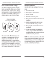
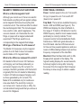
1
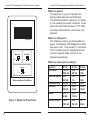
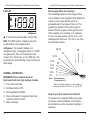
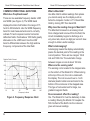
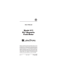
Lake Shore is a technology leader in the development of cryogenic temperature sensors, precision low temperature measurement and control instrumentation, and magnetic measurement and test systems. Since 1968, Lake Shore physicists, material scientists, and engineers have dedicated themselves to the development of tomorrow’s technology today. Lake Shore serves a worldwide network of Customers including university and national laboratories, as well as many of the premier companies around the world. User’s Manual Model 412 Electromagnetic Field Meter Lake Shore Cryotronics, Inc. 575 McCorkle Blvd. Westerville, Ohio 43082-8888 USA E-Mail Addresses: [email protected] [email protected] Visit Our Website: www.lakeshore.com Fax: (614) 891-1392 Phone: (614) 891-2243 Methods and apparatus disclosed and described herein have been developed solely on company funds of Lake Shore Cryotronics, Inc. No government or other contractual support or relationship whatsoever has existed which in any way affects or mitigates proprietary rights of Lake Shore Cryotronics, Inc. in these developments. Methods and apparatus disclosed herein may be subject to U.S. Patents existing or applied for. Lake Shore Cryotronics, Inc. reserves the right to add, improve, modify, or withdraw functions, design modifications, or products at any time without notice. Lake Shore shall not be liable for errors contained herein or for incidental or consequential damages in connection with furnishing, performance, or use of this material. Rev. 1.2 P/N 119-020 24 August 2004 Model 412 Electromagnetic Field Meter User’s Manual LIMITED WARRANTY STATEMENT – WARRANTY PERIOD: 1 YEAR 1. Lake Shore warrants that this Lake Shore product (the “Product”) will be free from defects in materials and workmanship for the Warranty Period specified above (the “Warranty Period”). If Lake Shore receives notice of any such defects during the Warranty Period and the Product is shipped freight prepaid, Lake Shore will, at its option, either repair or replace the Product if it is so defective without charge to the owner for parts, service labor or associated customary return shipping cost. Any such replacement for the Product may be either new or equivalent in performance to new. Replacement or repaired parts will be warranted for only the unexpired portion of the original warranty or 90 days (whichever is greater). 2. Lake Shore warrants the Product only if it has been sold by an authorized Lake Shore employee, sales representative, dealer or original equipment manufacturer (OEM). 3. The Product may contain remanufactured parts equivalent to new in performance or may have been subject to incidental use. 4. The Warranty Period begins on the date of delivery of the Product or later on the date of installation of the Product if the Product is installed by Lake Shore, provided that if you schedule or delay the Lake Shore installation for more than 30 days after delivery the Warranty Period begins on the 31st day after delivery. 5. This limited warranty does not apply to defects in the Product resulting from (a) improper or inadequate maintenance, repair or calibration, (b) fuses, software and nonrechargeable batteries, (c) software, interfacing, parts or other supplies not furnished by Lake Shore, (d) unauthorized modification or misuse, (e) operation outside of the published specifications or (f) improper site preparation or maintenance. 6. To the extent allowed by applicable law, the above warranties are exclusive and no other warranty or condition, whether written or oral, is expressed or implied. Lake shore specifically disclaims any implied warranties or conditions of merchantability, satisfactory quality and/or fitness for a particular purpose with respect to the product. Some countries, states or provinces do not allow limitations on an implied warranty, so the above limitation or exclusion might not apply to you. This warranty gives you specific legal rights and you might also have other rights that vary from country to country, state to state or province to province. 7. To the extent allowed by applicable law, the remedies in this warranty statement are your sole and exclusive remedies. 8. Except to the extent prohibited by applicable law, in no event will lake shore or any of its subsidiaries, affiliates or suppliers be liable for direct, special, incidental, consequential or other damages (including lost profit, lost data or downtime costs) arising out of the use, inability to use or result of use of the product, whether based in warranty, contract, tort or other legal theory, and whether or not lake shore has been advised of the possibility of such damages. Your use of the Product is entirely at your own risk. Some countries, states and provinces do not allow the exclusion of liability for incidental or consequential damages, so the above limitation may not apply to you. 9. Except to the extent allowed by applicable law, the terms of this limited warranty statement do not exclude, restrict or modify, and are in addition to, the mandatory statutory rights applicable to the sale of the product to you. Copyright © 1994, 1997, 1999, and 2004 by Lake Shore Cryotronics, Inc. All rights reserved. No portion of this manual may be reproduced, stored in a retrieval system, or transmitted, in any form or by any means, electronic, mechanical, photocopying, recording, or otherwise, without the express written permission of Lake Shore. A Model 412 Electromagnetic Field Meter User’s Manual BATTERY REPLACEMENT When the battery level falls below 5.5 volts, BAT appears in the display, indicating a low battery. About an hour measurement time remains before accuracy degrades. Replace the battery as soon as possible. To remove the battery, turn the Power switch OFF, turn the unit over, and use a small screwdriver to remove the bottom door in the enclosure. Carefully disconnect the old battery, connect a new battery, then replace the back cover. IN CASE OF TROUBLE If the instrument fails to turn on or behaves unpredictably, replace the battery. This usually solves most problems. There are no locally serviceable parts in the Model 412. If you are experiencing problems, contact the factory at the phone numbers or e-mail addresses on the back of this manual. To return a unit, obtain a Return Goods Authorization (RGA) number from a factory representative. Lake Shore requires the following information before attempting any repair: 1. Instrument model and serial number. 2. User name, company, address, and phone number. 3. Malfunction symptoms. 4. RGA number. Units ship to Lake Shore at Customer expense. Lake Shore pays shipping to return units under warranty. If possible, use original packing material for reshipment. If not available, consult Lake Shore for shipping and packing instructions. Model 412 Electromagnetic Field Meter User’s Manual SPECIFICATIONS Ranges: 199.9 mG, 1999 mG (Autoranging) Resolution: 0.1 mG on 199.9 mG Range; 1 mG on 1999 mG Range Accuracy: at 50/60 Hz – 1% ±1 digit typical, ±2 digits (<10 mG). See Figure 2 for accuracy at frequencies other than 60 Hz. Frequency Bands: Low Band: 15 Hz to 1000 Hz Wide Band: 15 Hz to 300,000 Hz Frequency Response (nominal): +5% band center; –25% band edges Max Hold Decay: <0.1% of range per second. Display: 3½-digit Liquid Crystal Display (LCD) Battery Type: 9-volt Alkaline Battery Battery Life: 100 hours Operating Temperature Range: 0 to +50 °C (32 to 122 °F) Dimensions: 15.2 × 8.3 × 3.6 cm (6 × 3.25 × 1.4 inches) Weight: 240 grams (0.52 lb.) with battery The unit is not waterproof. CERTIFICATION Lake Shore certifies that this product has been inspected and tested in accordance with its published specifications and that this product met its published specifications at the time of shipment. The accuracy and calibration of this product at the time of shipment are traceable to the United States National Institute of Standards and Technology (NIST); formerly known as the National Bureau of Standards (NBS). 12 Model 412 Electromagnetic Field Meter User’s Manual INTRODUCTION The Model 412 Electromagnetic Field Meter is a battery-powered, hand-held, instrument that measures magnetic fields around power lines, appliances, computers, and other electrical equipment. The easy to read display automatically switches to the measurement range offering the best resolution. The Model 412 has features not offered on other, similar detectors. This includes the ability to differentiate between high and low frequency components of a magnetic field. In the WIDE setting, the Model 412 covers many times the frequency bandwidth of other low cost AC magnetic field meters on the market. Another feature not usually offered is Max Hold, which allows retention of the highest reading long enough to take measurements that are outside the line-of-sight. Features • Hand-held, compact, and light weight • Autoranging (199.9 and 1999 mG) • 0.1 mG Resolution • Wide frequency response • Max Hold retains highest reading • Low Battery indicator • One year warranty 1 Model 412 Electromagnetic Field Meter User’s Manual Model 412 Electromagnetic Field Meter User’s Manual What is a gauss? The gauss (G) is a unit of magnetic flux density (often referred to as the B field). The dictionary defines a gauss as 10 teslas, or one maxwell per square centimeter. It was named for Karl Fredrich Gauss (1777-1855) a German mathematician, astronomer, and physicist. –4 ���������� �������� ��� ��������� �� ��� ���� ����� ��� �� ��������������������������� Figure 1. Model 412 Front Panel 2 What is a milligauss? The milligauss (mG) is one-thousandth of a gauss. It would take 1000 milligauss to make one gauss. Also, 1 mG equals 0.1 microtesla. This is a better scale for measuring the low level AC magnetic fields common to our ambient surroundings. What are some typical readings? Appliance Can Opener At 4 in. 1300 to 4000 mG Computer Monitor 50 to 600 mG Microwave Oven 600 mG Television 5 to 100 mG Toaster 10 to 60 mG Vacuum Cleaner 230 to 1300 mG At 12 in. 30 to 300 mG 3 to 3 to 90 mG 0.4 to 20 mG 0.6 to 7.0 mG 20 to 200 mG At 36 in. 0.5 to 7 mG <1 to 2 mG 5 mG <0.1 to 1.5 mG <0.1 mG 1 to 20 mG 11 Model 412 Electromagnetic Field Meter User’s Manual Model 412 Electromagnetic Field Meter User’s Manual MAGNETIC TERMINOLOGY QUESTIONS FRONT PANEL CONTROLS What is an Electromagnetic Field? Although you cannot see it, there is an electric field around everything with an applied voltage, and a magnetic field around everything that conducts current. The combined effect is called the electromagnetic field. This includes power lines, electric cords, electric appliances, TVs, vacuum cleaners, etc. Remember the iron filings on paper with a magnet underneath experiment? The filings would line up corresponding to the magnetic field shape. What type of field does the 412 measure? Power. Controls power to the unit. Turn switch On (up) to power the unit. Turn switch Off (down) to turn power off. The Model 412 measures only the magnetic portion of an AC field. It does not measure electric fields or DC magnetic fields. What is the difference between DC and AC? DC stands for Direct Current. DC fields are unchanging, such as those produced by a permanent magnet or by DC currents. For example, the Earth generates a DC field which is typically 500 mG. AC stands for Alternating Current. AC fields are always changing, such as those generated by AC currents. The Model 412 is calibrated only for continuous sine wave fields. The electricity running to our homes is AC. Inside a home or office, the normal ambient background that you will see is around 0.4 milligauss. 10 Freq Band. There are two available frequency bands: LOW and WIDE (see Figure 2). The WIDE band displays the total of all fields in the range of 15 hertz to 300 kilohertz. Use the WIDE frequency band for most measurements, particularly to correctly indicate TV and computer monitor horizontal deflection fields. Fields above 1000 hertz great attenuate on the LOW band. Use the LOW band around AC line and line powered appliances and as a means of differentiating between high and low frequency components of the total field. Max Hold. When the Max Hold switch is ON, the s symbol appears in the display. The highest reading displays for several seconds, but slowly begins to decay after removing the sensor from the magnetic field. However, the decay is slow enough to obtain a usable reading. 3 Model 412 Electromagnetic Field Meter User’s Manual DISPLAY Does angle affect the reading? ��� ���������� s This symbol indicates Max Hold is ON. BAT. The BAT symbol displays when the 9 volt battery needs replacement. milligauss. The numeric display is in milligauss (mG). A milligauss (mG) is 1/1000th of a gauss (G). The unit measures in two ranges: 0 to 199.9 mG, or 0 to 1999 mG. The decimal point automatically moves to the best field range. NORMAL OPERATION WARNING: Never extend hands or instrument into live high voltage circuits. 1. Turn instrument ON. 2. Set Max Hold to OFF. 3. Set Freq Band to WIDE. 4. Place instrument in magnetic field, then hold the instrument still. 5. Take a reading. 4 Model 412 Electromagnetic Field Meter User’s Manual Yes. Readings depend on the angle of the coil in relation to the magnetic field. Maximum output occurs when the flux vector is perpendicular to the plane of the coil. The greater the deviation from right angles in either of the three axes, the larger the error of the reading. For example, a 5° variance on any one axis causes a 0.4% error, a 10° misalignment induces a 1.5% error, etc. See the illustration below. ����� ����� ��� � ��� ���� ��� ���� ��� ���� ��� ���� �� �� �� ����� �������������� ���������������θ� ��������������������������������������������� ���������������������������������������θ������ How do you test spaces & locations? To measure the magnetic field at any point of interest, rotate the Model 412 slowly to all orientations until a maximum reading is obtained. 9 Model 412 Electromagnetic Field Meter User’s Manual Model 412 Electromagnetic Field Meter User’s Manual Does orientation affect the reading? MAX HOLD OPERATION Yes. When investigating unknown magnetic fields, check all three spatial axes to arrive at the maximum field. As shown below, placing the Model 412 in front of a TV screen (with the Freq Band switch in WIDE position) gives a different reading in each of the three axes. Use Max Hold to take readings in hard to see areas. ��������������������� ������������������������� 1. Turn instrument ON. 2. Allow display to settle near zero. 3. Set Max Hold ON. 4. Select the desired Freq Band. 5. Slowly place the instrument in the field to be measured. 6. Hold the instrument in the field for a few seconds to allow the display to settle. 7. Slowly bring the instrument back and view the reading. ������� ������� ������ The reason for the different readings is the orientation of the measurement coil in the stepped area of the Model 412. The coil responds most strongly to a magnetic field running perpendicular through the coil (see the arrows in the above illustration.) Turning the Model 412 to each of the three axes orients the coil for taking measurements in each plane. 8 8. To reset the instrument and take another reading, simply turn MAX HOLD OFF, let the display settle, then turn MAX HOLD ON and follow the same procedure. NOTE: It is not recommended to use Max Hold at field levels below 50 milligauss. Motion in the earth’s field can give erroneous readings. Also, a possible error of about 4 milligauss can occur at switch-on of the Max Hold feature. 5 Model 412 Electromagnetic Field Meter User’s Manual Model 412 Electromagnetic Field Meter User’s Manual COMMON OPERATIONAL QUESTIONS What does Freq Band mean? There are two available frequency bands: LOW and WIDE (see Figure 2). The WIDE band displays the total of all fields in the range of 15 hertz to 300 kilohertz. Use the WIDE frequency band for most measurements and to correctly indicate TV and computer monitor horizontal deflection fields. Fields above 1000 hertz greatly attenuate on the LOW band. Use the LOW band to differentiate between the high and low frequency components of the total field. ������������������������� ��� ��� �� �� �� ��� ���� ���� ���� �� � �� ��� ��� �� ������������������ ���� Figure 2. Frequency Response Chart 6 �� What is Max Hold? Use Max Hold to obtain readings from places you cannot easily see the display such as behind a computer monitor or TV. Reset Max Hold by turning OFF then back ON. Why does the reading change in Max Hold? The Max Hold is based on an analog circuit. Once charged and removed from the field, the circuit immediately begins to discharge at a very slow rate, about one digit per second: slow enough to obtain useful readings. What is Autoranging? Autoranging means the display automatically places the decimal point of the reading in the correct position. There are two ranges: 199.9 mG and 1999 mG. The automatic change between ranges occurs at about 160 mG. Where are the sensing coils? The sensing coil is located in the stepped area on the bottom of the Model 412. When looking at the top of the unit, the coil is underneath the display. The coil is wound over a 1-inch diameter plastic bobbin and anchored to the bottom of the enclosure in the stepped area. This type of coil works best for large, low gradient magnetic fields. Does movement affect the reading? Yes. The Model 412 must be stationary to take a reading. Moving the Model 412 couples the 500 mG field of the Earth into the coils and gives erroneous readings. 7 Model 412 Electromagnetic Field Meter User’s Manual Model 412 Electromagnetic Field Meter User’s Manual COMMON OPERATIONAL QUESTIONS What does Freq Band mean? There are two available frequency bands: LOW and WIDE (see Figure 2). The WIDE band displays the total of all fields in the range of 15 hertz to 300 kilohertz. Use the WIDE frequency band for most measurements and to correctly indicate TV and computer monitor horizontal deflection fields. Fields above 1000 hertz greatly attenuate on the LOW band. Use the LOW band to differentiate between the high and low frequency components of the total field. ������������������������� ��� ��� �� �� �� ��� ���� ���� ���� �� � �� ��� ��� �� ������������������ ���� Figure 2. Frequency Response Chart 6 �� What is Max Hold? Use Max Hold to obtain readings from places you cannot easily see the display such as behind a computer monitor or TV. Reset Max Hold by turning OFF then back ON. Why does the reading change in Max Hold? The Max Hold is based on an analog circuit. Once charged and removed from the field, the circuit immediately begins to discharge at a very slow rate, about one digit per second: slow enough to obtain useful readings. What is Autoranging? Autoranging means the display automatically places the decimal point of the reading in the correct position. There are two ranges: 199.9 mG and 1999 mG. The automatic change between ranges occurs at about 160 mG. Where are the sensing coils? The sensing coil is located in the stepped area on the bottom of the Model 412. When looking at the top of the unit, the coil is underneath the display. The coil is wound over a 1-inch diameter plastic bobbin and anchored to the bottom of the enclosure in the stepped area. This type of coil works best for large, low gradient magnetic fields. Does movement affect the reading? Yes. The Model 412 must be stationary to take a reading. Moving the Model 412 couples the 500 mG field of the Earth into the coils and gives erroneous readings. 7 Model 412 Electromagnetic Field Meter User’s Manual Model 412 Electromagnetic Field Meter User’s Manual Does orientation affect the reading? MAX HOLD OPERATION Yes. When investigating unknown magnetic fields, check all three spatial axes to arrive at the maximum field. As shown below, placing the Model 412 in front of a TV screen (with the Freq Band switch in WIDE position) gives a different reading in each of the three axes. Use Max Hold to take readings in hard to see areas. ��������������������� ������������������������� 1. Turn instrument ON. 2. Allow display to settle near zero. 3. Set Max Hold ON. 4. Select the desired Freq Band. 5. Slowly place the instrument in the field to be measured. 6. Hold the instrument in the field for a few seconds to allow the display to settle. 7. Slowly bring the instrument back and view the reading. ������� ������� ������ The reason for the different readings is the orientation of the measurement coil in the stepped area of the Model 412. The coil responds most strongly to a magnetic field running perpendicular through the coil (see the arrows in the above illustration.) Turning the Model 412 to each of the three axes orients the coil for taking measurements in each plane. 8 8. To reset the instrument and take another reading, simply turn MAX HOLD OFF, let the display settle, then turn MAX HOLD ON and follow the same procedure. NOTE: It is not recommended to use Max Hold at field levels below 50 milligauss. Motion in the earth’s field can give erroneous readings. Also, a possible error of about 4 milligauss can occur at switch-on of the Max Hold feature. 5 Model 412 Electromagnetic Field Meter User’s Manual DISPLAY Does angle affect the reading? ��� ���������� s This symbol indicates Max Hold is ON. BAT. The BAT symbol displays when the 9 volt battery needs replacement. milligauss. The numeric display is in milligauss (mG). A milligauss (mG) is 1/1000th of a gauss (G). The unit measures in two ranges: 0 to 199.9 mG, or 0 to 1999 mG. The decimal point automatically moves to the best field range. NORMAL OPERATION WARNING: Never extend hands or instrument into live high voltage circuits. 1. Turn instrument ON. 2. Set Max Hold to OFF. 3. Set Freq Band to WIDE. 4. Place instrument in magnetic field, then hold the instrument still. 5. Take a reading. 4 Model 412 Electromagnetic Field Meter User’s Manual Yes. Readings depend on the angle of the coil in relation to the magnetic field. Maximum output occurs when the flux vector is perpendicular to the plane of the coil. The greater the deviation from right angles in either of the three axes, the larger the error of the reading. For example, a 5° variance on any one axis causes a 0.4% error, a 10° misalignment induces a 1.5% error, etc. See the illustration below. ����� ����� ��� � ��� ���� ��� ���� ��� ���� ��� ���� �� �� �� ����� �������������� ���������������θ� ��������������������������������������������� ���������������������������������������θ������ How do you test spaces & locations? To measure the magnetic field at any point of interest, rotate the Model 412 slowly to all orientations until a maximum reading is obtained. 9 Model 412 Electromagnetic Field Meter User’s Manual Model 412 Electromagnetic Field Meter User’s Manual MAGNETIC TERMINOLOGY QUESTIONS FRONT PANEL CONTROLS What is an Electromagnetic Field? Although you cannot see it, there is an electric field around everything with an applied voltage, and a magnetic field around everything that conducts current. The combined effect is called the electromagnetic field. This includes power lines, electric cords, electric appliances, TVs, vacuum cleaners, etc. Remember the iron filings on paper with a magnet underneath experiment? The filings would line up corresponding to the magnetic field shape. What type of field does the 412 measure? Power. Controls power to the unit. Turn switch On (up) to power the unit. Turn switch Off (down) to turn power off. The Model 412 measures only the magnetic portion of an AC field. It does not measure electric fields or DC magnetic fields. What is the difference between DC and AC? DC stands for Direct Current. DC fields are unchanging, such as those produced by a permanent magnet or by DC currents. For example, the Earth generates a DC field which is typically 500 mG. AC stands for Alternating Current. AC fields are always changing, such as those generated by AC currents. The Model 412 is calibrated only for continuous sine wave fields. The electricity running to our homes is AC. Inside a home or office, the normal ambient background that you will see is around 0.4 milligauss. 10 Freq Band. There are two available frequency bands: LOW and WIDE (see Figure 2). The WIDE band displays the total of all fields in the range of 15 hertz to 300 kilohertz. Use the WIDE frequency band for most measurements, particularly to correctly indicate TV and computer monitor horizontal deflection fields. Fields above 1000 hertz great attenuate on the LOW band. Use the LOW band around AC line and line powered appliances and as a means of differentiating between high and low frequency components of the total field. Max Hold. When the Max Hold switch is ON, the s symbol appears in the display. The highest reading displays for several seconds, but slowly begins to decay after removing the sensor from the magnetic field. However, the decay is slow enough to obtain a usable reading. 3 Model 412 Electromagnetic Field Meter User’s Manual Model 412 Electromagnetic Field Meter User’s Manual What is a gauss? The gauss (G) is a unit of magnetic flux density (often referred to as the B field). The dictionary defines a gauss as 10 teslas, or one maxwell per square centimeter. It was named for Karl Fredrich Gauss (1777-1855) a German mathematician, astronomer, and physicist. –4 ���������� �������� ��� ��������� �� ��� ���� ����� ��� �� ��������������������������� Figure 1. Model 412 Front Panel 2 What is a milligauss? The milligauss (mG) is one-thousandth of a gauss. It would take 1000 milligauss to make one gauss. Also, 1 mG equals 0.1 microtesla. This is a better scale for measuring the low level AC magnetic fields common to our ambient surroundings. What are some typical readings? Appliance Can Opener At 4 in. 1300 to 4000 mG Computer Monitor 50 to 600 mG Microwave Oven 600 mG Television 5 to 100 mG Toaster 10 to 60 mG Vacuum Cleaner 230 to 1300 mG At 12 in. 30 to 300 mG 3 to 3 to 90 mG 0.4 to 20 mG 0.6 to 7.0 mG 20 to 200 mG At 36 in. 0.5 to 7 mG <1 to 2 mG 5 mG <0.1 to 1.5 mG <0.1 mG 1 to 20 mG 11 Model 412 Electromagnetic Field Meter User’s Manual SPECIFICATIONS Ranges: 199.9 mG, 1999 mG (Autoranging) Resolution: 0.1 mG on 199.9 mG Range; 1 mG on 1999 mG Range Accuracy: at 50/60 Hz – 1% ±1 digit typical, ±2 digits (<10 mG). See Figure 2 for accuracy at frequencies other than 60 Hz. Frequency Bands: Low Band: 15 Hz to 1000 Hz Wide Band: 15 Hz to 300,000 Hz Frequency Response (nominal): +5% band center; –25% band edges Max Hold Decay: <0.1% of range per second. Display: 3½-digit Liquid Crystal Display (LCD) Battery Type: 9-volt Alkaline Battery Battery Life: 100 hours Operating Temperature Range: 0 to +50 °C (32 to 122 °F) Dimensions: 15.2 × 8.3 × 3.6 cm (6 × 3.25 × 1.4 inches) Weight: 240 grams (0.52 lb.) with battery The unit is not waterproof. CERTIFICATION Lake Shore certifies that this product has been inspected and tested in accordance with its published specifications and that this product met its published specifications at the time of shipment. The accuracy and calibration of this product at the time of shipment are traceable to the United States National Institute of Standards and Technology (NIST); formerly known as the National Bureau of Standards (NBS). 12 Model 412 Electromagnetic Field Meter User’s Manual INTRODUCTION The Model 412 Electromagnetic Field Meter is a battery-powered, hand-held, instrument that measures magnetic fields around power lines, appliances, computers, and other electrical equipment. The easy to read display automatically switches to the measurement range offering the best resolution. The Model 412 has features not offered on other, similar detectors. This includes the ability to differentiate between high and low frequency components of a magnetic field. In the WIDE setting, the Model 412 covers many times the frequency bandwidth of other low cost AC magnetic field meters on the market. Another feature not usually offered is Max Hold, which allows retention of the highest reading long enough to take measurements that are outside the line-of-sight. Features • Hand-held, compact, and light weight • Autoranging (199.9 and 1999 mG) • 0.1 mG Resolution • Wide frequency response • Max Hold retains highest reading • Low Battery indicator • One year warranty 1 Model 412 Electromagnetic Field Meter User’s Manual LIMITED WARRANTY STATEMENT – WARRANTY PERIOD: 1 YEAR 1. Lake Shore warrants that this Lake Shore product (the “Product”) will be free from defects in materials and workmanship for the Warranty Period specified above (the “Warranty Period”). If Lake Shore receives notice of any such defects during the Warranty Period and the Product is shipped freight prepaid, Lake Shore will, at its option, either repair or replace the Product if it is so defective without charge to the owner for parts, service labor or associated customary return shipping cost. Any such replacement for the Product may be either new or equivalent in performance to new. Replacement or repaired parts will be warranted for only the unexpired portion of the original warranty or 90 days (whichever is greater). 2. Lake Shore warrants the Product only if it has been sold by an authorized Lake Shore employee, sales representative, dealer or original equipment manufacturer (OEM). 3. The Product may contain remanufactured parts equivalent to new in performance or may have been subject to incidental use. 4. The Warranty Period begins on the date of delivery of the Product or later on the date of installation of the Product if the Product is installed by Lake Shore, provided that if you schedule or delay the Lake Shore installation for more than 30 days after delivery the Warranty Period begins on the 31st day after delivery. 5. This limited warranty does not apply to defects in the Product resulting from (a) improper or inadequate maintenance, repair or calibration, (b) fuses, software and nonrechargeable batteries, (c) software, interfacing, parts or other supplies not furnished by Lake Shore, (d) unauthorized modification or misuse, (e) operation outside of the published specifications or (f) improper site preparation or maintenance. 6. To the extent allowed by applicable law, the above warranties are exclusive and no other warranty or condition, whether written or oral, is expressed or implied. Lake shore specifically disclaims any implied warranties or conditions of merchantability, satisfactory quality and/or fitness for a particular purpose with respect to the product. Some countries, states or provinces do not allow limitations on an implied warranty, so the above limitation or exclusion might not apply to you. This warranty gives you specific legal rights and you might also have other rights that vary from country to country, state to state or province to province. 7. To the extent allowed by applicable law, the remedies in this warranty statement are your sole and exclusive remedies. 8. Except to the extent prohibited by applicable law, in no event will lake shore or any of its subsidiaries, affiliates or suppliers be liable for direct, special, incidental, consequential or other damages (including lost profit, lost data or downtime costs) arising out of the use, inability to use or result of use of the product, whether based in warranty, contract, tort or other legal theory, and whether or not lake shore has been advised of the possibility of such damages. Your use of the Product is entirely at your own risk. Some countries, states and provinces do not allow the exclusion of liability for incidental or consequential damages, so the above limitation may not apply to you. 9. Except to the extent allowed by applicable law, the terms of this limited warranty statement do not exclude, restrict or modify, and are in addition to, the mandatory statutory rights applicable to the sale of the product to you. Copyright © 1994, 1997, 1999, and 2004 by Lake Shore Cryotronics, Inc. All rights reserved. No portion of this manual may be reproduced, stored in a retrieval system, or transmitted, in any form or by any means, electronic, mechanical, photocopying, recording, or otherwise, without the express written permission of Lake Shore. A Model 412 Electromagnetic Field Meter User’s Manual BATTERY REPLACEMENT When the battery level falls below 5.5 volts, BAT appears in the display, indicating a low battery. About an hour measurement time remains before accuracy degrades. Replace the battery as soon as possible. To remove the battery, turn the Power switch OFF, turn the unit over, and use a small screwdriver to remove the bottom door in the enclosure. Carefully disconnect the old battery, connect a new battery, then replace the back cover. IN CASE OF TROUBLE If the instrument fails to turn on or behaves unpredictably, replace the battery. This usually solves most problems. There are no locally serviceable parts in the Model 412. If you are experiencing problems, contact the factory at the phone numbers or e-mail addresses on the back of this manual. To return a unit, obtain a Return Goods Authorization (RGA) number from a factory representative. Lake Shore requires the following information before attempting any repair: 1. Instrument model and serial number. 2. User name, company, address, and phone number. 3. Malfunction symptoms. 4. RGA number. Units ship to Lake Shore at Customer expense. Lake Shore pays shipping to return units under warranty. If possible, use original packing material for reshipment. If not available, consult Lake Shore for shipping and packing instructions. Lake Shore is a technology leader in the development of cryogenic temperature sensors, precision low temperature measurement and control instrumentation, and magnetic measurement and test systems. Since 1968, Lake Shore physicists, material scientists, and engineers have dedicated themselves to the development of tomorrow’s technology today. Lake Shore serves a worldwide network of Customers including university and national laboratories, as well as many of the premier companies around the world. User’s Manual Model 412 Electromagnetic Field Meter Lake Shore Cryotronics, Inc. 575 McCorkle Blvd. Westerville, Ohio 43082-8888 USA E-Mail Addresses: [email protected] [email protected] Visit Our Website: www.lakeshore.com Fax: (614) 891-1392 Phone: (614) 891-2243 Methods and apparatus disclosed and described herein have been developed solely on company funds of Lake Shore Cryotronics, Inc. No government or other contractual support or relationship whatsoever has existed which in any way affects or mitigates proprietary rights of Lake Shore Cryotronics, Inc. in these developments. Methods and apparatus disclosed herein may be subject to U.S. Patents existing or applied for. Lake Shore Cryotronics, Inc. reserves the right to add, improve, modify, or withdraw functions, design modifications, or products at any time without notice. Lake Shore shall not be liable for errors contained herein or for incidental or consequential damages in connection with furnishing, performance, or use of this material. Rev. 1.2 P/N 119-020 24 August 2004