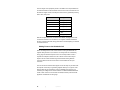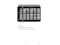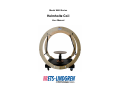
1
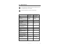
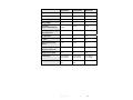
Model 6400 Series
Helmholtz Coil
User Manual
ETS-Lindgren L.P. reserves the right to make changes to any product described
herein in order to improve function, design, or for any other reason. Nothing
contained herein shall constitute ETS-Lindgren L.P. assuming any liability
whatsoever arising out of the application or use of any product or circuit
described herein. ETS-Lindgren L.P. does not convey any license under its
patent rights or the rights of others.
© Copyright 2001–2011 by ETS-Lindgren L.P. All Rights Reserved. No part
of this document may be copied by any means without written permission
from ETS-Lindgren L.P.
Trademarks used in this document: The ETS-Lindgren logo is a trademark of
ETS-Lindgren L.P.
Revision Record | 6400 Series Helmholtz, MANUAL | Part #399273, Rev. B
Revision
Description
Date
A
Initial Release
December, 2001
B
Updated title to reflect series.
June, 2009
Revise to current style standards.
Removed filter addendum, add
filter information as a numbered
section
C
Update table format in Section 3,
Specifications.
Update measurement in Section 5,
Operation from 2.45 cm to 2.54 cm
ii
|
April, 2011
Table of Contents
Notes, Cautions, and Warnings ............................................... iv 1.0 Introduction .......................................................................... 5 Model 6406S or Split Base Helmholtz Coils .................................................. 6 ETS-Lindgren Product Information Bulletin ................................................... 6 2.0 Maintenance ......................................................................... 7 Maintenance Recommendations ................................................................... 7 Annual Calibration ......................................................................................... 7 Service Procedures ....................................................................................... 7 3.0 Specifications....................................................................... 9 4.0 Theory of Operation........................................................... 13 5.0 Operation ............................................................................ 17 Helmholtz Coil Placement ............................................................................ 17 Helmholtz Coil EUT Table ........................................................................... 17 Adding Power to the Helmholtz Coil ............................................................ 18 Appendix A: Warranty ............................................................. 21 Appendix B: Conversion Table for Magnetic Units .............. 23 |
iii
Notes, Cautions, and Warnings
Note: Denotes helpful information intended to
provide tips for better use of the product.
Caution: Denotes a hazard. Failure to follow
instructions could result in minor personal injury
and/or property damage. Included text gives proper
procedures.
Warning: Denotes a hazard. Failure to follow
instructions could result in SEVERE personal injury
and/or property damage. Included text gives proper
procedures.
See the ETS-Lindgren Product Information Bulletin for safety,
regulatory, and other product marking information.
iv
|
1.0 Introduction
ETS-Lindgren Model 6400 Helmholtz Coils create an extremely uniform low
frequency magnetic field between and in the center of the coils. The generated
field can be applied as a magnetic field immunity test system or a low frequency
calibrator. The strength of the magnetic field generated is directly proportional to
the number of turns in the coils and the current applied to them. The coils are
wound in series so that the magnetic field produced by current flowing in one coil
aids the field in the other coil. The windings on all standard Helmholtz coils are
wound of insulated magnet wires. The wire gauge varies depending upon the
model of the coil system and details are found in the Specification section of this
manual. The maximum current of a custom Helmholtz coil is determined by the
wire gauge.
Several of the Helmholtz coils are equipped with a rotatable, adjustable-height
pedestal capable of supporting equipment under test (EUT) in the center of the
assembly base. Equipment which is exposed to the homogenous magnetic field
should be placed on the equipment test table with the height adjusted so that the
center of the equipment is closely aligned with the axis of the coils.
Ferromagnetic objects within the cylindrical volume of the coil tend to distort the
magnetic fields in areas near the object. The coil system has been constructed
with minimal metallic components limited to the copper conductors, the electrical
connectors and the caster frames. The casters, however, are outside of the coil
cylinder and cause practically no field disturbance.
Precision in the manufacture of the coils and their support assembly are well
within a design tolerance of 0.5 cm (0.2 in) in both radius and axial separation.
The limit of this tolerance would produce a maximum error of 0.55% in the
accuracy of the magnetic field constant under the worst conditions. For this
reason the Helmholtz coil is considered a standard and produces a magnetic
field whose accuracy is governed by the accuracy of the current monitoring
equipment.
Introduction
|
5
Model 6406S or Split Base Helmholtz Coils
A standard ETS-Lindgren Helmholtz coil consists of two identical circular coils
placed in parallel and spaced one radius apart. The coils are both mounted to a
single base with an adjustable pedestal placed in the center to position the EUT.
Some EUT’s, however, do not fit conveniently on the pedestal. In these instances
a split base option may be ordered. Each coil is mounted on a separate wheeled
base for positioning on either side of the EUT, such as an automobile.
The Model 6406S Helmholtz Coil consists of two coils secured on separate base
mounts in the Helmholtz configuration which can be used as a low frequency
calibrator. The coil provides a magnetic field which is essentially homogenous
throughout the volume of a 0.60 meter (2 foot) cylinder in its center. The coil
forms are rigidly supported by a nonmetallic, nonmagnetic framework. The
supplied cable assembly and proper orientation of the coils insures that the
Helmholtz coil system is arranged in the series-aiding configuration.
ETS-Lindgren Product Information Bulletin
See the ETS-Lindgren Product Information Bulletin included with your shipment
for the following:
6
•
Warranty information
•
Safety, regulatory, and other product marking information
•
Steps to receive your shipment
•
Steps to return a component for service
•
ETS-Lindgren calibration service
•
ETS-Lindgren contact information
|
Introduction
2.0 Maintenance
Before performing any maintenance, follow
the safety information in the ETS-Lindgren
Product Information Bulletin included with
your shipment.
Maintenance of the Helmholtz coil is limited
to external components such as cables or
connectors.
Clean the exterior of the coil using a damp
WARRANTY
cloth and mild cleaner. Always unplug the
unit before cleaning.
If you have any questions concerning
maintenance, contact ETS-Lindgren
Customer Service.
Maintenance Recommendations
Maintenance is limited to periodically cleaning the coil with a clean, damp cloth.
Annual Calibration
See the Product Information Bulletin included with your shipment for information
on ETS-Lindgren calibration services.
Service Procedures
For the steps to return a system or system component to ETS-Lindgren for
service, see the Product Information Bulletin included with your shipment.
Maintenance
|
7
This page intentionally left blank.
8
|
Maintenance
3.0 Specifications
Currents higher than the “Maximum Current Input” listed may be used
if the appropriate duty cycles are applied
See table in Appendix B for conversion to Gauss/Ampere
Model 6402
Model 6402M
Type
Mono-axial
Mono-axial
Coil Radius
30.5cm
30.5cm
(12.0 in)
(12.0 in)
Turns Per Coil
36
5
Gauge (AWG)
10
20
Coil Factor
(Amperes/Meter/Ampere)
84.3
11.14
1.06
0.14
R (Ohms DC)
0.5
0.7
L (mH)
3.5
70
Max Continuous Field
21.2
1.5
20
10
32
500
Coil Factor
(Gauss/Amperes)
(Gauss)
Max. Current Input
(Amperes Continuous)
Self Resonance (kHz)
Homogeneity
Mating Connector
±10% within a
±10% within a
19.8cm cylinder
25.4cm cylinder
MS3106, A-20-
BNC
09S
Specifications
|
9
Model 6403
Model 6404
Type
Mono-axial
Mono-axial
Coil Radius
45.7cm
60.9cm
(17.9 in)
(23.9 in)
Turns Per Coil
25
56
Gauge (AWG)
10
10
Coil Factor
39.79
65.25
0.50
0.83
R (Ohms DC)
2.5
1.5
L (mH)
40
19
Max Continuous Field
10
16.5
20
20
40
40
(Amperes/Meter/Ampere)
Coil Factor
(Gauss/Amperes)
(Gauss)
Max. Current Input
(Amperes Continuous)
Self Resonance (kHz)
Homogeneity
Mating Connector
10
|
±10% within a
±10% within a
23cm cylinder
40cm cylinder
MS3106, A-20-
MS3106, A-20-
23S
09S
Specifications
Model 6406
Model 6406S
Model 6408
Type
Mono-axial
Mono-axial
Mono-axial
Coil Radius
91.4cm
91.4cm
115.0cm
Turns Per Coil
64
110
64
Gauge (AWG)
10
6
10
86.04
39.79
0.63
1.08
0.50
R (Ohms DC)
2.5
1.7
3.0
L (mH)
45
100
64
Max Continuous Field
12.6
43.2
10
20
40
20
43
4
>10
Coil Factor
(Amperes/Meter/Ampere)
Coil Factor
50.06
(Gauss/Amperes)
(Gauss)
Max. Current Input
(Amperes Continuous)
Self Resonance (kHz)
Homogeneity
Mating Connector
±10% within a
±10% within a
±10% within a
0.6m cylinder
0.6m cylinder
0.7m cylinder
MS3106, A-24-
MS3106, A-24-
MS3106, A-24-09S
09S
09S
Specifications
|
11
This page intentionally left blank.
12
|
Specifications
4.0 Theory of Operation
Before operating any components, follow the
safety information in the ETS-Lindgren
Product Information Bulletin included with your
shipment.
The basic premise of a Helmholtz coil is that it produces a homogeneous
magnetic field in its center which is directly proportional to the number of turns in
the coils and the current applied to them. A Helmholtz coil is a parallel pair of
identical circular coils spaced one radius apart and wound so that the current
flows through both coils in the same direction. The winding results in a very
uniform magnetic field between the coils with the primary component parallel to
the axes of the two coils. The uniform field is the result of the addition of the two
field components parallel to the axes of the two coils and the difference between
the components perpendicular to the axes. The primary purpose of this device is
to provide a uniform, low frequency magnetic field for susceptibility testing of
electronic equipment.
The magnetic field strength (H) produced by a given AC or DC current
through the coil pair is given approximately by the formula
H ≈ 0.899
NI
R
• H is the magnetic field in oersteds
• N is the number of turns per coil
• I is the coil current in amperes
• R is the coil radius in centimeters
Theory of Operation
|
13
In SI Units, this becomes the formula where
H ≈ 0.715
NI
R
• H is the magnetic field in amperes per meter
• N is the number of turns per coil
• I is the coil current in amperes
• R is the coil radius in meters
If instead of magnetic field intensity (H) the magnetic flux density (B) is the
parameter of interest the equation, when expressed in CSG units,
becomes
B = μH ≈ 0.899 μ
NI
R
• B is the magnetic flux density in gauss
• µ is the relative permeability
• N is the number of turns per coil
• I is the coil current in amperes
• R is the coil radius in centimeters
14
|
Theory of Operation
In SI units, the relationship is given by
B = μμ 0 H ≈ 8.99 × 10 −7 μ
NI
R
• B is the magnetic flux density in teslas
• µ is the relative permeability
• µο is the permeability constant
• N is the number of turns per coil
• I is the coil current in amperes
• R is the coil radius in meters
For the unloaded coil, the relative permeability, µ, is one, so that
units, and
B = μ0 H in SI units.
B=H
in CGS
Refer to Appendix B: Conversion Table for Magnetic Units for more unit
conversions.
Theory of Operation
|
15
This page intentionally left blank.
16
|
Theory of Operation
5.0 Operation
Before operating any components, follow the safety
information in the ETS-Lindgren Product Information
Bulletin included with your shipment.
If high driving current is required at a high frequency,
take precautions to avoid shock or burn from the high
voltages developed across the reactive elements.
Helmholtz Coil Placement
Place the Helmholtz coil in a space relatively free of metal objects and structures.
This will insure a minimum of distortion and the best possible homogeneity of
magnetic fields within the test volume.
Push the coil assemblies into position by holding the coil section of
each assembly. Do not push the coil assemblies using the
thermoplastic support rods.
Helmholtz Coil EUT Table
For units equipped with an adjustable table, the table should be set at the desired
height before placing the test item on it. To adjust the table height, first loosen
the clamp screw(s) and then move the table height up or down to the desired
level. Hand-tighten the clamp screw(s). The table can be lifted off of the platform
to accommodate larger EUTs. Simply remove the plastic support screws on the
floor of the coil platform that attach the table and gently lift and remove the table.
The marks on the support column are spaced 2.54 cm(1 inch) apart
for reference. A mechanical stop limits the table travel within its lowest
and highest position.
The top of the table is within 2.54 cm (1 inch) of the coil system axis
when the lowermost inch mark is at the top of the base column.
Operation
|
17
Limit the weight of the equipment placed on the table to the coil specifications in
the chart that follows. Center the EUTs mass over the center of the base. Do not
lubricate the support column, but keep the column clean by periodically cleaning
with a clean, damp cloth.
Model
Weight Limit
6402
18 kg (40lb)
6402M
4.5 kg (10lb)
6403
18 kg (40 lb)
6404
34 kg (75 lb)
6406
34 kg (75 lb)
6406S
Split base, no
table
6408
34 kg (75 lb)
With the exception of the wire, connectors and casters (if equipped) the entire
coil structure is made of non-conductive, non-magnetic materials. Handle the
structure carefully at all times, taking precautions to avoid subjecting it to thermal
or mechanical shock.
Adding Power to the Helmholtz Coil
When connecting the AC or DC current source for driving the Helmholtz coil
magnetic field generator coil, be sure the connecting leads are of sufficiently
heavy gauge to handle the required current. For example, AWG 10 wire is
required for 20 amperes, based on a rule of thumb of 500 circular mils per
ampere. Also be certain that there is good mechanical bonding between
connecting leads to both the current source and the Helmholtz coil input
connector.
The coils are wound with #10 AWG copper wire so that they may be driven with
20 amperes continuously for generating magnetic fields up to 10 gauss. Lower
intensity fields may be generated by using a calibrated current supply or by
monitoring the voltage across a series resistor. The Models 6402M, 6406S and
certain custom coils are not wound with #10 AWG, therefore power should be
applied to correlate with the wire gauge.
18
|
Operation
Magnetic fields greater than one gauss may be generated at frequencies from
DC to 200 Hz. However, if higher frequencies are required, the coil impedance
will require fairly high driving voltages to drive enough current through the coil in
order to reach the desired field intensity. In certain cases, it may be necessary to
series resonate the coil if high driving current is required at a high frequency. If
this is the case, take precautions to avoid shock or burn from the high voltages
developed across the reactive elements.
Operation
|
19
This page intentionally left blank.
20
|
Operation
Appendix A: Warranty
See the Product Information Bulletin included with your shipment for
the complete ETS-Lindgren warranty for your Helmholtz Coil System.
DURATION OF WARRANTIES FOR A HELMHOLTZ COIL SYSTEM
All product warranties, except the warranty of title, and all remedies for warranty
failures are limited to two years.
Product Warranted
Duration of Warranty Period
Helmholtz Coil System
2 Years
Warranty
|
21
This page intentionally left blank.
22
|
Warranty
Appendix B: Conversion Table for Magnetic Units
To
To Convert From
Unit
System:
Magnetic
Quantity:
Units
SI (MKS)
tesla
1
ampturn/m
gauss
CGS
B
H
B
H
B
tesla
ampturn/m
-7†
4π x 10
gauss
oersted
gamma
10
1
79.57747
7.96 x 10
5‡
4
4π x 10
-3†
1
10
-4
10
‡
79.57747
1
oersted
10
4‡
4π x 10
-3
1
‡
gamma
10
9
4π x 10
2†
10
-4†
10
7.96 x 10
†
1
5
10
-9
5†
10
-5
10
-5‡
-4‡
1
Multiply by above value
†
Assumes μ = 1; if μ ≠1, multiply by value of μ to convert from H to B.
‡
Assumes μ = 1; if μ ≠1, divide by value of μ to convert from B to H.
2
1 tesla ≡ 1 weber/m .
For example,
4
1 tesla = 10 gauss.
1 gauss = 79.6 ampere-turns/m in an unloaded coil (μ = 1).
5
5
If μ = 2.50, 1 tesla = 7.96 x 10 / 2.50 = 3.18 x 10 amp-turns/m.
Conversion Table for Magnetic Units
|
23
This page intentionally left blank.
24
|
Conversion Table for Magnetic Units