1
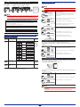
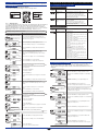
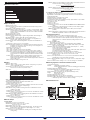
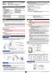
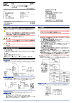
CHECKING THE PRODUCT SPECIFICATIONS AND THE CONTENTS OF THE PACKAGE
User’s
Manual
Model MVRK
Digital Limit Alarm (RTD Input Type)
with Active Color PV Display
(1) Model and Specifications Check
Check that the model and specifications indicated on the nameplate attached to the
side face of the main unit are as ordered. (In checking the model and suffix codes, refer
to the main specifications listed on the last page of this manual.)
IM 77J04R31-01E
(2) Contents of the Package
Check that the package contains the following items.
• MVRK: 1
• User’s manual (this manual: IM 77J04R31-01E): 1
Accessories:
• Tag number label: 1 sheet
• Range label: 1 sheet
• Spacer: 1 (used for DIN rail mounting)
Contents
1.
2.
3.
4.
NOTICE
MOUNTING METHODS
EXTERNAL WIRING
PART NAMES OF FRONT PANEL AND
THEIR FUNCTIONS
5. SWITCHING PARAMETERS
6. PARAMETER SETTING ORDER AND
PRECAUTIONS
7. SETTING INPUT-RELATED PARAMETERS
8. SETTING ALARM-RELATED PARAMETERS
9. INPUT ADJUSTMENTS
10. SETTING ACTIVE COLOR PV DISPLAY
11. OTHER PARAMETERS
12. MONITOR OUTPUT
13. TROUBLESHOOTING
14. MAIN SPECIFICATIONS
Keep this manual in a safe place.
IM 77J04R31-01E
Network Solutions Business Divisiion
2-9-32, Naka-cho Musashino-shi, Tokyo 180-8750 Japan
Phone: +81-422-52-7179 Facsimile: +81-422-52-6619
1st Edition : Aug. 2006 (YK)
1. NOTICE
3. EXTERNAL WIRING
This user’s manual should be carefully read before installing and operating the product.
The following symbol is used on the product and in this manual to ensure safe use.
WARNING
To avoid the risk of an electric shock, turn off the power supply and use a tester or
similar device to ensure that no power is supplied to a cable to be connected, before
carrying out wiring work.
This symbol is displayed on the product when it is necessary to refer to the user’s
manual for information on personnel and instrument safety. This symbol is displayed in
the user’s manual to indicate precautions for avoiding danger to the operator, such as
an electric shock.
CAUTION
• Use of the product ignoring the specifications may cause overheating or damage.
Before turning on the power, ensure the following:
(a) Power supply voltage and input signal value applied to the product should
meet the required specifications.
(b) The external wiring to the terminals and wiring to ground are as
specifications.
• Do not operate the product in the presence of flammable or explosive gases or
vapors. To do so is highly dangerous.
• If an inductance (L) load such as auxiliary relays or solenoid valves is used,
always insert a spark killer for diminishing sparks, such as a CR filter or a diode in
parallel with the inductance load. Otherwise a malfunction or relay failure may
occur. Refer to the following guidelines for a capacitor and resistor:
Capacitor: 0.5 to 1 µF with respect to a contact current of 1 A
Resistor: 0.5 to 1 Ω with respect to a contact voltage of 1 V
• Transfer contacts for 2 points of alarms consist of an NO contact and an NC
contact.
When using transfer contacts, consideration should be given to the risk of a short
circuit due to contact MBB*1 resulting from non-concurrent action of the NO and
NC contacts or to a short circuit caused by arcs produced when opening a contact
at large current.
*1 The condition where both NO and NC contacts close when the contact
actuates
• The power line and input/output signal lines should be installed away from noisegenerating sources. Otherwise accuracy cannot be guaranteed.
• The product is sensitive to static electricity; exercise care in operating it. Before
you operate the product, touch a nearby metal part to discharge static electricity.
The following symbols are used only in this manual.
IMPORTANT
Indicates that operating the hardware or software in a particular manner may cause
damage or result in a system failure.
NOTE
Draws attention to essential information for understanding the operations and/or
functions of the product.
2. MOUNTING METHODS
2.1 Wall Mounting
Unfasten the upper and lower stoppers to disconnect the main unit from the socket. Next,
anchor the socket onto the wall with two M4 screws. Then plug the main unit into the
socket and secure the main unit with the upper and lower stoppers.
Wiring should be connected to the terminals on the socket of the MVRK. The terminals for
external connections are of M3.5 screws. Use crimp-on lugs for connections to the
terminals.
It is recommended that signal wires have a nominal cross-sectional area of 0.5 mm2 or
thicker, while the power cable has a nominal cross-sectional area of 1.25 mm2 or thicker.
Make the wiring resistance of the input terminals 4 and 6 the same.
Stopper
• Mounting Dimensions
Unit: mm
Pitch: 56 or more
Main unit
2-ø4.5 or 2-M4
Mounting
screw
40±0.2 (16) 40±0.2
Power supply
7 L+
Socket
(SUPPLY)
Note:
• For side-by-side mounting, provide spacing of 5 mm or
more between the products.
• For DIN rail mounting, use the supplied spacer to
provide spacing of 5 mm between the products.
8 N–
(51)
(5 or more)
8
7
6
Input signal
5
RTD
4 A
4
2.2 DIN Rail Mounting
5 B
Locate the MVRK so that the DIN rail fits into the upper part of the DIN-rail groove at the
rear of the socket, and fasten the socket using the slide lock at the lower part of the
socket. For side-by-side mounting, attach the spacer supplied with the product to the DIN
rail to provide spacing between the products.
6 B
9
10 11
3
1
2
DIN rail
Fit into here
2 points of alarm outputs
4 points of alarm outputs
(Model code: MVRK-00 - 1
(Model code: MVRK-00 - 2
Relay
(Rear of the socket)
NO
NC
DIN rail
Relay
Push
(IN)
Spacer
Slide lock
10
11
COM
9
NO
2
NC
3
COM
1
)
Relay
Alarm-1
output
(ALM1)
Alarm-2
output
(ALM2)
NO
10
COM
Relay
9
NO
11
Relay
NO
2
COM
1
NO
3
Relay
)
Alarm-1output
(ALM1)
Alarm-4 output
(ALM4)
Alarm-2 output
(ALM2)
Alarm-3 output
(ALM3)
2.3 Using a Duct
Wiring for Monitor Output
When using a wiring duct, install the duct at least 30 mm away from the top and bottom
faces of the main unit.
If the monitor output code (one of 6, A or P) is specified at the time of order, the following
wiring is possible.
2.4 Installation Locations
Monitor output
• Avoid the following environments for installation locations:
Areas with vibration, corrosive gases, dust, water, oil, solvents, direct sunlight, radiation,
a strong electric field and/or a strong magnetic field
• If there is any risk of a surge being induced into the power line and/or signal lines due to
lightning or other factors, a dedicated lightning arrester should be used as protection for
both the product and a field-installed device.
RS-485
Analog output communication
+ 1
B+ 1
– 3
COM 3
A– 2
1
1
2
3
IM 77J04R31-01E 1st Edition : 2006.08.31-00
4. PART NAMES OF FRONT PANEL AND THEIR FUNCTIONS
Displays a measured value during operation.
PV (measured value)
Displays a parameter symbol when a parameter is set.
1 display
Displays an error code in the event of an error.
1 PV (measured value) display
2 DATA display
4 READY lamp
3 Alarm indicator lamp
2 points of alarms: 2 lamps
4 points of alarms: 4 lamps
5 SET/ENT key
Function
Part Name
Place for adhering
the tag number label
2 DATA display
Displays the setpoint of a variety of parameters.
Displays an alarm type in the event of an alarm. (Not displayed during normal operation.)
: High-limit alarm
: Low-limit alarm
: Other alarms
3 Alarm indicator lamp
In the event of an alarm, AL1 to AL4 (alarm 1 to alarm 4) light up.
4 READY lamp
Lights up when the power is turned on.
5 SET/ENT key
Used to switch parameter indication or accept a setpoint.
Pressing this key for more than 3 seconds allows you to select the Operation
Parameter Screen and Setup Parameter Screen alternately.
6 UP/DOWN key
Used to change the setpoint of a parameter.
7 Monitor output terminal
(option)
6 UP/DOWN key
NOTE
The front panel of the product is constructed to prevent opening.
Forcing it open will result in breakage.
7
Monitor output terminal
(Two-piece connector)
Pressing the
key increases a numerical value.
Pressing the
key decreases a numerical value.
Holding down a key accelerates the speed of change.
Outputs 1 to 5 V DC, 4 to 20 mA DC or RS-485 communication signal.
(To be added only when the monitor output has been specified at the time of
order.)
5. SWITCHING PARAMETERS
Power
ON
The
symbol indicates a reference chapter/section in this manual.
Operation Parameter Screen
Setup Parameter Screen 1
Setup Parameter Screen 2
Chapter 7
Range code No. (IN)
Sets the range code number (input type).
Chapter 8
Displays a measured value.
In this manual, this screen is called the "PV
(measured value) screen."
Alarm-1 action (AL1)
Sets the direction of alarm-1 action.
(See the Alarm Action Type Codes table in Section 8.1.)
Chapter 8
Alarm-2 action (AL2)
Sets the direction of alarm-2 action.
Chapter 8
Alarm-1 setpoint (A1)
Sets the alarm-1 setpoint.
B
(See the Alarm Action Type Codes table in Section 8.1.)
B is displayed when the monitor output (analog) has been specified.
Chapter 11
Measured input bias (BS)
This parameter is set to correct a measured
input value.
Chapter 8
Alarm-3 action (AL3)
(Displayed only for 4 points of alarms)
Sets the direction of alarm-3 action.
Chapter 8
Alarm-2 setpoint (A2)
Sets the alarm-2 setpoint.
(See the Alarm Action Type Codes table in Section 8.1.)
Chapter 8
Alarm-4 action (AL4)
(Displayed only for 4 points of alarms)
Sets the direction of alarm-4 action.
Chapter 8
Alarm-3 setpoint (A3)
(Displayed only for 4 points of alarms)
Sets the alarm-3 setpoint.
Chapter 10
PV display color mode (PCM)
Sets the Active color PV display.
(See the Alarm Action Type Codes table in Section 8.1.)
To the Setup Parameter Screen 1
Chapter 8
Alarm-4 setpoint (A4)
(Displayed only for 4 points of alarms)
Sets the alarm-4 setpoint.
Press this key for more than 3 sec.
NOTE
If the alarm action (AL1 to AL4) is set to "OFF," the relevant alarm
setpoint (A1 to A4) is not displayed.
A
Burnout action (BSL)
Sets the burnout action.
Chapter 8
Alarm-3 hysteresis (HY3)
(Displayed only for 4 points of alarms)
Sets the hysteresis of alarm 3.
Chapter 7
Wiring resistance correction (WIR)
Chapter 9
Input adjustment reset (RST)
Used to reset an input adjustment value.
Chapter 9
Input adjustment point LOW (BL)
Sets the reference value corresponding to
0% of the input when an input adjustment is
made.
Chapter 9
Input adjustment LOW (AL)
Adjusts the 0% value of an input.
A is displayed when the PV display color mode (PCM) has been set to 6, 7, 8 or 9.
Chapter 8
Alarm ON delay (OND)
A
Sets the condition monitoring time from the
establishment of alarm conditions to its
output.
Chapter 8
Alarm OFF delay (OFD)
Sets the condition monitoring time from the
establishment of return-to normal conditions
to its output.
Chapter 8
Setpoint (SP)
When using a deviation alarm, this
parameter is set to the value treated as the
reference for deviations.
Chapter 11
Key lock (LOC)
This parameter is set when change of parameter
settings (all parameters or parameters other than the
operation parameters) is locked to prevent wrong
operations.
Press this key
for more than 3 sec.
Chapter 9
Input adjustment point HIGH (BH)
Sets the reference value corresponding to
100% of the input when an input adjustment
is made.
Chapter 9
Input adjustment HIGH (AH)
Adjusts the 100% value of an input.
C
or
C is displayed
when the monitor
output (analog) has
been specified.
D
D is displayed when the
monitor output (RS-485
communication) has been
specified.
Press the DOWN key to display "-1"
on the DATA display and then press
the SET/ENT key.
To the Operation Parameter Screen
Press this key
for more than 3 sec.
C
Section 12.1
Visibility of monitor output adjustment screen (MON)
Sets the visibility of the screen for adjusting monitor
output. Pressing the SET/ENT key with "ON"
displayed on the DATA display causes the
adjustment screen to appear.
Section 12.1
Section 12.2
Parity (PRI)
Sets the parity.
Forced output of a monitor output value (MAN)
Used to force a value equivalent to -25% to +125%
of an analog output value to output, regardless of
input.
Section 12.2
Stop bit (STP)
Sets the stop bit.
Section 12.2
Data length (DLN)
Sets the data length.
Used when correcting wiring resistance.
To the Setup Parameter Screen 2
Section 12.2
Baud rate (BPS)
Sets the baud rate.
Chapter 7
Alarm-2 hysteresis (HY2)
Sets the hysteresis of alarm 2.
A
Section 12.2
Communication protocol (PSL)
Sets the communication protocol.
Section 12.2
Communication address (ADR)
Sets the communication address.
This parameter is set to extinguish the display
(not including the READY and alarm lamps) if no
keystroke is made for a specified time.
Chapter 8
Alarm-4 hysteresis (HY4)
(Displayed only for 4 points of alarms)
Sets the hysteresis of alarm 4.
To the Operation Parameter Screen
D
Section 12.1
Maximum monitor output value (RTH)
This parameter is set to treat any value as
the maximum output value with respect to
the input range.
Section 12.1
Minimum monitor output value (RTL)
This parameter is set to treat any value as
the minimum output value with respect to the
input range.
Economical mode time (ECO)
Chapter 8
Chapter 10
High limit for PV display color change (PCH)
Sets the high limit for PV limit mode or SP
deviation mode of Active color PV display.
Chapter 10
Low limit for PV display color change (PCL)
Sets the low limit for PV limit mode or SP
deviation mode of Active color PV display.
B
Chapter 11
Chapter 8
Alarm-1 hysteresis (HY1)
Sets the hysteresis of alarm 1.
Section 12.1
Monitor output zero adjustment (ZER)
Adjusts the zero point of the monitor output.
Section 12.1
Monitor output span adjustment (SPN)
Adjusts the span of the monitor output.
2
NOTE
If no keystroke is made for more than 2 minutes,
the PV screen automatically appears, regardless
of the parameter displayed. In this case, if a data
change is in progress (the decimal point is
blinking), the data being changed becomes invalid
and the PV screen appears with the previous data
displayed as is.
However, this action does not take place if the
parameter "MAN", "ZER" or "SPN" is being
displayed.
IM 77J04R31-01E 1st Edition : 2006.08.31-00
6. PARAMETER SETTING ORDER AND PRECAUTIONS
7.2 Setting Range Code No.
This section describes an example of setting the range code No. (IN) to “62” (instrument
input range: -199.9 to 200.0°C).
When setting a parameter, begin with Step 1 below and continue in sequence.
Range code No.
(IN)
Alarm-1 action Alarm-2 action Alarm-3 action Alarm-4 action
(AL1)
(AL2)
(AL3)
(AL4)
Step 2
Step 1
NOTE
After that, you
may proceed with
settings beginning
at any parameter.
Note that setting the range code No. (IN) to a value other than those specified in Section
7.1 is invalid.
When the power is turned on, the PV screen of the Operation
Parameter Screen appears.
Power ON
You can begin with any of these parameters.
Operation Parameter Screen
NOTE
If the settings for the range code No. (IN) or alarm actions (AL1 to AL4) are changed, the
relevant parameter setpoints shown in the table below will be initialized.
To change a parameter setpoint, begin with Step 1 above and continue in sequence.
Setup Parameter Screen 1
Parameters to be initialized if the range code No. (IN) is changed
Alarm setpoints (A1 to A4), hysteresis (HY1 to HY4), setpoint (SP)
Max. and min. monitor output values (RTH, RTL)
Input adjustment point LOW (BL) and HIGH (BH), input adjustment LOW (AL) and HIGH (AH),
wiring resistance correction (WIR)
High and low limits for PV display color change (PCH, PCL)
Press
to display "LOC." Press the SET/ENT key to display parameter "LOC."
Press
to display "-1." Press the DOWN key to display "-1" on the DATA display.
The decimal point blinks during
data change.
Press
Parameters to be initialized if the type of alarm action (AL1 to AL4) is changed
Press
Press
7. SETTING INPUT-RELATED PARAMETERS
Press
Setup Parameter Screen 2
Input type
Pt100
(ITS-90)
M range
H range
M range
H range
Instrument input range
Pt100
(IPTS-68)
JPt100
(JIS’89)
-199.9 to 200.0 °C
-199.9 to 660.0 °C
-199.9 to 200.0 °C
-199.9 to 510.0 °C
7.3 Setting Burnout Action
61
or
the range
code No.
specified at
the time of
oreder
This section describes an example of setting the burnout action to “UP.”
The procedure below begins with the condition in which the Setup Parameter Screen 2 is
displayed.
Setup Parameter Screen 2
Press
M range Pt50(JIS’81) -199.9 to 649.0 °C
Press
H range
to display "UP."
M range
H range
M range
H range
M range
Pt100
(ITS-90)
80.0 to 930.0 K
Pt100
(IPTS-68)
80.0 to 930.0 K
JPt100
(JIS’89)
80.0 to 780.0 K
M range Pt50(JIS’81)
Wiring resistance
correction
(WIR)
-199.9 to 660.0 °C
OFF (0), UP (1), DOWN (2)
OFF (0), ON (1)
Press the SET/ENT key again for more than 3 sec.
This causes the Operation Parameter Screen to appear.
fore more than
3 sec.
To the Operation Parameter Screen
-199.9 to 190.0 °C
M range
Burnout action
(BSL)
Factory-Set
Value
Setting Range
H range
Press the SET/ENT key to accept range code No. "62."
This completes the process for setting the range code No.
.
This completes the process for
setting the range code No.
7.1 Setting Ranges and Factory-Set Values of Input-Related Parameters
Range code No.
Press the UP or DOWN key to display "62" on the DATA display.
The decimal point blinks during
data change.
High and low limits for PV display color change (PCH, PCL)
Range code No.
(IN)
Step 1
or
to display "62."
Parameters to be initialized if the type of PV display color mode (PCM) is changed
Parameter Name
Press the SET/ENT key to display parameter "IN" for setting the
range code No. in the Setup Parameter Screen 2.
.
Setup Parameter Screen 2
The alarm setpoint (A1 to A4) corresponding to each alarm action (AL1 to AL4)
(Example: If AL1 is changed, A1 will be initialized.)
Parameter
Symbol
When you press the SET/ENT key for more than 3 sec. with the
Operation Parameter Screen displayed, the Setup Parameter
Screen 1 appears.
Press this key for
more than 3 sec.
80.0 to 470.0 K
to display "BSL."
or
Press the SET/ENT key to display parameter "BSL."
Press the UP or DOWN key to display "UP" on the DATA display.
The decimal point blinks during
data change.
Press
80.0 to 470.0 K
Press the SET/ENT key to accept burnout "UP."
This completes the process for setting the burnout action.
.
This completes the process for
setting the burnout action.
80.0 to 460.0 K
80.0 to 920.0 K
7.4 Correcting Wiring Resistance
This section describes how to correct wiring resistance when an error occurs due to the
influence of the input wiring resistance.
Correct wiring resistance after completing the wiring.
According to
the suffix
codes specified
at the time of
order
OFF
Note: When used with BARD-700, use the H range.
Ranges other than H range cannot be used for BARD-700.
A
4
B
5
B
6
MVRK
Short-circuit at the cable end.
The procedure below begins with the condition in which the Setup Parameter Screen 2 is
displayed.
Setup Parameter Screen 2
Press
to display "WIR."
Press
Press the SET/ENT key to display parameter "WIR."
or
to display "ON."
Press the UP or DOWN key to display "ON" on the DATA display.
The decimal point blinks during
data change.
Press
.
Press the SET/ENT key to correct the wiring resistance.
This completes the process for
correcting the wiring resistance.
NOTE
If the burnout action setting is changed, the wiring resistance correction is automatically
set to OFF (0).
Correct the wiring resistance again after changing the burnout action setting.
3
IM 77J04R31-01E 1st Edition : 2006.08.31-00
8. SETTING ALARM-RELATED PARAMETERS
8.2 Setting Alarm Output-Related Parameters
This section describes an example of setting the alarm-1 action (AL1) to “12” (PV low-limit
alarm, with stand-by action), alarm-1 setpoint (A1) to “0” (°C), alarm-1 hysteresis 1 (HY1)
to “5” (°C), alarm ON delay (OND) to “5” (sec.) and alarm OFF delay (OFD) to “5” (sec.)
with the range code No. (IN) set to “62” (instrument input range: -199.9 to 200.0°C).
(Parameters relating to alarm 2 to alarm 4 can be set in the same way as the procedure
below.)
8.1 Setting Ranges and Factory-Set Values of Alarm-Related Parameters
The followings are the factory-set values for the range code No. 61.
They may differ depending on the range code No. specified at the time of order.
Operation Parameter Screen
Parameter
Symbol
Parameter Name
Factory-Set
Value
Setting Range
Alarm-1 setpoint
(A1)
Within the instrument input range.
Operation Parameter Screen
20.0
Alarm-2 setpoint
(A2)
2 points of alarms: 80.0
4 points of alarms: 30.0
Alarm-3 setpoint
(A3)
70.0
Alarm-4 setpoint
(A4)
80.0
When the power is turned on, the PV screen of the
Operation Parameter Screen appears.
Power ON
Press this key for
more than 3 sec.
Setup Parameter Screen 1
Press
Step 2
Parameter Name
Setting Range
Alarm-1 action
(AL1)
See the Alarm Action Type Codes table.
Alarm-3 action
(AL3)
1
Alarm-4 action
(AL4)
1
The value resulting from adding a hysteresis value
to an alarm setpoint should be within the
instrument input range.
This completes the process for
setting the alarm-1 action.
Press
Alarm-4 Hysteresis
(HY4)
3.0
Setting range: 0 to 999 sec.
Setting resolution: 1 sec.
0
Alarm OFF delay
(OFD)
Setting range: 0 to 999 sec.
Setting resolution: 1 sec.
0
Setpoint
(SP)
Within the instrument input range.
to display "A1." Press the SET/ENT key to display parameter "A1."
Press
or
Press the UP or DOWN key to display a low-limit alarm
value "0.0" (°C) that is set to the DATA display.
The decimal point blinks during
data change.
Press
Press the SET/ENT key to accept low-limit alarm "0.0"
(°C).
.
This completes the process for
setting the alarm-1 setpoint.
Setup Parameter Screen 1
Minimum
value of the
instrument
input range
Press the UP or DOWN key to display "5.0" (°C) on the
DATA display.
Press
or
to display "5.0."
The decimal point blinks during
data change.
<Alarm Action Type Codes>
Press
Alarm Action Type Code
Without Stand-by
Action
Alarm Type
Deenergized
under
Normal
Condition
Alarm Action
With Stand-by
Action
Energized Deunder
energized
Normal under
Condition Normal
Condition
This completes the process for
setting the alarm-1 hysteresis.
Energized
under
Normal
Condition
Press
"OND."
or
to display "5."
Alarm
Press the SET/ENT key to display parameter "OND."
Press the UP or DOWN key to display "5" (sec.) on the
DATA display.
Press
Normal
PV
to display
The decimal point blinks during
data change.
Alarm setpoint
Press
Hysteresis
PV low-limit
alarm
Alarm
PV
.
This completes the process for
setting the alarm ON delay.
Press the SET/ENT key again to display parameter
"OFD."
Normal
Press
Press the SET/ENT key to accept alarm ON delay "5"
(sec).
.
Setting the alarm ON delay
Hysteresis
PV high-limit
alarm
Press the SET/ENT key to accept alarm-1 hysteresis "5.0"
(°C).
.
Setting the hysteresis
Alarm ON delay
(OND)
Press
to display "0.0."
3.0
3.0
for more
than 3 sec.
Then to set the alarm setpoint, press the SET/ENT key for
more than 3 sec. to display the Operation Parameter
Screen. (To set the hysteresis parameter and successive
settings, press the SET/ENT key to display the next
parameter.)
Operation Parameter Screen
3.0
Alarm-3 hysteresis
(HY3)
.
Setting the alarm setpoint
2 points of alarms: 1
4 points of alarms: 2
Alarm-2 hysteresis
(HY2)
Press the SET/ENT key to accept alarm-1 action "12."
Press
2
Alarm-2 action
(AL2)
Alarm-1 hysteresis
(HY1)
The decimal point blinks during
data change.
Factory-Set
Value
Setting the alarm action
Press the UP or DOWN key to display "12" on the DATA
display.
or
to display "12."
Setup Parameter Screen 1
Parameter
Symbol
When the SET/ENT key is pressed for more than 3 sec.
with the Operation Parameter Screen displayed, the Setup
Parameter Screen 1 appears with parameter "AL1"
displayed.
Alarm setpoint
Normal
PV
Alarm
The decimal point blinks during
data change.
Setpoint
Hysteresis
Deviation
low-limit
alarm
Deviation setpoint
Press
This completes the process for
setting the alarm OFF delay.
PV
Press
Normal
Alarm
PV
Press the SET/ENT key for more than 3 sec.
for more
than 3 sec. This causes the Operation Parameter Screen to appear.
To the Operation Parameter Screen
Alarm
9. INPUT ADJUSTMENTS
Deviation setpoint
Hysteresis
Deviation
within high
and low-limit
alarm
Press the SET/ENT key to accept alarm OFF delay "5"
(sec).
.
Normal
Alarm
Deviation setpoint Setpoint
Hysteresis Hysteresis
Deviation
high and
low-limit
alarm
Press the UP or DOWN key to display "5" (sec.) on the
DATA display.
Press
or
to display "5."
Setting the alarm OFF delay
Hysteresis
Deviation
high-limit
alarm
Setpoint
Normal
Alarm
Deviation setpoint
Hysteresis
9.1 Setting Ranges and Factory-Set Values of Adjustment-Related Parameters
Setup Parameter Screen 2
Normal
PV
Deviation setpoint
Setpoint
Parameter
Symbol
Deviation setpoint
No alarm
(Parameters A1 to A4 are not displayed.)
Stand-by Action
Normal
Abnormal
(Alarm ON)
Power ON
Low-limit
alarm
setpoint
Factory-Set
Value
OFF (0) or ON (1)
(This parameter is used (set to ON) to reset adjusted values.)
OFF
Input adjustment point
⫾10% of the instrument input range span (and BL < BH)
Minimum value of
the instrument
input range
⫾10% of the instrument input range span (and AL < AH)
Minimum value of
the instrument
input range
Input adjustment
LOW (AL)
If an alarm type code with
stand-by action is set, alarm
action is turned off during the
start-up control.
This function is useful at power
ON or when changing the alarm
type.
Setting Range
Input adjustment reset
(RST)
LOW (BL)
PV
Regarded
as normal
Parameter Name
value of
Input adjustment point ⫾10% of the instrument input range span (and BL < BH) Maximum
the instrument
HIGH (BH)
Input adjustment
HIGH (AH)
input range
⫾10% of the instrument input range span (and AL < AH)
Maximum value of
the instrument
input range
Time
4
IM 77J04R31-01E 1st Edition : 2006.08.31-00
10. SETTING ACTIVE COLOR PV DISPLAY (PV DISPLAY COLOR CHANGING FUNCTION)
9.2 Instrument for Adjustments
• 6-dial variable resistor (Yokogawa Meters & Instruments’ 2793 01 or equivalent): 1
10.1 Setting Ranges and Factory-Set Values
9.3 Input Adjustment
Setup Parameter Screen 1
9.3.1
Connecting the Adjustment Instrument
Connect the input and supply voltage as shown in the figure below.
8
Power supply
7 L+
7
6
5
4
(SUPPLY)
8 N–
9
10 11
3
1
Parameter
Symbol
Input signal
6-dial
variable
resistor
A
4
B
5
B
6
2
9.3.2
Adjusting Inputs
Carry out input adjustments between two points, or the minimum value (BL: input adjustment
point LOW) and maximum value (BH: input adjustment point HIGH) that have been set
within the adjustment range (see Section 9.1). This subsection describes an example of
making an input adjustment between two points within the range of -50.0 to 150.0°C with the
MVRK range code No. set to “62” (instrument input range: -199.9 to 200.0°C).
Parameter
Symbol
Operation Parameter Screen
When you press the SET/ENT key for more than 3 sec.
with the Operation Parameter Screen displayed, the Setup
Parameter Screen 1 appears.
Setup Parameter Screen 1
Press
Press
Press the SET/ENT key to display parameter "LOC."
to display
"LOC."
to display
"-1."
Press the DOWN key to display "-1" on the DATA display.
The decimal point blinks during
data change.
Press
Press the SET/ENT key to display the Setup Parameter
Screen 2.
.
Setup Parameter Screen 2
Press
Press
Press the SET/ENT key to display parameter "BL."
to
display "BL." In this case, the DATA display shows "-199.9," the
minimum value of instrument input range of the set range
code No.
to display
"-50.0." Press the UP key to display "-50.0" on the DATA display.
The decimal point blinks during
data change.
Press
.
Press
.
Low limit for PV
display color change
(PCL)
When PV display color mode (PCM) is 6 or 7:
-1999 to PCH-1digit
When PV display color mode (PCM) is 8 or 9:
-100.0 to 100.0% of the measured input range
* The setting range depends on the setting of the
decimal point position (SDP).
⫺
⫺
Parameter Name
Factory-Set
Value
Setting Range
1
*: PV display color is changed linking to the setting range of high limit (PCH) and low limit (PCL) for PV display color change.
Press the SET/ENT key to accept this data.
10.2 Setting Active Color PV Display
Using the 6-dial variable resistor, apply resistance equivalent
to the input -50°C to the MVRK.
or
This section describes an example of setting the PV display color mode (PCM) to “6,”
high limit for PV display color change (PCH) to “70.0” and low limit (PCL) to “20.0.”
The procedure below begins with the condition in which the Setup Parameter Screen 2 is
displayed.
This causes parameter "AL" and the measured value to
appear alternately.
Press the UP or DOWN key.
The decimal point blinks.
.
Setup Parameter Screen 2
Press
.
to display
"PCM."
Press the SET/ENT key.
"-52.2" appears on the
DATA display.
or
Press
to display "6."
" The decimal point blinks during
The value before adjustment (-52.2) appears on the DATA
display.
Press the SET/ENT key to display parameter "PCM."
Press the UP or DOWN key to display "6" on the DATA
display.
data change.
Press
.
Press
Press the SET/ENT key to display the next parameter "BH."
to display
"150.0."
The decimal point blinks during
data change.
Press
.
Press
.
Press
for more
Press the SET/ENT key for more than 3 sec.
than 3 sec. This causes the Operation Parameter Screen to appear.
Operation Parameter Screen
Press the DOWN key to display "150.0" on the DATA
display.
Press this key for
more than 3 sec.
Press the SET/ENT key to accept this data.
Setup Parameter Screen 1
Using the 6-dial variable resistor, apply resistance equivalent
to the input 150°C to the MVRK.
.
Press
or
to display "70.0."
Press the SET/ENT key.
Press
This completes the input adjustment for the MVRK.
If additional re-adjustment must be made, take the following steps and then perform the
procedure above.
Press
Press
to display
"RST."
to display
"ON."
.
The previously adjusted value
will be reset.
.
to display
"PCL."
Press
or
to display "20.0."
Press the SET/ENT key to accept the high limit for PV
display color change "70.0."
Press the SET/ENT key to display parameter "PCL."
Press the UP or DOWN key to display "20.0" on the DATA
display.
The decimal point blinks during
data change.
Press the SET/ENT key to display parameter "RST."
Press
.
This completes the process for
setting the low limit for PV display
color change.
Press the UP key to display "ON" on the DATA display.
Press
The decimal point blinks during
data change.
Press
Press the UP or DOWN key to display "70.0" on the DATA
display.
This completes the process for
setting the high limit for PV display
color change.
The value before adjustment (153.9) appears on the DATA
display.
This completes the input
adjustment.
Press the SET/ENT key to display parameter "PCH."
The decimal point blinks during
data change.
Press the UP or DOWN key.
The decimal point blinks.
Press
.
to display
"PCH."
Press the SET/ENT key.
This resets the previously adjusted value.
Press the SET/ENT key to accept the low limit for PV
display color change "20.0."
Setting the high and low limits for PV display color change
or
Press
This causes parameter "AH" and the measured value to
appear alternately.
The decimal point blinks.
Press
When you press the SET/ENT key for more than 3 sec.
with the Operation Parameter Screen displayed, the Setup
Parameter Screen 1 appears.
Press the SET/ENT key to display the next parameter.
The measured value and
parameter AH are displayed
alternately.
Press
Press the SET/ENT key to accept PV display color
mode "6."
This completes the process for
setting the PV display color mode.
In this case, the DATA display shows "200.0," the
maximum value of instrument input range of the set range
code No.
Press
.
Setting the PV display color mode
The decimal point blinks.
Press
When PV display color mode (PCM) is 6 or 7:
PCL+1digit to 9999
When PV display color mode (PCM) is 8 or 9:
-100.0 to 100.0% of the measured input range
* The setting range depends on the setting of the
decimal point position (SDP).
Press the SET/ENT key to display the next parameter.
The measured value and
parameter AL are
displayed alternately.
Press
High limit for PV
display color change
(PCH)
PV display color mode 0: Fixed in green
(PCM)
1: Fixed in red
2: Link to alarm 1
(under normal condition: green; at alarm status: red)
3: Link to alarm 1
(under normal condition: red; at alarm status: green)
4: Link to alarm 1 and alarm 2
(under normal condition: green; at alarm status: red)
5: Link to alarm 1 and alarm 2
(under normal condition: red; at alarm status: green)
6: PV limit*
(when more than PCL, less than PCH: green;
when PCL or less, PCH or more: red)
7: PV limit*
(when more than PCL, less than PCH:red;
when PCL or less, PCH or more: green)
8: SP deviation*
(when more than SP-PCL, less than SP+PCH: green;
when SP-PCL or less, SP+PCH or more: red)
9: SP deviation*
(when more than SP-PCL, less than SP+PCH: red;
when SP-PCL or less, SP+PCH or more: green)
10: Link to alarm 1 to alarm 4
(under normal condition: green; at alarm status: red)
11: Link to alarm 1 to alarm 4
(under normal condition: red; at alarm status: green)
When the power is turned on, the PV screen of the
Operation Parameter Screen appears.
Press this key for
more than 3 sec.
Factory-Set
Value
Setting Range
Setup Parameter Screen 2
The MVRK enters the operable status as soon as the power is turned on, but requires 10 to 15 minutes
of warm-up to meet the performance requirements.
Power ON
Parameter Name
Press the SET/ENT key for more than 3 sec.
for more
than 3 sec. This causes the Operation Parameter Screen to appear.
To the Operation Parameter Screen
5
IM 77J04R31-01E 1st Edition : 2006.08.31-00
12.1.2 Setting Ranges and Factory-Set Values of Monitor Output (Analog)-Related
Parameters
11. OTHER PARAMETERS
11.1 Setting Ranges and Factory-Set Values
Setup Parameter Screen 2
Setup Parameter Screen 1
Parameter
Symbol
Parameter Name
Setting Range
0: Without lock. All parameters can be set.
1: Parameters other than the operation
parameters cannot be changed.
2: All parameters cannot be changed.
-1: This moves to the Setup Parameter Screen 2.
Key lock
(LOC)
Parameter
Symbol
Factory-Set
Value
0
Parameter Name
Factory-Set
Value
Setting Range
Factory-Set
Value
Setting Range
Maximum monitor
output value (RTH)
RTL + 1 digit to 9999
Within the instrument input range
Maximum value of
the instrument
input range
Minimum monitor
output value (RTL)
-1999 to RTH - 1 digit
Within the instrument input range
Minimum value of
the instrument
input range
Visibility of monitor output OFF (invisible) or ON (visible)
adjustment screen (MON) Set this parameter to "ON" for adjustments of monitor output.
Setup Parameter Screen 2
Parameter
Symbol
Parameter Name
Measured input bias
(BS)
-1999 to 9999
0
Economical mode
time (ECO)
0 (Continuous: no display OFF function),
1 to 60 (minutes)
10
OFF
(invisible)
Forced output of a monitor
output value (MAN)
-25.0 to +125.0 (%)
Note that the assured range is -6.0 to +106 (%).
0.0
Monitor output zero
adjustment (ZER)
-19.99 to 20.00 (%)
0.00
Monitor output span
adjustment (SPN)
-19.99 to 20.00 (%)
0.00
12.1.3 Setting Monitor Output
11.2 Setting Key Lock
NOTE
This section describes an example of locking keys so that parameter settings other than
the operation parameters cannot be changed. The procedure below begins with the
condition in which the Setup Parameter Screen 1 is displayed.
Accuracy (± 0.1% of output span) is limited depending on the settings for maximum and
minimum monitor output values. For more information on accuracy limitations, refer to
the main specifications on the last page of this manual.
Setup Parameter Screen 1
Press
Press
to display
"LOC."
to display
"1."
Press the SET/ENT key to display parameter "LOC."
This subsection describes an example of setting the maximum monitor output value
(RTH) to “150.0” and minimum monitor output value (RTL) to “-50.0” when the MVRK
range code No. is set to “62.”
Press the UP key to display "1" on the DATA display.
The decimal point blinks during
data change.
Press
Operation Parameter Screen
Press the SET/ENT key to accept this data.
.
Setting economical mode time allows indications on the PV display to be extinguished if no
keystroke is made within the set time.
The MVRK’s power consumption in the OFF mode is approximately 0.5 W or 1 VA during
normal operations (non-alarm status). This section describes an example of setting the
economical mode time to “5 minutes” (factory-set value: 10 minutes).
The procedure below begins with the condition in which the Setup Parameter Screen 2 is
displayed.
Setup Parameter Screen 1
Press
to display
"LOC."
Press
to display
"-1."
Press
Press the SET/ENT key to display parameter "LOC."
Press the DOWN key to display "-1" on the DATA display.
The decimal point blinks during
data change.
Setup Parameter Screen 2
to display
"ECO."
to display
"5."
When you press the SET/ENT key for more than 3 sec.
with the Operation Parameter Screen displayed, the Setup
Parameter Screen 1 appears.
Press this key for
more than 3 sec.
11.3 Setting Economical Mode Time
Press
When the power is turned on, the PV screen of the
Operation Parameter Screen appears.
Power ON
Press
Press the SET/ENT key to display parameter "ECO."
Press the SET/ENT key to display the Setup Parameter
Screen 2.
.
Setup Parameter Screen 2
Press the DOWN key to display "5" on the DATA display.
Press
to display
"RTH."
Press
to display
"150.0."
Press the SET/ENT key to display parameter "RTH."
In this case, the DATA display shows "200.0," the
maximum value of instrument input range of the range
code No. "62."
The decimal point blinks during
data change.
Press
.
Press the SET/ENT key to accept this data.
The decimal point blinks during
data change.
NOTE
Press
The economical mode is temporarily released at the time of PV display color change and
the PV display lights up. After the set economical mode time elapsed from the time of
returning to normal operation, the economical mode operation begins again .
Press
This section describes an example of correcting an error by setting input bias if there is
an error of “-1 (°C)” in the MVRK displayed value with respect to the measured value.
The procedure below begins with the condition in which the Setup Parameter Screen 2 is
displayed.
Setup Parameter Screen 2
Press
to display
"BS."
to display
"1.0."
Press the SET/ENT key to display parameter "BS."
.
Press the SET/ENT key to display the next parameter.
.
Press
to display
"RTL."
Press
to display
"-50.0."
Press the SET/ENT key to display parameter "RTL."
In this case, the DATA display shows "-199.9," the
minimum value of instrument input range of the range code
No. "62."
Press the UP key to display "-50.0" on the DATA display.
The decimal point blinks during
data change.
Press the UP key to display "1.0" on the DATA display.
Press
Press the SET/ENT key to accept this data.
.
This completes the procedure
for setting the minimum monitor
output value.
The decimal point blinks during
data change.
Press
Press the SET/ENT key to accept this data.
This completes the procedure for setting the maximum
monitor output value.
.
This completes the procedure
for setting the maximum
monitor output value.
11.4 Setting Input Bias
Press
Press the DOWN key to display "150.0" on the DATA
display.
This completes the procedure for setting the minimum
monitor output value.
Press the SET/ENT key to accept this data.
12.1.4 Adjusting Monitor Output
(1) Instruments for adjustment
• Voltmeter (Yokogawa’s 7562 or equivalent): 1
• Precision resistor of 250 Ω ±0.01%, 1 W: 1
12. MONITOR OUTPUT
(2) Output adjustments
12.1 Monitor Output (Analog)
Connect each instrument as shown below.
Monitor output (analog) is added only when monitor output code “6” or “A” is specified at
the time of order.
12.1.1 Setting Monitor Output
In setting monitor output, the maximum monitor output value (RTH) and minimum monitor
output value (RTL) can be freely set within the instrument input range of the set range
code No. (IN) that have been set for the MVRK.
For example, to set the monitor output corresponding to the measured input range “-50.0
to 150.0°C” to “1 to 5 V DC” when the MVRK range code No. (IN) is “62” (instrument input
range: -199.9 to 200.0°C), set the maximum monitor output value (RTH) to “150.0” and
the minimum monitor output value (RTL) to “-50.0.” This causes monitor output to be “1
V” when input to the MVRK is 50.0°C as shown below.
-199.9°C
Power supply
7 L+
+ 1
– 3
200.0°C
Fixed to 4 to 20 mA or 1 to 5 V DC
3
R
Voltmeter
R: 250 ⍀ precision resistor for current
output
(3) Adjusting monitor output
150.0
(RTH)
The following describes an example of adjusting an error when the minimum monitor
output value (measured value) is 1.008 V (an error of 0.008 V) with the MVRK
monitor output set to “1 to 5 V DC.” The basic adjusting procedure for the maximum
monitor output value is the same as that of the minimum monitor output value;
perform it by referring to the procedure below.
The procedure below begins with the condition in which the Setup Parameter Screen
2 is displayed.
Maximum monitor output value: 150.0°C
Minimum monitor output value: -50.0°C
1V
6
Monitor output
1
Monitor output setting
7
(SUPPLY)
Range code No. 62
Monitor output range
8
8 N–
Input range available for the range
code No. 62 of the MVRK
-50.0
(RTL)
Main unit
Socket
5V
(5 V is output when the measured value is150.0°C,
while 1 V is output when it is -50.0°C.)
6
IM 77J04R31-01E 1st Edition : 2006.08.31-00
12.2.2
The MVRK enters the operable status as soon as the power is turned on, but requires 10 to 15 minutes
of warm-up to meet the performance requirements.
to display
"MON."
Press
to display
"ON."
.
Press
Operation Parameter Screen
Press the SET/ENT key to display parameter "MON."
Press the SET/ENT key to accept the data.
to display
"ZER."
Setup Parameter Screen 1
Press
to display
"LOC."
Press
to display
"-1."
Press the SET/ENT key twice to display parameter "ZER."
(Measured value [1.008 V]) - (Reference value [1 V])
(Displays a correction value
corresponding to the error.)
Output span [4 V]
to display
"-0.20."
Press
or
Press the SET/ENT key to display the Setup Parameter
Screen 2.
.
Press
to display
"PSL."
Press
or
to display the communication
protocol number to use.
× 100 (%)
The monitor output is corrected by -0.2% because the error is
+0.008 V (+0.2%).
Press
Press the DOWN key to display "-1" on the DATA display.
Setup Parameter Screen 2
When this parameter (ZER) is displayed, the MVRK forcibly outputs
the minimum monitor output value (0%), regardless of input.
Error =
Press the SET/ENT key to display parameter "LOC."
The decimal point blinks during
data change.
Press
The minimum output value
(1 V) is output forcibly.
When you press the SET/ENT key for more than 3 sec.
with the Operation Parameter Screen displayed, the
Setup Parameter Screen 1 appears.
Press this key for
more than 3 sec.
Press the UP key to display "ON" on the DATA display.
This establishes the setting in which
the monitor output adjustment
screen becomes visible.
Press
When the power is turned on, the PV screen of the
Operation Parameter Screen appears.
Power ON
Setup Parameter Screen 2
Press
Setting the Communication-Related Parameters
Press
Press the UP key to display "-0.20" on the DATA display.
Then press the UP or DOWN key to make fine
adjustments.
Press the SET/ENT key to display parameter "PSL" for
setting the communication protocol.
Press the UP or DOWN key to display the communication
protocol number on the DATA display.
Press the SET/ENT key to accept this data.
.
This completes the process for
setting the communication protocol.
Press
to make fine adjustments.
This completes the process for
adjusting the minimum monitor
output value.
Press the SET/ENT key to display the next parameter.
.
Follow the same procedure to set the following parameters:
Follow the same procedure as above to adjust the maximum monitor
output value.
The maximum output
value (5 V) is output
forcibly.
Parameter "ADR" for setting the communication address
Make adjustments to the maximum monitor output value
by displaying parameter "SPN."
After adjusting the monitor output, set the MON parameter to "OFF" (making the adjustment
screen invisible).
Parameter "BPS" for setting the baud rate
Press
to display
"OFF."
Display parameter "MON" and press the DOWN key to
display "OFF" on the DATA display.
Press
.
Press the SET/ENT key to accept the data.
Parameter "PRI" for setting the parity
This establishes the setting in which
the monitor output adjustment
screen becomes invisible.
12.1.5 Using the Forced Output Function
The use of the forced output function allows you to conduct operation tests for a device
connected to the monitor output terminals of the MVRK.
This subsection describes an example of forcing a value equivalent to 50% of the output
range (3 V) to output when the monitor output of the MVRK is “1 to 5 V DC.”
The procedure below begins with the condition in which parameter “MAN” is displayed
with the MON parameter set to “ON” in the Setup Parameter Screen 2.
Parameter "STP" for setting the stop bit
Parameter "DLN" for setting the data length
Setup Parameter Screen 2
The minimum output value
(1 V) is output forcibly.
Pressing
When this parameter (MAN) is displayed, the MVRK forces
the monitor output value to be output, regardless of input.
See Also
Press the UP key to display "50.0" on the DATA display.
causes
For more information on the communication functions, refer to the M Series Digital
Limit Alarms Communication Functions User’s Manual (IM 77J04J11-01E) sold
separately.
the output value to increase.
The value equivalent to
50% of the output range
(3 V) is output forcibly.
3 V is output forcibly. The MVRK continues to output
while this parameter is displayed on the screen.
13. TROUBLESHOOTING
After completion of the forced output, return the MON parameter setting to "OFF" (making the
adjustment screen invisible).
Possible Errors Occurring at Power ON
The following describes possible errors occurring at power ON.
Error Indication
IMPORTANT
After performing monitor output adjustments or forced output, always set the MON
parameter to “OFF” (making the adjustment screen invisible). If the Setup Parameter
Screen 2 is switched while the MON parameter is set to “ON,” displaying parameter
“MAN,” “ZER” or “SPN” causes a value corresponding to the set value to be output
forcibly. Furthermore, if the power is turned off while parameter “MAN” is displayed, the
set values will be initialized.
PV Display
Alarm
Indicator READY
Lamps Lamp
Undefined
Undefined Undefined
OFF
blinks
12.2 Monitor Output (Communication)
Monitor output (communication) is added only when the monitor output code “P” is
specified at the time of order.
12.2.1
Setting Ranges and Factory-Set Values of Monitor Output (Communication)-Related Parameters
Setup Parameter Screen 2
Parameter
Symbol
CPU
failure
Status
PV
Alarm
Output
Monitor
Output
Remedy
Undefined Undefined Undefined
Power
failure
None
(0%)
OFF
OFF Blinking
RAM
error
None
(0%)
OFF
0% or less Failure.
Submit request
0% or less for us to repair.
AL2 Blinking
blinking
ROM
error
None
(0%)
OFF
0% or less
Normal Normal
Parameter
error
Normal
Normal
Normal
EEP sum
Normal Normal
error
Normal
Normal
Normal
OFF
OFF
Check all
parameters.
Possible Errors Occurring during Operations
Parameter Name
Communication
protocol (PSL)
Description
of Error
Setting Range
0: PC link
3: MODBUS ASCII
1: PC link with SUM
4: MODBUS RTU
2: Ladder communication
Communication
address (ADR)
1 to 99
Baud rate
(BPS)
1.2 (0: 1200 bps)
2.4 (1: 2400 bps)
The following describes errors that may occur during operations.
Factory-Set
Value
Error Indication
PV Display
0
(PC link)
blinks
1
Alarm READY
Indicator
Lamps Lamp
9.6
(9600 bps)
Parity
(PRI)
NON (0: None)
EVN (1: Even)
Stop bit
(STP)
1 or 2 (bits)
1
Data length
(DLN)
7 or 8 (bits)
8
ODD (2: Odd)
Status
Monitor
Output
OFF
0% or less
110% of the
measured
range
Normal
106% or more
of the output
range
Check input.
Input falling -10% of the
measured
limit
range
Normal
-6% or less
of the output
range
Check input.
110% or -10%
of the measured
range
Normal
106% or more
or -6% or less
of the output range
Check input.
Normal
Normal
Normal
Press any key, or if
normal communication is
made, a communication
error will be cleared.
Input
exceeding
high limit
Normal Normal below low
EVN
(Even)
Normal Normal
Burnout
Communication
Decimal point
Normal Normal
error
blinks
7
Remedy
Alarm
Output
PV
AL1
EEPROM None (0%)
Normal
lights
error
Normal Normal
4.8 (2: 4800 bps)
9.6 (3: 9600 bps)
Description
of Error
Failure.
Submit request for us to
repair.
IM 77J04R31-01E 1st Edition : 2006.08.31-00
When the input range corresponding to the output scaling converted into resistance is
less than 130 Ω in the instrument input range H:
14. MAIN SPECIFICATIONS
■ Model and Suffix Codes
Accuracy=
Model
MVRK
Type
Suffix Codes
-0 0
-
/
-0
0
3
6
Power Supply
-U
-Z
Input Signal
1
2
Output Signal
6
A
P
N
Monitor Output
U
D
N
Burnout
Optional Specification
/SN
Description
Digital Limit Alarm (RTD Input Type)
General use type
Always 0
24 V DC±10%
100-240 V AC/DC (Operating range: 85 to 264 V AC/DC)
RTD input
Custom order
Alarm output (transfer contact [1a1b] ), 2 points
Alarm output (NO contact), 4 points
1 to 5 V DC
4 to 20 mA DC
Communication function (RS-485)
No monitor output
UP
DOWN
OFF (No burnout)
Without socket
±0.1 (%) ⫻ 130 (Ω)
(%)
Input range converted into resistance (Ω)
When the input range corresponding to the output scaling converted into resistance is
less than 38.6 Ω in the instrument input range M :
Accuracy=
±0.1 (%) ⫻ 38.6 (Ω)
(%)
Input range converted into resistance (Ω)
● Communication Output (RS-485)
The MVRK can be connected to a personal computer, graphic panel, Yokogawa’s
programmable controller FA-M3 or programmable controllers of other manufacturers.
Standards: EIA RS-485
Maximum number of connectable units: 31 units
Maximum communication distance: 1200 m
Communication method: 2-wire half duplex, start-stop synchronization, non-procedural
Baud rate: 1200, 2400, 4800 or 9600 bps
Data length: 8 or 7 bits
Stop bit: 1 or 2 bits
Parity: Even, odd or none
Communication protocol: PC link, PC link with SUM, MODBUS ASCII, MODBUS RTU or
Ladder
PC link communication: Communication protocol with a personal computer, graphic
panel or UT link module of FA-M3
MODBUS communication: Communication protocol with a personal computer
(SCADA).
Ladder communication: Communication protocol with ladder communication module of
FA-M3 and programmable controller of other manufacturers.
■ Input and Display
Number of inputs: 1 point
Input signal: Set the measured input range within the instrument input range. (Refer to
Section 7.1.)
Input resistance: 1 MΩ (4 kΩ during power off)
Allowable leadwire resistance: [Input span (°C ) ⫻ 0.4 (Ω)] or 10 Ω per leadwire, equal or
less than whichever is smaller. (Make the resistance of each wire the same.)
However, when used with BARD-700, this value can be added to the BARD
internal resistance.
Detective current: Approx. 0.5 mA
Maximum allowable input: ±4 V DC
PV (measured value) display: 4-digit, 7-segment, red/green LED, character height of
13.5 mm
Data display: 4-digit, 7-segment, green LED, character height of 9 mm
Alarm indicator lamp: 2 orange LEDs for 2 points of alarms or 4 orange LEDs for 4
points of alarms. Lights up if an alarm occurs.
Economical mode: Turns off the indicating LED if no keystroke is made within the set
time.
Setting range: 0 (does not go off) or 1 to 60 minutes
Active color PV display (PV display color changing function): This function changes the
PV display color from green to red or from red to green according to the set
PV display color mode shown below.
[PV display color mode to be set]
Link to alarm 1: Links to alarm 1.
Link to alarm 1 and alarm 2: Links to alarm 1 and alarm 2.
Link to alarm 1 to alarm 4 (only for 4 points of alarms): Links to alarm 1 to alarm 4.
SP deviation: Changes the PV display color according to whether measured value is
less than SP deviation high limit or SP deviation high limit or more; whether
measured value is more than SP deviation low limit or SP deviation low limit
or less.
PV limit: Changes the PV display color according to whether measured value is less
than measured range high limit or measured range high limit or more;
whether measured value is more than measured range low limit or measured
range low limit or less.
Fixed color: Fixes PV display color in green or red.
■ Standard Performance
Input display accuracy: ±0.1%±1 digit of instrument input range span
Alarm action point setting accuracy: ±0.1%±1 digit of instrument input range span
Response speed: 500 ms (Time to alarm output when the input change is 10 to 90% and
alarm setpoint is 50%. When the alarm delay setting and hysteresis are
minimum.)
Burnout: UP, DOWN or OFF
Burnout time: 60 seconds or less
Action: High-limit alarm output for UP, Low-limit alarm output for DOWN
Insulation resistance: 100 MΩ/500 V DC between inputs, alarm outputs, power supply
and monitor output mutually.
Withstand voltage: 2000 V AC/minute between inputs, (alarm outputs 1, 2, 3 and 4),
monitor output and power supply mutually.
However, the following is excluded.
1000 V AC/minute between (alarm outputs 1 and 4) and (alarm outputs 2 and
3) and between inputs and monitor output.
(For 2 points of alarms, alarm outputs 3 and 4 are excluded.)
Power supply voltage: 24 V DC±10%, 100-240 V AC/DC (-15%, +10%) 50/60Hz
Power consumption: 24 V DC 2.7 W, 110 V DC 2.5 W, 100 V AC 4.2 VA,
200 V AC 5.4 VA
Effect of power supply fluctuation: ±0.1% of span or less for the fluctuations within the
allowable range of each power supply specification
Effect of ambient temperature change: ±0.2% of span or less for a temperature change
of 10°C
Effect of leadwire resistance change: ±0.2°C or less for a change of 10 Ω/leadwire
■ Output
■ Mounting, Appearance and Environmental Conditions
Signal type: Relay contact
Number of outputs: 2 points of contact outputs (transfer contact [1a1b] ) or 4 points of
contact outputs (NO contact)
Contact rating: 120 V AC/1 A, 220 V AC/0.5 A (resistance load)
30 V DC/1 A, 120 V DC/0.1 A (resistance load)
Alarm action:
Relay action
PV low-limit alarm
Energized or de-energized under normal condition
Deviation high-limit alarm
Energized or de-energized under normal condition
Deviation low-limit alarm
Energized or de-energized under normal condition
Deviation high and low-limit alarm
De-energized under normal condition
Deviation within high and low-limit alarm De-energized under normal condition
Alarm setting range: Within the input range
Setting resolution: 1 digit (0.1°C)
Setpoint setting: Virtual setpoint when the deviation alarm occurs
Setting range: Within the input range
Setting resolution: 1 digit (0.1°C)
Hysteresis setting range: The value resulting from adding a hysteresis value to an alarm
setpoint should be within the set input range.
Setting resolution: 1 digit (0.1°C)
Alarm ON delay setting: Condition monitoring time from the establishment of alarm
conditions to its output
Setting range: 0 to 999 seconds
Setting resolution: 1 second (However, about 0.2 second is to be added to the set time
to prevent wrong operation.)
Alarm OFF delay setting: Condition monitoring time from the establishment of return-tonormal conditions to its output
Setting range: 0 to 999 seconds
Setting resolution: 1 second (However, about 0.2 second is to be added to the set time
to prevent wrong operation.)
■ External Dimensions
Unit: mm
Main unit
Socket
40
86.5
80
2-Ø4.5
Mounting hole
(depth: 24.5)
85
Energized or de-energized under normal condition
81
PV high-limit alarm
35.4
Alarm action
Construction: Plug-in type
Material:
Casing; ABS resin (black), UL94 V-0
Socket; Modified polyphenylene oxide resin, including glass fiber (black),
UL94-V1
Mounting method: Wall or DIN rail mounting
Connection method: M3.5 screw terminal for input/output and power supply
3-pin 2-piece connector for monitor output
External dimensions: 51 (W)⫻86.5 (H)⫻133 (D) mm (including a socket)
Weight:
Main unit; approx. 270 g
Socket; approx. 80 g
Operating temperature range: 0 to 50°C
Operating humidity range: 5 to 90% RH (no condensation)
Operating conditions: Avoid installation in such environments as corrosive gas like
sulfide hydrogen, dust, sea breeze and direct sunlight.
DIN rail
Monitor output
terminal *1
50
103
10
133
30
11-M3.5⫻7
screw
3.3
7.8
51 max.
*1 To be added when the monitor output is specified.
■ Monitor Output
● Analog Output
Output signal: 1 to 5 V DC or 4 to 20 mA DC
Allowable load resistance: 2 kΩ or more for 1 to 5 V DC
350 Ω or less for 4 to 20 mA DC
Output variable range: -6 to +106%
Output scaling: Set any value within the measured input range. (Set the value so that
the input range corresponding to the output scaling is 10°C or more.)
Output accuracy: ±0.1% of output span
However, the accuracy is limited in the following cases according to the output
scaling setting.
8
IM 77J04R31-01E 1st Edition : 2006.08.31-00