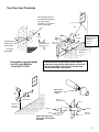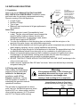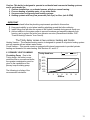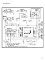
1
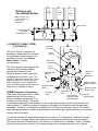
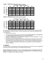
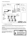
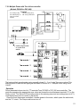
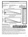
1.0 SPECIFICATIONS................................................................................................. 2
VERSION DATE: 9-1-04
1.1 HIGH ALTITUDE OPERATION ................................................................................. 2
2.0 INSTALLATION REQUIREMENTS .................................................................. 2
3.0 VENTING................................................................................................................ 3
3.1 VENT PIPE MATERIAL .................................................................................... 3
3.2 VENTING CLEARANCES ................................................................................. 3
3.3 VENTING CONFIGURATIONS ........................................................................ 4
3.4 DETERMINING VENT LENGTHS ................................................................... 7
4.0 CONDENSATE DRAIN......................................................................................... 8
5.0 INSTALLING GAS PIPING ................................................................................. 9
5.1 INSTALLATION ...................................................................................................... 9
5.2 TESTING AND SETTINGS ........................................................................................ 9
6.0 HEATING SYSTEM PIPING ............................................................................. 10
IMPORTANT .......................................................................................................... 11
6.1 PRIMARY LOOP PLUMBING......................................................................... 11
6.2 SECONDARY LOOP HEATING SYSTEM..................................................... 14
6.2.1 Multiple Zones using Zone Valves.............................................................. 14
6.2.2 Multiple Zones using Pumps....................................................................... 14
1
14
6.2.3 Multiple Zones with different temperatures................................................ 15
6.3 DOMESTIC COMBI SYSTEM......................................................................... 16
7.0 WIRING................................................................................................................. 18
7.1 SIMPLIFIED WIRING CONNECTIONS ..................................................................... 19
7.2 ADVANCED WIRING SYSTEMS ............................................................................ 20
7.2.1 MULTIPLE 4 WIRE ZONE VALVES ........................................................... 20
7.2.2 MULTIPLE ZONES WITH TACO VALVE CONTROLLER ........................................ 21
7.2.3 Multiple Zones Pump controller................................................................. 22
8.0 SENTRY 2100T CONTROLLER........................................................................ 24
9.0 LIGHTING BOILER ........................................................................................... 27
9.1 INITIAL START-UP ......................................................................................... 27
9.2 RE-LIGHTING UNIT........................................................................................ 27
9.3 TURN OFF BOILER ......................................................................................... 27
10.0 TROUBLE SHOOTING .................................................................................... 28
11.0 SEQUENCE OF OPERATION ......................................................................... 31
13.0 ANNUAL MAINTENANCE AND INSPECTION........................................... 33
13.01 COMBUSTION CHAMBER CLEANING ................................................................ 33
14.0 PARTS LIST ....................................................................................................... 34
15.0 WARRANTY....................................................................................................... 35
SAVE THESE INSTRUCTIONS
Installer must leave, and affix these
Instructions close or adjacent to the boiler
CAUTION: IT IS THE RESPONSIBILITY OF THE
HOMEOWNER TO KEEP THE VENT TERMINAL CLEAR OF
SNOW AND ICE.
Warning
THIS BOILER MUST HAVE WATER FLOWING
THROUGH IT WHENEVER THE BURNER IS
ON. FAILURE TO DO THIS WILL DAMAGE
THE UNIT AND VOID THE WARRANTY.
1.0 SPECIFICATIONS
Description
T150
Input (BTUx1000)
Input Capacity - Max. / Min.
Output (BTUx1000)
Output Capacity - Max. / Min.
Steady State Efficiency
AFUE Efficiency
Venting material
Max. Vent lengths 2”
Max. Vent lengths 3”
Max. Vent lengths 3”
Weight
Dimensions L-W-D
Clearance to Combustibles
T200
Natural =145 / 50
Natural = 200 / 75
Propane= 140 / 50
Propane= 190 / 75
Nat=137 / 47.5
Natural= 188 / 70.5
Propane = 133 / 47.5
Propane = 178.6 / 70.5
95%
94%
91.9%
90.8%
sch. 40
ABS, CPVC, PVC
, AL294C stainless
15 Equivalent Feet
Not permitted
(natural only)
105 Equivalent Feet ((Natural Gas Only))
50 Equivalent Feet ((Propane))
90 lbs.
23.75 – 20.5 – 15
0”
Input (Mbh)
1.1 High Altitude Operation
The Trinity boiler is designed to operate to capacity in installations with 2000 feet of elevation or
less. As elevations higher than 2000 feet have less dense air, the unit is not capable of providing its
specified capacity. The affect of elevation will de-rate the input by approximately 3.6% per 1000 foot
of elevation, (see following Chart).
200
190
180
170
160
150
140
130
120
110
100
0-2000
T150
3000
4000
5000
T200
6000
7000
8000
9000
10000
Elevation (ft)
CAUTION
At elevations greater than 2000 feet, the combustion of the Trinity must be checked with a calibrated
combustion tester to ensure safe and reliable operation. Consult section 5.20 for instructions on
adjusting the input to provide proper operation.
It is the Installers responsibility to check the combustion, and to adjust
the combustion in accordance to section 5.20
2.0 INSTALLATION REQUIREMENTS
2
The installation of your NY Thermal Trinity gas boiler must conform to the requirements of your local
authority, and the National Fuel Gas Code ANSI Z223.1 and or CAN/CGA B149 Installation Codes.
Where required by the Authority, the installation must conform to the standard for “Controls and
Safety Devices for Automatically Fired Boilers ANSI/ASME CSD-1
LIQUEFIED PETROLEUM (LP) PROPANE
Attention: The Trinity boiler is set to operate with Natural Gas, an LP Conversion Kit Part No. 82066-1 is included
with each boiler and must be installed before operating with Propane.
Liquefied petroleum (LP) propane gas is heavier than air; it is imperative that your boiler is not installed in a
pit or similar location that will permit heavier than air gas to collect. Local Codes may require appliances
fueled with LP gas be provided with an approved means, of removing unburned gases from the room. Check
your local codes for this requirement.
2.10 LOCATION
In all cases, the Trinity boiler must be installed indoors, in a dry location, such that the gas
components are protected from dripping or spraying water or rain, during operation and servicing.
The boiler location ambient temperature is maintained to a minimum of 50°F.
Determine the best location of the vent termination, and if possible locate the boiler as close to the
termination point as possible.
Clearances
To ensure proper and safe installation of your boiler, adhere to the following clearances to
combustibles:
Boiler Casing=0"
Floor = Combustible
Flue Pipe: Boxed in or enclosed =2”, In free air=0”
The following are the minimum clearances for servicing, however 24” is recommended:
Front = 24”
Back = 0"
Top = 12"
Sides = 5"
Bottom = 12"
Ensure that the desired boiler location is not subjected to flooding or high moisture levels, for
damage to the boiler will occur, voiding your NY THERMAL warranty.
3.0 VENTING
The NY Thermal Trinity condensing gas boiler is a high efficiency boiler utilizing induced power
venting, which is designed to be vented directly outdoors, using the venting method detailed in this
section. Under no conditions, may this unit vent gases into a masonry chimney, unless it is vacant,
and utilizes the Trinity approved venting material (Solid core ABS Pipe, PVCsch. 40, CPVC pipe,
AL29-4C Stainless steel pipe) as illustrated in the figure on page 5.
3.1 VENT PIPE MATERIAL
Selection of the vent pipe material must be based upon the Local codes and regulations. The
Trinity boiler is certified to operate under all conditions using solid core ABS, PVCsch.40, or
CPVC. Local codes may prohibit the use of plastics, and stainless steel venting must be
used (AL29-4C).
3.2 VENTING CLEARANCES
1. It is highly recommended that the vent terminal be located where it will not be exposed to normal
prevailing winds.
2. The exhaust must be a minimum of 18” above the air inlet, and the air inlet must always be a
minimum of 12” plus snow allowance above any surface that will support snow. (Two feet plus
snow allowance is highly recommended). Consult your weather office, for the maximum typical
snowfall for your region. Example: New Brunswick Canada the maximum typical snowfall is 19”, Thus in figures
of Section 3.3, the inlet must be (12”+19”) = 31” off the ground, the exhaust must be (31”+18”) = 49”.
3
3. The horizontal distance between the inlet and exhaust must be a minimum of 4” center to center.
If the horizontal distance between the inlet and exhaust is more then 12”, increase the vertical
separation by the same amount. Example: If horizontal separation is 24”, a minimum vertical
separation of 30” is required (24”-12”=12”), so increase minimum vertical separation by 12”),
(18”+12”=30”). If horizontal distance is greater then 6’, no additional vertical spacing is required.
Vertical separation is never required to be greater then 36”.
4. Under normal operating conditions this appliance will produce a plume of white gases, and
should be taken into consideration when selecting an adequate location. A 3’ diameter stainless,
plastic, or vinyl shield can be used to flash the exterior of the residence.
The vent terminal shall not terminate:
These are code restrictions for the location
• Directly above a paved sidewalk or a paved
of the Flue gas vent terminal. Compliance
driveway that is located between two
doesn’t insure a satisfactory installation;
buildings, and that serves both buildings;
good common sense must also be applied.
• Less than 7 feet above grade where located
adjacent to a paved driveway or public walkway.
• Within 3' (three feet) horizontally of a window or door that can be opened, or non-mechanical air
supply inlet to any building.
• Within 6’ of a mechanical air supply inlet to any building, or roof eve containing soffit openings.
• Above a meter/regulator assembly within 3' horizontally of the vertical centerline of the regulator.
• Within 6' of any gas service regulator vent outlet.
• Less than 30” plus snow allowance above grade, or any surface that will support snow, ice, or
debris. The exhaust must be a minimum of 18” above the air inlet, and the air inlet must
always be a minimum of 12” plus snow allowance above any surface that will support
snow. (Two feet plus snow allowance is highly recommended). Consult your weather
office, for the maximum typical snowfall for your region.
• Underneath a wooden verandah, porch, or deck.
• Underneath cement verandah, porch, or deck, unless both ends are open and the exhaust pipe
is installed at least 24” under the deck floor.
• So situated that the flue gases are directed towards brickwork, siding, or other construction, in
such a manner that may cause damage from heat or condensate from the flue gases
• Less than 3’ from an inside corner of an L-shaped structure (including walls and fences).
3.3 VENTING CONFIGURATIONS
Selection of acceptable venting materials is as follows.
Vent Piping A -C: See Chart for maximum lengths
• 2” or 3” ABS solid core.
• 2” or 3” PVC schedule 40 pipe.
• 2” or 3” CPVC schedule 40 pipe.
• 3” AL29-4C flex Stainless vent
• 3” AL29-4C Rigid Stainless Vent.
Air Supply Vent B: See Chart for maximum lengths
• 2” or 3” ABS.
• 2” or 3” PVC schedule 40 pipe.
• 3” Galvanized Steel pipe
• 3” Flex Aluminum (MAX 20’)
Warning
Field supplied piping and fittings are required to
complete installation. The combustion air and
vent pipe and fittings must conform to ANSI and
ASTM standard D1785 (schedule 40 PVC),
D2665 (PVC-DWV), and D2661 (ABS-DWV).
Pipe cement and primer must conform to ASTM
standard D2564 (PVC) or D2235 (ABS).
Warning
Never mix 2” and 3” pipe in the same installation.
(All 2” or all 3”)
4
Two Pipe Vent Terminals
The vertical portion of
the exhaust termination
does not require
insulation, if less than 5
feet in total length
36”
18” Min
Coupling and
elbow to be
against wall
Note: horizontal
spacing must be
between 4”
(center to
center).
18” Min.
12” Plus
Snow allowance
Example 12+19=31”
– ½” play is
acceptable
12” plus snow
Allowance
Concentric vent terminal
Use NTI part # 82666 or
York Part# 1CT0303
Clearances and requirements of this manual
supersede, those of the Instructions enclosed in
vent terminal #650.75-N2, which contain more
detailed assembly instructions.
Must insert
plastic bird
screen
36”
min
48”
min.
4” or
greater than 4’
Support
(Field installed)
Minimum 12”
plus snow
allowance
Exhaust
Inlet air
Note: inlet pipe must
always be connected to
the boiler.
Inlet air
Exhaust
Must be 1”
from wall
5
Use of existing Chimney
It is permissible to run vent pipe through an existing chimney as
long as:
1) The chimney is not to be used by any other appliance.
2) Flue gases don’t enter the vacant chimney.
3) Only ABS, PVCsch.40, CPVC, or AL294C pipe is used.
4) Vent lengths are within the maximums specified.
Exhaust
Roof Venting
Inlet Air
24”
18”
Roof weather seal
Flashing (field supplied)
12” Plus
Snow
Note: inlet
pipe must
always be
connected
to the
Inletboiler.
Air
Support
(Field supplied)
Exhaust
Notes
1.) If the horizontal distance between the inlet and exhaust is more then 12”, increase minimum
vertical separation by the same amount. (If horizontal distance is greater then 6’, no
additional vertical spacing is required). Example, horizontal separation equal to 24” requires
a minimum vertical separation of 18”+(24”-12”) = 30”. (Vertical separation is never required
to be greater then 36”)
2.) Elbows on outside of wall must be no greater than ½” away from the wall.
3.) All indoor exhaust piping must be on a slope back to the boiler ¼” per linear foot of vent.
4.) Exhaust and Inlet venting must have screens installed at the termination (See figure on page
6).
5.) Exhaust vent pipe can be secured to the wall for
more rigidity.
6.) In all roof applications the discharge must point
away from the pitch of the roof.
7.) Install adequate flashing where the pipe enters the
roof, to prevent water leakage.
8.) Install and seal a rain cap over existing chimney
openings, in vacant chimney applications.
9.) For installations that exit the wall below grade.
6
Excavate site as shown in figure, to a point below where the pipes are to exit. Ensure that the
wall is fully sealed where the pipes penetrate the wall. The vent piping MUST be secured to
the side of the building above grade, as shown, to provide rigidity. NTI Provides a mounting
bracket PN. 82075 for securing the exhaust pipes. Ensure that the vent clearances are
maintained (Inlet minimum 12” plus snow allowance from grade, exhaust outlet 18” minimum
above inlet).
PN 82075
30” Min. Plus
Snow Allowance
12” Min. Plus
Snow Allowance
10.)
Install the stainless steel screens into both the inlet and
exhaust vent terminal elbows. The screen must be on the outside
of the last elbow. Install the screen into the female opening of the elbow. Then cut a small
piece of pipe to sandwich the screen into the elbow. NOTE be sure that the small piece of
pipe cut, does not extend past the end of the elbow. Two screens for 3” pipe and two
screens for 2” pipe are provided in the package.
3.4 DETERMINING VENT LENGTHS
Warning
Use the following chart to determine the
maximum amount of vent pipe that can be
used. This chart calculates, sweep and 45º
elbows, and 90º elbows at 5 equivalent feet.
Combustion air that contains chloride,
fluoride, bromine, or iodine can cause
corrosion of the heat exchanger,
voiding your warranty.
IMPORTANT: The vent pipe lengths for the air inlet must NEVER EXCEED THE LENGTH OF
THE EXHAUST. The exhaust pipe may exceed the inlet pipe by as much as 20 equivalent feet.
The three 90°elbows of the exterior vent piping (two outlet, and one inlet) do not have to be
included, as they are taken into consideration in the vent calculations.*Note: When fired with
Propane 2” venting cannot be used. The venting must be 3” and can only be used up to 50
feet equivalent.
Model
T150*
T150 & T200
T150 & T200*
Pipe
size
2"
3"
3"
Max. Equiv.
Length
1
15
10
105
100
50
45
2
5
95
40
Number of Elbows or 45
3
4
5
6
7
0
90 85 80 75 70
35 30 25 20 15
8
9
65
10
60
5
7
Vent piping outside the Building is permitted
under the following conditions:
1. The maximum length outside the
building is 20 feet.
2. Only 3” pipe can be used.
3. All normal termination clearances are
maintained.
4. All exterior exhaust vent pipes are
insulated with 3.5”-ID, ½”-thick Closed
Cell Foamed Polyolefin Tubing i.e.,
“Tundra Seal Plus” or equivalent.
5. The pipe is supported every 24”
6. The exhaust and inlet are sloped back
to the boiler ½ ” elevation for every foot.
Supports every 24”
Exhaust
Maximum of 20 feet is
permitted for outside a
building using 3” pipe
ONLY.
Insulation
Inlet
12” plus
allowance
above grade
“Tundra Seal
Plus” 3.5” ID. ½”
thick
4.0 CONDENSATE DRAIN
Warning
This unit produces water as a
Failure to properly connect the condensate
product of combustion. Much of
line will cause combustion gases to enter the
this water condenses on the heat
room, possibly causing serious injury to
exchanger and in the venting
occupants or death.
system. All exhaust piping must
be on a slope back to the boiler
¼” per linear foot of vent. Steps must be taken to ensure that condensate does not collect in the
venting system. Condensate must be drained from the boiler into a household drain. (Note check
with your municipality, or local gas company to determine if
disposal of combustion condensate is permitted)
Clamp Y
to pipe
The following are important notes that must be taken into
Minimum 24”
Water
consideration when constructing the condensate system:
from Y to loop
level
• Construct a small loop using 1/2” silicone, rubber,
Min. 12”
reinforced nylon, or PEX tubing to create a trap, so
Don’t seal
Diameter
that combustion products do not escape into the
opening. Allows
boiler to drain
room via the drain. Do not use nylon, as it will
if 1½” pipe
collapse, blocking drainage, and could damage
becomes blocked.
the boiler.
• This trap must be primed with water, by adding a
1½” pipe
cup of water into this loop, prior to connecting it to
the unit.
• DO NOT run condensate line outside. A frozen or blocked drain will cause the condensate to
fill the combustion chamber. This will result in a no heat condition, as the unit will shut down,
and damage to the flame sensor, and components can occur.
• NEVER use copper, steel, or galvanized piping in the construction of the condensate system.
• When a condensate pump is used or required, select a pump that is designed for residential
furnaces.
8
5.0 INSTALLING GAS PIPING
It is highly
Gas cock
5.1 Installation
recommended to use
shut Off
flexible gas pipe, the
Refer to the current National Fuel Gas Code ANSI
Valve to be
gas valve and blower
"T" type
Z223.1/NFPA 54 or CAN/CGA B149.1 installation codes,
cannot support the
handle
weight of piping. If
and local codes for gas piping requirements and sizing.
piping is used, ensure
Pipe size running to the unit depends on:
that the valve supports
NO WEIGHT
• Length of pipe.
• Number of fittings.
• Type of gas.
• Maximum input requirement of all gas appliances in
Gas valve
the residence.
Insure that:
Air Inlet
• Flexible gas pipe is used (if acceptable by local
codes). The gas valve and blower cannot support the
weight of piping, leading to blower vibration and
damaged components. If rigid piping is used, ensure
that the valve supports NO WEIGHT
• You plan the installation so that the piping does not interfere with the vent pipe, or the
removal of the valve, burner, and serviceable components.
• The Boiler shall be installed such that the gas ignition system components are protected from
water (dripping, spraying, rain etc.) during installation and servicing.
• The gas piping is large enough for all the appliances in the home. No appreciable drop in line
or manifold pressure should occur when any unit (or combination of units) lights or runs.
• Always use a pipe-threading compound that is resistant to propane (LP) gas solvent action.
Use sparingly to all male threads, starting at two threads from the end. Over doping or
applying dope to the female end, can result in a blocked gas line.
• DO NOT TIGHTEN FITTINGS WITHOUT SUPPORTING THE GAS VALVE as damage to the
valve or motor can occur.
• Install a manual “equipment Shut-Off Valve” as shown. Valve must be listed by a nationally
recognized testing lab.
5.2 Testing and settings
When running, the line pressure
supplying the unit must be 4-9
inches w.c. for Natural gas
installations and 9-12” for
Propane installations. Ensure
that the regulator is capable of
maintaining this pressure under all
operational conditions.
The gas valve is equipped with two bleed
ports; one is for the Manifold pressure, which
must be 0.00” w.c. when running, and the
other is the line pressure. (4-9” for natural
and 9-12” for Propane while running)
Warning
If line pressure exceeds ½ PSI (14 inches w.c.)
completely disconnect line to gas valve. This
excessive pressure can damage valve,
causing a leak resulting in fire or explosion.
Normal Range of Gases in Flue Gases
(At maximum fan speed of 205 on Sentry display)
Carbon Dioxide
CO2 %
Carbon Monoxide
CO ppm
NOX ppm
Natural
Gas
8-9.5
Propane
25-175
25-175
10-50
10-50
9-10.5
9
Manifold
Line Pressure
The input Screw “MUST NEVER
BE ADJUSTED” unless you
have a calibrated combustion
analyzer to verify the
combustion properties are within
normal operating ranges.
The Trinity boiler employs a
pneumatic modulation system.
This modulation system
increases or decreases the
velocity of the blower, to meet
the demand for heating. The gas
valve, senses this change, in
blower pressure, and introduces
Input Screw
the required amount of gas, to ensure correct combustion.
Caution
The Trinity is tested
with natural gas having
a heating value of 1020
BTU per cubic foot. For
areas with lower
heating values, a
combustion test is
required to obtain
optimum operation.
Input Screw
Decrease gas
Turn Clockwise
Increase gas
Turn counterclockwise
.
IF FOR ANY REASON THE INPUT SCREW IS
ADJUSTED, A “COMBUSTION ANALYZER” MUST BE
USED TO ENSURE SAFE AND PROPER OPERATION.
6.0 HEATING SYSTEM PIPING
Warning
This boiler must have adequate water flowing through it
whenever the burner is on. Failure to do this will damage
the unit and void the warranty.
Warning for all Systems
All systems must be flushed to remove sediment, flux,
filings, etc. Failure to do so will seriously damage the
boiler, voiding warranty. (Recommend using Fernox
cleaning products “Superfloc” for new installations and
CHR “Central Heating Restorer” for retrofits)
Warning for all Systems
The boiler fittings can’t support any weight. Support all
of the plumbing system externally.
Do not apply torque to the boiler fittings. Hold the fitting
when installing, otherwise damage to the unit will occur.
10
Caution: This boiler is designed to operate in residential and commercial heating systems,
and is not intended for:
1. Outdoor installations, or unheated spaces, which can cause freezing.
2. Process heating of potable water, or any other fluids.
3. Un-pressurized, and gravity feed heating systems.
4. Heating systems with very low pressures (min 5 psi) or flow. (min 6 GPM)
IMPORTANT
1. Understand and follow the plumbing requirements provided in this section.
2. Keep serviceability in mind when installing plumbing around the boiler cabinetry.
3. Install fittings that will allow the system to be flushed if needed during annual check-ups.
4. Add an inhibitor to the system water to prevent limestone and magnetite deposits from
forming, and to protect the boiler from galvanic corrosion (Recommend inhibitor CHP,
“Central Heating Protector” from Fernox).
The Trinity boiler comes in two versions, heating and Combi.
Heating Version – The standard heating version is designed to operate in a hydronic heating system
and can operate with an indirect water heater.
Combi Version – This special version is equipped with internal components to provide hydronic
heating and domestic hot water heating. See Sections 6.1 and 6.3.
The following is a listing of the
recommended circulators.
Trinity Head loss
T150
T200
50.0
Feet of Head
6.1 PRIMARY LOOP PLUMBING
Circulating Pump Due to the
Trinity design, the boiler is more
restrictive than a conventional boiler,
thus greater consideration must be
given to the capabilities of the
primary loop-circulating pump.
40.0
30.0
20.0
10.0
0.0
2
4
6
8
10
GPM us
12
14
11
Restriction
Model Head Loss
Minimum
Flow (us
Max. Temp.
Rise
Minimum Primary Pump Size
B&G
GPM)
T150
T200
7’ at 6 GPM
10’ at 8 GPM
6
8
45°F
45°F
Grundfos
NRF-33
PL-36
UP 26-64
UP 26-99
Taco
0010
0011
Relief Valve (30PSI) Is provided with the system, and it is to be mounted as shown in the
diagram. Ensure that the discharge of the pressure relief is piped to a location were steam or water
won’t cause personal injury or appliance and property damage.
Boiler Venting Hot water boilers are designed to operate with airless water in the system. The
Trinity boiler is provided with a 1/8” Air vent located on the top of the unit. This Air vent is intended to
vent the boiler on initial startup. This device will NOT continuously vent air collecting in the primary
loop, and it is not intended to be the primary venting device. The Air Scoop as shown in the diagram
is the primary venting location. It is recommended that an additional Air Scoop be used in the
secondary plumbing. If air continues to be a problem an air scrubber must be used (recommend
Spriovent # VJR 100TM or VJR 125TM).
Low Water Cutoff A certified low water cutoff is not provided in the package, however it is to be
field installed in any application where the boiler is located above ALL the radiation.
Plumbing
• Ensure that the water line of the “Low
Water Cutoff” is at least 6” above the
top of the boiler.
• It is recommended that the LWCO be
situated so that it can be tested
without removing water from the
boiler. Tri-cocks and a gauge glass
are highly recommended.
• It is recommended that no gate valves
be installed between the LWCO and
the boiler.
• Use an air vent if installed as per our
diagram to be used as a vacuum
breaker and to eliminate air upon
filling.
Low Water cut off
Water Line
Air Vents
Break red wire
in the Trinity
control box and
switch with
relay. Circuit is
1 amp, 24V to
igniter and gas
valve.
No shut off
valve between
the boiler and
LWCO.
Electrical
• Break the red wire looped in the
Trinity control box, and wire the
normally open contacts of the LWCO
in series with the two red wires.
Circuit is 24 volts, 1 amp.
The Trinity boiler is to be used only in a Primary / Secondary pumping system. This is to
avoid cycling problems in systems that have poor flow, or heating zones with very small
capacities. The primary loop system must be used in all cases, regardless of the
configuration of the secondary system design.
12
E
Primary Loop
For Heating Model
With option Indirect Water
heater
There must be
no shutoff
valve between
the boiler and
the relief
valve.
Quantity and location of
shutoff valves, and drains, are
at the discretion of the
installed.
O
Water
Supply
Heating Model
Important
A- Back flow preventor
B- Fill valve (set at 12 psi)
C- Diaphragm expansion tank
D- Cast Iron Air scoop, for excessive air
conditions use Spirovent.
E- Automatic air vent
F- Relief valve (set at 30 psi)
G- Pressure gauge
H- Heating pump (see size
recommendation on page 10) Wired
to terminals C1 - L2
I- Optional Indirect pump (see
recommendation on page 10) Wired
to terminals Ap - L2
J- Optional Indirect Water heater
K- Check Valve
L- Check or flow valve, (use a flow
valve if zone valves are not used in
distribution system, to prevent
gravity feeding).
M- Boiler Drain
N- Boiler inlet connection (warm)
O- Boiler outlet connection (hot)
N
F
D
Legend
1-1/4” Pipe
Recommended
G
E
B
A
C
I
J
K
L
H
Insert secondary
Loop here.
See page12 & 13
E
Primary Loop
For Combi
Model Only
Combi Model
Legend
ABCDEFGHIJKL-
Back flow preventor
Fill valve (set at 12 psi)
Diaphragm expansion tank
Cast Iron Air scoop, for
excessive air conditions use
Spirovent.
Automatic air vent
Relief valve (set at 30 psi)
Pressure gauge
Heating pump (see size
recommendation on page 10)
Wired to terminals C1 - L2
Boiler Drain
Boiler outlet connection (hot)
Boiler inlet connection (warm)
External Combi Manifold
#82470
J
Water
Supply
G
Primary Boiler loop
Primary Boiler loop
M
D
H
F L
1-1/4” Pipe
Recommended
E
K
A
B
C
I
Insert secondary
Loop here.
See page12 & 13
13
Flow: The Trinity boiler must have water flow going through the boiler whenever the burner is on.
CAUTION: DAMAGE WILL OCCUR IF THE BOILER IS FIRED WITH NO WATER IN IT, OR REPETITIVE
NO FLOW OPERATIONS, WHICH WILL VOID THE WARRANTY.
6.2 SECONDARY LOOP HEATING SYSTEM
The following are typical piping systems. It is the responsibility of the installing contractor to
determine which system best meets the need of the installation. Contractor modifications to these
instructions may be required, based upon existing piping and system design.
6.2.1 Multiple Zones using Zone Valves
Max. 12” apart
Primary
Loop
Normally closed 4
wire Zone Valves
With End Switches
See figure
Zone
1
Zone
2
Zone
3
7.2.1 “Multiple 4 wire Zone Valves”
for wiring
7.2.2 “Multiple Zones with Taco Valve
controller
6.2.2 Multiple Zones using Pumps
Max. 12” apart
1
Primary
Loop
Pumps sized to each
zones flow and head
requirements
Zone 1
Zone 2
See figure
7.2.3 “Multiple Zones using pumps
and pump controller”
Installer may require throttling and
check valves to correctly regulate the
system
Zone 3
14
6.2.3 Multiple Zones with different temperatures
Using pumps and tempering valves
Max. 12” apart
Primary
Loop
See figure
Tempering valve
7.2.3 “Multiple Zones using pumps,
and pump controller”
Zone 1
Low Temp.
By setting the tempering valves to
different settings, multiple
temperatures can be obtained.
Zone 2
Med. Temp.
Installer may require throttling and
check valves to correctly regulate the
system.
Zone 3
High Temp.
Other configurations may work, but
under no circumstances can a mixing
valve be placed in the primary loop as
overheating of the boiler could occur.
Pumps sized to each
zones flow and head
requirements
Using Injection pumps
Boiler sensor #1
(Hi Temp.)
Max. 12” apart
Boiler sensor #2
(Lo Temp.)
Max. 12” apart
See figure
Primary loop
Injection
Pump
7.2.4 “Multiple temperature Zones
using injection pump”
Injection
Pump
Installer may require throttling and
check valves to correctly regulate
the system
Max. 12”
apart
Mix sensor #1
(Hi Temp.)
Loop 1
High
Temp.
Max. 12”
apart
Mix sensor #2
Lo Temp.)
Loop 2
Low
Temp.
Loop Pumps sized to each loops flow and head requirements
15
Primary Loop
For multiple boilers
Boiler
1
Boiler
2
Boiler
3
Note: See page 11 for
location of expansion
tank and other
components
Check Valves
Insert secondary
Loop here.
See page12 & 13
6.3 DOMESTIC COMBI SYSTEM
((( OPTIONAL)))
The Trinity Combi is designed for
installations where space is restricted.
For applications where space is not
restricted, the use of an “Indirect
Water Heater” is highly
recommended.
The Trinity Combi incorporates all the
features of the Standard Heating
version, plus External Combi
Manifold, diverting valve, plate heat
exchanger & flow switch. Note: The
installer is required to install the ¾” pump
flange (included in Combi kit) onto the
boiler return pipe prior to installing the
boiler; the bolts must be inserted into the
flange prior to installing the flange.
COMBI Sequence of operation
Pump
1
Pump
2
Pump
3
Electronic
Thermister
3 way
diverting
Plate heat
exchanger
Flow
Switch
Heating &
Combi
Circulator
Cold Domestic
Water in
Check Valve
External Combi
Manifold #82470
Mixed Domestic
Water
Throttling
Valve
Tempering
Valve
Two Drains for
cleaning of plate
heat exchanger
Heating System
Return (cool)
When water flow greater than .5 GPM
Heating
passes through the flow switch, it
System Supply
closes a contact to terminals A-C on
the Sentry 2100 controller. The boiler
is immediately energized (if not already on), the 3-way diverting valve moves to the domestic hot
water position “A”, and the circulator is energized. Hot water is circulated through the plate heat
exchanger. The flame is modulated to maintain the “LO” setting on the Sentry control. The Sentry
uses the boiler thermister to read the temperature of the boiler water. Space heating is not provided
during a call for domestic.
To improve domestic hot water performance Sentry versions T1.5 and newer, installed on Combi
boilers, go into a “Storage Mode” when demands for both space and domestic heat are finished.
The control will enter “Storage Mode” if the burner is on at the end of a demand. Once in “Storage
Mode” the burner goes to low fire, the 3-way diverting valve is energized (position “A”), and the
16
circulator is powered until a boiler temperature of 185°F is reached, at which point the control
reverts to “Standby Mode”. The “Storage Mode” will be interrupted by either a call for space or
domestic heat.
DHW Check Valve A check valve on the cold water supply to the domestic hot water (DHW)
system is recommended. In some applications surges in water pressure due to a “Water Hammer”
device can cause the flow switch in the boiler to active, giving a false call for domestic hot water. A
check valve installed as per the diagram will eliminate this occurrence.
Anti-Scald Valve A Sparcomix AM101-US-1 is
provided with your package. This valve regulates the
water temperature leaving the plate heat exchanger,
and must be used in every instance. The dial can
be set to the desired temperature required. Consult
the Honeywell manual SD/IS150 for detailed
instructions and settings. (Note: the valve must be
set to a supply temperature of not more then
120˚F. It is the responsibility of the installer to
set the valve and remove the dial.)
Warning
If the Anti-Scald Valve is not
installed to the Honeywell
Sheet SD/IS150, and this
manual, operation may supply
SCALDING hot water to the
Hard Water Hard water conditions will cause the components of this appliance to form scale and
impede the normal operation of the unit. Water with hardness higher than 50 ppm Calcium
carbonate must incorporate a “Water Softener” prior to entering the appliance. Plugging of domestic
system by scaling or accumulation of dirt is not the responsibility of NY Thermal Inc., and suitable
steps shall be taken to avoid it.
Cleaning
Secespol brazed plate heat exchangers operate with high turbulence flow, even at low
flow rates. This high turbulence keeps small particles in suspension minimizing fouling and scaling.
However, in some applications the fouling tendency can be very high, e.g. when using extremely
hard water at high temperatures. In such cases it is always possible to clean the exchanger by
circulating a cleaning liquid. Use a tank with weak acid, 5% phosphoric acid or, if the exchanger is
frequently cleaned, 5% oxalic acid. Pump the cleaning liquid through the exchanger. For optimum
cleaning, the cleaning solution flow rate should be a minimum of 1.5 times the normal flow rate,
preferably in a back-flush mode. After use, do not forget to rinse the heat exchanger carefully with
clean water. A solution of 1-2% sodium hydroxide (NaOH) or sodium bicarbonate (NaHCO3) before
the last rinse ensures that all acid is neutralized. Clean at regular intervals.
Combi Limitations As the Trinity produces domestic hot water instantaneously, there are inherent
limitations that this system has.
1) NO STORAGE - As there is no water storage, the boiler can only provide water at the
temperature specified at the corresponding flow rates. Flow through the fixtures must be regulated
so flows don’t exceed the ability of the boiler to heat the water. MORE FLOW = LESS
TEMPERATURE
2) DOESN’T MAINTAIN TEMPERATURE – When there is no call for domestic the unit is off. From a
dead stop the unit will detect flow and start providing heat in 15 seconds, and be up to capacity by
25 seconds. Once running, the unit can provide an endless amount of hot water. If the flow is
momentarily turned off for whatever reason, the unit will turn off. Once off, the unit must relight, and
not provide heat for 15-25 seconds. This will cause cold unheated water to pass through the unit,
and advance through the domestic plumbing between the previously heated (hot) water, and the
new (hot) water. This can be mistaken for an inability to adequately heat the water.
Procedure for Setting up Domestic Hot Water If the combi boiler is being installed in an
application that uses municipal water, often the pressure is high enough to generate flow rates at
the faucets that will exceed the boilers capacity to heat it. See the following tables to determine
what flow can be expected at various inlet and outlet water temperatures.
17
Outlet Water (F)
Table 1: T150C Flow rates (flow rates in usgpm)
110
115
120
125
130
135
140
40
3.9
3.6
3.4
3.2
3.0
2.8
2.7
Inlet Water Temperature (deg. F)
45
50
55
60
65
4.2
4.5
4.9
5.4
6.0
3.9
4.2
4.5
4.9
5.4
3.6
3.9
4.2
4.5
4.9
3.4
3.6
3.9
4.2
4.5
3.2
3.4
3.6
3.9
4.2
3.0
3.2
3.4
3.6
3.9
2.8
3.0
3.2
3.4
3.6
70
6.7
6.0
5.4
4.9
4.5
4.2
3.9
Outlet Water (F)
Table 2: T200C Flow rates (flow rates in usgpm)
110
115
120
125
130
135
140
40
5.1
4.8
4.5
4.2
4.0
3.8
3.6
Inlet Water Temperature (deg. F)
45
50
55
60
65
5.5
6.0
6.5
7.2
8.0
5.1
5.5
6.0
6.5
7.2
4.8
5.1
5.5
6.0
6.5
4.5
4.8
5.1
5.5
6.0
4.2
4.5
4.8
5.1
5.5
4.0
4.2
4.5
4.8
5.1
3.8
4.0
4.2
4.5
4.8
70
9.0
8.0
7.2
6.5
6.0
5.5
5.1
To avoid having too much flow at your faucets use the shut off valve after the mixing valve to limit
the overall flow of domestic hot water. Follow these instructions to achieve the best results with
your combi boiler:
1. Open shut off valve fully.
2. Turn the dial on the mixing valve to the desired setting (being careful not to exceed 120˚F
or a dial setting greater then 2) and adjust LO setting accordingly.
3. Create the maximum amount of DHW flow that is likely to occur on a regular basis. (Usually
tub faucet, or choose two other faucets)
4. Allow the boiler to reach steady state, and then throttle the shut-off valve until the hot water
exiting the plate heat exchanger is warmer than the mixed water exiting the mixing valve.
Ensure the boiler is firing at the maximum rate, if not increase the LO setting and repeat this
step. (It is beneficial to keep the LO setting as low as possible to limit short cycling and
maintain efficiency)
7.0 WIRING
All wiring must be in accordance with the Canadian Electrical code, CSA C22.2, and any applicable
local codes. Ensure that the wiring is in accordance with this manual.
Contact capacity of outputs C1 or Ap is 3 running Amps with a maximum inrush of 6
Amps. If the capacity of the pumps is in excess of these maximums, you must either use a pump
controller, or isolation relay to energize the pumps.
18
7.1 Simplified Wiring Connections
Heat and Indirect Wiring
120 Volt Wiring
Primary Heating Circ
Low Voltage (DC)
Secondary Heating Circ
10K Outdoor probe
Blue
Green
Electrical Box
Red
Purple
Black
White
DHW Circ
Caution
120/1/60
15 Amp Fused
Power Supply
For LWCO
cut Red
Circuit
Indirect Aquastat
Thermostat end
switch or heat
starter
Contacts that energizes
these inputs MUST BE
DRY CONTACTS ONLY
Combi Wiring
120 Volt Wiring
Primary Heating Circ
Low Voltage (DC)
Secondary Heating Circ
10K Outdoor probe
Blue
Green
Electrical Box
White
Black
Flow Switch
Red
For LWCO
cut Red
Circuit
Caution
120/1/60
15 Amp Fused
Power Supply
Thermostat end
switch or heat
starter
Contacts that energizes
these inputs MUST BE
DRY CONTACTS ONLY
The boiler must be electrically grounded in accordance with the National Electrical Code
ANSI/NFPA 70, or local codes, and/or the Canadian Electrical Code CSA C22.1.
Warning!!! A bad installation could ruin the Sentry
Board and void your warranty.
• Before providing 120 Volts to the boiler, do a continuity check between all wires and ground to
make sure that there are no electrical leaks that could damage the board.
• Do not use magnetic tip screwdriver near the Sentry board.
• Verify that the wires connected to the Sentry TC and AC terminals are not grounded, or
have any voltage applied to them, or voltage to ground (dry contact closure only).
• Ensure that the probe wire is not damaged.
• Caution: Label all wires prior to disconnecting them when servicing controls. Wiring errors can
cause improper and dangerous operation
19
7.2 Advanced Wiring Systems
Legend
P1- Primary Pump
P2- Indirect pump, or
3-way on Combi
Version
P3-Secondary pump
CB- Trinity Control box
4 wire zone
valves
Power open,
spring return
Indirect
thermostat, or
combi flow
switch
7.2.1 Multiple 4 wire Zone Valves
The basic multiple zoned system uses normally closed four (4) wire zone valves. This wiring system
is used with the piping as described in Section 6.2.1 “Multiple Zones using Zone Valves”.
Operation
Room thermostat closes circuit to zone valve motor, thus opening the valve. When the valve is
opened, the end switch closes the circuit between terminals T-C on the Sentry control. The Sentry
2100 provides power to the primary pump and secondary pump via (C1), once these pumps are on,
it turns on the burner.
Once the room thermostat is satisfied, it breaks
power to the motor, which opens the end
switch, and the T-C circuit. The Pumps and
burner turn off.
Warning
Maximum current of blue wire
(C1) is 6 amps, with all pumps
running. Current in excess of 6
Amps, will damage the board,
and void the warranty.
20
7.2.2 Multiple Zones with Taco Valve controller
(Models ZVC403 to ZVC 406)
Legend
P1- Primary Pump
P2- Indirect pump, or
3-way on Combi
Version
P3-Secondary pump
CB- Trinity Control box
Indirect thermostat,
or combi flow
switch
The basic multiple zoned system using normally closed 2 – 3- or 4 wire Taco zone valves. This
wiring system is used with the piping as described in Section 6.2.1 “Multiple Zones using Zone
Valves”.
Operation
Room thermostat closes circuit to TT terminals Taco ZVC403 to ZVC 406 zone controller. The
controller energizes the appropriate zone valve and closes the circuit between terminals T-C on the
Sentry control. The Sentry 2100 provides power to the primary pump and secondary pump via (C1),
once these pumps are on it turns on the burner.
Once the room thermostat is satisfied, it breaks power to the motor, which opens the end switch,
and the T-C circuit. The Pumps and burner turn off.
21
7.2.3 Multiple Zones Pump controller
(Models Taco SR504, Argo ARM 861 Series)
Legend
P1- Primary Pump
P2- Indirect pump, or
3-way on Combi
Version
P3-Secondary pump
CB- Trinity Control box
Indirect
thermostat,
or combi flow
switch
The basic multiple zoned system using circulating pumps. This wiring system is used with the piping
as described in 6.2.2 Multiple Zones using Pumps and 6.2.3 Multiple Zones with different
temperatures.
Operation
Room thermostat closes circuit to TT terminals of the pump controller. The controller energizes the
appropriate circulating pump and closes the circuit between terminals T-C on the Sentry control. The
Sentry 2100, provides power to the primary pump (C1), once the pump is on, it turns on the burner.
Once the room thermostat is satisfied, it breaks power to the TT terminal of the pump controller,
which opens the X –X contacts, which opens the T-C circuit. The Pumps and burner turn off.
22
7.2.4 Multiple Temperature Zones with Injection Pumps
Loop #1, Hi Temp.
(Models Taco SR504, Argo ARM 861 Series And Tekmar 356 controller )
Indirect thermostat, or
combi flow switch
Loop 2 (Lo Temp.)
Thermostat, or
manifold end switch
Legend
P1- Primary Pump
P2- Indirect pump or 3-way Valve in Combi
CB- Trinity Control box
IP- Injection Pump
ZP- Zone Pump
BS.- Strap on boiler sensor
MS.- Strap on mixing sensor
ODS.- Outdoor sensor
Loop #2, Lo Temp.
Loop 1 (Hi Temp.)
Thermostat, or
manifold end switch
This wiring system is used with the piping as described in 6.2.3 Multiple Zones with different
temperatures ((Using Injection pumps))
Operation
Room thermostat or the end switch of a zoned manifold closes the circuit to TT terminals of the
pump controller. The pump controller then:
1. Sends 120 volts to the zone pumps (which circulates mixed water throughout the loop).
2. Sends 120 volts to the injection pump, through the 356 Tekmar controller.
3. Closes the circuit between terminals T-C on the Sentry control. The Sentry 2100 provides
power to the primary pump via (C1), once the pump is on, it turns on the burner.
The 356 controller reduces or increases the speed of the injection pump, depending on the
temperature at the “Mix sensor”.
23
Once the room thermostat is satisfied, it breaks power to the TT terminal of the pump controller,
which opens the X –X contacts, which opens the T-C circuit. The Pumps and burner turn off.
In an injection system, it is important to understand the effect of flow and temperature set points. It is
recommended that the Sentry controllers set point is at least 20°F higher than the desired Mix
temperature of the Hottest Loop.
Consult the Tekmar installation manual for detail installation and operation of this control.
8.0 SENTRY 2100T CONTROLLER
The Sentry controller is the central controller for the Trinity boiler. The Sentry handles all the
combustion logic, together with the energy management functions. The Sentry 2100T operates in two
different modes, reset or conventional. The mode is automatically determined by the presence of the
outdoor sensor. When the Sentry 2100 detects the presence of the outdoor sensor the controller will
operate in Reset Mode. If the outdoor sensor is not installed, the controller will operate in
Conventional Mode. If outdoor sensor is connected after start-up must power boiler off and on.
Sentry Display
The following describes the meaning of the lights on the Sentry controller.
LED Display indicates the value of
the information being displayed.
Green Lights
Burner/Bruleur = Indicates that the ignition
system is activated
Circ. = Indicates that the heating pump is
energized
Circ. Aux.= Indicates a call for DHW, and
Indirect pump or 3-way valve is activated.
Thermostat Demand= Indicates that terminals
T-C are closed, iniating a call for heat.
Water/Eau = When
illuminated, indicates
that the display is
showing boiler water
temperature.
Air = If the air sensor is
being used. When
illuminated, indicates
that the display is
showing outdoor air
temperature.
Gas Input Value=
When illuminated,
indicates that the
display is showing the
current input level (45205). See Chart to
determine input.
Indirect Water Heaters
BTU (000's)
Display Data - Input conversion chart
200
175
150
125
100
75
50
205
T150
185
T200
165
145
125
105
85
DHW Temp. =
When illuminated,
indicates that
there is a call for
domestic hot
water.
65
45
The Sentry 2100 comes with
an input and output for a
120-volt indirect pump. When
the A-C terminals are closed
(dry contact) the boiler will go
immediately to indirect
domestic mode, whereby the
indirect pump is activated,
and the boiler will modulate
to the LO setpoint.
LED Display
24
Setting Sentry 2100T Operation
The Trinity boiler employs a pneumatic modulation system. This modulation system increases or decreases
the velocity of the blower, to meet the demand for heating. The gas valve, senses this change, in blower
pressure, and introduces the required amount of gas, to ensure correct combustion. The term “Set Point” is
used to indicate the desired temperature that the Trinity will try and maintain, by increasing or decreasing the
input.
Condition
Set Point
Burner On
Burner Off
Heat Circ.
Aux. Circ.
Condition
Set Point
Burner On
Burner Off
Heat Circ. (C1)
Aux. Circ. (Ap)
T-C & A-C Open
T-C Closed & A-C open
T-C Closed & A-C Close
T-C Open & A-C Closed
Standby Note 3
Off
Off
Heating Only
HI
HI – DIF
HI + 10
On
Off
Domestic Only
L0
LO-10
200°F
Off Note 1
On Note 2
Domestic Only
L0
LO-10
200°F
Off Note 1
On Note 2
T-C & A-C Open
T-C Closed & A-C open
T-C Closed & A-C Close
T-C Open & A-C Closed
Standby Note 3
Off
Off
Heating Only
HI Calc.
HI Calc – DIF
HI Calc + 10
On
Off
Domestic Only
L0
LO-10
200°F
Off Note 1
On Note 2
Domestic Only
L0
LO-10
200°F
Off Note 1
On Note 2
Note:
1- For Combi units the Heating Circ. (C1) is powered for both heating and domestic hot water.
2- For Combi units the Aux Circ. (Ap) powers the 3-way diverter valve. (Located in the boiler)
3- For Combi units (version 1.5 or higher) theo boiler will run in domestic mode immediately following a call for heat or
domestic, until a boiler temperature of 185 F in reached.
Setting Sentry 2100 control
Programming is accomplished by a series of three push buttons located on the bottom side of the
control. (Function, ↑ and ↓). To enter the programming mode, press the function key once. To
scroll through the various menu options depress ↑ until the menu is displayed. To alter the value
press Function once, and the current value will be displayed, then use ↑ for up, and ↓ for down,
until the desired value is obtained. To enter the selected value press Function, which will return to
the menu. When all desired values are selected, scroll to the RUN menu, and press Function, which
exits the Programming Mode and initiates normal operation. A safety feature has been added to
ensure that if the control is left in the Program Mode, the unit will turn off if left in program mode
longer than 30 seconds without receiving an input. Press Function once to continue programming
or to start boiler operation.
MENU
Differential
1-40°F
Boiler Setpoint for
DHW (80-200°F)
Stores Values
& initiates
RUN
LO
Sets Starting Gas
Sets Lowest Gas Input
Input Value (60-100)
Value (45-100)
Sets Outdoor Reset
Sets Highest Gas Input
Indirect Water Heater
Curve Slope (70°F-HI)
Value (100-205)
Error Code (On/Off)
Boiler Setpoint for
Heating (80-200°F)
HI
DIF
RES
SFS
HFS
LFS
ER5
To start the control operation, you must return to RUN on the menu, and press Function. Normal operation will
begin.
25
Determining Reset Temperature HICalc
Once the control identifies the presence of a good outside sensor, the control will automatically reduce the HI setting,
based upon the outdoor temperature. The calculated HI setpoint (HICalc ) is calculated as follows: Example: Hi=200,
RES=70 , Air Temperature=32
RESET RATIO
= (High Setting - RES)/RES
= (200 - 70) /70
= 1.85
RESET TEMPERATURE HICalc
=[(RES-Outdoor Air) x Reset Ratio] + RES
=[(70-32) x 1.85] + 70
=[70.6] + 70
=140.6°F
Note:
THE DESIGN TEMPERATURE IS
0°F OUTSIDE AIR, SO AT 0°F
OR LESS, THE HI SETTING IS
USED, AND NOT SURPASSED.
Hi Setting & Water
Temp. (F)
200
180
160
140
120
100
80
60
-10
0
10
20
30
40
50
60
70
80
90
Outdoor Temperature (deg.F)
Hi Setting & Water
Temp. (F)
Reset Curve for Res=70
200
180
160
140
120
100
80
60
-10
0
10
20
30
40
50
60
Outdoor Temperature (deg.F)
70
80
90
These graphs are examples of reset temperatures based
upon different set points and outdoor air temperatures. The
vertical axis is the water temperature that the boiler will
maintain, and is also the Hi setting of the Sentry 2100
control. The Horizontal axis is the outdoor air temperature.
Reset Curve for Res=85
Recommended settings:
When determining the setting, ask
System
Hi
Dif
RES
yourself, what is the hottest boiler
Finned Tube Baseboard
190°F
20°F
85°F
temperature required on the coldest
Cast Iron Radiators
150°F
20°F
85°F
day=HI SETTING, and what is the
temperature I want to generate for my indirect =LO SETTING. Keep in mind, that the lower the
water temperature the boiler operates at, the higher the system efficiency will be.
The LO setting is only used during a call for DHW (when A-C terminals are closed). Set the LO to
the temperature you require for the Indirect Water Heater (recommend 140°F) or at least 30°F
higher than the indirect Aquastat (recommend 110°F). Refer to “Procedure for Setting up DHW” in
Section 6.30 to achieve proper LO setting for Combi boiler (recommend 160 for T150C and 170
for T200C). If the A-C terminals are not used, the LO setting is not used.
Outdoor Sensor – Shall be installed to take advantage of the energy saving features of the Sentry
Controller. Install the sensor preferably on the north, or coldest side of the building, not within 10
feet of the discharge of the gas vent outlet, or other sources of heat.
26
9.0 LIGHTING BOILER
9.1 INITIAL START-UP
• Ensure that the boiler is wired in accordance with this manual.
• Ensure that the gas shut-off valve is turned on, and that the gas system has been fully
tested for leaks.
• Ensure that the system is completely filled with water, and that ALL the air is purged out.
1. Turn on power to the Trinity Boiler. The boiler should run through a purge, and combustion
should occur. (The control system has a built in ignition retry, allowing the system to retry at least
four times, before locking-out.)
2. Verify that the gas line pressure is 4-9”wc. for natural gas, and 9-12” wc. for propane.
3. Using an appropriate Oxygen or Carbon Dioxide analyzer, take a sample of the flue gas. The
sample must fall within the acceptable ranges for carbon Dioxide, which is 8% - 9.5% for natural
gas, and 9.0%-10.5% for propane. If the reading does not fall within this range, contact NY
Thermal, for assistance.
4. Perform at least three lights in succession to ensure proper operation.
5. After the three successive lights, unplug the flame probe, and allow the unit to cycle again.
Ensure that it tries to light, and locks out on safety reset. Once you have successfully activated
the flame safety system, replace the wire on the flame sensor, and reconfirm proper lighting.
For Your Safety, Read before operating
A. This appliance does not have a pilot. It is equipped
Warning
with an ignition device that automatically lights the
If you do not follow these
burner. Do not try to light the burner by hand.
instructions exactly, a fire
B. BEFORE OPERATING, check all around the
or explosion may result
appliance area for gas. Be sure to check next to
causing property damage,
the floor, as some gases are heavier than air, and
and loss of life.
will settle on the floor.
C. Use only your hand to turn gas knobs, never use a tool. Forcing the valve, or attempting to
repair it can cause fire or explosion.
D. Do not use the appliance if any part is under water.
9.2 RE-LIGHTING UNIT
1. Stop and read these instructions very carefully.
2. Set the thermostat to the lowest setting, and then turn off all power to the boiler.
3. This appliance does not have a pilot. It is equipped with an ignition device that
automatically lights the burner. Do not try to light the burner by hand.
4. Turn the gas shut-off valve to the off position, and then remove the front cover.
5. Wait five (5) minutes to clear out any gas. Then check for gas, including near the floor. If
you smell gas “Stop” and follow “B” above. If you don’t detect any gas proceed to the next
step.
6. Turn the gas shut-off valve to the on position, wait an addition five (5) minutes and check
for gas.
7.
Replace the front cover.
8. Set the thermostat to the highest setting, and then turn on all power to the boiler.
9. Ignition sequence is automatic, combustion will occur after a brief fan purge. Ignition will
retry 3 times.
10. If ignition does not occur, “Turn off the gas and electricity to the boiler” and contact a
professional service technician, or gas supplier.
9.3 TURN OFF BOILER
1. Set the thermostat to the lowest setting, and then turn off all power to the boiler.
2. Turn the gas shut-off valve to the off position.
27
10.0 TROUBLE SHOOTING
This section is intended to assist the service technician in detecting and correcting common errors.
The Sentry 2100 is equipped with an internal diagnostic system that verifies control operation. The
following series of error codes has been developed to aid in diagnosing control problems:
Problem
ER1
On Display
ER2
On Display
ER3
On Display
ER4
On Display
ER5
On Display
DHW
Problem
Detected Problem
The Safety High Limit of 250° F, has been
reached
Water Probe… The water probe is transmitting
an invalid signal. Closed circuit.
Water probe…Sentry is sensing an open circuit
at water probe. Or, the wiring to the outdoor
probe is grounding.
Unit has been running for 1 hour without
reaching 80% of it’s set point
The control has determined an Indirect water
heater problem, the boiler has cycled off 10 times
during a call for domestic. The Indirect call will
now be ignored, until power is reset or the
indirect call is interrupted.
((Not activated on Combi version))
Reset calculation being used to lower HI setting.
Burner
shuts off
before setpoint
temperature
is reached
(and burner
light goes out)
Air Proving Switch connected to suction side of
blower is detecting too much restriction thus
turning the burner off.
ASO
Indicates
that the Air
Switch is
Open
This is displayed when the boiler is expecting the
air switch to be closed by positive pressure from
the blower. It can occur momentarily during
normal operation. A problem is indicated when
ASO is displayed continuously.
ASC
Indicates
that the Air
Switch is
Closed
Ignition
Sequence
not
activated
when burner
light is on
(Fan is on
and Fenwal
not flashing)
This is displayed when the boiler has turned the
blower off and is expecting the air switch to be
open. It can occur momentarily during normal
operation. A problem is indicated when ASC is
displayed continuously.
Check for 24 Volts between terminal B1 on
Sentry & Ground
Check for 24 Volts between terminal F1 on
Sentry & Ground
Solution
1- Check to see if water is dripping on the sensor.
2- Reduce the Hi setting (and/or) ensure that there is
proper water circulation in the system.
Check wiring
Check wiring. (Note: ER3 will be displayed if
temperature sensed is less then 32°F.)
Check to see if water probe is displaying the correct
water temperature.
1-Not enough flow to keep boiler from tripping on limit.
Verify that a min. of 6 GPM flow is going through boiler &
indirect circuit.
2- Reduce indirect Aquastat setting, or Increase
difference between (Lo Setting) and (indirect Aquastat
setting).
3- Indirect limit or wiring failure.
If OD probe is being used, the HI setting will be
calculated using formula in Section 8.
1-Check inlet venting for blockage.
2-Turn gas off and allow unit to ramp-up to maximum fan
speed (205) and check pressure at hose barb on inlet. If
suction pressure is greater then 1.5”wc inlet venting is
too restrictive.
3-If suction pressure is not greater then 1.5”wc, remove
hose from barb on suction side of boiler and check to see
if problem is resolved. If yes, replace Air Switch (PN
82371). If no contact NY Thermal.
1-Is the vinyl tube connected between the air switch and
the fan discharge.
2-Is the fan running. If so check the connection between
the vinyl tube and blower discharge for blockage. If not
check wiring to blower.
(When the fan is turned on, the air switch is closed by
positive pressure at the blower.)
1-Is the fan running. If so check for 24V between C and
D terminals (see wiring diagram).
2-Check venting termination with required venting
described in manual.
1 – If there is 24V, indicates faulty wiring between BI and
W1 on Fenwal, or faulty Fenwal.
2 – If 24V is not present proceed to next step.
1 – If 24V exists here but not at B1, indicates faulty relay
inside Sentry, contact NTI, replace control.
2 – If 24V is not present check for 24V at transformer.
– If 24V exists at transformer, check wiring and safety
limits. If 24V not present at transformer, check wiring
and replace transformer if necessary.
28
Continued
Water Safety Limit trips
(Automatic reset)
((Located on the supply pipe inside the boiler cabinet))
Low Flow Limit Trips
(Manual Reset)
((Located on front manifold of boiler))
Stack Safety Limit Trips
(Manual Reset)
((Located inside the boiler cabinet, between the flue
box support bracket and the flue box))
Problem
Two Flashes
on Fenwal
Three
Flashes on
Fenwal
Boiler will
not stay lit.
Boiler bangs
or hisses
Detected
Problem
The Fenwal
controller thinks
that there is a flame
prior to ignition.
Indicates Ignition
Lockout.
Indicates lack of a
good flame signal.
In order to stay
running the flame
signal must be at
least 0.7 micro
Amps.
Bangs or sounds
like a kettle while
burner is running
indicates
insufficient flow
Sentry
Controller
Locks-up
Excessive noise,
current, or voltage
spikes in the 120V
power supply.
Display
Goes Blank
No power to control
or control failure
Boiler Lights
rough or
pulsates
Typically a
imbalance in the Air
to gas ratio
Caused by an error in the reading of the temperature of
the water by the Sentry control. Ensure that the
thermister is firmly attached to the supply line. Watch
cycle, and ensure the Sentry is displaying the correct
water temperature and is modulating.
This device protects the boiler from overheating due to a
lack of flow passing through the unit when the burner is
on. FLOW MUST NEVER BE BLOCKED BY ANY VALVES
INCLUDING MIXING OR ZONE VALVES WHEN THE
“THERMOSTAT DEMAND” LIGHT IS ON.
Install unit as described in the manual.
This device protects the integrity of the plastic venting
material.
If the temperature of the flue box exceeds 225° F the limit
will cut power to the control. Blocked internal tubes can
increase the stack temperature to an unacceptable level.
Flush out the boiler.
Solution
If the combustion sequence is normal, and there is no flame prior to ignition, the
Fenwal control is defective, and must be replaced.
If the condensate drain gets blocked, the boiler will become flooded, and terminate
operation, as the flame rod becomes immersed. This will damage the flame probe. To
correct, free the drain blockage, and permanently prevent it from reoccurring. Remove
and dry off the probe. Reinstall the probe and try for ignition, if it fails to ignite, leave
the fan run for up to three hours to dry out the insulation and probe.
Reset Boiler so it will attempt to ignite.
Check for proper operation of ignition components. Make sure igniter glows and gas
valve opens.
Check for proper line pressure at gas valve when it opens.
If boiler lights check for flame signal between FC1 And FC2 on Fenwal control (If lower
then 1.2 micro Amps see “Boiler will not stay lit”).
Check combustion properties.
If the Burner light on the Sentry is going out, go to “Burner shutting off”.
Check condensate drain for blockage and check the inlet piping for ingested snow or
water (if the flame rod gets wet, it will need to be replaced). Check for resistance from
flame rod to ground, must be an open circuit (O.L).
Check polarity of line voltage wiring to the boiler.
Ensure the plumbing is as shown in manual. Check to see if pumps are faulty or end
switches are stuck. This problem can lead to boiler overheating!
Check for voltage at the wires going to the A-C-T terminals of the Sentry.
Check the magnitude of the line voltage power supply.
Check the Amp draw of output C1 and Ap (max 2.5 Amp).
Check the Amp draw of control on start-up.(max 6 amps)
Contact NY Thermal.
Check for 120V between terminals L1 and L2 at Sentry.
If 120V exists contact NY Thermal and replace the control, first check for possible
causes.
If 120V not present, check wiring and for 120V at source.
Ensure that the venting lengths are in compliance with section 3.4
Ensure that the running line pressure at lighting does not drop more than 20% line
pressure when off.
Using a calibrate Analyzer, check the flue gases to ensure the proper combustion.
(See section 5.2)
29
Fan appears
to be
creating a
noise in the
house
Slight vibration can
cause noise in the
residence
(This is not a
warranty issue)
Making a rubbing
noise. ((This is not
a warranty issue))
Use flexible gas line to insolate the vibration noises between the gas valve and the
line.
Don’t hang gas lines from floor joists.
Use rubber insulators with gas line supports.
If gas valve is not held when the gas nipple is connected, the force of tightening the
fitting can damage the valve, and warp the fan housing.
If pipe is used, the gas line must not create any forces to the valve, either vertically
(weight of line), or horizontally (misaligned connection)
The following are the thermister curves for diagnosing the water and outdoor air sensors.
1. Measure the resistance of the thermister when disconnected.
2. Using the appropriate chart, find the resistance and move either vertical (water probe) or
horizontal (air probe) until the line is intersected.
3. Move 90 degrees to the corresponding temperature.
4. If the temperature is plus or minus 10 degrees, then the probe is operating correctly.
Water Probe (1M ohm)
Water temp (F)
250
200
150
100
50
0
2,264
1,304
772
469
291
185
120
80
54
37
26
Resistance (x1000)
Outside 10K probe
100,000
90,000
Resistance (ohms)
80,000
70,000
60,000
50,000
40,000
30,000
20,000
10,000
0
100
75
50
25
0
Temperature (F)
30
11.0 Sequence of operation
The following is the normal sequence of operation for the trinity boiler.
Trinity Sequence of operation
120v Power
Applyed
Energizes
3-way diverter
valve
Combi Model
Displays version
t2.0
Combi
or
Indirect
Indirect thermostat
or flow switch closes A-C
((Call for Domestic))
Awaiting
Input
Air
Switches
Error
ASC
Thermostat, End switch
or relay closes T-C
((Call for Heat))
Indirect
Pump
Indirect
Water
Heater
Energizes
internal Pump
A-C Closed
Boiler in
standby
((Call for Ignition))
Sentry 2100
Closed
Open
Sentry 2100
DC signal
to blower
Sentry 2100 Fan=95
Error
ASO
Open
Power to Ignitor
Closed
Sentry 2100 Fan=95
5 sec.
warm-up
Three
Retries
for Flame
Power to Gas Valve
Flame Probe
Signal < 1 mA
Less than .6 uA
Greater than .6 uA
Sentry 2100
Modulates Fan
based upon setpoint
and programing
Call for flame ends
31
Wiring Diagram
32
12.0 INSTALLATION CHECKLIST
Installation
a) Connect all plumbing, and ensure that there are no system leaks.
b) Connect, secure, and glue all vent piping.
c) Install all gas piping as per this manual, and local codes. Pressure test, to detect any gas leaks.
Start-up
1. Install pressure gauge (Gauge= 0” to 15” w.c. scale) and check line and manifold pressures.
(See “Section 5.2”)
2. Turn gas shut-off valve to the ON position.
3. Turn Power on to boiler.
4. Set Sentry Controller to desired settings.
5. Turn thermostat up, Ignition will occur.
Operational Checklist
Ensure that Carbon Dioxide Readings are within the acceptable ranges. Using an appropriate
Oxygen or Carbon Dioxide analyzer, take a sample of the flue gas. The sample must fall within the
acceptable Carbon Dioxide ranges, which is 8% - 9.5% for natural, and 9.0%-10.5% for propane.
(See “Section 5.2”)
IMPORTANT
It is imperative that you explain to the homeowner that it is their
Before Leaving
responsibility to:
• Remove gauge from gas valve and
tighten bleed screw and test plug for
• Keep the vent terminal free of snow and ice.
leaks.
• Periodically check the vent terminal for
• Allow boiler to complete at least one
debris.
complete cycle, or at least 15
minutes running time.
• Always verify proper operation after servicing
13.0 ANNUAL MAINTENANCE AND INSPECTION
This unit requires very little maintenance, however a Qualified Technician should inspect it at the
beginning of every heating season. Inspection Check list:
1.) Lighting is smooth and consistent, and the combustion fan is noise & vibration free.
2.) The condensate freely flows from the unit, and is cleaned of sediment..
3.) Relief Valve and air vents are not weeping.
4.) Low water cut off is flushed (if applicable)
5.) Examine all venting, for evidence of leaks, and vent screens are cleaned.
6.) Check the burner plate for signs of leaking.
7.) Verify the vent clearance as per Section 3.0
8.) Listen for water flow noises indicating a drop in boiler water flow rate. The boiler and hydronic
system my need to be flushed to eliminate hard water scale (Recommend using Fernox DS40 de-scalar).
13.01 Combustion Chamber Cleaning
Once every second year the burner door should be removed so the combustion chamber can be
inspected for flue gas blockage. Such blockage will reduce the boiler’s capacity/firing rate and can
impact negatively on how smooth and efficiently the burner lights. Vacuum out any loose build-up
and clean the heat exchanger surface with an appropriate cleaner for combustion chambers
(recommend using Sotin 300). Use a nylon or other non-metallic brush to loosen the sulfate
incrustations and any other contaminates. Rinse with water allowing the solution to exit via the
condensate drain. This process may warrant removing the insulation disc from the back of the heat
exchanger.
33
14.0 PARTS LIST
Replacement parts are available from your stocking wholesaler. Homeowners must contact their
local Installer or Wholesaler. Installers or Wholesalers may contact NY Thermal Inc. for assistance
at 506-432-1130. Notes: *Used for Combi version Only.
No.
P.N.
1
82379
1
82381
2
81457
3
82013
4
82053
5
82054
6
82056
7
82057
8
82058
9
82059
10
82060
Flame probe, Fenwal # 22-100001-62
11
82373
Stainless Steel Smoke Hood
12
82232
13
82065
14
82066
15
81873
15a
82655
16
82267
Safety Limit# 37T31 #31466
Gas Valve (CVI) 1/2" npt elbow
#45.900.400-132B
CVI 5.55mm Nat - LP orifice
#45.900.444.118
Stack Safety Sensor
(manual Reset)
NO Flow Sensor
(Automatic Reset)
Flue pipe connector
17
82368
Compression nut Washer
18
82127
Condensate nylon Y
19
82188
Trinity burner gasket
20
82493
Trinity blower gasket
21
82231
Ceramic burner door disc
22
82342
Burner door O-Ring
23
82178
M6 Brass Nut
24
82369
M6 Zinc Washer
25
82292-1
Door Stud Gasket
Burner door 3/8"H.D.
Rope Gasket
No Longer Used
26
82343
27
82248
28
82494
29
82371
81896*
Description
T150 Burner Assembly
(T150 boiler Only)
T200 Burner Assembly
(T200 boiler Only)
Transformer, 24V , Frost,
FTB1224PAA100
Sentry 2100 Assembly #CNTLNY04
(PWM)
EBM BLOWERS #RG148/1200
Gas Valve (CVI) VK8115F1134B
Air switch (n.o.)MPL 501 @ .1"wc. &
15-001-G-05
Thermister #t7335 115 Honeywell 1
Mohn
Ignition Moduel Fenwall #2465H-00611
IGNITER, Norton 601, 120v, 5 sec,
2.5" insertion
Trinity Igniter gasket
Air switch (n.c.) opn@ 1.75"wc.
#MPL501-G-1.-SPC-N/C
Flow switch FS-380, .5activate
82011*
Plate heat exchanger LA1430
82159*
3 way actuator VU444A1007B
82160*
3 way Valve VU54S2016B, 3/4"
82228*
Tempering valve #AM101-US-1
34
15.0 WARRANTY
What is Covered.
We the manufacturer, warrant that any parts or components of each new boiler will be supplied free of defects in material or workmanship. This
warranty replaces any other warranty implied or expressed. All the duration’s, terms and conditions mentioned hereafter are for manufacturer defects
due to material or workmanship only, and do not include misuse or normal wear of the equipment. Equipment returned for warranty consideration, will
be evaluated upon the condition of the part when examined by NY Thermal or an authorized service representative. Undue care taken during handling
may VOID the warranty.
Basic Coverage A
We will repair or replace any component supplied, or manufactured by NY Thermal INC., that is found to be defective for a period of one (1) year, from
date of installation, if found to be in concurrence with the original manufacturers warranty.
Extended Coverage B
If the homeowner registers the installation with NY Thermal within 1 year of the original date of installation, we will repair or replace the pressure
vessel, if found to be defective for a period of five (5) years, from the date of installation, if found to be in concurrence with the recommended
installation and terms and conditions of this warranty.
Extended Coverage C
If the homeowner registers the installation with NY Thermal within 1 year of the original date of installation, we will repair or replace the pressure
vessel, found to be defective from year 6 through year 10, on a pro rated bases from 80% of a new pressure vessel in year 6 to 10% of a new
pressure vessel in year 10, if found to be in concurrence with the recommended installation and terms and conditions of this warranty. Labor to install
is not covered by the warranty.
TERMS AND CONDITIONS
1. These terms and conditions void any of the preceding warranty statements:
A. Damage due to installation not in accordance with this manual and local codes, and regulations.
B. Any repairs or replacements made without authorization or notification to the manufacturer.
C. This warranty doesn't cover the labor and shipping costs associated with installing a repaired or replaced boiler.
D. Decision of warranty repairs or replacements to boiler will be at the discretion of the manufacturer or authorized service representative.
E. Corrosion or pitting of the heat exchanger caused by air that contains chloride, fluoride, bromine, iodine or other hazardous or corrosive
gases.
F. Corrosion or pitting of the heat exchanger caused by oxygen, or contaminants in the heating system.
3
G. Damage or corrosion to the heat exchanger, caused by hard water, sludge, excessive scaling, or sulfur in the fuel greater than 30 mg/m .
H. Damages due to the system not provide and ensuring flow through the boiler when the burner is on.
2. NY Thermal Inc. is not responsible for reimbursement for labor, fuel, or punitive damages caused by the operation or failure of the equipment.
WHAT TO DO IN THE CASE OF A WARRANTY SERVICE PROBLEM
1.Contact your installing contractor or burner service company
2. If your contractor or service representative requires further help, they will contact us directly.
3. If for any reason you cannot contact your contractor or service rep. contact us at (506) 432-1130 to the attention
or the service department.
4. Please realize that we as the boiler manufacturer will replace or credit the parts under warranty credits are at our
cost, so don't purchase replacement parts from suppliers with hopes of receiving 100% credit. Thus it is
recommended to receive all your warranty parts from your authorized service rep. or us directly, at no charge (if
under the warranty coverage).
5. We are very concerned about the service that you receive, so if you have complaints concerning the authorized
service representative we would very much appreciate your evaluation.
Warranty Registration Form
(Must be received within 1 year of installation)
Name:_________________________ Address:________________ City: _____________
Province:_____________ Boiler Model ____________Serial Number ________________
Installers Name ____________________________ Date of Installation:_______________
Return to: NY Thermal Inc., 31 Industrial Drive, Sussex, NB, E2E 2R7
35