1
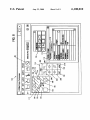
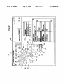
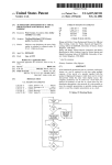
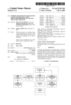
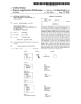
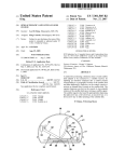
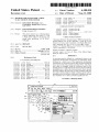
US006108010A
Ulllted States Patent [19]
[11] Patent Number:
Boezeman et al.
[45]
6,108,010
Date of Patent:
*Aug. 22, 2000
[54]
METHOD AND SYSTEM FOR A TRUESCALE MOTION PATH EDITOR
5,758,180
2,767,861
[75]
Inventors: John Junior Boezeman, Cary;
5,818,462 10/1998 Marks et al. .......................... .. 345/473
,793,382
both
Christopher
of NC- Joseph Paul Durham
[73]
0309373
Corp" Armonk’ NY‘
[*]
_
-
Notice.
8/1998
YeraZunis et a .
.
FOREIGN PATENT
Sato et a1.DOCUMENTS
............................. ..
Assignee: International Business Machines
-
5/1998 Duffy et a1. .......................... .. 395/806
6/1998 Kimura .......
..
3/1989
European Pat O?- -
02032156 13/133451 iEumpean Pat’ Off‘ '
apan
-
-
2258790
This patent issued on a continued pros-
ecution application ?led under 37 CFR
1.53(d), and is subject to the twenty year
12/1991
............................ ..
G06F 15/62
United Kingdom .
.
.
2303282 10/1993 Umted Kmgdom'
OTHER PUBLICATIONS
$226M germ provlslons of 35 USC‘
“Animated Software Documentation” IBM Technical Dis
(aX
closure Bulletin. vol. 34, No. 10A Mar. 1, 1992, pp. 27—28.
Tutorial 12: Curves and Controllers; 3—D Studio Max Tuto
[21l APP1- NO-I 08/896,817
[22] Filed:
JuL 18 1997
51
I
C17
rials, Autodesk, Inc., pp. 12—19 to 12—26 (Mar. 1996).
Chapter 19: Shaping Objects, Corel Draw4 User Manual,
’
G06T 13 00
[52] 61 Ci
[ ]
[58]
Corel Corporation, p. 118 (1993).
438 345/474
_' '
' """"" "
Field of Search .
Primary Examiner—A mis R. Jankus
’
..... .. 345/433, 438,
Attorney, Agent, or Firm—A. Bruce Clay; Myers Bigel,
Sibley & Sal-(W6C, RA~
345/473—475
[57]
[56]
ABSTRACT
References Cited
_
_
_
_
_
A movement path is de?ned for a multimedia ob]ect in an
US. PATENT DOCUMENTS
3’637’212
5,261,041
1/1972 Hurley "
application development environment. A multimedia object
is placed in a layout area of the application development
273/85 R
11/1993 Susman ....... ..
environment. A movement path is then speci?ed Within the
395/152
1
t
f
th
b-
t
-
- t-
d
-
Th
b-
1
d
. h h
t
5355 314
’
’
10/1994 Feigenbaum ..
. .
364/420
ayou .area or 60 16C usmgapom mg Wm‘
60 16C
may either be dragged along the movement path by the
5,425,139
6/1995 Williams et al.
395/152
5,510,995
4/1996 Oliver .............................. .. 364/474.24
Pointing W196 or 1n “'1 ‘la Poms my 656 we W“ t 6
5,572,639 11/1996 Gantt ..................................... .. 395/133
5 577 185 11/1996 Tunnell et aL
395/173
Pomtmg devlce to de?ne the moveme?“ Path- ,Once the Path
has been de?ned, the path may be easily modi?ed. The user
.
.
d
.
. d. .d
1
.
b
5:594:856
1/1997 Girard ......... ..
395/173
may 9199 or delete Points by Simply Selecting a 991m With the
5,619,628
4/1997 Fujita et a1_ __
395/127
pointing device for addition or deletion. In addition, the user
5,678,001
10/1997 Nagel et a1. .......................... .. 395/173
5,680,619
10/1997 Gudmundson et al. .............. .. 395/701
may combine two or more movement paths into one.
5,692,144 11/1997 Thrush .................................. .. 395/339
15 Claims, 9 Drawing Sheets
10o
\
UUM‘MWMW
/9a
/
l_lE1l><l
?le 5m 1w Layout Qp?ons \llndow /
R
s:
¢= 1: [:7 ‘66 a 69 We
i06_
220
4
@ <9
U.S. Patent
Aug. 22,2000
Sheet 1 of9
6,108,010
U.S. Patent
Aug. 22,2000
58BX0 25?l
x;
Q
90:/i
@
0%,
WMUw®©Ematv;
on;
\33?2mEM:520925»4m
o p\
Sheet 5 of9
6,108,010
8652. 3:05
80".
U.S. Patent
Aug. 22,2000
.mvE
0
Eta;
/
8&<Q250
Hv
Sheet 6 of9
6,108,010
52. .20..
30“
6,108,010
1
2
METHOD AND SYSTEM FOR A TRUE
SCALE MOTION PATH EDITOR
SUMMARY OF THE INVENTION
The present invention disclosed herein comprises a
method and system for de?ning a movement path of a
CROSS REFERENCE TO RELATED
APPLICATIONS
multimedia object Which greatly reduces problems associ
ated With the prior art. The present invention alloWs the
creation and modi?cation of a movement path Without the
This Application is related in subject matter to the fol
lowing Applications ?led concurrently hereWith and
need for a separate path dialog.
assigned to a common Assignee:
In accordance With one aspect of the present invention, a
movement path is de?ned for a multimedia object in an
Application Ser. No. 08/896,817 ?led by BoeZeman, et
10
al., entitled “Method and System for a True-Scale Motion
Path Editor to Create Motion Paths as Independent Entities”;
application Ser. No. 80/896,648 ?led by BoeZeman, et al.,
entitled “Method and System for a True-Scale Motion Path
Editor Using Time Segments, Duration and SynchroniZa
tion”; and application Ser. No. 08/896,818 ?led by
15
BoeZeman, et al., entitled “Method and System for a True
Scale Motion Path Editor Using Proximity Detection/
Reaction and Event Generation”.
The foregoing applications are incorporated herein by
20
application development environment. A multimedia object
is placed in a layout area of the application development
environment. A movement path is then speci?ed Within the
layout area for the object using a pointing device. The object
may either be dragged along the movement path by the
pointing device or individual points may be selected With the
pointing device to de?ne the movement path.
Once the path has been de?ned, the path may be easily
modi?ed. The user may add or delete points by simply
selecting a point With the pointing device for addition or
deletion. In addition, the user may combine tWo or more
reference.
movement paths into one.
FIELD OF THE INVENTION
This invention relates in general to computer softWare,
and in particular to a method and system for de?ning the
25
movement path of a multimedia object in an application
development environment.
thus, providing greater ?exibility for the developer.
BACKGROUND OF THE INVENTION
In a multimedia application development environment,
30
on the right side of the page. Using the knoWn techniques,
junction With the accompanying draWings, in Which:
35
the assignment of a motion path to a part is tedious. In
addition, the knoWn techniques have limited ?exibility and
require construction separate from the part layout area. Once
constructed, it is dif?cult to modify the path.
One type of path de?nition is found in, for example,
Premier by Adobe. To construct a path for an obj ect/part, the
Without the perspective of the actual environment including
FIG. 2 is a graphical representation of a multimedia parts
40
path utiliZing various anchor points;
FIG. 7 illustrates the use of the present invention to add
or delete an anchor point to a path;
FIG. 8 illustrates use of the present invention to de?ne a
curved path; and
50
complex layouts.
Another type of path de?nition can be found in Director
by Macromedia. This type of path de?nition alloWs the use
of the actual layout area for construction but also requires
FIGS. 3,4 and 5 are graphical representations of the
multimedia editor of FIG. 1 utiliZing a path editor in
FIG. 6 illustrates use of the present invention to de?ne a
45
and run a test. If the path does not Work as expected, the user
again. This is aWkWard and time consuming, especially in
editor;
accordance With the present invention;
lack of true-scale surrounding parts. Thus, the user must
create the path and then assign it, return to the layout area
must return to the separate path de?nition WindoW and try
FIG. 1 is a pictorial representation of a data processing
system Which may be utiliZed to implement a method and
system of the present invention;
user must exit the layout area and enter a separate WindoW.
Then, the user can draW a path for the part using a pointing
device. There is no one-to-one scale and the path is draWn
BRIEF DESCRIPTION OF THE DRAWINGS
For a more complete understanding of the present inven
tion and for further advantages thereof, reference is noW
made to the folloWing Detailed Description taken in con
users often Want to assign a path along Which the part Will
move to give the application special effects. For example, a
user might Want to display an animation of a bird appearing
on the left edge of a page and ?ying across the page to exit
The present invention provides the technical advantage of
being able to simply and intuitively create and modify a
movement path for a multimedia object in an application
development environment. Previously created and stored
paths may be reused and or added to neWly created paths,
FIG. 9 illustrates the use of the present invention to join
a prede?ned and stored path to a neWly created path.
DETAILED DESCRIPTION OF THE
INVENTION
complex arrangements of multiple parts of any type using
Referring to FIG. 1, there is depicted a graphical repre
sentation of a data processing system 8, Which may utiliZed
to implement the present invention. As may be seen, data
processing system 8 may include a plurality of netWorks,
such as Local Area Networks (LAN) 10 and 32, each of
Which preferably includes a plurality of individual comput
ers 12 and 30, respectively. Of course, those skilled in the art
Will appreciate that a plurality of Intelligent Work Stations
(IWS) coupled to a host processor may be utiliZed for each
such netWork. As is common in such data processing
systems, each individual computer may be coupled to a
storage device 14 and/or a printer/output device 16 and may
multiple paths.
be provided With a pointing device such as a mouse 17.
55
the use of a “score” area. The user must drag the part to the
start time in the score. Then the user must drag the part to
the next movement position in the layout are folloWed by
another dragging to the score area for the time it should
appear in that position. Once these steps have occurred from
start point to ?nish point, the score area is highlighted and
the placement is made on the layout area. Thus, this method
60
can also be sloW and tedious.
Thus, there is a need for a method and system for path
de?nition that is quick and easy to use, especially for
65
6,108,010
3
4
The data processing system 8 may also include multiple
mainframe computers, such as mainframe computer 18,
Which may be preferably coupled to LAN 10 by means of
98 on the main toolbar or by selecting “Motion Path Editor”
via the appropriate menu choice. The path WindoW 114 is
provided With a plurality of buttons and tools (Which Will be
communications link 22. The mainframe computer 18 may
subsequently described in greater detail), including a
also be coupled to a storage device 20 Which may serve as
“Record” push-button 130 and a “Join” push-button 132. In
addition, all the parts/images Within the layout area 102 are
remote storage for LAN 10. Similarly, LAN 10 may be
coupled via communications link 24 through a sub-system
control unit/communications controller 26 and communica
tions link 34 to a gateWay server 28. The gateWay server 28
is preferably an IWS Which serves to link LAN 32 to LAN
slightly ghosted When the motion path WindoW 114 is ?rst
displayed, as indicated by the diagonal lines appearing
therethrough.
10
10.
With respect to LAN 32 and LAN 10, a plurality of
documents or resource objects maybe stored Within storage
device 20 and controlled by mainframe computer 18, as
resource manager or library service for the resource objects 15
thus stored. Of course, those skilled in the art Will appreciate
that mainframe computer 18 may be located a great geo
graphic distance from LAN 10 and similarly, LAN 10 may
be located a substantial distance from LAN 32. For eXample,
LAN 32 may be located in California While LAN 10 may be
located Within North Carolina and mainframe computer 18
may be located in NeW York.
SoftWare program code Which employs the present inven
tion is typically stored in the memory of a storage device 14
20
Referring to FIG. 4, the user has selected an object, for
eXample, the square 104, to Which a path Will be assigned.
As shoWn in FIG. 4, the square 104 has become unghosted
(shoWn Without diagonal lines). There are tWo methods for
creating the motion path for square 104. First, the user can
press the record push-button 130, and While holding the
mouse button doWn, drag the square 104 manually in the
layout area 102 to de?ne a path. In the second method, the
user can manually de?ne individual points along Which the
square 104 Will folloW for its path.
Referring to FIG. 5, an eXample of the manual drag
technique to assign a path is shoWn. The user presses the
Record push-button 130, and then places a cursor 150 over
the object to be moved, for eXample, the square 104, and
drags the object along a path (shoWn as line 105) of the
desired movement. When the user has reached the point at
of a stand alone Workstation or LAN server from Which a 25 Which he/she Would like the path to end, the user releases the
developer may access the code for distribution purposes, the
softWare program code may be embodied on any of a variety
of knoWn media for use With a data processing system such
mouse button and the path “record” activity ceases. When
set into motion, the square 104 Will then move along the path
105 as draWn.
as a diskette or CD-ROM or may be distributed to users from
Referring to FIG. 6, the setting of anchor points technique
30
a memory of one computer system over a netWork of some
is shoWn. The user can de?ne as many anchor points as
type to other computer systems for use by users of such other
desired, for eXample, anchor point 160 and anchor point 162
systems. Such techniques and methods for embodying soft
With the initial anchor point de?ned as the physical center
Ware code on media and/or distributing softWare code are
Well-knoWn and Will not be further discussed herein.
Referring to FIG. 2, a graphical representation of a
multimedia part editor is shoWn in WindoW 100. Within the
part editor 100 there appears a layout area, generally indi
cated by reference numeral 102, in Which a plurality of
multimedia objects/parts, for example, square 104, triangle
106 and circle 108, are positioned for manipulation. A
(not shoWn) of the object. A connecting line is automatically
35
action completes the path. When set in motion, the object
(square 104) Will then move along the path as de?ned by the
40
anchor points.
45
as identi?ed by line 170 from the square 104 through anchor
points 172, 174 and 176, the user decides that the path 170
needs to be modi?ed. To add a point on the path 170, the user
selects an anchor point “Add” tool 204 from the path editor
Referring to FIG. 7, having already de?ned a motion path
palette WindoW 110 and a Details WindoW 112 are also
provided. The palette WindoW 110 contains a collection of
parts available for use in the current application being
developed. These may include multimedia parts(image,
sound, animation, etc) and/or controls (buttons, labels,
WindoW 114 and moves the cursor 150 over the desired
location for a neW anchor point 171 and presses the mouse
listboXes, etc).
The Details WindoW 112 is used to modify and customiZe
the speci?c parts used in the current application and add
logic betWeen parts. A Properties tab 113 in the Details
WindoW 112 provides a method to modify the parts by
alloWing the user to customiZe speci?c characteristics of
parts in the current application. For example, the picture
property of an image part can be any source ?le (in the
correct format) that the user desires. A Connections tab 115
of the Details WindoW 112 provides a method to add logic
button. This adds the neW anchor point 171 on the path 170.
To delete an eXisting point from the path 170, the user selects
the anchor point “Delete” tool 208 from the path editor
WindoW 114, moves the cursor 150 over the eXisting point to
be deleted and presses the mouse button. This deletes the
indicated anchor point from the path 170.
Referring to FIG. 8, a technique for curving a path is
55
format. For eXample, a user can add logic betWeen a button
and a sound ?le so that When the button is clicked, the sound
handle 177 is dragged “clockWise”). Alternatively, the user
60
sound play”.
make a curve point anchor point into a straight line anchor
point, the user can select the curve point anchor point on the
Referring to FIG. 3, upon pressing a motion path button
apply the path to and then pressing the motion path button
can select the anchor point and press an anchor point “curve
point” tool 210 in the path editor WindoW 114. Similarly, to
98 on a main toolbar or by selecting “Motion Path Editor”
(not shoWn) via an appropriate menu choice, a path editor
WindoW 114 appears adjacent to the layout area 102. Apart
speci?c path can also be created by ?rst selecting a part to
illustrated. The user de?nes a curve by simply holding and
dragging the mouse as the anchor point is being laid,
producing an anchor point With tWo handles 175 and 177
Which the user can de?ne and smooth the curve (as shoWn,
betWeen parts in the “part, event—part, action/property”
?le Will play. This connection Would read: “button clicked
draWn betWeen anchor points as each subsequent anchor
point is de?ned. To indicate the end of the path, the user
double-clicks the mouse at the location of the end point, this
65
layout area 102 and press an anchor point “straight line” tool
206 on the path editor WindoW 114.
Referring to FIG. 9, a technique is illustrated for joining
tWo or more movement paths . Any tWo or more paths can
6,108,010
6
5
be joined by selecting an end anchor point, for example,
means for displaying the speci?ed plurality of movement
paths in the layout area; and
anchor point 220, of a ?rst path 221 to be joined and an end
anchor point 222 of a second path 224 and pressing the
“Join” button 132 on the path editor WindoW 114. Aposition
means for graphically revising the speci?ed plurality of
movement paths displayed in the layout area by joining
of the tWo points is averaged in both a horizontal and a
vertical direction and one point is created from the tWo at the
resulting position. The user can also select the tWo anchor
at least tWo of the plurality of movement paths to
provide a single movement path for the object, Wherein
the step of joining comprises averaging the positions of
points (points 220 and 222) to be joined by clicking the
tWo corresponding points on the at least tWo paths so as
mouse and dragging a dynamically siZed boX around the tWo
points and pressing the “Join” button 132 on the path editor
WindoW 114.
Thus the present invention offers strong advantages over
traditional motion path editors. As described herein, the
present invention alloWs the de?nition of a true-scale path
Without requiring the use of a separate path editor dialog.
to provide a third point Which joins the at least tWo
10
7. The system of claim 6, Wherein said means for speci
fying further comprises:
means for dragging said object along said movement path
With said pointing device.
8. The system of claim 6, Wherein said means for speci
Also provided herein are easy to use methods for path
fying further comprises:
(including curved paths) construction, modi?cation, and
joining.
Although the present invention has been described With
respect to a speci?c preferred embodiment thereof, various
changes and modi?cations may be suggested to one skilled
20
in the art and it is intended that the present invention
encompass such changes and modi?cations as fall Within the
scope of the appended claims.
What is claimed is:
1. A method of de?ning a movement path of a multimedia
25
object in an application development environment, compris
ing the steps of:
Within said layout area for said object With a pointing
device Without the need to enter a separate layout editor
in an area separate from said layout area;
35
the layout area; and
40
said layout area;
computer readable means for displaying the speci?ed
plurality of movement paths in the layout area; and
computer readable means for graphically revising the
layout area by joining at least tWo of the plurality of
movement paths to provide a single movement path for
provide a third point Which joins the at least tWo paths.
2. The method of claim 1, Wherein said step of specifying
45
the object,
Wherein the step of joining comprises averaging the posi
tions of tWo corresponding points on the at least tWo paths
so as to provide a third point Which joins the at least tWo
3. The method of claim 1, Wherein said step of specifying
paths.
further comprises:
selecting individual points With said pointing device
Which Will de?ne said movement path.
4. The method of claim 3, further comprising the step of:
adding additional points to said path after said path has
been de?ned.
ronment;
computer readable means for graphically specifying a
plurality of movement paths Within said layout area for
said object With a pointing device Without the need to
speci?ed plurality of movement paths displayed in the
responding points on the at least tWo paths so as to
further comprises:
dragging said object along said movement path With said
pointing device.
computer readable means for placing a multimedia object
in a layout area of the application development envi
enter a separate layout editor in an area separate from
graphically revising the speci?ed plurality of movement
paths displayed in the layout area by joining at least tWo
of the plurality of movement paths to provide a single
movement path for the object; Wherein the step of
joining comprises averaging the positions of tWo cor
has been de?ned.
11. A computer program product recorded on a computer
readable medium for de?ning a movement path of a multi
comprising:
30
graphically specifying a plurality of movement paths
displaying the speci?ed plurality of movement paths in
means for selecting individual points With said pointing
device Which Will de?ne said movement path.
9. The system of claim 8, further comprising:
means for adding additional points to said path after said
path has been de?ned.
10. The system of claim 8, further comprising:
means for deleting points from said path after said path
media object in an application development environment,
placing a multimedia object in a layout area of the
application development environment;
paths.
55
5. The method of claim 3, further comprising the step of:
deleting points from said path after said path has been
12. The program product of claim 11, Wherein said
computer readable means for specifying further comprises:
computer readable means for dragging said object along
said movement path With said pointing device.
13. The program product of claim 11, Wherein said
computer readable means for specifying further comprises:
computer readable means for selecting individual points
With said pointing device Which Will de?ne said move
6. Asystem for de?ning a movement path of a multimedia
object in an application development environment, compris
mg:
means for placing a multimedia object in a layout area of
the application development environment;
means for graphically specifying a plurality of movement
paths Within said layout area for said object With a
pointing device Without the need to enter a separate
layout editor in an area separate from said layout area;
60
ment path.
14. The program product of claim 13, further comprising:
computer readable means for adding additional points to
said path after said path has been de?ned.
15. The program product of claim 13, further comprising:
computer readable means for deleting points from said
path after said path has been de?ned.
*
*
*
*
*