1
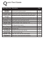
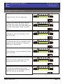
Progr a m m i n g M a n u a l
2x
2x
RINS1210-5
EN50131-1
Grade 2 Compliance
Q
uick Find Guide
Main Menu Item Description
Software
Revision
Wiring Choice
Change Inputs
Assign Keypads/
Readers
System Displays
Change Timers
Set Date & Time
Exit Modes
Change Codes
Page
Control panel version number
10
Double Pole, DEOL 4K7,2K2 or 4K7, 4K7.
Inputs types, part sets, attributes and input names
10
11
Keypad and reader addresses and keypad names
12
Sign on message and ‘Display when set’ function.
Entry, Exit, Siren Time, Re-arm no, Fire Siren Time
Year, Month, Day, Hours and Minutes
Timed, Final Door, Timed/Final
Master Manager Code, Engineers Code
Entry, Exit, Alarm, Fire, 24hr, Chime, Intelligent Set,
Volume Control
E/E Keypads Only option.
Alarm Response First Alarms for each level set
Change Outputs Bell, Strobe, PGM, and XPGMs outputs
Intelligent Set Intelligent set
13
13
14
14
15
16
17
17
18
Site Options
Strobe at Set and 2 Key Hold Up
18
Review Logs
The control panel logs
19
Walk Test, Test Siren and Test Outputs
20
View PSU’s, View Inputs and Calibration
22
Engineer Tests
Diagnostics
C
ontents Page
Contents Page
3
Introduction
4
Descriptions
5
The Contemporary Keypad
6
The Contemporary Keypad
7
Entering the Keypad Menu
Powering Up
7
8
Addressing Keypads
Engineering Menu
8
9
Entering the Engineering Menu
Exiting the Engineering Menu
Software Revision
Wiring Choice
Change Inputs
Assign Keypads/Readers
System Displays
Change Timers
Set Date and Time
Exit Modes
Change Codes
Change Codes Continued...
Volume Control
Alarm Responses
Change Outputs
Change Outputs continued...
Intelligent Set
Site Options
Site Options continued...
Review Logs
Engineer Tests
Engineer Tests Continued...
Diagnostics
Clean Start
Appendix A
9
9
10
10
11
12
13
13
14
14
15
16
16
17
17
18
18
18
19
19
20
21
22
23
24
Input Types
Input Attributes
Appendix B
24
24
25
Output Types
Appendix C
25
26
Defaults
Appendix D
26
27
Fault Codes
Castle Care-Tech
27
Page:3
I
ntroduction
The EURO mini offers the reassurance and peace of mind for protecting your
customer’s property whilst meeting all the relevant standards.
Programming of the EURO mini is the same as EURO MERiDIAN panels so this is
the perfect alternative for your smaller installations.
The slim contemporary LCD keypad with full English text operates the EURO mini
and up to 4 of these keypads can be connected to a system.
Castle Care-Tech Limited is a UK based designer of high technology control
equipment for intruder alarms and as a leading innovator, Castle has won
numerous awards for products and innovation in recent years.
The EURO mini consists of:
4 level sets
10 End of Line/9 Double Pole Zones
Up to 4 keypads/3 readers can be connected
8 Outputs (Bell, Strobe, Speaker, Programmable, and 4 Shared with Inputs)
4 Fuses (Bell, Aux, RS485 and Battery)
Case Tamper and SAB Tamper
500 Mandatory and 200 Optional log events
32 Codes (30 User, 1 Master Manager and 1 Engineer)
Different alarm responses may be programmed
Keypad Prox/Prox reader may be connected.
Page:4
Castle Care-Tech
D
escriptions
This chapter outlines the features and functionality the EURO mini can offer:
Level Set System:
The EURO mini can operate up to 4 part sets: A, B, C, and D. An example of how
these can be programmed are as follows:
Part
Part
Part
Part
Set
Set
Set
Set
A: (All) All house is set.
B: (Bedtime) Downstairs is set, Upstairs is unset
C: (Pet) Kitchen unset (for a pet), rest of house is set.
D: (Garage Only) Garage set, rest of house unset.
These are programmed in the function ‘Change Inputs’, and user codes may also
be programmed in different part sets. Please see the user manual for this.
Note: After a code is entered, once the final door or exit time has expired, a settle
time of 10 seconds will take place before the system is finally set.
Flexi Set
Flexi set can be selected for each individual user code which is used so the user
selects which part sets to set/unset (depending on the part sets the codes are
assigned to). If Flexi-set is set as ‘No’ then once a code is entered, the EURO mini
will automatically set the assigned part set. Please note that user codes can only
be programmed in the master manager menu (see the user manual).
Emergency Alarms
The emergency buttons for the EURO mini consist of 2 buttons being pressed
simultaneously. These are buttons 1 and 7. At default, these are disabled, they will
have to be enabled in the function ‘Site Options’.
Automatic Re-arming
When the bell time expires (default is 4 minutes), the EURO mini will automatically
rearm, and omit any circuits that are in open at that point. The number of times it
will re-arm after an alarm is programmable in ‘Change Timers’.
Inputs and Outputs
The EURO mini consists of 10 inputs (or zones) that are fully programmable for
detectors, door contacts, fire alarms, etc. Each input may be programmed as
normally open, or with a chime, or the input can be programmed as omittable so
the user has control on whether or not the input needs to be active.
Inputs 7 to 10 can be used as outputs (instead of inputs), thus giving the total of
7 outputs on the system. Outputs are used to connect to external devices such as
signalling equipment or sirens. If inputs 7 to 10 are all used as outputs then only
a total of 6 inputs can be used. For all programming please see either ‘Change
Inputs’ or ‘Change Outputs’.
Faults
If any faults occur on the EURO mini, it will be shown on the LCD keypad with a
short description of the problem. For more information please see page: 26.
Castle Care-Tech
Page:5
T
he Contemporary Keypad
Functionality
The Contemporary Keypad has a 32 character LCD display, with encapsulated
backlit keys and 5 status LEDs.
EuroMini 10V6.e
Time
10:01 c
The operation of each key are described below:
Keys
Description
Used to enter codes and program names for
Numerical inputs,keypads,display etc.
Selects menus, and any attributes in the menus. Used to set the
YES
panel if flexi-set is enabled (see the master manager menu).
Moves forward to the next main menu item, clears any faults,
NO
and resets the control panel after an alarm.
Used to exit Engineering Menu (from a main menu) and to select
A
part set A when setting.
Moves backwards in the main menu and sub menus and used to
B
select part set B when setting.
Selects chime on/off, displays additional information in the log,
C
and used to select part set C when setting.
Moves forwards in the main menu, toggles between menu choices, enters the master manager menu, and used to select part set
D
D when setting. Enters the keypad menu.
The status LEDs are as follows (left to right)
LED
Description
Alert
Orange. Used to indicate any alerts on the system.
Alarm
Indicates that an alarm condition has occurred
Tamper
Indicates a tamper has occurred
Fault
Indicates a fault has occurred
Unset
Illuminates briefly after the system has been unset
NOTE: If a EUR-068 has been purchased, the keypad has the prox enabled which
allows arming/disarming via card/tag.
Page:6
Castle Care-Tech
T
he Contemporary Keypad
Text Programming
Text may be programmed for input names, for the ‘sign-on’ message, and to
identify the level set / unset. Each keypad key is allocated characters as shown
below:
Press the relevant key the appropriate number of times - e.g. for the letter ‘k’
press the 5 key twice, or for the letter ‘s’ press the 7 key four times.
Other operations of each key are as follows:
Keys
A
B
C
D
0
1
Description
Makes the character into a capital
Moves the cursor to the left
Deletes the letter
Moves cursor to the right
Adds a space
Adds punctuation
Entering the Keypad Menu
Press and hold the D key until ‘SECURITY CODE’ is displayed. Enter ‘2000’.
Menu
Address
Language
Keyclick Volume
Tag Volume
Master Volume
Tag ID
Factory Reset
Backlight Force
PA/Fire Timer
Castle Care-Tech
Description
Address of the keypad
Language of the keypad
0 = Silent, 7 = Loudest
0 = Silent, 7 = Loudest
0 = Silent, 7 = Loudest (overall volume for keypad)
Present a tag for the id (only applicable to EUR-068)
Enter ‘2000’ to reset all keypad functions to default
0 = Backlight off (until key pressed/entry route active)
1 = Backlight on all time
How many seconds keys 1 and 7 must be held for a PA to
activate.
Page:7
P
owering Up
Initial State
Once everything is connected to the EURO mini (see the installation manual),
power up the EURO mini.
After inital power up, the following
will first be displayed (may differ
depending on version numbers)
After a couple of seconds, the EURO
mini will ask for the address of the
first keypad. Enter ‘00’ and press the
‘YES’ key.
Use the ‘YES’ key to scroll through
the different options (Keyclick
volume, master volume etc)
Once all options have been chosen,
press the ‘A’ key to ‘Activate’ the
keypad.
The ‘day’ screen will be shown.
EURO
EURO KEYPAD
KEYPAD
EURO
KEYPAD
V5.03
10.10/2005
EURO KEYPAD
V5.03
V5.03 10.10/2005
10.10/2005
V5.03 10.10/2005
ADDRESS
ADDRESS
ADDRESS
LANGUAGE
LANGUAGE
LANGUAGE
LANGUAGE
English
English
LANGUAGE
English
English
English
[--]
[--]
[--]
[--]
[00]
[00]
[00]
[00]
[00]
KEYCLICK VOLUME
KEYCLICK VOLUME
KEYCLICK
[7]
KEYCLICK VOLUME
VOLUME
KEYCLICK VOLUME
[7]
[7]
[7]
[7]
EuroMini 10V6.e
EuroMini
10V6.e
Time
EuroMini
EuroMini 10V6.e
10V6.e
EuroMini
10V6.e
Time
Time
Time
Addressing Keypads
To address further keypads on the system, press and hold the ‘D’ key until
‘KEYPAD CODE’ is displayed. Enter ‘2000’. This will take you to the keypad
screens described above.
Any keypad that is new to the EURO mini must first be initialised with this
function, and then enabled in the Engineering menu on the master keypad
(address 00). The function to do this is ‘Assign Keypads’.
Page:8
Castle Care-Tech
E
ngineering Menu
Entering and Exiting
Entering the Engineering Menu
When the time is displayed on the
main screen, enter the Engineers
code (default is 1111)
EuroMini
EuroMini 10V6.e
10V6.e
Time
10:01
EuroMini
10V6.e
Time
10:01 c
c
Time
10:01 c
‘SET/UNSET SYSTEM?’ will be
displayed, this can be used to set/
unset the EURO mini without a user
code. Press the NO key.
EuroMini 10V6.e
EuroMini 10V6.e
Time/ UNSET
10:01 c
SET
Time
10:01 c
SET / UNSET
SYSTEM?
SYSTEM?
‘SOFTWARE REVISION?’ will be
displayed, and the panel is now in
the Engineering Menu. Use the ‘NO’
and ‘B’ keys to scroll forward and
backward through the menu.
SET / UNSET
SOFTWARE
SET
/ UNSET
SOFTWARE
SYSTEM?
REVISION?
SYSTEM?
REVISION?
Please note that all Fire and Hold Up alarms
are suppressed in the
SOFTWARE
CHANGE OUTPUTS?
SOFTWARE
REVISION?
CHANGE OUTPUTS?
OUTPUTS?
Engineering Menu. CHANGE
REVISION?
To Enter
EngineeringMenu
Menu:
Exiting
thethe
Engineering
When a main menu item is displayed
in Engineers (capital letters), press
the ‘A’ key to exit the Engineering
Menu.
CHANGE OUTPUTS?
EXIT ENGINEERS
ENGINEERS
EXIT
CHANGE
MENU? OUTPUTS?
MENU?
OR
Using the ‘B’ or ‘NO’ keys, scroll to
‘EXIT Engineering Menu’. Press the
‘YES’ key.
Castle Care-Tech
EXIT ENGINEERS
MENU?
EXIT ENGINEERS
MENU?
Page:9
E
ngineering Menu
Software Revision
Wiring Choice
Software Revision
Software Revision identifies the software version number, this is may be asked for
by the Castle Care-Tech Customer Support team.
Use the ‘B’ and ‘NO’ keys to scroll
to ‘SOFTWARE REVISION’. Press the
‘YES’ key.
The Software Revision will be
displayed. Press ‘YES’ to exit.
Wiring Choice
SOFTWARE
REVISION?
SOFTWARE
SOFTWARE
SOFTWARE
Rev V1.00e
V1.00e
Rev
REVISION?
REVISION?
REVISION?EuroMini
EuroMini
WIRING CHOICE?
Rev
Rev V1.00e
V1.00e
WIRING
CHOICE?
EuroMini
Selects the EURO mini to perform as a double pole system,EuroMini
or a double end of line
system (either 4K7 alarm, 2K2 tamper, or 4K7 alarm, 4K7 tamper). All wiring
diagrams can be found in the installation manual.
Use the ‘B’ and ‘NO’ keys to scroll to
‘WIRING CHOICE’. Press the ‘YES’
key.
Use the ‘D’ key to select:
0 = Double Pole
1 = DEOL 4K7 Alarm, 2K2 Tamper
2 = DEOL 4K7 Alarm, 4K7 Tamper
Once the relevant wiring choice has
been selected, press the ‘YES’ key.
Detection Mode
WIRING
CHOICE?
DEOL 2K2/4K7
WIRING
CHOICE?
Detection
Mode[1]
DEOL 2K2/4K7 [1]
Detection Mode
Detection
Mode
DEOL 2K2/4K7
Detection
Mode[1]
Detection
Mode
DEOL
DEOL 2K2/4K7
2K2/4K7 [1]
[1]
DEOL 2K2/4K7 [1]
Detection
Detection Mode
Mode
DEOL
DEOL 2K2/4K7
2K2/4K7 [1]
[1]
PLEASE NOTE: If Double Pole has been selected the jumper above input
1 on the printed circuit board must be removed, or if resistors are used,
the jumper must be present. Please see the installation manual for more
information
Page:10
Castle Care-Tech
E
ngineering Menu
Change Inputs
Change Inputs
‘Change Inputs’ programs all 10 inputs. For all descriptions of input types and
attributes please see page 23. If ‘Input is used as an output’ is shown on inputs 7
to 10, then an output is already programmed (see Change Outputs page 17).
Use the ‘B’ and ‘NO’ keys to scroll to
‘CHANGE INPUTS’. Press the ‘YES’
key.
Use the ‘B’ or ‘D’ keys to choose the
input number. Press the ‘YES’ key.
Select the input type using the ‘B’
and ‘D’ keys. Press the ‘YES’ key.
For a full list of the inputs and
descriptions please see page 23.
Select the level set that the input
will be in. There are four level sets
to choose from: A, B, C, D. Press the
‘YES’ key.
Press the ‘YES’ key to go into Input
Attributes.
Chime, Omittable, Double Knock,
and Normally Open. Select ‘Yes’ or
‘No’ to each attribute by using the ‘D’
key. Press the ‘YES’ key.
To create an Input name, press the
‘YES’ key and use the letters on the
buttons to create a name. Press the
‘YES’ key.
Castle Care-Tech
CHANGE INPUTS?
CHANGE INPUTS?
INPUTS?
CHANGE
CHANGE INPUTS?
Input
Input Number
Number
Input
Number
Input
Number
Input Number
Input
Input
Input
Input
Final
Input
Final
Final
Final
Final
Input
Type
Type
Type
Type
Exit
Type
Exit
Exit
Exit
Exit
Type
Final Exit
Input
Input
Input
Input
Input
Input
Input
[01]
[01]
[01]
[01]
[01]
OR
OR
OR
OR
THEN
THEN
THEN
THEN
OR
THEN
[07]
[07]
[07]
[07]
[07]
[07]
Active
Active In
In
Active
In
Active
In
[A
Active
[AIn
[A
Active
In
[A
[A
Active In
[A
OR
OR
OR
OR
OR
THEN
THEN
THEN
THEN
THEN
OR
THEN
]
]
]
]
]
]
THEN
THEN
THEN
THEN
THEN
THEN
Input Attributes?
Input Attributes?
Input Attributes?
Input Attributes?
Input Attributes?
Chime
Chime
No
No
Chime
Chime
Chime
No
Chime
No
No
No
[0]
[0]
[0]
[0]
[0]
[0]
TO CHOOSE THEN
TO CHOOSE THEN
TO
CHOOSE THEN
THEN
TO CHOOSE
TO
CHOOSE THEN
TO CHOOSE THEN
Input Name?
Input Name?
Input
Input Name?
Name?
Input
Name?
Input
Name?
Page:11
E
ngineering Menu
Assign Keypads
Assign Keypads/Readers
Keypads can be allocated to different part sets and up to four keypads can be
added to the EURO mini.
For Example, if 2 keypads are installed on the system (one upstairs, one downstairs), the location of the keypad downstairs will be A (for a full set), and the
location of the keypad upstairs will be B (for a part set).
Use the ‘B’ and ‘NO’ keys to scroll to
‘ASSIGN KEYPADS’. Press the ‘YES’
key.
ASSIGN
KEYPADS/
ASSIGN
ASSIGN KEYPADS/
KEYPADS/
READERS?
ASSIGN KEYPADS/
READERS?
READERS?
ASSIGN
KEYPADS/
READERS?
READERS?
Use the ‘B’ or ‘D’ keys to select the
address of the keypad (0-3)
Address
Address
Address
Address
[0]
[0]
[0]
[0]
THEN
THEN
THEN
THEN
THEN
OR
OR
OR
OR
OR
To install the keypad press ‘1’. To
install a reader press ‘2’
Press the ‘YES’ key.
Type
Type
Type
Type
Keypad
Keypad
Type
Keypad
Keypad
Type
Keypad
Keypad
Select the location of the keypad/
reader - i.e. level set A, B, C or D
(the default is A). Press the ‘YES’
key.
Keypad
Keypad
Keypad
Keypad
Keypad
Keypad
To create a name for the keypad,
press the ‘YES’ key.
Use the letters on the buttons to
create a name. Press the YES key.
Page:12
[0]
[0]
[0]
[0]
[0]
[0]
TO
TO
TO
TO
TO
TO
CHOOSE
CHOOSE
CHOOSE
CHOOSE
CHOOSE
CHOOSE
THEN
THEN
THEN
THEN
THEN
THEN
Location
Location
Location
[A
]
Location
Location
[A
]
[A
]
[A
]
Location
[A
]
[A
]
THEN
THEN
THEN
THEN
THEN
THEN
Keypad
Keypad
Keypad
Keypad
Keypad
Name?
Name?
Name?
Name?
Name?
Keypad
Keypad
Keypad
Keypad
Keypad
Keypad
Keypad
Keypad
Keypad
Name
0
Name
Name
Name
0
0
Name
0
0
Castle Care-Tech
E
ngineering Menu
System Displays
Change Timers
System Displays
The text string on the keypad that is displayed when you exit the Engineering
Menu can be changed within ‘System Displays’. The function ‘Display When Set’
will display which part set is set on the keypad.
Use the ‘B’ and ‘NO’ keys to scroll to
‘SYSTEM DISPLAYS’. Press the ‘YES’
key.
Enter the Sign On Message for the
main display. Press the ‘YES’ key.
SYSTEM
SYSTEM DISPLAYS?
DISPLAYS?
Sign On Message
EuroMini 10V6.e
10V6.e
EuroMini
SYSTEM DISPLAYS?
SYSTEM DISPLAYS?
If the part set that is set needs to be
shown when the system is set, press
the ‘D’ key to scroll to ‘yes’.
Press the ‘YES’ key.
Change Timers
Display
When
Set
Display When
When Set
Set
Display
No
[0]
No
[0]
No
[0]
Sign On Message
Sign On Message
EuroMini 10V6.e
EuroMini 10V6.e
TO CHOOSE THEN
TO CHOOSE
CHOOSE THEN
TO
THEN
CHANGE TIMERS?
CHANGE TIMERS?
TIMERS?
CHANGE
The following timers can be changed:
Entry Time/Exit Time: 0-255 seconds.
Siren Time (Cut off time for a siren): 2-15 minutes. Display
When Set
Display When Set
No
[0]
Fire Siren Time (Cut off time for a fire alarm): 1-99 No
Minutes: [0]
A Entry Time
Re-arm Numbers (automatic rearming after an alarm):
0-9
(9
means always)
A Entry
Entry Time
Time[030]
A
[030]0
TO CHOOSE
THEN
Double Knock (Length of time between filter period of inputs):
75 seconds
[030]
TO CHOOSE
THEN
Use the ‘B’ and ‘NO’ keys to scroll to
‘CHANGE TIMERS’. Press the ‘YES’
key.
Enter the desired choice for each of
the entry, exit and siren times for
each level set. Then enter the re-arm
number and the fire siren time. To
move through each option, press the
‘YES’ key.
Castle Care-Tech
CHANGE TIMERS?
CHANGE TIMERS?
A Entry Time
A Entry Time
[030]
[030]
Page:13
E
ngineering Menu
Set Date & Time
Exit Modes
Set Date and Time
Sets the date and time for the EURO mini.
Use the ‘B’ and ‘NO’ keys to scroll to
‘SET DATE & TIME’. Press the ‘YES’
key.
Enter the Year, Month, Day, Hours
and Minutes. Press the ‘YES’ key.
Exit Modes
SET DATE & TIME?
Year (00-99)
(00-99)
Year
[07]
[07]
SET DATE & TIME?
EXIT MODES?
EXIT MODES?
SET DATE & TIME?
Timed, Final Door or Timed/Final Door can be selected for the Exit procedure of
all level sets.
Timed: The EURO mini will set when the exit time expires (programmed in
‘Change Timers’)
A Exit Mode
Final Door: The EURO mini will set when the final exit
door
has
been opened and
Timed
[0]
Year
(00-99)
A
Exit
Mode
Year (00-99) [07]
Timed
[0]
closed.
[07]
Timed/Final: The EURO mini will set either when the final exit door
has
been
TO CHOOSE
THEN
TO CHOOSE
THEN
opened and closed, or the exit time has expired (Final Exit overrides
Timed)
Use the ‘B’ and ‘NO’ keys to scroll to
‘EXIT MODES’. Press the ‘YES’ key.
Use the ‘D’ key to select:
0 = Timed
1 = Final Door
2 = Timed/Final (final will override
timed). Press the ‘YES’ key.
Page:14
EXIT MODES?
EXIT MODES?
A Exit Mode
Timed
Timed
[0]
[0]
TO CHOOSE
CHOOSE THEN
THEN
TO
Castle Care-Tech
E
Change Codes
ngineering Menu
Change Codes
The master manager code and the engineer code can be changed here. User
codes can only be changed from the master manager mode - please see the user
manual.
Use the ‘B’ and ‘NO’ keys to scroll
to ‘CHANGE CODES’. Press the ‘YES’
key.
Press the ‘YES’ key to change the
master manager code.
Press the ‘C’ key to clear the existing
code and enter the new one using
the numeric keys. Press the ‘YES’
key.
Select the level set that the master
manager code will be able to
operate. There are four level sets to
choose from: A, B, C, D.
CHANGE CODES?
CHANGE CODES?
CODES?
CHANGE
CHANGE CODES?
Change
Change Master
Master
Change
Master
Change
Master
Manager
Manager Code?
Code?
Manager
Code?
Manager
Code?
Change Master
Manager Code?
Master
Master
Master
Master
Code
Master
Code
Code
Code
Code
Manager
Manager
Manager
Manager
[******]
Manager
[******]
[******]
[******]
[******]
Master Manager
Code
[******]
User
Controls
User Controls
Controls
User
User Controls
Controls
[ABCD]
User
[ABCD]
[ABCD]
User Controls
[ABCD]
[ABCD]
User Controls
[ABCD]
THEN
THEN
THEN
THEN
THEN
THEN
Select the master manager code to:
0=Unset/Set
1=Unset Only
2=Set Only
If Flexi-set is disabled, the EURO
mini will automatically set the level
set which the code is assigned to. If
enabled, the level set needs to be
selected. Use the ‘D’ key to select
yes or no, press ‘YES’ key.
To create an user name, enter the
text using the letters on the keypad.
Press the ‘YES’ key.
Castle Care-Tech
User Set Options
User Set Options
UnsetSet
/ Set
[0]
User
Options
UnsetSet
/ Set
[0]
User
Options
Unset / Set
[0]
UnsetSet
/ Set
[0]
User
Options
Unset / Set
[0]
TO CHOOSE THEN
TO CHOOSE THEN
TO CHOOSE THEN
TO CHOOSE THEN
TO CHOOSE THEN
Flexi
Flexi
Yes
Yes
Flexi
Flexi
Flexi
Yes
Yes
Yes
Flexi
Yes
Set
Set
Set
Set
Set
Set
[1]
[1]
[1]
[1]
[1]
[1]
TO CHOOSE THEN
TO CHOOSE THEN
TO
TO CHOOSE
CHOOSE THEN
THEN
TO
CHOOSE
THEN
TO CHOOSE THEN
User Name?
User Name?
User
Name?
User
User Name?
Name?
User Name?
Page:15
E
ngineering Menu
Change Codes continued....
Volume Control
Change Codes Continued...
Press the ‘YES’ key to change the
engineer code.
Press the ‘C’ key to clear the existing
code and enter the new one using
the numeric keys. Press the ‘YES’
key.
Volume Control
Change
Change Engineer
Engineer
Code?
Code?
Engineer
Engineer Code
Code
[******]
[******]
Change Engineer
Change Engineer
Code?
Code?
VOLUME
VOLUME CONTROL?
CONTROL?
Sets the volume of the entry and exit tones for each level set, and the Fire, 24
hour, Chime, and Intelligent Set. E/E Keypads is an Engineer
optionCode
that sounds all the
[******]
entry/exit tones from the keypad only and not any internal
speakers connected to
the SPK terminals.
A Entry
A Entry
Note: Volume level 1 is silent, but sounds a beep when
the system
is set
[4]
[4]
Use the ‘B’ and ‘NO’ keys to scroll to
‘VOLUME CONTROL’. Press the ‘YES’
key.
Enter a number between 0 (for
silent) and 7 (loudest) and press
the ‘YES’ key to go to the next
option. After the volume options ‘EE
Keypads’ will be displayed.
If ‘EE/Keypads Only’ is enabled, all
entry/exit sounds will be heard from
the keypad only. Use the ‘D’ key to
toggle the option. Press the ‘YES’
key.
Page:16
VOLUME CONTROL?
CONTROL?
VOLUME
E/E Keypads Only
No
[0]
A Entry
A Entry
TO CHOOSE THEN
[4]
[4]
E/E Keypads Only
E/E
Keypads Only
No Keypads
[0]
E/E
Only
No
[0]
No
[0]
TO CHOOSE THEN
TO
TO CHOOSE
CHOOSE THEN
THEN
Castle Care-Tech
E
ngineering Menu
Alarm Responses
Alarm Responses
False alarms can be something of an occurrence in some ‘unstable’ environments.
The EURO mini incorporates a feature where ‘First Alarms’ can be controlled. The
different alarm responses are silent, keypad, internal sounders and full alarm,
and each response waits 15 seconds before moving onto the next response.
For example. If “A: First Alarm” was selected as Silent [0]. The control panel
would operate as follows:
First to Alarm = No sounds.
After 15 Secs = Keypad sounds.
After 15 secs = Internal sounders.
After 15 secs = Full alarms.
Any second alarm that activates during the first alarm, will activate all sirens/
bells regardless.
Fire and Hold Up Alarms will signal both on full alarm (this cannot be changed).
Use the ‘B’ and ‘NO’ keys to scroll to
‘ALARM RESPONSES’. Press the ‘YES’
key.
Each level set can be programmed
differently. Use the ‘D’ key to change
the alarm response for each level
set, and press the ‘YES’ key once you
have chosen it.
Change Outputs
ALARM
ALARM RESPONSES?
RESPONSES?
A
A First
First Alarm
Alarm
Full
[3]
Full Alarm
Alarm
[3]
TO
TO CHOOSE
CHOOSE THEN
THEN
Fire
Fire Starts
Starts At
At
Full
[3]
Full Alarm
Alarm
[3]
There are a total of 7 programmable outputs on the EURO mini. 4 outputs are
TO
THEN
used in conjunction with 4 inputs (Inputs 7 to 10) and are labelled
‘XPGM
TO CHOOSE
CHOOSE
THEN O/P’ in
the keypad.
If Inputs 7 to 10 are used, then ‘O/P is an input’ will be displayed on the output
Stops
Fire
Stops At
At‘unused’.
type and that output cannot be used until the input Fire
is made
Full Alarm
[3]
Full Alarm
[3]
For a full list and descriptions of the outputs please see page 24. p
TO
TO CHOOSE
CHOOSE THEN
THEN
Use the ‘B’ and ‘NO’ keys to scroll to
‘CHANGE OUTPUTS’. Press the ‘YES’
key.
Castle Care-Tech
CHANGE OUTPUTS?
BELL O/P
Siren Any
[14]
Page:17
OR
THEN
E
ngineering Menu
Change Outputs continued
Intelligent Set
CHANGE OUTPUTS?
Site Options
Change Outputs continued...
Use the ‘B’ and ‘D’ keys to scroll
through the different outputs. Once
chosen, press the ‘YES’ key to move
onto the next output.
If ‘O/P is an input’ is displayed on
the XPGMs then the output cannot
be used as an input is already
programmed. If not, select the
relevant output types and press ‘YES’
BELL O/P
Siren Any
[14]
THEN
THEN
OR
OR
XPGM1
XPGM1 O/P
O/P
Unused
Unused
[00]
[00]
THEN
THEN
OR
OR
Intelligent Set
When intelligent set is enabled, then level set B will start to set (if the user
code is enabled in level set B). Then if a Final Exit input is activated which
is programmed in level set A during the exit time, then the EURO mini will
automatically ‘quick set’ in level set A.
Use the ‘B’ and ‘NO’ keys to scroll to
‘INTELLIGENT SET’. Press the ‘YES’
key.
Use the ‘D’ key to enable/disable
Intelligent Set, and press the ‘YES’
key.
INTELLIGENT
INTELLIGENT SET?
SET?
Intelligent
Intelligent
Yes
Yes
[1]
[1]
TO
TO CHOOSE
CHOOSE THEN
THEN
Site Options
Site Options contain 2 functions that may be necessary for the user:
Strobe at Set: If enabled, any output that is programmed as ‘Strobe Any’ will
activate for 5 seconds when the system sets.
2 Key Hold Up: Can be either enabled, silent or full alarm. Keys 1 and 7 on the
keypad activate the Hold Up alarm.
Simple Set: Enables the ‘simple set’ functionality which allows a user to set the
system by pressing the ‘YES’ key and the level set.
Page:18
Castle Care-Tech
E
ngineering Menu
Site Options continued
Review logs
Site Options continued...
Use the ‘B’ and ‘NO’ keys to scroll to
‘SITE OPTIONS’. Press the ‘YES’ key.
Use the ‘D’ key to enable/disable
‘Strobe At Set’ option. Press the
‘YES’ key.
SITE
SITE OPTIONS?
OPTIONS?
Strobe At Set
Set
Strobe
Strobe At
At Set
No
[0]
No
[0]
No
[0]
TO CHOOSE
CHOOSE THEN
THEN
TO
TO CHOOSE THEN
Use the ‘D’ key to select:
0=None. 1=Full Alarm. 2=Silent.
Press the ‘YES’ key.
Use the ‘D’ key to select:
0=No. 1=Yes
2 Key
Key Hold
Hold Up
Up
2
2
KeyAlarm
Hold Up [1]
Full
Full
Alarm
[1]
Full Alarm
[1]
TO CHOOSE
CHOOSE THEN
THEN
TO
TO CHOOSE THEN
Simple Set
Set
Simple
Simple
Set
No
No
No
[0]
[0]
[0]
Press the ‘YES’ key.
TO CHOOSE
CHOOSE THEN
THEN
TO
TO CHOOSE THEN
Review Logs
All set, unset, alarm events, system faults and details of engineer access are
recorded and logged in the option ‘Review Logs’, each being time and date
stamped.
Use the ‘B’ and ‘NO’ keys to scroll to
‘REVIEW LOGS’. Press the ‘YES’ key.
REVIEW
REVIEW LOGS?
LOGS?
‘Panel Log’ will be displayed, press
the ‘YES’ key.
Use the ‘B’ and ‘D’ keys to scroll
back and forth through the log. If
more information is required about
an event, press the ‘C’ key. When
finished, press the ‘NO’ Key to exit.
Castle Care-Tech
26/10
26/10 15:41:52
15:41:52
Final
Final Set
Set
OR
OR
THEN
Page:19
E
ngineering Menu
Engineer Tests
Engineer Tests
The Engineer Test function allows the testing of inputs, sirens and outputs.
Walk Test: Tests each input and each part set of the system. The walk test scrolls
through all the inputs of the system, until they are walk tested. Once all are
completed, ‘Walk Test Complete’ will be displayed.
Soak Control: Any input may be placed on ‘soak test’ to prevent it from
generating an alarm. If the input on soak triggers whilst the system is set, it will
enter the details in the system log. The initial test and number of days left of the
soak can also be entered (after this time period the detector will become live)
Test Siren: Tests both the siren and strobe outputs (programmed as siren any
and strobe any) on the system.
Test Outputs: Tests all output types. For example if output 1 was programmed
as ‘fire’, enter ‘01’ for the Fire output type and press ‘YES’. Output 1 will activate
until the NO key is pressed.
Use the ‘B’ and ‘NO’ keys to scroll to
‘ENGINEER TESTS’. Press the ‘YES’
key.
‘Walk Test’ will be displayed, Press
the ‘YES’ key to walk test the inputs.
Enter the part sets that are to be
tested and press the ‘YES’ key.
ENGINEER TESTS?
ENGINEER
ENGINEER TESTS?
TESTS?
Walk
Walk Test?
Test?
Walk
Test?
Walk
Test Areas
Walk Test
Test
Areas
Walk
Walk Test Areas
Areas
[ABCD]
[ABCD]
[ABCD]
[ABCD]
THEN
THEN
THEN
THEN
The keypad will show all inputs on
the system (in that part set). Once
these are walk tested the inputs will
be taken off the list.
Once all inputs have been walk
tested successfully ‘Walk Test
Complete’ will be displayed. Press
the ‘YES’ key.
Page:20
Walk
Walk Test
Test Inputs
Inputs
Walk
Test
Inputs
Walk
Input
02
InputTest
02 Inputs
Input
02
Input 02
Walk Test
Walk Test
Complete!
Walk
Test
Complete!
Complete!
Castle Care-Tech
E
ngineering Menu
Engineer Tests
Continued...
Engineer Tests Continued...
CLEAN START?
START?
CLEAN
CLEAN START?
START?
CLEAN
CLEAN START?
‘Soak Control’ will be displayed.
CLEAN
CLEAN
CLEAN
CLEAN
Select the inputs that are to be put
on soak test, once finished, press
START?
START?
START?
[******]
the
‘NO’ key. Enter the soak days left
START?
[******]
[******]
[******]
and
the initial soak. Press the ‘YES’
key.
Panel
Panel
Panel
Panel
clean
clean
Panel
clean
clean
clean
has been
has
has been
been
has
been
started!
started!
has
been
started!
started!
started!
Clear
Clear
Clear
Clear
Clear
Clear
Codes?
Codes?
Codes?
Codes?
Codes?
Codes?
‘Test Siren’ will be displayed. Press
the ‘YES’ key.
The Strobe and Siren outputs on the
system will be activated. Press the
‘NO’ key to deactivate.
Soak
Control?
Soak
Soak Control?
Control?
Soak
Control?
Soak Control?
Soak Inputs
Inputs [--]
Soak
Soak Inputs [--]
[--]
Input
02
Soak
[--]
InputInputs
02
Input
02
Input 02
Test
Test Siren?
Siren?
Test
Test Siren?
Siren?
Test Siren?
Testing
Testing Siren...
Siren...
Testing
Siren...
Testing
Testing Siren...
Siren...
Testing Siren...
OR
OR
OR
OR
OR
OR
Codes
Codes have
have
cleared!
Codes
have
cleared!
Codes
have
Codes
have
cleared!
cleared!
cleared!
been
been
been
‘Test
been Outputs’ will be displayed. Press
been
the ‘YES’ key.
Clear
Clear
Clear
Clear
Clear
Logs?
Logs?
Logs?
Logs?
Logs?
Enter the output type that is to be
tested andORpress the ‘YES’ key.
Test
Test
Test
Test
Test
Outputs?
Outputs?
Outputs?
Outputs?
Outputs?
OP Test
OP Test
Fire
Fire
OP
Test
OP
Test
OP
Test
Fire
Fire
Fire
[01]
[01]
[01]
[01]
[01]
OR
OR
OR
OR
OR
Logs have
Logs have
cleared!
cleared!
Logs have
have
Logs
Logs
have
cleared!
cleared!
cleared!
been
been
been
been
All
outputs programmed as the
been
output type will be activated. Press
the ‘NO’ key to de-activate.
Castle Care-Tech
Test
Test
Test
Test
Test
in
in
in
in
in
Progress
Progress
Progress
Progress
Progress
Page:21
E
ngineering Menu
Diagnostics
Diagnostics
The Diagnostic facility allows readings of endstation power supplies and input
resistances.
Use the ‘B’ and ‘NO’ keys to scroll to
‘DIAGNOSTICS’. Press the ‘YES’ key.
‘View PSU’s’ will be displayed.
This function is used to view the
endstation power supply reading.
Press the ‘YES’ key.
The Endstation power supply will be
shown. Press the ‘YES’ key and then
press ‘NO’.
‘View Inputs’ will be displayed. This
function is used to view the input
status.Press the ‘YES’ key.
DIAGNOSTICS?
DIAGNOSTICS?
DIAGNOSTICS?
DIAGNOSTICS?
View
View PSUs?
PSUs?
View
PSUs?
View
PSUs?
View PSUs?
Endstation
Endstation
Endstation
Endstation
13.3V
Endstation
13.3V
13.3V
13.3V
13.3V
Endstation
13.3V
View
View
View
View
View
View
View
PSU
PSU
PSU
PSU
PSU
PSU
Inputs?
Inputs?
Inputs?
Inputs?
Inputs?
Inputs?
Inputs?
c=Closed. O=Open. F=Fault
(Tamper)
To view the resistance readings of
each input, press the ‘YES’ key.
ccccccccFF
ccccccccFF
ccccccccFF
ccccccccFF
ccccccccFF
Use the ‘D’ key to scroll through each
input. The resistance will be shown
for each, and will change depending
on the status of the input. Press
‘YES’ to exit.
Input
Input
04.5K
04.5K
Input
Input
Input
04.5K
Input
04.5K
04.5K
04.5K
[01] [01]
[01] [01]
[01] [01]
[01]
[01]
[01] [01]
[01] [01]
TO CHOOSE THEN
TO CHOOSE THEN
TO CHOOSE
CHOOSE THEN
TO
TO CHOOSE THEN
THEN
TO CHOOSE THEN
TO
TO
TO
TO
TO
TO
EXIT
EXIT
EXIT
EXIT
EXIT
EXIT
Calibration?
Calibration?
Calibration: Do not alter this unless
instructed to by customer support.
Press the ‘NO’ key.
Page:22
Calibration?
Calibration?
Calibration?
Calibration?
Castle Care-Tech
E
ngineering Menu
Clean Start
Clean Start
To reset the EURO mini to defaults (see page 25) a ‘Clean Start’ may be
performed. p
Use the ‘B’ and ‘NO’ keys to scroll to
‘CLEAN START’. Press the ‘YES’ key.
CLEAN START?
CLEAN START?
START?
CLEAN
CLEAN START?
Enter ‘2000’ on the keypad to reset
the panel back to defaults or Enter
‘2001’ for DEOL set up, or ‘2002’ for
double pole set up (see page 25 for
defaults). p
CLEAN
CLEAN START?
START?
CLEAN
START?
CLEAN
START?
[******]
[******]
[******]
[******]
CLEAN START?
[******]
Once this has been done successfully
‘Panel has been clean started’ will be
displayed. Press the ‘YES’ key.
Panel
Panel
Panel
Panel
clean
Panel
clean
clean
clean
clean
Panel
clean
has
has been
been
has
been
has
been
started!
has
been
started!
started!
started!
started!
has been
started!
Clear
Clear
Clear
Clear
Clear
Clear
Clear
Codes?
Codes?
Codes?
Codes?
Codes?
Codes?
Codes?
To clear all codes on the system,
press the ‘YES’ key, or to keep all
existing codes, press the ‘NO’ key.
Once this has been done successfully
‘Codes have been cleared’ will be
displayed. Press the ‘YES’ key.
To clear all logs on the system, press
the ‘YES’ key, or to keep all existing
log records, press the ‘NO’ key.
Once this has been done successfully
‘Logs have been cleared’ will be
displayed. Press the ‘YES’ key.
Castle Care-Tech
OR
OR
OR
OR
OR
OR
Codes have
Codes have
cleared!
Codes
have
cleared!
Codes have
cleared!
Codes
have
cleared!
cleared!
been
been
been
been
been
Clear Logs?
Clear Logs?
Clear Logs?
Logs?
Clear
Clear Logs?
Clear Logs?
OR
OR
OR
OR
OR
OR
Logs have
Logs
have
cleared!
cleared!
Logs
have
Logs
Logs have
have
Logs
have
cleared!
cleared!
cleared!
cleared!
been
been
been
been
been
been
Page:23
A
ppendix A
Input Types
Input Attributes
Input Types
Input Type
Input Active Activated Outputs Sound
Unused
Never
None
None
Fire
24 Hours
Fire
Fire Alarm
Hold Up
24 Hours
Hold Up Any
Normal Alarm
24 Hour Tamper 24 Hours
Tamper Any
Tamper Alarm
Intruder
When Set
Intruder Any
Normal Alarm
Final Exit
When Set
Intruder Any
Entry/Normal Alarm
Entry Route
When Set
Intruder Any
Entry/Normal Alarm
ER (FX In Part) When Set
Intruder Any
Entry/Normal Alarm
FX (ER In Part) When Set
Intruder Any
Entry/Normal Alarm
Keyswitch
Accepts input from keyswitch to set/unset system.
Latched
Output type ‘Keyswitch Unset’ will activate when a keys23 Keyswitch
witch is used to disarm a partition.
Pulsed
Descriptions
Intruder: If the Input is triggered when the PCX 10 is armed, an alarm activation will
occur.
Final Exit: This is the time that the customer has to leave the premises. This acts as
entry/exit.
Entry Route: Acts as an intruder input, but if an entry route input is triggered before
the entry route input, it will act as final exit.
ER (FX In Part): On Part Set A, the input acts as an entry route. On Part Set B, C or
D, it will act as an Final exit.
FX (Part ER): The inverse of the ER (Part FX)
Keyswitch Latched: Accepts an input from a keyswitch to arm and disarm the system.
The state of the input changes when the keyswitch is operated, and then resets when
the keyswitch is operated again.
Keyswitch Pulsed: Accepts an input from a keyswitch to arm and disarm the system.
The state of the input changes, and resets whenever the keyswitch is operated.
00
01
03
05
06
07
08
09
10
20
Input Attributes
Input Attribute Description
Chime
No: No chime active.Single: Will produce a single chime when
the input is activated. Follow: Will produce a continuous chime
while the input is activated, and will silence once closed.
Omittable
Enables the input to be manually omitted during the setting
procedure
Normally Open Enables the input to work with normally open contact devices
Double Knock
An alarm will only be generated if this input is triggered twice
within a pre-set period (programmed in Change Timers),
Page:24
Castle Care-Tech
A
ppendix B
No.
00
01
02
03
06
07
11
12
Output Type
Unused
Fire
Hold Up Any
Intruder Any
Confirm Any
Tamper Any
Set Fail
Entry Deviation
14
16
21
22
23
Siren Any
Strobe Any
Exit Starts Any
Final Set Any
Strobe Set Fail
25
Keyswitch Unset
33
Entry/Exit
34
Lights
37
38
39
Restore 1
Restore 2
PIR Latch 1
40
41
42
PIR Latch 2
Mains Good
Detector Indication Enable
Follow Test
Off During Test
Detector Walk Test
Mains Fail
Battery Fault
Low Volts
Global Fault 1
Global Fault 2
Engineer Access
43
44
48
52
53
54
55
56
59
Castle Care-Tech
Output Types
Activates when the following occur:
Always Inactive
Fire Inputs
Hold Up Inputs and Hold Up Keys
Intruder alarms
Confirmed Alarms
Tamper and 24 hour input alarms
If an exit procedure has failed
Alarm during entry. Deactives when system
unset.
When any alarm is activated
When any alarm is activated
When exit time starts to set first level set
When first level set is set
(Same as Strobe Any) + When the set fail time
expires
Activates for 5 seconds when keyswitch input is
unset
When the entry time and exit time are active
When entry/exit time is active & deactivates 20
seconds after set/unset procedure.
When set, and deactive after 3 seconds.
When set, and deactive when unset
When set (and in walk test). Deactive at alarm
or unset
Inverse of above
When mains is healthy
Active in walk test
Only active when tested in ‘Engineer Tests’
Inverse of the above output
Active during walk test until walk test completed
No mains supply after pre-set timer
No battery
Low voltage on auxiliaries
Battery, keypad, mains and fuse faults when set
Battery, keypad, mains and fuse faults any time
When the engineering menu is accessed
Page:25
A
ppendix C
Defaults
Function
Default
CODES:
User: 1234. Master Manager: 2222. Engineer: 1111
WIRING CHOICE?
Clean Start 2000,2001 = Detection Mode: DEOL 2K2/4K7
Clean Start 2002 = Detection Mode: Double Pole
Clean Start 2000 = All zones and attributes disabled.
CHANGE INPUTS?
Clean Start 2001 = DEOL Zones:
Input 1: Final Exit
Part Sets: AB
Text: “01 Front Door”
Input 2: A (Part EE)
Part Sets: AB
Text: “02 Hallway”
Input 3: Intruder
Part Sets: AB
Text: “03 Lounge”
Input 4: Intruder
Part Sets: AB
Text: “04 Dining Room”
Input 5: Intruder
Part Sets: AB
Text: “05 Kitchen”
Input 6: Intruder
Part Set: A
Text: “06 Landing”
Input 7: Intruder
Part Set: A
Text: “07 Master Bed”
Inputs 8,9,10 - Unused. Omittable is enabled on inputs 2-8.
Clean Start 2002 = All attributes disabled. Double pole zones:
Input 1: 24 Hr
Part Sets: AB
Text: “01 Tamper”
Tamper
Input 2: Final Exit
Part Sets: AB
Text: “02 Front Door”
Input 3: A (Part EE)
Part Sets: AB
Text: “03 Hallway”
Input 4: Intruder
Part Sets: AB
Text: “04 Lounge”
Input 5: Intruder
Part Sets: AB
Text: “05 Dining Room”
Input 6: Intruder
Part Sets: AB
Text: “06 Kitchen”
Input 7: Intruder
Part Set: A
Text: “07 Landing”
Input 8: Intruder
Part Set: A
Text: “08 Master Bed”
Inputs 9,10 - Unused. Omittable is enabled on inputs 3-8.
ASSIGN KEYPADS? Address 0 Installed. Location: A. Name: Keypad 0.
All rest unused
SYSTEM DISPLAYS? Sign on Message: EuroMini 10V6.e
Display When Set: No.
CHANGE TIMERS?
Entry Time: 30 secs. Exit Time: 30 secs. Siren Time: 4 Minutes.
Re-Arm No: 3. Fire Siren Time: 99 mins.
EXIT MODES?
Clean Start 2000 = Part Sets A, B, C and D: Timed
Clean Start 2001,2002 = Part Set A: Timed/Final
VOLUME CONTROL? Entry: 4, Exit: 4, Alarm: 7, Fire: 7, 24Hr: 6, Chime: 3, Intel. Set:
3, E/E Keypads Only = No.
ALARM RESPONSE
First Alarm Part Sets A, B, C and D: Full Alarm
CHANGE OUTPUTS? Bell: Siren Any, STB: Strobe Any, PGM: PIR Latch 1
XPGM 1,2,3,4: Unused
INTELLIGENT SET? No.
SITE OPTIONS?
Page:26
Strobe At Set: No. 2 Key Hold Up: None. Simple Set: No.
Castle Care-Tech
A
ppendix D
Fault Codes
Faults
Descriptions
AUX Fuse Flt 100
BELL Fuse Flt 100
BUS Fuse Flt 100
Battery Fault 100
Low Volts
SAB Tamper 100
Case Tamper 100
Auxiliary fuse failure or excessive current detected
Bell fuse failure or excessive current detected
RS485 Bus fuse failure or excessive current detected
Battery discharged, or battery fuse fault
Battery voltage is low
Bell tamper open (the terminal TR)
Case tamper open (the terminals TAMPER or the tamper
spring)
Keypad failure. xx = the address of the keypad that has
failed
No mains supply detected to the control panel.
485 Fail 2xx
Mains Absent
Castle Care-Tech
Page:27
Contact Details
Castle Care-Tech Ltd
First Floor
6 Bracknell Beeches
Old Bracknell Lane West
Bracknell
Berkshire
RG12 7BW
Helpdesk:
01344 469499
Opening Hours:
7.00am - 7.30pm
Monday to Friday
E-mail:
[email protected]
Website:
www.castle-caretech.com