1
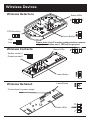
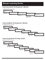
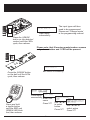
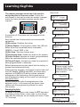
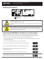
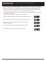
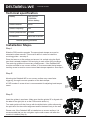
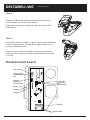
Wireless Setup Guide EN50131-3 : 2009 EN50131-6 : 2008 EN50131-5-3 : 2005 Security Grade 2 Environmental Class II RINS1348-3 Default codes: User code:1234 Master Manager Code: 2222 Engineer Code: 1111 Contents Page The Enforcer 4 Wireless Devices 5 Simple Learning Guide 6 Powering Up / Entering & Exiting Engineers 8 Learning Contacts and Detectors 9 Learning Bells 10 Learning Keyfobs 11 Deleting Inputs / Bells 12 Diagnostics13 Wireless Functions 15 Fault Displays 16 MC1-WE17 KX12DQ-WE20 KF4-WE23 SHOCK-WE25 DELTABELL-WE28 3 The Enforcer The Enforcer Control Panel 8 TUV 9 0 SPACE A B WXYZ JKL 6 MNO 3 5 DEF 2 ABC PQRS 7 GHI 4 ,/+. 1 C D BYP a = Exit manager menu b = Moves backwards to the previous menu item c = Enables chime and displays additional information in the log d = Moves forward in the log, scrolls between options/enters the master manager menu/bypasses inputs f p = Not used [ ] = Directional buttons. t = Selects items and enters menus. x = Cancels items, resets the panel and moves to next item in Master Manager menu Wireless Keyfob The keyfob may be used to set and unset the Enforcer, as well as other operations. Please see page 11 for programming. 4 Wireless Devices Wireless Detectors Status LEDs ALARM Learn Button Please note: that if learning smoke/carbon sensors only a learn button and 1 LED will be present. Enable contact 1 Disable contact 1 Learn Button Learn Button Wireless Deltabell ALARM LEARN Status LEDs Wireless Contacts LEARN High Low LEARN PIR Sensitivity Connections for power supply Status LEDs ALARM 5 Simple Learning Guide Learning Inputs (In Engineer’s Mode) Use b and x to scroll to: RADIO DEVICE CONTROL? Control Inputs? Press t Press t Learn Devices? Input 01 Available Press t Learning... [01] Enter Input. Press t Learning Bells (In Engineer’s Mode) Use b and x to scroll to: RADIO DEVICE CONTROL? Control Inputs? Press t Control Bells? Press x Learn Devices? Press t Input 01 Available Press t [01] Learning... Enter Input. Press t Learning Keyfobs (In Day mode) Use b and x to scroll to: Enforcer Time 8:30am c Enter Your Code [*****] Press D SET DATE & TIME? Enter Master Manager Code CHANGE CODES? Press x Press t Change User Codes? User Number [02] Press t Select User Press t 6 Enter user code [ ] LEARN The input types will then need to be programmed. Please see ‘Change Inputs’ in the programming manual. Input Learnt Press the ‘LEARN’ button on the detector/ contact until the LEDs cycle, then release. Input learnt successfully LEARN Please note: that if learning smoke/carbon sensors only a learn button and 1 LED will be present. Bell Learnt Bell learnt successfully Press the ‘LEARN’ button on the bell until the LEDs cycle, then release. Enter user code [******] User Name Code learnt _ successfully Press and hold a keyfob button until the RED and GREEN LED flash fast, then release. Enter user name Press t 7 Select Button Lock [1] Button Action[2] Use [] Set Area to select button. Press t Use [] to select action Press t Powering Up / Entering & Exiting Engineers Please note that the initial power up may take a few minutes. Once the time is displayed, programming can begin. Please Wait... Enforcer Time 03:21c Day Mode Entering the Engineer Menu Enforcer Time Exiting the Engineer Menu SOFTWARE REVISION? 03:21c Enter the engineer’s code Use b and x to scroll to: Enter Your Code [**** ] EXIT ENGINEER MENU? Press t Enforcer Time Active Faults Battery Fault100 03:21c Day Mode Any faults are shown. Press x SET/UNSET SYSTEM? OR Press x SOFTWARE REVISION? SOFTWARE REVISION? Engineer’s Menu Press a* Enforcer Time 03:21c Day Mode *Note: You can only exit engineer’s mode if a main menu is showing (capital letters) 8 Learning Contacts & Detectors 6 8 TUV 9 0 SPACE A B WXYZ 3 5 MNO PQRS 2 DEF GHI 7 JKL 4 ABC 1 ,/+. It is recommended that all detectors, door contacts or Use b and x to scroll to: smoke detectors are learnt at the Enforcer before any RADIO DEVICE installation/mounting is done. This makes learning CONTROL? much quicker. C D BYP Press t Control Inputs? TUV 0 3 6 9 A B WXYZ 8 MNO PQRS 5 SPACE DEF GHI 2 JKL 7 ABC 4 ,/+. 1 Press t C D BYP Learn Devices? A maximum of 32 wireless inputs may be learnt. Even though the ‘learn’ may be successful, the position of the input in a property must be tested for signal strength before it is actually ‘fixed’ into place. Please see page 13 when analysing the wireless range and signal strength. Before learning each input (detector or door contact) check that the battery is present and inserted correctly. Follow the instructions on the right to start learning the inputs. An input that is learnt correctly will flash the GREEN LED briefly and ‘Input Learnt’ will be displayed on the keypad. Both of these instances need to occur to indicate a successful learn. Red Blue Green Once learning has completed, each input needs to be given a type (final exit, intruder,etc.) please see the main programming manual (Change Inputs) for more information. Press t Input 01 Available [01] Input 02 Learnt [02] Enter Input. Press t If ‘learnt’ is displayed on an input, this will need to be deleted before learning can begin. See page 12 for deleting inputs. Learning... When ‘Learning’ is displayed, press and hold the ‘LEARN’ button on the device until the LEDs cycle, then release. Input Learnt Input Learnt Already! If the input device has already been learnt to the Enforcer system, ‘Input Learnt Already!’ will be displayed. Press t 9 Learning Bells It is recommended that all wireless bells are learnt at the Enforcer before any installation/mounting is done. This makes learning much quicker. Use b and x to scroll to: RADIO DEVICE CONTROL? Press t Control Inputs? TUV 0 SPACE 3 6 9 A B WXYZ PQRS 8 MNO 5 JKL GHI 2 DEF 7 ABC 4 ,/+. 1 C D Press x BYP Control Bells? A maximum of 2 wireless external bells (Deltabell WE) can be connected to the Enforcer. Even though the ‘learn’ may be successful, the position of the bell box on a property must be tested for signal strength before it is actually ‘fixed’ into place. Please see page 13 when analysing the wireless range and signal strength. Before learning each bell check that the battery is present and is inserted correctly. Follow the instructions to the right to start learning the bells. A bell that is learnt correctly will flash the GREEN LED briefly and display ‘Bell Learnt’ on the keypad. Both of these instances need to occur to indicate a successful learn. Press t Learn Devices? Press t Select Bell Available [1] Select Bell Learnt [2] Enter Bell. Press t If ‘learnt’ is displayed on a bell, this will need to be deleted before learning can begin. See page 12 for deleting bells. Learning... When ‘Learning’ is displayed, press and hold the ‘LEARN’ button on the bell until the LEDs cycle, then release. Green Blue Red Bell Learnt Bell Learnt Already! If the bell device is already learnt on the Enforcer system, ‘Bell Learnt Already!’ will be displayed. Press t 10 Learning Keyfobs The master manager menu has to be used to assign keyfobs to the user codes. Follow the instructions to the right to enter the master manager menu (for more information please see the user manual). Day mode Enforcer Time 8:30am c Press d Enter Your Code [*****] TUV 9 0 SPACE A B WXYZ 6 8 MNO PQRS 3 5 DEF GHI 2 JKL 7 ABC 4 ,/+. 1 Enter master manager code C D BYP SET DATE & TIME? A maximum of 32 keyfobs can be assigned to the Enforcer. Each keyfob has 4 buttons that can have specific operations: [0] No action: Disables the button [1] Show Status: If the keyfob is learnt, the LED will flicker when the nominated button is pressed. GREEN = Unset. RED = Set. [2] Set Area: Sets the chosen area [3] Unset Any Area: Unsets any area on the system [4] Latch Output: Latches an output (programmable) when the nominated button is pressed. [5] Timed Output: Activates an output for a period of time (programmable in seconds) Before learning each keyfob check that the battery is present and inserted correctly. When learning a keyfob, any button must be held until the LED flashes GREEN and RED, and then when released, a GREEN LED will be shown, asterisks will appear in the brackets on the keypad and an acknowledgement beep will be heard, all indicating a successful learn. Keyfob buttons can also be programmed in the engineer menu, in the same way as shown here (please see the programming manual for more information) Deleting Keyfobs To delete a keyfob/user code, press the c key when the display shows ‘Enter a user code’ on the chosen code and the astericks on the display will erase. Press t to accept Press x CHANGE CODES? Press t Change User Codes? Press t User Number [02] Select User, Press t Enter user code [ ] Press and hold any button on the keyfob until the RED and GREEN LEDs flash, then release. Enter user code [******] Asterisks will appear, Press t User Name _ Enter Name. Press t Select Button Lock [1] Use [].Press t Button Action[2] Set Area Use [] Press t# 11 Deleting Inputs / Bells Deleting inputs and bells from the Enforcer can either be done collectively or individually. Deleting Inputs Deleting Bells Use b and x to scroll to: Use b and x to scroll to: RADIO DEVICE CONTROL? RADIO DEVICE CONTROL? Press t Press t Control Inputs? Control Inputs? Press t Press x Learn Devices? Control Bells? Press x Press t Learn Devices? Delete Devices? Press x Press t Delete Devices? Delete All? Press t Press x to delete individually Press t Input 01 Learnt Delete All? [01] Press x to delete individually Use [ ] Press t Press t Enter your code [ ] Select Bell Learnt [01] Use [ ] Press t Enter 2000 Enter your code [ ] Inputs Deleted Enter 2000 Input(s) deleted Bells Deleted Bells deleted 12 Diagnostics The diagnostics function shows all wireless (radio) input and bell signal strengths and battery strengths. Signal Strength (Inputs and Bells) One of the most important factors for a reliable wireless installation is the signal strength between a wireless device and the panel. If a device is out of range it will not be able to send events to the Enforcer panel therefore it is recommended that a signal strength test is performed before fixing devices into place. The Enforcer has an advanced signal strength mechanism that operates by monitoring all inputs/bells after 5 minutes from the start of the test. It will perform this test every 16 seconds. NOTE: When performing a signal strength test it is recommended that the system is tested in the ‘worst case scenario’ for example with all doors and windows closed. Once the function is entered, a count down from 300 will begin, when 0 is reached the input results display will be shown, or press t during the count down to go to the input display immediately, one of the following will be displayed: Result Action - No device installed ? Waiting for device signal strength information 0 Missing (reposition and retest) 1 Weak signal (reposition and retest) 2 Good install position 3 Excellent signal Action Excellent [50 to 100] OK to install Good [30 to 49] OK to install Weak [0-29] Not OK to install Missing [-] Not OK to install DIAGNOSTICS? Press t View PSUs? Press x View Inputs? Press x View Radio Device Status? Press t Signal Strength? Press t Inputs? Press t Please Wait 299 Press t 3-------------------------------- Press t The signal strength can also be read from the wireless device LEDs. GREEN LED = Good. RED LED = Bad When the display is showing the input status, pressing t will show each individual input and a detailed signal strength reading will be shown as follows: Result Use b and x to scroll to: Input Excellent [01] [100] Use [ ] Press t Bells? Press t ?- Press t 13 Diagnostics Diagnostics Continued... Battery Status The diagnostics function also monitors the battery of each of input and bell so that any low/bad batteries can be quickly recognised and replaced. The Enforcer has an advanced battery test mechanism that operates by monitoring all inputs/bells after 5 minutes from the start of the test. It will perform this test every 16 seconds. Once the function is entered, a count down from 300 will begin. Press t to go to the main display, one of the following will be displayed: Testing Waiting for a battery result Good At least one month of battery life remaining Replace Battery needs to be replaced immediately Bell No Signal [1] [000] Press t Battery? Press t Inputs? Press t Please Wait 300 Press t Input Good [01] Use [ ] Press t Bells? Press t Bell Good [1] Press t Input Excellent [01] [100] Use [ ] Press t 14 Wireless Functions Site Options Use b and x to scroll to: In the site options function there are 3 functions for the Enforcer: • Radio Force Set: If any radio device is in fault (e.g. has failed supervision or the signal is jammed) and if this option is enabled, the user can force the Enforcer to set regardless. [0] No [1] Yes • Set With Polling Fault: This allows the Enforcer to set even if a device has missed 20 minutes worth of device polls. [0] No [1] Yes • Fob Unset Entry: If this function is enabled a keyfob can only be used to unset the control panel when the entry time is counting down. [0] No [1] Yes • Radio Bell Supervision: If this function is enabled, the bell performs its own supervision and jamming protection, and will alarm if either condition occurs (this cannot be silenced by the panel). The alarm will stop after the bell expiry time, when the jamming stops or when a supervision message has been received by the panel. If this function is disabled, it will work the same way as an input. No supervision or jamming will be detected by the bell, but the Enforcer will still detect both depending on the timers. SITE OPTIONS? Press t until: Radio Force Set No [0] Use [ ], t until Set with Poll Fl No [0] Use [ ], t until Fob Unset Entry No [0] Use [ ], t until Radio Bell Sprvn No [0] Press t [0] No [1] Yes Use b and x to scroll to: Change Timers In the change timers function there are 2 functions for the wireless (radio) operation: • Radio Supervision Time: This is the time window before a supervision fault will be signalled. For example: if the time is set for 2 hours, then any device that doesn’t communicate with the Enforcer within that period will cause a supervision fault. [0- 99] hours (0=supervision faults ignored) NOTE: Must be set to 2 hours or less to comply with EN50131. • Radio Jamming Time: This is the time window that monitors the signals of each wireless device. If a signal is ‘blocked’ for longer that the programmed time a fault will be displayed. [0- 100] seconds (0=jamming faults ignored). NOTE: It is not recommended to program less than 10 seconds. Must be set to 100 seconds or less (but not to zero) to comply with EN50131. 15 CHANGE TIMERS? Press t until: Radio Sprvn Time [02] Use [ ], t until Radio Jmmng Time [030] Press t Fault Displays Radio Mismatch: If an input is assigned as a type (final exit, intruder, etc) but a detector has not been learnt on this input number or a detector has been learnt but not assigned an input type, this fault will be displayed. Radio mismatch Input 01 Radio Tamper: If a radio input is in tamper, the alarm will activate and the input in fault will be displayed. Alarm Silenced Input Battery Low: The Enforcer monitors the batteries of each wireless device and is defined by the following: Battery Low UXX (U = Keyfobs. XX = User Number) User Battery Low U05 Battery Low IXX (I = Inputs. XX = Input Number) Battery Low BXX (B = Bell. XX = Bell Number) If battery low is displayed it is advisable to replace the battery within 28 days of this message being shown. Radio Supervision: The Enforcer monitors the operation of each wireless device and is defined by the following: Radio Supervision IXX (I = Input, XX = Input Number) Radio Supervision BXX (B = Bell, XX = Bell Number) Input 02 Superv Fault I02 If this occurs it would be advisable to check the signal strength of the device in the diagnostics function. Jamming: This is reported when a jamming signal is recognised on the radio frequency. Check that no radio interference is in close proximity to the radio devices/panel. Radio Poll Fault: This is displayed when no ‘polls’ are received for 20 minutes before the set operation Test the signal strength / battery on each wireless device. Unable to set Jamming 700 Unable to set Radio poll F700 PLEASE NOTE THAT SETTING MAY NOT BE POSSIBLE IF ANY FAULTS ARE PRESENT ON THE CONTROL PANEL. PLEASE SEE ‘SITE OPTIONS’ IN THE MAIN PROGRAMMING MANUAL TO ALTER THIS SETTING 16 + MC1-WE CR2 Battery - installed Wireless magnetic contact/universal transmitter with 1 reed, 1 input & tamper Technical Specifications Model: MC1-WE Colour: WHITE Casing: 3mm ABS, 0.4mm HDPE in Lens Area Transmission Frequency: 868MHz, FM Transceiver Narrow Band Transmission Method: Fully Encrypted Rolling Code Transmission Range: 300m Free Space Indication: Three LED Combinations (RSSI, Battery Status and Alarm) Reed Switch: 1 x MC1-WE Detection Points: 2, Side and End Detection Inputs: 1 External Input & 1 External Tamper Input Battery: 3.6V 2.2Ahr AA Lithium Battery Battery Life: Up to 2 Years Tamper Switch: Front + Optional Rear Tamper Storage Temperature: -20°C to 50°C Operating Temperature: -10°C to 50°C Rear Tamper Switch There is a rear wall tamper protection switch at the back of the MC1-WE device. This tamper protection switch prevents the device from being removed from its installed location and prevents the lid from being removed. Tamper Switch Back view of the MC1-WE Detection point The MC1-WE has a detection point: Magnet WINDOW The example below shows how you can use them on an entry door: Contact Using Magnetic Contact 1 (S1) Door Frame To enable Magnetic Contact 1 you must remove the jumper link from the S1 enable pins: Reed Switch Door Test Result S1 Z S1 Enable U T Example: T T C Z Magnetic 17 Contact 1 Enable/ Door Contact / Sensor N/C Tamper S2 Enable T Zone Learn MC1-WE Wireless magnetic contact/universal transmitter with 1 reed, 1 input & tamper Back view of the MC1-WE Tamper Switch Detection point Using Magnetic Contact 1 on a window Magnet To enable Magnetic Contact 1 you must remove the jumper link from the S1 enable pins: ng Magnetic Contact 1 (S1) Frame WINDOW Contact Reed Switch Door Test Result S1 S1 Enable Z T T C Learn Z S2 Enable Printed Circuit Board Univers Z Example: Door Contact / Sensor Status LEDs T T Tamper Enable/ Disable Zone Enable/ Disable T Magnetic Contact 1 Enable/ Disable N/C C Using Magnetic Contact 1 (S1) Door Frame Test Result S1 Z TAMPER S1 Enable Door T T C ZONE Z Z Tamper Switch Back view of the MC1-WE Learn Learn Button Test Result S1 Z Magnet WINDOW External Input & Tamper Input S1 Enable Zone Enable/ Disable T CR2 Battery T C The MC1-WE hasContact an extra input incorporated that can be used for external contacts or Learn sensors. Z RED should BLUE GREEN The jumper pins ‘Z’ and ‘T’ both be disabled when these are used. + RED CR2 Battery - TAMPER BLUE GREEN Universal Transmitter Z Example: C N/C RED T T RED ZONE T BLUE GREEN Door Contact / Sensor BLUE GREEN Z BLUE GREEN Recommended maximum cable length of 10m 18 Model: MC1-WE Colour: WHITE T C T RED If the battery neeS correct battery ty installed Z Casing: 3mm ABS, 0.4mm HDPE in Lens Area Transmission Frequency: 868MHz, FM Transceiver Narrow Band Transmission Method: Fully Encrypted Rolling Code Z C Universal Transmitter Magnet T MC1-WE T Wireless magnetic contact/universal transmitter T with 1 reed, 1 input & tamper T Door Contact / Sensor Z Example: WINDOW Contact Learn Butto N/C C Z Applying the battery S1 Z S1 C Universal Transmitter S1 Enable T Z Z Example: T T N/C Z RED BLUE G RED BLUE G RED BLUE G Reed Switch + T Door Z - CR2 Battery Test Result S1 If the battery needs to be replaced, theS1 Enable correct battery type (CR2) must Z be T installed T C CR2 Battery C Learn Z S2 Enable The batteries supplied have been chosen to provide long service life whilst, for safety RED Learn reasons, having limited output current. Z BLUE G To enable Magnetic Contact 1 you must remove Learn jumper link from the S1 enable pins: Butto Door Frame C Learn S1 Enable T Learn Z T Using TMagnetic Contact 1 (S1) Test Result Back view of the MC1-WE Z ZONE RED CR2 Battery T C S1 S1 Enable T T TAMPER Test Result Door Contact / Sensor Magnetic Contact 1 Learn Enable/ Disable Tamper Enable/ Disable Zone Z Enable/ Disable ZONE BLUE G Magnetic + WINDOW The battery is protectedIf on purchase a piece Contactbe 1 removed for Tamperthat must Zone the battery needs toby be replaced, theof plastic RED RED Enable/ Enable/ correct battery type (CR2) must beEnable/ operation. CR2 Battery Disable - installed Disable Disable BLUE G BLUE G Status LEDs Test Result S1 Z S1 Enable T Model: T Colour: C Casing: To prevent possible damage to components, any static charge on your body needsRED to be eliminated before touching the inside of the unit. This can be accomplished MC1-WE Battery some grounded/earthed metallic conductor such as a radiator/pipework byCR2 touching WHITE RED immediately before replacing the batteries. Test Result Learn Z Transmission Frequency: Transmission Method: S1 3mm ABS, 0.4mm HDPE in Lens Area Z 868MHz, FM Transceiver Narrow Band TAMPER Fully Encrypted Rolling Code Universal Transmitter ZONE the If the battery needs to be replaced, 300m Free Space S1 Enable T - + correct battery type (CR2) must be T N/C Casing: 1. Make Detection Points: T C T release the Learn button. Battery Life: through the different colours, then RED BLUE GREEN RED BLUE GREEN RED BLUE GREEN RED BLUE GREEN RED BLUE GREEN IfCR2 noBattery LED illuminates then the device is completely out of range. Reed Switch: 1 x MC1-WE Detection Points: 2, Side and End Detection Inputs: 1 External Input & 1 External Tamper Input Battery Life: If the battery needs to be replaced, the Up to 2 Years Learn The Battery: + blue LED will illuminate when the device is activated. 3.6V 2.2Ahr AA Lithium Battery CR2 Battery Tamper Switch: Storage Temperature: - correct battery type (CR2) must be installed Front + Optional Rear Tamper -20°C to 50°C 19 RED Learn Button 2, Side and End 3mm ABS, HDPEcorrectly in Lens Areaand the plastic wrapping removed. sure the battery is0.4mm installed C Transmission Range: 300m Free Space Up to 2 Years 3. The device is correctly when Green LED flashes. Tamper Switch: Front + the Optional Rear Tamper Three LEDlearnt Combinations Indication: (RSSI, Battery Status and Alarm) Storage Temperature: -20°C to 50°C Reed Switch: 1 x MC1-WE Operating Temperature: -10°C toindication 50°C The three coloured LEDs give a visual of the signal strength. Detection Points: 2, Side and End Model: MC1-WE Detection Inputs: 1 External Input & 1 External Tamper Input Colour: WHITE Battery: 3.6Vsignal 2.2Ahr AA Lithium Battery Green indicates good strength and is a good location to install. Casing: 3mm ABS, 0.4mm HDPE in Lens Area Battery Life: Up to 2 Years Transmission Frequency: 868MHz, FM Transceiver Narrow Band Tamper Switch: Front + Optional Rear Tamper Red indicates poor Fully signal strength and the device should not be Transmission Method: Encrypted Rolling Code Storage Temperature: -20°C to 50°C Test Result S1installed Enable in that position. Transmission Range: 300m Free Space Operating Temperature: -10°C to 50°C Three LED Combinations Indication: (RSSI, Battery Status and Alarm) S1 Learn Z receiving equipment, and when the Manual) follow the procedure below. Detection Inputs: 1 External Input & 1 External Tamper Input Transmission Frequency: 868MHz, FM Transceiver Narrow Band 2. Press and Hold the Learn button until the 3 LEDs start cycling 3.6VCode 2.2Ahr AA Lithium Battery Transmission Method:Battery: Fully EncryptedZ Rolling BLUE G T Learning the MC1-WE to the Enforcer control panel Transmission Range: Example: CR2 Battery Z ThreeT LED Combinations installed Indication: When you are ready to learn the device to the control panel (RSSI, Battery Status and Alarm) Model: MC1-WE equipment is in the learn mode (see Enforcer Programming Reed Switch: 1 x MC1-WE Colour: WHITE T BLUE G BLUE G CASE LID SCREW FITTING Alarm mponents, eds to be ide of the touching onductor ediately KX12DQ-WE Wall CR123A LITHIUM BATTERY 2m - 1m 1m 12m Wireless PIR Detector - Model: KX12DW Colour: WHITE Casing: 3mmABS, 0.4mm HDPE in LensArea Transmission Frequency: 868MHz, FMTransceiver Narrow Band Tranmission Method: Fully Encrypted Rolling Code Transmission Range: 300m Free Space Detection Method: Low Noise Pyroelectric Sensor Sensitivity: High, Low 1m 12m Detection Zones: 74 Detection Speed: Piro Sensor 0.3 - 3.0 m/s DetectionAngle: 85 Battery: CR123A Lithium Battery Battery Life: Greater than 2 years Mounting Height: 1.8m to 2.4m Tamper Switch: Front + Optional RearTamper Storage Temperature: -20 C to 50 C Operating Temperature: -10 C to 50 C REAR TAMPER 69mm (2.72”) Emissions: Immunity: 4m 5m 6m 7m 12m 11m 9m 7m Coverage pattern NVM RESET 6M 5m + Vertical coverage 3m 2m -85 74 zones O 1m 7 planes 1m 12m 2m 3m 4m 5m 6m 7m 8m 9m 10m11m 12m 11m 2.4m 10m 9m 8m 1m 7m 6M KX12DW ® 5m 2m 3m 4m 5m 6m 7m 8m 9m 10m11m 12m 12m Internal detector WHITE 4m 3mmABS, 0.4mm HDPE in LensArea 3m on Frequency: 868MHz, FMTransceiver Narrow Band 2m n Method: Fully Encrypted Rolling Code on Range: 300m Free Space Method: 4m Horizontal coverage CR123A LITHIUM BATTERY 1m 1m 2m 3m 4m 5m 6m Low Noise Pyroelectric Sensor High, Low re Compensation: AdvancedAutomatic 2.4m 7m 8m 9m 10m1 RED BLUE GREEN RED BLUE GREEN 10m11m 12m 20 RED B RED B RED B RED B RED B = 105g (3.4 oz) without bracket 10m = 105gEN50130-4 (3.4 oz) without bracket Alarm 10 50mm (2.2”) 8m CR123A LITHIUM BATTERY 8m 9m 8m 9m 85O 74 zones 7 planes EN55022 Class B Kg 2m 3m 117mm (4.61”) 69mm Wall and ceiling50mm mounting brackets optional (2.72”) (2.2”) Accessories: 7m 117mm (4.61”) Kg Detection Range: (0.12") 5m 6m 3mm (0.12") 12m Internal detector Temperature Compensation: Learn AdvancedAutomatic Button DO NOT TOUCH 3mm 4m 2.4m Header for Rear Tamper Technical Specifications ® 2m 3m Part number: FPKXBRACKET Ceiling umber: FPKXBRACKET + + KX12DQ-WE 12m Wireless PIR Detector Wall Ceiling Installation & wall mounting ng the it is . NOTE: When mounting the detector, ensure that it is not tilting backwards. CASE LID SCREW FITTING Part number: FPKXBRACKET OptionalHeader bracket fitting for Rear Tamper Wall Ceiling 3mm (0.12") + Battery - 117mm (4.61”) Tamper Spring NOTE: When mounting the detector, ensure that it is not tilting backwards. + 69mm (2.72”) ING Learn Button Kg CASE LID 50mm (2.2”) = 105gSCREW (3.4 oz) without bracket FITTING DIGITAL SIGNAL PROCESSING SELECT Part number: FPKXBRACKET Piro Sensor DO NOT TOUCH SENSITIVITY Part nu Header On = HIGH) The KX12DW-WE Printed Circuit Board r 3mm (0.12") Header for Rear Tamper Sensitivity Settings Header Off = LOW Battery Tamper Spring REAR TAMPER 85O 74 zones 7 planes - 11m 10m 9m SENSITIVITY NVM RESET + - 69mm (2.72”) Kg Header On = HIGH) Alarm Header Off = LOW 50mm (2.2”) REAR TAMPER 8m 7m = 105g (3.4 oz) without bracket 6M 5m The batteries supplied have been chosen to Learn Button provide long service life whilst, for safety 4m reasons, having limited output current. 3m + CR123A LITHIUM BATTERY Piro DO N 117mm 12m (4.61”) + CR123A LITHIUM DIGITAL SIGNAL BATTERY PROCESSING SELECT - Replace only with approved batteries. 2m - Piro Sensor 1m DO NOT 2m TOUCH 3m 4m 1m Sensitivity Settings 5m 6m 7m + 8m 9m CR123A LITHIUM BATTERY - 10m11m 12m Alarm 21To prevent 85 possible damage to components, O zones any 74 static charge on your body needs to be - KX12DQ-WE 12m Wireless PIR Detector DIGITAL SIGNAL PROCESSING SELECT Learn Button Avoiding false alarms SENSITIVITY Header On = HIGH) 1. Avoid placing the detector in direct sunlight. Piro Sensor system is armed. 2. Do not let pets and other animals wander freely whilst the alarm Off 3. DoHeader the detector near heaters or radiators. DO NOT TOUCH =not LOWmountSensitivity Settings 4. Do not mount the detector near open windows or air vents. 5. Mount the detector on a stable surface. Using Magnetic Contact 1 (S1) To enable Magnetic Contact 1 you must remove jumper link from the S1 enable pins: Door Frame Changing the battery Reed Switch Door Test Result REAR TAMPER S1 S1 Enable Z Back view of the MC1-WE T T C Learn + Replace only with approved batteries. CR123A LITHIUM BATTERY - WINDOW NVM RESET Z The batteries supplied have been chosen to provide long service life whilst, for safety reasons, having limited output current. Magnetic Contact 1 Enable/ Disable Tamper Enable/ Disable Zone Enable/ Disable Alarm Status LEDs CR123A LITHIUM BATTERY + To prevent possible damage to components, any static charge on your body needs to be eliminated before touching the inside of the unit. This can be accomplished by touching some grounded/earthed metallic conductor such as a radiator/pipework immediately S2 Enable Test Result S1 Z TAMPER Universal Transmitter S1 Enable T T C Learning the MC1-WE Z T to the Enforcer control panel Example: ZONE Learn Z T T When you are ready to learn the device to the control panel receiving equipment, and when the T (see Enforcer Programming Manual) follow equipment is in the learn mode the procedure below. ® Model: KX12DW 12m Internal detector Learn Button N/C Colour: WHITE removed. C 1. Make sure the battery is installed correctly and the plastic wrapping Casing: 3mmABS, 0.4mm HDPE in LensArea Tranmission Method: Fully Encrypted Rolling Code Transmission Range: 300m Free Space 2. Press and Hold the Learn button until the 3 LEDs start cycling through the different colours, then Z Transmission Frequency: 868MHz, FMTransceiver Narrow Band release the Learn button. 3. The device is correctly learnt when the Green LED flashes. Detectionof Method: Low Noise Pyroelectric Sensor The three coloured LEDs give a visual indication the signal strength. Sensitivity: High, Low RED BLUE GREEN RED BLUE GREEN RED BLUE GREEN RED BLUE GREEN Temperature Compensation: AdvancedAutomatic Green indicates good signal strength and isDetection a good location to install. Range: 12m Detection Zones: Red indicates poor signal strength and the Detection device Speed: should not be DetectionAngle: in that position. S1installed Enable Test Result S1 Battery: T Battery Life: IfCR2 noBattery LED illuminates then the device is completely out of range. Learn + - 0.3 - 3.0 m/s 85 CR123A Lithium Battery Greater than 2 years Mounting Height: 1.8m to 2.4m Tamper Switch: Front + Optional RearTamper Storage Temperature: -20 C to 50 C The blue LED will illuminate when the device is activated. Operating Temperature: CR2 Battery 74 If the battery needs to be replaced, the Accessories: correct battery type (CR2) must be installed Emissions: 22 Immunity: -10 C to 50 C RED BLUE GREEN Wall and ceiling mounting brackets optional EN55022 Class B EN50130-4 KF4-WE 4 Button, two way Specifications Transmission Frequency: 868MHz Transmission Method: Fully encrypted rolling code Transmission Range: 300m free space Battery: CR-1/3N Li-Mn Cell (3 volts) Battery Life: Up to 2 years Operating Temperature: -10 to +40 °C Emissions: EN55022 Class B Immunity: EN50130-4 Dimensions: 60 x 40 x 15 mm Weight: 28g KF4-WE Learning Transmission Frequency: 1. Put the Enforcer control panel into868MHz the “Change Codes” menu Transmission Method: Fully encrypted rolling code Transmission Range: 300m free space Battery: CR-1/3N Li-Mn Cell (3 volts) (see Enforcer User Manual for full details). 2. When prompted to enter a new user code, press any keyfob button. 3. Once asterisks appear on the Enforcer keypad, the new keyfob is learned on the system. Battery Life: Up to 2 years Operating Temperature: -10 to +40 °C EN55022 Class B LockKeyfob Button LockingEmissions: the Immunity: EN50130-4 Weight: 28g LED presses won’t affect your alarm All 4 buttons on the keyfob may be locked so that anyStatus accidental Dimensions: 60 x 40 x 15 mm I Button system. Locking the keys on the keyfob is performed by pressing any buttons that are diagonal with one another at the same time: i.e. Lock & II or Unlock & I. The RED LED will flash indicating that the fob has been locked. Unlock Button To unlock, press both buttons together again, and the GREEN LED will flash indicating that the keyfob is now unlocked. Note: When locked, the LED status is disabled. II Button The KF4-WE Buttons Lock Button Status LED I Button The batteries supplied have been chosen to provide long service life whilst, for safety reasons, having limited output current. Unlock Button Replace only with approved batteries. II Button - (Negative) To prevent possible damage to components, any static charge on your body needs to be eliminated before touching the inside of the 23 + (Positive) KF4-WE 4 Button, two way II Button Changing The Battery The batteries supplied have been chosen to provide long service life whilst, for safety reasons, having limited output current. Replace only with approved batteries. - (Negative) To prevent possible damage to components, any static charge on your body needs to be eliminated before touching the inside of the unit. This can be accomplished by touching some grounded/earthed metallic conductor such as a radiator/pipework immediately + (Positive) CR-1/3N Li-Mn Cell (3 volts) Resetting the keyfob To do a nvm reset on the keyfob, first remove the battery, then press and hold down the lock and unlock buttons together and reinsert the battery at the same time. Continue holding down the buttons for another 10 seconds and then release. 24 Battery SHOCK-WE + LEDs Technical specification Rear Tamper Sensitivity Voltage: >2.5V High range sensitivity band Specification Current:Electrical 12uA Voltage: >2.5V Sensitivity Low range sensitivity band High band Disturbance: range Rollingsensitivity 30s period Battery Current: 12uA Low range sensitivity band Life: Greater than 2 years Disturbance: Rolling 30s period Operating Environment CR2 3.0Battery Volt -10 to 50°C Life: Greater than 2 years Operating Environment CR2 3.0 Volt -10 to 50°C Disabled Front Tamper Electrical Specification Enabled Disabled The function of the shock sensor wireless transmitter is to provide an alarm signal if vibrations picked Learn Button up from its mounting surface exceed a predetermined level, which can be easily adjusted. Enabled The wireless transmitter with wall tamper and shock sensor is used on the Enforcer Radio Control Panel along with the current range of detectors, receivers and transmitters. Enabled Disabled Wireless transmitter with wall tamper and shock sensor Printed Circuit Board High Range Sensitivity Band: Link Off and Turn Battery potentiometer right for - LEDs more sensitive and left + sensitive for less Battery LEDs Disabled + Learn Button Front Tamper Learn Button Front Tamper Rear Tamper Low/High Sensitivity Pulse Count 4 Sensitivity Band Pulse Count 2 Low Range Sensitivity Band: + CR2 BATTERY - Enabled Tamper Adjustable PCBRear settings LED Enable Background Disturbance Disabled - Link On and Turn potentiometer right for more sensitive left for less sensitive Disabled w Range Sensitivity Band: High Range Sensitivity Band: Link Off and Turn right for Low Rangepotentiometer Sensitivity Band: LEARN more sensitive and left Off and Turn for lessLink sensitive potentiometer right for more sensitive and left 25 for less sensitive Link On and Turn potentiometer right for High Range Sensitivity Band: more sensitive left for Link On and Turn less sensitive potentiometer right for more sensitive left for less sensitive Sensitivity High range sensitivity band SHOCK-WE Wireless band transmitter with wall tamper and shock sensor Low range sensitivity Disturbance: Rolling 30s period Sensitivity High range sensitivity band Descriptions Operating Environment Electrical Specification Sensitivity range band a vibration, 1. Tri-Colour LED:Low When thesensitivity sensor detects the LED will illuminate in one of two colours: -10 to 50°C Rolling 30s period High range sensitivity band Disturbance: Voltage: >2.5V Current: 12uA Pre-Alarm Detection, but the alarm threshold Low range band GREEN: notsensitivity yet reached BLUE: Alarm Operating Environment Disturbance: Rolling 30s period -10 to 50°C Battery Life: 2 years LED illuminates, the sensitivity Operating Environment of the unit may need increasing. Please see “7. Greater If only than the GREEN 3.0 Potentiometer and Sensitivity Range” to increase sensitivity. CR2 Volt -10the to 50°C Enabled 2. Background Disturbance: If there is a constant background disturbance then this can be filtered out by fitting the background disturbance link which will monitor for this. Disabled LEDs Learn Button 4. Reset Button: Front Tamper Rear Tamper 5. Pulse 4: If this link is fitted, a count of 4 pulses (GREEN LED) in a rolling 30 second window, will generate an alarm activation. Disabled Enabled Front Tamper Enabled Rear Tamper Enabled Disabled To learn the wireless transmitter on the radio expander, the reset button needs to be pressed after the battery is installed. For full programming on this procedure, please refer to the expander manual. Learn Button 6. Pulse 2: If this link is fitted, a count of 2 pulses (GREEN LED) tivity Band: Range Sensitivity Band: in a rolling 30 secondHigh window, will generate an alarm activation. Link Off and Turn Link On and Turn potentiometer right for potentiometer right for more sensitive and left and Sensitivity Range: Themore sensitive forincreased or decreased using 7. Potentiometer sensitivity can beleft either vity Band: High Range Sensitivity or less sensitive lessBand: sensitive the potentiometer and sensitivity link. nk Off and Turn Link On and Turn otentiometer right for potentiometer right Sensitivity for Low Range Sensitivity Band: High Range Band: ore sensitive and left more sensitive left for Link Off and Turn Link On and Turn r less sensitive less sensitive potentiometer right for potentiometer right for more sensitive and left more sensitive left for for less sensitive less sensitive Low/High Sensitivity Sensitivity Band Pulse Count 2 Pulse Count 4 LED Enable Background 26 Disabled Enabled Enabled Enabled Disabled Rear Tamper Disabled Disabled Disabled Battery Enable: is removed, the tri-colour LED will be 3. LED Learn Button If this- linkLEDs Front Tamper at all times, which will save battery life. disabled + Disabled Enabled LEDs Disabled - SHOCK-WE Test Result S1 S1 Enable Wireless transmitter with wall tamper and shock sensor Z T TAMPER T C Universal Transmitter Learning the SHOCKWE to the Enforcer control panel Z T Example: ZONE Learn Z T T When you are ready to learn the device to the control panel receiving equipment, and when the T (see Enforcer Programming Manual) follow the procedure below. equipment is in the learn mode Learn Button N/C C 1. Make sure the battery is installed correctly and the plastic wrapping removed. 2. Press and Hold the Learn button until the 3 LEDs start cycling through the different colours, then Z release the Learn button. 3. The device is correctly learnt when the Green LED flashes. The three coloured LEDs give a visual indication of the signal strength. RED BLUE GREEN RED BLUE GREEN RED BLUE GREEN RED BLUE GREEN RED BLUE GREEN Green indicates good signal strength and is a good location to install. Red indicates poor signal strength and the device should not be in that position. S1installed Enable Test Result S1 cy: e: T IfCR2 noBattery LED illuminates then the device is completely out of range. Learn The blue LED will illuminate when the device is activated. + CR2 Battery - If the battery needs to be replaced, the correct battery type (CR2) must be installed MC1-WE WHITE 3mm ABS, 0.4mm HDPE in Lens Area 868MHz, FM Transceiver Narrow Band Fully Encrypted Rolling Code 300m Free Space Three LED Combinations (RSSI, Battery Status and Alarm) 1 x MC1-WE 2, Side and End 1 External Input & 1 External Tamper Input 3.6V 2.2Ahr AA Lithium Battery Up to 2 Years Front + Optional Rear Tamper -20°C to 50°C -10°C to 50°C 27 DELTABELL-WE External sounder Technical specification Battery CR3 3.0 volt 11000MAh Lithium battery Strobe duration 10mS Strobe Frequency 1Hz Sound pressure level 101dBA Dimensions 290 x 285 x 50 mm Reverse polarity protected Installation Steps: Step 1 Slide the PCB module upwards. The sprung back-tamper arm can be retracted to allow removal. This must be done in order to install the revolving guides - see step 3. Place the base on a flat surface and ensure it is vertical using the Spirit level that is already installed. Drill and plug in each of the fixing locations. The revolving guides will correct any misalignment. If the Deltabell WE must be mounted on an uneven surface, it is recommended that a tamper levelling screw is used to ensure correct back-tamper operation. See step 2. Step 2 Mounting the Deltabell WE on an uneven surface may cause false triggering, through incorrect operation of the back-tamper. A POZI number 2 screw driver is recommended for adjusting back tamper screw. Step 3 Insert the guides in as shown. Make sure that the guides ‘B’ is aligned with the tabs to the right (this is so the PCB module slides in) Turn each guide until they line up with the drilled holes, while referencing the spirit level for the correct alignment and fix the base firmly to the wall. Tamper Please note, if the Deltabell WE is installed onlevelling an uneven surface, it is screw recommended that you do not tighten up the wall screws until after the module is installed (step 4). 28 Tamper levelling screw DELTABELL-WE Tampe levellin screw External sounder Step 4 Place the PCB module, ensuring that the arrow is aligned with the marker (on the left of the module). Expose the terminals by releasing the latch on the top of the PCB module. Tamper levelling screw Step 5 Fit the lid by sliding its hinges into place. The lid can be supported in the fully open position; to close the lid, apply a little force to push the lid past the holds. Lea Com Ena link Close the cover, ensure the tamper is operating correctly and insert the 25mm long screw supplied and rotate the screw cover to a close. Opt aux volt Bat Printed circuit board Sou Tam Learn button LEARN Comfort LED Enable/Disable link AC/DC + BAT Red LED Blue LED Green LED - BATTERY LED3 LED2 LED1 Optional auxillary 12 volt PSU input SOUNDER Battery TAMPER Sounder The batteries supplied have been chosen to provide long service life whilst, for safety reasons, having limited output current. Tamper Replace only with approved batteries. Strobe To prevent possible damage to Comfort The batteries supplied have been chosen to provide long service life whilst, for safety reasons, having 29 limited output current. components, any static charge on your Battery before body needs to be eliminated touching the inside of the unit. This can be accomplished by touching some grounded/earthed metallic conductor LEDssuch as a radiator/pipework immediately before replacing batteries. Tamper sw DELTABELL-WE External sounder Battery Using Magnetic Contact 1 (S1) Door Frame To enable Magnetic Contact 1 you must remove jumper link from the S1 enable pins: Battery Reed Switch Door Test Result S1 The batteries supplied have been S1 Enable Z Back view of thechosen MC1-WE to provide long service life B T T whilst, for safety reasons, having limited output current. C Learn Z S2 Enable S Replace only with approved batteries. S Tamper Enable/ Disable Zone Enable/ Disable WINDOW To prevent possible damage to components, any static charge on your body needs to be eliminated before touching the inside of the unit. This can be accomplished by touching some grounded/earthed metallic conductor such as a radiator/pipework immediately before replacing batteries. Magnetic Contact 1 Enable/ Disable Test Result Tamper switch S1 Z TAMPER S1 Enable T T C Learning the DELTABELL-WE to the Enforcer Z T Example: Universal Transmitter ZONE Z Learn T T When you are ready to learn the device to the control panel, and when the Enforcer is in the learn T mode (see Enforcer Programming Manual) follow the procedure below. Learn Button N/C C correctly and the plastic wrapping removed. 1. Make sure the battery is installed 2. Press and Hold the Learn button until the 3 LEDs start cycling through the different colours, then Z release the Learn button. 3. The device is correctly learnt when the Green LED flashes. The three coloured LEDs give a visual indication of the signal strength. RED BLUE GREEN RED BLUE GREEN RED BLUE GREEN RED BLUE GREEN RED BLUE GREEN Green indicates good signal strength and is a good location to install. Red indicates poor signal strength and the device should not be in that position. S1installed Enable Test Result S1 T IfCR2 noBattery LED illuminates then the device is completely out of range. Learn The blue LED will illuminate when the device is activated. + S Status LEDs CR2 Battery - If the battery needs to be replaced, the correct battery type (CR2) must be installed 30 D 31 Customer support: Customer support line (UK only): +44(0)845 6434 999 (local rate) Or telephone: +44(0)1709 535225 Hours: Mon to Fri, 8:00am till 6:30pm Email: [email protected] Website: www.pyronix.com Email: [email protected] Website: www.castle-caretech.com