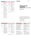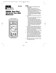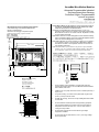
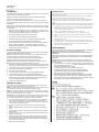
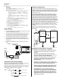
1
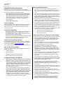
VersaMax MicroMotion Modules
Automate Programmable Industriel
Speicherprogrammierbare Steuerung
Controllore Logico Programmabile
Automata Programable
_________________________________________________________________________________________________________________________
The MicroMotion Module can be mounted on a wall or panel using screws, or
on a DIN rail. The MicroMotion Module must be mounted on a vertical
surface. Do not mount it on a horizontal surface.
Mounting Dimensions and Spacing Requirements
Cotes de Montage et Contraintes d'Espacement
Montage- und Abstandsmaße
Dimensioni di montaggio e requisiti di spazio
Dimensiones de montaje y espacio necesario
50 mm
(1.97 in)
L’automate programmable Micro peut être vissé sur un mur ou un
panneau, ou bien monté sur un rail DIN. L’automate programmable
Micro doit être monté sur une surface verticale. Ne jamais le monter
sur une surface horizontale.
Die MicroMotion Module kann auf einer Montageplatte oder einer DIN-Schiene befestigt
werden. Die MicroMotion Module muß auf einer vertikalen Montagefläche installiert
werden. Eine horizontale Montagefläche ist nicht zulässig.
Il MicroMotion Module può essere montato con delle viti su una parete o
su un pannello, oppure su una guida DIN. Il MicroMotion Module
deve essere montato su una superficie verticale. Non montarlo su
una superficie orizzontale.
El MicroMotion Module se puede montar en una pared o un panel, utilizando
tornillos, o bien, en un riel DIN. El MicroMotion Module se debe montar
en una superficie vertical. No se monte en una superficie horizontal.
150mm (6.00 in)
140mm (5.60 in)
EXP.
EXP.
MEMORY
PACK
90mm
(3.60 in)
80mm
(3.20 in)
50 mm
(1.97 in)
Yes
Oui
Ja
Sì
Sí
10 mm
(0.39 in)
4.8mm
(0.20in)
Minimum allowance for cooling
Dégagement d'aération
Minimalabstände zur Kühlung
Spazio per il raffreddamento
Margen para enfriamiento
95 mm (3.80 in)
No
Non
Nein
No
No
▪
These modules must be installed in a location that meets the
general specifications listed in the VersaMax MicroMotion Modules
User’s Manual, GFK-2471.
▪
Install the PLC in a proper enclosure such as a cabinet opened by a
key or a tool.
▪
For panel mounting, use screws in two places (M4, length 20 mm
(0.79in.) or more) as shown at left.
▪
For DIN rail mounting, secure the unit by installing DIN rail brackets
on both sides.
▪
▪
Do not install this unit directly above heat-generating equipment.
▪
Do not locate unit inside an enclosure where high-voltage
equipment is installed.
▪
Do not locate unit less than 300mm (11.81 in.) from high-voltage
lines or power lines.
76 mm (3.04 in)
If the module is installed in a location where the surrounding air
temperature reaches more than 55°C, a fan or other means of
cooling must be provided.
December 2010
GFK-2494C
Field Wiring
Cableado de campo
Each terminal can accept solid or stranded wires. However, the wires into any given
terminal should be of the same type and size.
Cada terminal puede recabir cable macizo o retorcido. Sin Embargo, los cables a cualquier terminal
deben ser del mismo tipo y tamaño.
Advertencia: El module deberá estar conectado a tierra para minimizar los riesgos de descargas
eléctricas. El no hacerlo así podría dar como consecuencia lesiones personales.
Warning: The module must be grounded to minimize electrical shock hazard.
Failure to do so could result in injury to personnel.
Deberá calcular la corriente máxima para cada conductor y observar las prácticas apropiadas de
cableado. El no hacerlo así podría dar como consecuencia lesiones personales o daños en los
equipos.
Warning: You should calculate the maximum current for each wire and observe
proper wiring practices. Failure to do so could cause injury to personnel or damage
to equipment.
Caucion: Cuando esté conectando conductrores retorcidos, asegúrese de que no hayan hilos de cable
sueltos. Estos podrian causar un corto circuito, daño al equipo o mal funcionamiento del mismo.
Caution: When connecting stranded conductors, insure that there are no projecting
strands of wire. These could cause a short circuit, damaging equipment or causing
it to malfunction.
▪
Use copper conductors rated for 75° (167°F) for all wiring. You can use one
AWG #14 (2.1mm2) copper conductor or two smaller copper conductors – AWG
#16 (1.3mm2) through AWG#22 (0.36mm2) – per terminal.
▪
▪
▪
▪
▪
The suggested torque for terminal connections is 0.6Nm.
▪
▪
▪
▪
▪
▪
▪
Turn off power to the PLC before connecting field wiring.
All low-level signal wires should be run separately from other field wiring.
AC power wiring should be run separately from DC field wiring.
Todos los cables de señal de nivel bajo se deberán tender por separado de otros cables de
campo.
El cableado de alimentación de corriente alterna deberá tenderse por separado del cableado de
campo de corriente continua.
Los cables de campo no se deberán encauzar cerca de ningún dispositivo que pudiera ser
fuente de interferencias. Si existen problemas graves de ruido, pueden requerirse un filtrado
adicional de la fuente de alimentación eléctrica o un transformador de aislamiento.
Label all wires to and from I/O devices.
Feldverdrahtung
Rotule todos los cables de entrada y salida.
Jede der Anschlußklemmen kann sowohl Volldraht als auch Litzendraht aufnehmen. Die Drähte einer
Anschußklemme sollten jedoch vom gleichen Typ und von gleicher Stärke sein.
Warnung: Die module muß geerdet werden, um Gefahr vor elektrischem Schock zu vermeiden. Unterlaßung kann zu
Verletzungen führen.
Die maximale Stromaufnahme muß für jedes Kabel berechnet und vorschriftsmäßige Verdrahtung
beachtet werden. Nicht befolgen kann zu Verletzungen von Personen oder zur Beschädigung der
Anlage führen.
Vorsicht: Bei der Verwendung von Litzendraht darauf achten, daß an der Anschlußstelle keine
Drahtadern vorstehen, da dies zu Kurzschlüssen bzw, zur Beschädigung oder zu Funktionsstörungen
de Geräts führen kann.
▪ Für alle Verdrahtung für 75°C ausgelegten Kupferdraht verwenden. Pro Anschlußklemme sind
entweder ein AWG #14 Kupferdraht (2,1mm2) oder zwei kleinere Kupferdrähte – zwischen AWG
#16 (1,3mm2) und AWG #22 (0,36mm2) – zulässig.
▪ Das empfohlene Drehmoment fur all Anschlußklemmen betragt 0,6Nm.
▪ Vor Anschluß der Feldverdrahtung, muß die Versorgungsspannung abgeschaltet
werden.Schwachstrom sollte von Starkstromverdrahtung getrennet verlegt werden.
▪ Wechsel- und Gleichstromverdrahtung sollten getrennt verlegt werden.
▪ Feldverdrahtung sollte nicht in der Nähe von Apparaturen verlegt werden, die eine mögliche
Quelle von elektrischer Störabstrahlung darstellen könnten. Sollten Probleme durch starke
Störeinstrahlungen auftreten, sind zusätzliche Netzfilter oder Trenntransformatoren erforderlich.
▪ Die Verdrahtung zu den E/A-Geräten sollten gekennzeichnet werden.
▪
▪
▪
▪
▪
▪
▪
Câblage du champ
Chaque borne peut recevoir des fils lissues ou torsadés. Toutefois, les fils reliés à une
même borne doivent tous être de taille et de type identiques.
Attention: L’automate doit être relié à la terre afin de réduire les risques d'électrocution. Le
non-respect de cette précaution peut entrainer des dommages corporels.
Attention: Il est impératif de calculer l'intensité maximale du courant devant circuler dans
chaque fil et d'effectuer le câblage en conséquence. Le non-respect des règles de câblage
peut entrainer des dommages corporels ou matériels.
Avertissement: En cas d’utilisation de fils torsadés, assurez-vous que tous les brins sont
bein connectés. Un brin dépassant de la connexion pourrait en effet provoquer un courtcircuit, endommageant l’appareil ou entrainant un mauvails fonctionnement.
▪
Corte la alimentación eléctrica al PLC antes de conectar el cableado sobre el terreno.
▪
Per ciascun terminale può essere impiegato un filo rigido o a treccia, fermo restando cha il filo collegato a
un dato terminale deve essere dello stesso tipo e dimensioni.
Attenzione: Il module deve essere messo a terra per ridurre al minimo il pericolo di scosse elettriche.
L'inosservanza di questa misura precauzionale può causare gravi danni alla persona.
Calcolare la corrente massima per ogni cavo e seguire le appropriate procedure di cablaggio.
L'inosservanza di queste misure può causare gravi danni alla persona e al controllore.
Attenzione: Quando si collegano conduttori a treccia, assicuraarsi che non vi siano fili sporgenti, per
evitare il rischioi do un colro circuito e consequienti danni o difetti di funzioamento.
Impiegare sempre ed esclusivamente conduttori di rame con temperatura di funzionamento nominale
di 75°C (167°F). Per ciascun terminale si può usare un unico conduttore di rame AWG 14 (2,1mm2)
o due conduttori di rame di sezione minore, compresi tra AWG 16 (1.3mm2) e AWG 22 (0,36mm2).
Il momento torcente consigliato per tutti I termiali e 0,6Nm).
Spegnere il PLC prima di collegare i circuiti.
Tutti i cavi dei segnali di basso livello devono essere stesi separatamente dagli altri circuiti.
I circuiti d'alimentazione CA devono essere stesi separatamente dagli altri circuiti CC.
I circuiti non devono essere cablati vicino a dispositivi che possono costituire una potenziale fonte
d'interferenze elettriche. Se si verificano gravi problemi di disturbo, può darsi che sia necessario
usare ulteriore filtraggio dell'alimentatore o un trasformatore d'isolamento.
Etichettare tutti i cavi a/da i dispositivi di I/O.
▪
▪
▪
▪
▪
Se sugiere in par de 0.6Nm para todas las conexiones de los terminales.
Field wiring should not be routed close to any device that could be a potential
source of electrical interference. If severe noise problems are present,
additional power supply filtering or an isolation transformer may be required.
Procedurea di Cablaggio
▪
Use conductores de cobre indicados para 75°C (167°F) para todo el cableado. Puede usar un
conductor de cobre AWG 14 (2.1mm2) o dos conductores de cobre más pequeños AWG 16
(1.3mm2) a AWG 22 (0.36mm2) por terminal.
Pour tous les câblages, utilisez des fils de cuivre homoloqués pour une température
de 75C (167F). Pour chaque bourne, vous pouvez utiliser soit un fil de cuivre de
2.1mm2 de section (AWG No.14), soit deux fils de cuivre de 0,86mm2 (AWG No.16) a
1,3mm2 (AWG No. 22) de section chacun.
Le couple de serrage recommandé pour toutes les bornes de connexion est de
0,6Nm.
Coupez l’alimentation électrique de l’Automate avant de commencer le câblage du
champ.
Tous les fils de commande bas niveau doivent être amenés séparément du reste du
câblage procédé.
Les circuits de puissance en courant alternatif doivent être amenés séparément des
câblages en courant continu.
Le câblage procédé doit être éloigné de tout appareil susceptible d'être une source
d'intérférences électriques. Si d'importants problèmes d'interférences subsistent, il
peut être nécessaire d'installer un système de filtrage d'alimentation supplémentaire,
voire un transformateur d'isolement.
Etiqueter tous les fils d'entrée/sortie.
2
December 2010
GFK-2494C
Wiring for Immediate Stop
The DC-powered MicroMotion Module requires at least 20ms to react
when power is removed. The AC-powered MicroMotion Module requires
at least 1.1 second to react when power is removed. If power is removed
for shorter periods of time, motion continues as though no power down
condition had occurred.
If the application requires motion to stop immediately on removal of
power to the MicroMotion Module, connect a contactor/relay (EStop) to
the power supply input of the MicroMotion Module. Use the normallyopen contact of this contactor/relay to drive the Emergency Stop Input of
the MicroMotion Module. When power is applied to this contactor, the
Emergency Stop input of the MicroMotion Module is high, so Emergency
stop is not active. When power is removed, the relay is deactivated and
the module’s Emergency Stop input goes Off. The length of time required
for motion to then stop would depend on the deactivation time of the
contactor/relay and on the module’s setup parameter for Emergency Stop
(Fast or Decelerated). In this type of installation, power to the servo
amplifier must also be removed when the power to the motion controller
is removed.
NOTE: When the MicroMotion Module is used in a VersaMax PLC
System, the PLC CPU and MicroMotion Module must share the same
power source.
Power Wiring
▪ For power supply wiring, use a cable of 2mm2 (0.0031in2) or more to
ESTOP
from field
prevent a voltage drop from occurring.
▪
▪
▪
▪
MicroMotion Module
ES2
Pulse Output
DR
Servo Amplifier
Pulse Input
Servo Ready (SRDY)
ES1
Emergency Stop (ES)
The function ground terminal (PE terminal) should use a cable of
2
2
2mm (0.0031in ) or more and Class D grounding (100Ω or less).
The length of ground cable should not exceed 20m (65.62ft.).
Home Position
24V Pow er
Avoid joint grounding with equipment that can generate noise.
Q1
Q2
If the MicroMotion Module is used as a VersaMax Micro PLC
expansion module. It must use the same power supply system as
the PLC CPU.
Pulse Clear (CCLR)
Servo On (SON)
For module IC200UMM102, connect a noise filter to the power
cable.
Power supply for
sensor
ESTOP
100V AC ~
240V AC
EXP.
EXP.
MEMORY
PACK
Installation in Hazardous Locations
▪
WARNING - EXPLOSION HAZARD - SUBSTITUTION OF ANY
COMPONENTS MAY IMPAIR SUITABILITY FOR CLASS I,
DIVISION 2;
▪
WARNING - EXPLOSION HAZARD - DO NOT REPLACE
MODULES UNLESS POWER HAS BEEN SWITCHED OFF OR
THE AREA IS KNOWN TO BE NONHAZARDOUS.
▪
WARNING - EXPLOSION HAZARD - DO NOT CONNECT OR
DISCONNECT EQUIPMENT UNLESS POWER HAS BEEN
SWITCHED OFF OR THE AREA IS KNOWN TO BE
NONHAZARDOUS.
▪
WARNING - EXPLOSION HAZARD - DO NOT CONNECT OR
DISCONNECT CABLE UNLESS POWER HAS BEEN SWITCHED
OFF OR THE AREA IS KNOWN TO BE NONHAZARDOUS.
▪
WARNING: FIRE, EXPLOSION, AND SEVERE BURN HAZARD.
DO NOT RECHARGE, DISASSEMBLE, HEAT ABOVE 212°F
(100°C), INCINERATE, OR EXPOSE CONTENTS TO WATER.
▪
RECOMMENDATION - IF PLC IS USED IN CHEMICAL
ENVIRONMENT, IT COULD AFFECT AND DEGRADE RELAY
DEVICES. IT IS RECOMMENDED TO INSPECT THE SEALED
RELAY DEVICE PERIODICALLY AND TO CHECK FOR ANY
DEGRADATION OF THE MATERIALS AND TO REPLACE THE
COMPLETE PRODUCT, NOT THE SEALED DEVICE, IF ANY
DEGRADATION IS FOUND.
Fuses
Noise filter
Isolation
transformer with
shield
Separation of the Power Supply
The power for the MicroMotion Module, the I/O signals, and the other
equipment should be separated as much as possible.
When these power supplies are supplied from one main power source,
separate the wiring with a transformer or similar device, so that each
power supply is a separate system. For example:
Main power supply
100 VAC to
240 VAC
Noise filter
Power for the Module
Transformer
Noise filter
Power for I/O signals
Transformer
Power for general equipment
3
December 2010
GFK-2494C
Wiring for I/O Signals
Axis A
Axis B
6
6
CW1+ (PLSP)
CW2+ (PLSP)
CW1- (PLSN)
CW2- (PLSN)
CCW1+ (SIGP)
CCW2+ (SIGP)
CCW1- (SIGN)
CCW2- (SIGN)
CH1A+
CH2A+
CH1A-
CH2A-
CH1B+
CH2B+
CH1B-
CH2B-
CH1Z+
CH2Z+
CH1Z-
CH2Z-
HSR1+
HSR2+
HSR1-
HSR2-
Type
Details
Output
Line driver
Input
Counter phase A
Counter phase B
Counter phase Z
Registered distance shift
trigger input. 5V differential
signal to be connected.
▪
▪
Tighten each terminal within the prescribed torque range.
HL1
HL2
Home position limit input
When using a crimp-type connector, use one with an outer diameter
of 6mm (0.24in.) or less.
COIN1
COIN2
Positioning completion input
FO1
FO2
CCW direction limit input
▪
Do not use more than two crimp-type connectors on the same
module terminal.
RO1
RO2
CW direction limit input
JF1
JF2
CCW direction manual
operation input
JR1
JR2
CW direction Jog input
FE1
FE2
Feedrate Override input
DR1
DR2
Drive OK/Ready input
ES1
ES2
Emergency Stop input
COM1
COM2
Common
MA1A
MA2A
Input
MA1B
MA2B
Terminal Assignments
NC
24V
NC
0V
POW
POW
FG
NC
NC
CW1+ CCW1+ CH1A+ CH1B+ CH1Z+ HSR1+ HL1
CW1- CCW1- CH1A- CH1B- CH1Z- HSR1- COIN1
CW2- CCW2- CH2A- CH2B- CH2Z- HSR2- COIN2
NC
NC
FO1
FO2
CW2+ CCW2+ CH2A+ CH2B+ CH2Z+ HSR2+ HL2
RO1
FE1
FE2
RO2
JF1
DR1
JR1
JR2
JF2
ES1
ES2
DR2
COM1 MA1B
MA1A
MA2A
NC
Common
Not used
Not used
COM2 MA2B
External Wiring for I/O
N
L
Power line
IC200UMM002
AC I/O wiring
30 cm
(11.81 in.)
or more
IC200UMM102
MicroMotion Module,
DC I/O wiring
I/O signal wiring of the MicroMotion Module must be separated from the
power line and the wiring of AC I/O modules.
I/O Signal Wiring
Servo driver
COIN
CWn+
CWnCCWn+
CCWn-
CHnA+
CHnACHnB+
CHnBCHnZ+
CHnZHSRn+
HSRn-
Output Wiring
HLn
Example wiring between the module and a servo amplifier:
Servo amplifier (Note 1)
FOn
ROn
+
FE n
-
JF n
+
-
JRn
CW+
PULS-NP
CW-
SIGN-P
CCW+
SIGN-NP
CCW-
FG
DRn
MicroMotion
Module
(Note 3)
PULS-P
Internal circuit
2424+
(Note 2)
Note 1: In general, shielded cables should be grounded only on the
receiving terminal side (input side). However, it may be better to leave
both sides open, or to ground on the sending terminal side, or on both
sides, depending on the noise environment and the ground conditions.
ESn
24V
MAn
0V
MBn
Note 2: Keep the cable length as short as possible. Depending on the
cable type and the load on the servo amplifier, cables of 5m (16.40ft.) or
less are recommended. If the output wiring cable is long, the output
pulse wave is weakened. As a result, the servo amplifier may not receive
signals properly when the output frequency is high.
POW
CM
POW
FG
Note 3: Signal names depend on the type of the servo amplifier being
used. Check the servo amplifier specifications before connecting it to the
MicroMotion Module.
4
December 2010
GFK-2494C
Operating Notes/Restrictions
▪ In the Setup Tool, copy and paste using the keyboard CTRL key
Important Product Information
This document contains important information about VersaMax
MicroMotion Module models: IC200UMM002-CB and IC200UMM102-CB.
sequences will not work if another active application is running on the
host computer. Use copy and paste instead, by right-clicking the
mouse.
This release includes the following hardware changes:
▪
Minor hardware change - Silicon rubber is introduced at the
power connectors of the IO board, for better connection with
power supply board (for modules with AC power supply)
▪
Laser marking change for Temperature code T4 specification:
“Ambient Temperature 55°C” changed to “Surrounding Air
Temperature 55°C”
▪
▪
When formatting/initializing a Memory Pack option module using the
Setup Tool, the “format/initialize/write” text on the status bar continues
blinking after the “Setting Complete” window appears. The “Setting
Complete” window indicates that the operation is complete. Ignore the
blinking text and select OK to close the window.
▪
In the Setup Tool, if a secondary window is minimized, its icon does
not appear in the task bar. To maximize the window again, minimize
all other applications that are running, and maximize the Setup Tool.
▪
For profile data, if the data type setting is changed to be different than
the original setting, either from Integer to Real conversion or vice
versa, the data type conversion of profile data is erratic. To avoid this
problem, set the data type before setting the profile data value. Also,
be sure the data type setting is same for both the axes.
▪
If the Emergency Stop signal on either axis is activated, there is delay
of 500ms in the other axis for the following operations:
Label change for rebranding.
Firmware Upgrade
Field-upgradeable through the upgrade tool included in the upgrade kit.
Upgrade instructions Document Number : 82A1508-PM01-A0.doc
NOTE: The Rel. 2.0 firmware cannot be downloaded onto the –AA
version of the modules.
Functional Compatibility
▪ Proficy Machine Edition version 5.7 SIM3 is required to configure a
MicroMotion Module for use in a VersaMax Micro PLC System.
Proficy Machine Edition version 5.9 SIM1 is required to use the new
features that are part of this release (Rel2.0).
▪
3.
starting deceleration point
▪
In Rel 1.0, the HOLD icon in the motion configuration tool remains in
enable state even after the values have been latched. Disable and
then re-enable the HOLD icon to latch new values.
▪
The profile number displayed in the setting value tab of the
MicroMotion Setup Tool is not updated properly. Sometimes it
displays the previous values. However in the other windows of the
configuration tool, the profile number is displayed correctly. Ignore
the value in this tab and use the value of the profile number displayed
in the other tabs.
▪
When a decelerated stop event is triggered while axis is decelerating
to reach a steady state velocity, the axis does not decelerate
smoothly to zero, but stops immediately after reaching the steady
state velocity.
▪
If the upper limit velocity is changed to a value less than the velocity
set in the profile, cycling power to the MicroMotion Module causes the
velocity parameter in the profile data to become zero. It is necessary
to set the velocity again as per the new limit.
▪
If communication between the MicroMotion Setup Tool and the
MicroMotion Module is interrupted, the Setup Tool continues to allow
the setting of parameters until the “timeout" error message is
acknowledged.
▪
In the MicroMotion Setup Tool, the status displayed while reading and
writing from the CSV file is not correct. For example while writing, the
display shows as “Reading” and vice versa.
▪
No warning is generated if the configured value of acceleration
exceeds the maximum allowed value. However the value is internally
clamped to the maximum allowed value.
▪
The position register in the MicroMotion Module is not updated
immediately after the RUN bit goes low. It is updated after a delay of
1 scan from the point XHS goes low.
▪
A “Communication error framing” warning is generated when the
MicroMotion Module is power-cycled. Communications are not
affected. Ignore this warning and continue with normal operation.
1
The VersaMax MicroMotion Modules Manual is part number GFK-2471.
New Features for this Release
Release 2.0 of the VersaMax MicroMotion Module firmware adds the
following new features:
Windowing operation
Follower operation
Breakpoints in Registered Sequence Table
Ethernet support for motion configuration tool
Problems Resolved for this Release
Data Display in MicroMotion Setup Tool within Proficy Machine
Edition: In Release 1.0 of the MicroMotion Module firmware, if any
of the motion module parameters are set using commands from the
Versamax Micro PLC CPU, the values displayed in the MicroMotion
Setup Tool within the Machine Edition software are not updated. To
view the new data, it is necessary to close then re-open the
MicroMotion Setup Tool window. This issue is fixed in Release 2.0
for the –BB version of the modules.
Note: This issue still exists on the –AA version of the modules.
▪
starting operation of Auto Mode profile data
from the Versamax Micro PLC CPU, the values displayed in the
MicroMotion Setup Tool within the Proficy Machine Edition software
are not updated. To view the new data, close then re-open the
MicroMotion tool wndow.
All VersaMax MicroMotion Module user documentation, specifications
and CAD drawings are available for download from Technical Support
area of the Support website, www.ge-ip.com/support
▪
detecting the High-Speed Registration input
2.
Issues applicable for the –AA version of the modules
▪ When any of the motion module parameters are set using commands
VersaMax Micro-20, Micro-40, and Micro-64 PLC CPUs with firmware
version 3.81 support MicroMotion expansion modules. Earlier
firmware versions do not support these modules.
Electronic Documentation Available
▪
▪
▪
▪
1.
ST2 LED Status when Writing Data to a MicroMotion Module:
with Release 1.0 of the MicroMotion Module firmware, when writing
data to a MicroMotion Module, the only indication of the state of
backup operation is the ST2 LED status. If another command is
initiated before the earlier operation is completed, the module
generates a warning. The requested command is executed after the
current operation is completed. This is fixed in Rel2.0.
5


![[U4.44.14] Macro-commande MACR_ECLA_PG](http://vs1.manualzilla.com/store/data/006352131_1-225566218c5f8f51ac107d7f563e24d0-150x150.png)