1
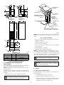
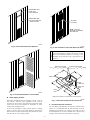
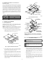
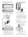
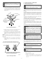
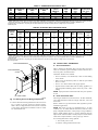
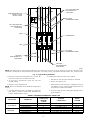
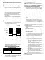
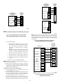
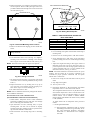
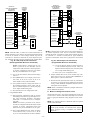
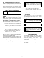
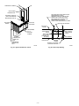
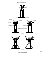
installation and
start-up instructions
MA1A
MH1A
10 SEER
RESIDENTIAL SELF-CONTAINED
AIR CONDITIONER/HEAT PUMP UNITS
Cancels:
New
II MA1A-18-1
12-95
NOTE: Read the entire instruction manual before starting the
installation.
SAFETY CONSIDERATIONS
Improper installation, adjustment, alteration, service, maintenance,
or use can cause explosion, fire, electrical shock, or other
conditions which may cause personal injury or property damage.
Consult a qualified installer, service agency, or your distributor or
branch for information or assistance. The qualified installer or
agency must use factory-authorized kits or accessories when
modifying this product. Refer to the individual instructions packaged with the kits or accessories when installing.
Follow all safety codes. Wear safety glasses and work gloves.
Read these instructions thoroughly and follow all warnings or
cautions attached to the unit. Consult local building codes and the
National Electrical Code (NEC) for special installation requirements.
Recognize safety information. This is the safety-alert symbol .
When you see this symbol on the unit or in instructions and
manuals, be alert to the potential for personal injury.
Understand the signal words DANGER, WARNING, and CAUTION. These words are used with the safety-alert symbol. DANGER identifies the most serious hazards which will result in severe
personal injury or death. WARNING signifies hazards which
could result in personal injury or death. CAUTION is used to
identify unsafe practices which would result in minor personal
injury or product and property damage.
Fig. 1—Model MA1A/MH1A
WARNING: Before installing or servicing system, always turn off main power to system. There may be more
than 1 disconnect switch. Turn off accessory heater
power if applicable. Electrical shock can cause personal
injury or death.
A95337
TABLE 1—UNIT SIZES AND AVAILABLE
ELECTRIC HEAT
UNIT SIZE
018
024
030
036
INTRODUCTION
The MA1A Air Conditioner and MH1A Heat Pump are UL Listed
per Standard UL 1995/UL 559 for use in manufactured homes.
These units are available in the cooling sizes shown in Table 1.
The MA1A and MH1A are single package units. All components
including outdoor coil, compressor, and refrigerant tubing are
located in 1 single package. The units are already piped, charged,
and wired.
Refer to Fig. 2 for basic unit dimensions.
BTUH COOLING
18,000
22,000
28,000
34,600
AVAILABLE KW
0—5—10
0—5—10
0—5—10—15
0—5—10—15—20
I. UNPACK UNIT AND INSPECT EQUIPMENT
Remove unit from carton and inspect for any shipping damage. Do
not install a damaged unit. Optional components used with unit
may include a thermostat, base and roof assembly kit, fresh air kit,
or return-air grille and air filter assembly.
Remove pallet by removing 4 bolts attaching pallet to base of unit.
CAUTION: The condensate drain outlet protrudes from
base of unit. To avoid damage to floors and floor
coverings, unit must be transported on an appliance dolly.
Do not slide unit on floor. Transport unit on appliance
dolly from side or rear only. Transporting unit from front
will damage air intake grille and lower coil. When setting
unit onto base template, unit may be carefully tilted from
front by a hand truck.
INSTALLATION
These units were designed for installation in manufactured homes,
but can be installed in a variety of other applications. These
instructions detail the method of installation for use in manufactured housing or other similar applications. Fig. 3 illustrates a
typical installation of this type. Study this drawing prior to starting
installation. It may be helpful to refer back to this drawing during
installation. Consult your distributor and the Application Guideline document for details regarding other installation applications.
—1—
11 9⁄16″
7 7⁄16″
5 1⁄4″
10 3⁄8″
6 7⁄16″
4 5⁄8″
ROOF
OUTDOOR-AIR
EXHAUST
8 9⁄16″
10 11⁄16″
WALL
THERMOSTAT
9 3⁄8″
5 3⁄4″
14″ INSULATED
FLEX DUCT
4 3⁄4″
4 15⁄16″
THERMOSTAT WIRES
FROM THERMOSTAT
BLOCK
14-IN. ROUND
BLOWER TOP
SCHEME NO. 1
20″
BLOWER TOP
SCHEME NO. 2
25″
PRIMARY
ELECTRICAL
SUPPLY
CONNECTIONS
ROOM AIR INTAKE
AND FILTER
OUTDOOR-AIR
PLENUM
INDOOR
PLENUM
INDOOR SUPPLY
DUCT
CONDENSATE DRAIN HOSE
(PIPE TO OUTSIDE OF STRUCTURE)
H
A95338
NOTE: If a door is used to enclose unit, refer to "Installation of
Unit Behind a Louvered Door or Enclosed in Closet" in Setup
section.
Fig. 3—Typical Installation
12 3⁄4″
3 11⁄16″
1 13⁄16″
•
8 No. 10 X 1/2 rust-resistant, self-tapping sheet metal screws
(holding roof flashing).
• Permanent sealant such as "mastic."
• 4 wood screws (base template).
• 2 No. 8 X 3/4 wood screws (unit to floor). Do not overtighten
and compress seal.
• Silicone caulking (roof flashing)
• Thermostat cable (18 gage wire minimum).
NOTE: The number of conductors needed depends on type of
unit and thermostat being installed. Air conditioning units require
4- or 5-conductor wire depending on type of thermostat being
used. (Some thermostats require a C terminal connection for
proper operation.) Heat pump units require 6-conductor wire.
6 13⁄16″
9 3⁄4″
9″
18 9⁄16″
DRAIN
5 1⁄2″
1 1⁄32″
18″
A95358
DIMENSIONS (IN.)
UNIT SIZE
018
024
030
036
H
57
57
67
67
BLOWER TOP SCHEME
Scheme No. 2
Scheme No. 2
Scheme No. 1
Scheme No. 1
CAUTION: Do not use thermostat wire with less than
the recommended number of conductors.
Fig. 2—Unit Reference Drawing
CAUTION: Failure to adhere to indoor air, outdoor air,
and exhaust air requirements as listed in the following
sections will void unit warranty.
II. ASSEMBLE SUPPLIES NEEDED FOR
INSTALLATION
The standard method of installation for units in manufactured
homes is with accessory base and roof assembly kit.
NOTE: If installing any other kit, Installation Instructions will be
furnished with kit.
In addition to items included in base and roof assembly kit, the
following items are required to install unit. All sizes listed are
suggested.
• Adhesive duct tape, U.L. 181 aluminum or equivalent.
III.
SETUP
A.
Indoor-Air Duct Requirements
The MA1A and MH1A units are designed to be installed in 1 of
the following ways:
1. Installed flush with the wall. (See Fig. 4.)
WARNING: Incorrect type of duct tape may be a fire
hazard. A failure to follow this warning could result in a
fire or explosion, and personal injury or death.
2. Recessed behind a louvered door. (See Fig. 5.)
3. Installed in a closet with 1 or 2 return-air grilles. (See Fig.
6.) Refer to Installation of Unit Behind a Louvered Door or
Enclosed in Closet section for grille sizes.
—2—
REMOVABLE WALL
PANEL FOR
UNIT'S SERVICE
REMOVABLE TRIM
FOR UNIT'S SERVICE
(DO NOT GLUE)
OPTIONAL
LOCATION
NOTE: THE UNIT
MUST BE ACCESSIBLE
FOR SERVICE.
A95339
Fig. 4—Unit Installed with Front Exposed
A95341
Fig. 6—Unit Installed in Closet with Return-Air Grille
CAUTION: The minimum installation clearance between both the indoor-air plenum and first 2 ft of metal
duct to any combustible material is 1 in. (See Fig. 7.) The
remainder of unit and duct work is approved for 0-in.
clearance.
INDOOR-AIR COLLAR
(12 11⁄16″ X 8 15⁄16″ X 9 1⁄4″ DEEP)
OUTDOOR-AIR PLENUM
(5 7⁄16″ X 17 15⁄16″ X 19 1⁄4″ DEEP)
251⁄4″
203⁄4″
DRAIN CUP
NT
O
FR
F
O
IT
UN
BASE
TEMPLATE
24″
METAL AIR
DUCT
FOAM
SEAL
24″
A95340
Fig. 5—Unit Installed behind a Louvered Door
B.
NOTE: DO NOT OBSTRUCT OUTDOOR-AIR PLENUM OPENING.
Indoor Supply Air Duct
A95342
The MA1A and MH1A units are designed to operate at a given
static pressure. The duct system, regardless of size, must not
exceed 0.3 in. static pressure. The design and construction of duct
system must also provide adequate air distribution to ensure
comfort levels throughout home.
If unit is being installed to replace another furnace or heating
system, a check of airflow rate (CFM) should be performed. If
airflow rate does not meet specifications, duct alterations or repairs
must be made to correct airflow problem.
Fig. 7—Indoor-Air Plenum and Duct Clearances
C.
Recommended Unit Clearances
For serviceability and elimination of compressor vibration transmission, it is recommended that the sides and back of unit be
installed with a minimum 1-in. clearance from walls. It is also
recommended that top of unit be installed with a clearance large
enough to allow removal of unit should it be necessary.
—3—
D. Installation of Unit Behind a Louvered Door or
Enclosed in Closet
WALLS
191⁄2″
181⁄2″
IT
PREPARE FLOOR AND BASE
A.
Install Installation Kit
FLOOR
FLOOR JOIST
FRAMING
HOME DUCT TRUNK
A95344
Fig. 9—Dimensions of Hole
FOAM AIR SEAL
FLAT-HEAD
WOOD SCREW
INDOOR AIR
COLLAR
Installing installation kit requires a hole through floor of home
approximately 18-1/2 in. wide by 19-1/2 in. deep to provide access
from unit to supply duct trunk and outside air.
NOTE: The diagrams show a typical installation. The actual
method of installation will be dictated by model and manufacturer
of the home. Installer will determine the best method to use.
DO NOT USE
FRONT INSIDE
HOLES
OUTDOOR AIR
PLENUM
BASE
TEMPLATE
BEND
ALTERNATE
TABS
INDOOR AIR
CUTOUT
13″ x 91⁄8″
1. Construct a boxed-in area of framework under unit location
slightly larger than the 18-1/2-in. by 19-1/2-in. hole to
provide adequate support for unit. (See Fig. 8.)
DUCT TRUNK
FLOOR JOIST
≈181⁄2″
UN
APPROX.
8″
NET FREE OPEN AREA (SQ IN.)
300
375
450
IV.
F
TO
ON
FR
TABLE 2—MINIMUM RETURN-AIR REQUIREMENTS
UNIT SIZE
018
024
030, 036
2″
2″ TYP.
If unit is installed behind a louvered door and louvers are directly
in front of unit’s intake grille, a 2-in. clearance is recommended
between door and front of unit. If louvers are installed in upper part
of door so they are not directly in front of intake grill, a minimum
7-in. clearance is recommended between door and front of unit.
This also applies if a solid wall is used instead of a louvered door.
Should the louver be installed somewhere other than in front of
unit (for example, to the side of unit), consult your distributor
before proceeding to obtain recommended clearances. The recommended minimum return-air requirements to be used are shown in
Table 2.
DRAIN CUP
91⁄8″
13″
DRAIN HOSE
(PIPE TO OUTSIDE
OF STRUCTURE)
NOTE: THE DRAIN CUP, FOAM AIR SEAL, OUTDOOR-AIR
PLENUM, AND INDOOR-AIR COLLAR ARE PREASSEMBLED
AT FACTORY.
≈191⁄2″
A95345
Fig. 10—Installation of Base Template, Indoor-Air Collar,
and Outdoor-Air Plenum
CAUTION: Be careful not to crimp drain hose attached
to condensate drain cup.
SUPPLY-AIR DUCT
CAUTION: Failure to route drain hose where it will not
be kinked will cause drain trap to overflow, leaking water
onto floor.
A95343
Fig. 8—Typical Framework Construction
5. Remove base template assembly. Reach through hole and
cut holes through vapor barrier and insulation for outdoorair plenum and condensate drain hose to extend through or
drain to outside. Also cut 13-in. by 9-1/8-in. hole in duct
trunk. (See Fig. 10.)
2. Locate supply duct trunk so that it runs under front edge of
hole. Back edge of supply duct trunk should be approximately 8 in. from back of hole. (See Fig. 9.)
3. After floor section is complete; locate, mark, and cut a hole
through floor approximately 18-1/2 in. by 19-1/2 in. (See
Fig. 9.)
6. Bend every other tab up 90 degrees on indoor-air collar as
shown in Fig. 10.
7. Insert base template assembly into supply duct and secure it
with 4 flat-head screws, 1 in each corner. Bend remaining
tabs up 90 degrees locking indoor-air collar securely to
supply duct trunk. Use mastic or foil-type duct tape to seal
any openings. (See Fig. 10.)
4. Place base template assembly over hole and mark indoor-air
plenum cutout in supply duct trunk measuring 13 in. by
9-1/8 in. (See Fig. 10.) Mark condensate drain hose and
outdoor-air plenum cutouts in insulation and vapor barrier
or drain to outside.
—4—
NOTE: Do not let indoor-air collar extend down into duct. It
MUST be flush with top of duct trunk. If collar does not fit
properly, minor adjustments may have to be made to collar.
8. Use Flex-Mend or equivalent RTV caulk to seal bottom
board to outdoor-air plenum.
TEMPORARILY COVER HOLE
WHILE THE 15-IN. CUTOUT IN
THE CEILING AND ROOF
ARE BEING MADE
WARNING: Non-foil-type tapes will not withstand the
temperature of heated air from unit and may be a fire
hazard. Failure to tape joint will allow heated or cooled
air to leak beneath home. A failure to follow this warning
could result in a fire or explosion, and personal injury or
death.
WOOD SCREWS
V.
INSTALL UNIT
A.
Setting Unit
CAUTION: Do not move unit on an unprotected floor.
Damage to floor will result.
1. If necessary, use an appliance dolly to position unit into
enclosure, being careful not to disturb foam seal on template. When unit’s front edge is in line with front edge of
base template, set unit upright onto base template. (See Fig.
11.)
NOTE: SCREW HOLES IN BOTTOM RAIL OF UNIT MUST
ALIGN WITH HOLES IN METAL BASE TEMPLATE.
A95348
Fig. 12—Securing Unit to Floor
4. Cover unit top as shown in Fig. 12. Cut a hole with a
diameter of approximately 15 in. through ceiling and roof
directly over outdoor-air exhaust. If hole in roof and ceiling
cannot be aligned directly over each other, a small bend in
the flexible duct may be required. Acceptable misalignment
of hole in ceiling and transition is a maximum of 2 in. per
each 12 in. of flex duct in elevation, up to a maximum of 6
in.
5. Seal any opening with mastic to prevent loss of conditioned
air into attic space.
B.
Exhaust Air Venting
1. Apply a generous amount of mastic to roof surface and
around hole cut for outdoor-air duct to pass through. (See
Fig. 13.) Lower duct down through hole in roof and ceiling
and fasten flashing to roof with screws.
APPLY MASTIC TO
SEAL ROOF CAP
TO ROOF
BASE TEMPLATE
15-IN. DIAMETER
HOLE
NOTE: TILT UNIT APPROXIMATELY 45° WHILE MOVING IT
INTO PLACE TO AVOID DISTORTION OF FOAM SEAL.
A95347
Fig. 11—Setting Unit on Base Template
CAUTION: Only minor movement is allowed when
aligning holes in unit base with holes in template to
prevent damage to foam air seal.
ROOF
2. Remove front grille of unit (if necessary) as shown in Fig.
12 and make minor adjustments in location of unit if
necessary to align screw holes in bottom rail of unit with
screw holes in base template.
3. The unit should be secured permanently to structure by
driving 2 wood screws through mating holes in bottom rail
of unit and base template into floor. Tighten screws flush to
foam seal. Overtightening screws will tip unit forward on
foam seal. Do NOT use any other procedure to permanently
secure unit to structure.
CEILING
A95349
Fig. 13—Outdoor-Air Duct Installation
2. Apply additional mastic or sealant around flashing perimeter base to provide protection against rainwater leaking
under flashing.
—5—
CAUTION: Failure to properly seal flashing to roof will
result in rainwater leaking into and damaging unit or
home. Proper sealing of roof vent is the responsibility of
installer.
VI.
MAKE ELECTRICAL CONNECTIONS
A.
Electrical Requirements
WARNING: To prevent personal injury or equipment
damage, always disconnect main power before doing any
maintenance or wiring. A failure to follow this warning
could result in electrical shock, fire, or death.
3. Check fit where flexible duct passes through ceiling. Seal
any openings with foil-type duct tape or caulking to prevent
loss of conditioned air to attic or attic air leaking into home.
(See Fig. 14.)
NOTE: All electrical power supply conductors serving unit must
be copper.
The circuit breakers or fuses used for branch circuit protection
should be UL Recognized. If circuit breakers are used, the circuit
breaker for compressor circuit must have a UL HACR rating. If
fuses are used, the fuses for compressor circuit MUST be a time
delay.
ROOF CAP
ROOF
All electrical wiring supplying unit must comply with the NEC
ANSI/NFPA 70, and all state and local codes.
ROOF
FLASHING
Depending on auxiliary heater size, unit must be supplied with 1,
2, or 3 separate 240-v circuits from home’s circuit breaker panel or
fuse box. Refer to Table 3 and Table 4 for required circuits and
recommended wire size for each circuit.
CEILING
TAPE APPLIED
TO SEAL HOLE
IN CEILING
The unit is equipped with circuit breakers enclosed in wiring
compartment. This compartment is located in top right-hand corner
of unit.
Ground wires for supply circuits must be attached to ground lug(s)
in circuit breaker box to provide required safety grounding of unit.
WARNING: The cabinet must have an uninterrupted or
unbroken ground according to National Electrical Code,
ANSI/NFPA 70 or local codes to minimize personal
injury if an electrical fault should occur. This may consist
of electrical wire or conduit approved for electrical
ground when installed in accordance with existing electrical codes. A failure to follow this warning could result
in an electrical shock, fire, or death.
A95350
Fig. 14—Roof Cap Installation
4. Remove protective cover from top of unit and inspect fan
housing to make sure no debris is in fan housing.
5. Push insulation up on lower end of flexible duct. Slip
flexible duct onto round adapter duct on top of unit and
secure duct to outdoor-air exhaust with mastic or U.L. 181
tape.
NOTE: An untaped or poorly taped joint will leak outside air into
home. All excess flex duct must be cut off and remaining duct
pulled tight.
WARNING: Failure to adhere to minimum wire sizes,
maximum over-current protection, disconnect, and
grounding requirements can cause personal injury, electrical shock, or a fire hazard. All wiring MUST comply
with requirements of the NEC, state, and local codes.
6. Pull insulation down over taped joint and outdoor-air
exhaust. (See Fig. 15.) Fasten insulation in place with tape
and strap.
All low-voltage thermostat wires MUST be connected to lowvoltage terminal block mounted on left side of control box located
inside front panel of unit.
PULL INSULATION AND OUTER COVER SNUG TO TOP
OF UNIT AND FASTEN WITH STRAP-TYPE DUCT CLAMP.
CAUTION: Power supply must be nominal 230-v, 1
phase. Do not exceed 253v or go below 197v.
SCREW
B.
Electrical Connections
WARNING: To avoid personal injury or death, do not
supply power to unit with compressor terminal box cover
removed.
IF POSSIBLE, INSERT A METAL SCREW W/FLAT
WASHER ABOVE WIRE FRAME OF FLEX DUCT TO
HELP HOLD IT ON ROUND ADAPTER.
1. Remove front panel.
a. Remove 2 screws on bottom.
b. Remove 5 screws holding cover around breakers and
remove it to gain access to wiring compartment. (See
Fig. 16.)
A95351
Fig. 15—Securing Insulation
—6—
TABLE 3—COMPRESSOR ELECTRICAL DATA
UNIT
SIZE
COMPRESSOR
AMPS
OUTDOOR FAN
AMPS
INDOOR FAN
AMPS
018
024
030
036
10.2
12.5
15.0
19.0
1.2
2.2
3.1
3.1
1.2
2.2
2.2
3.1
COMPRESSOR
CIRCUIT
AMPACITY
15.2
20.0
24.0
30.0
MINIMUM
WIRE
SIZE*
12
12
10
8
MAX WIRE
LENGTH
(FT)†
100
74
98
163
MAX FUSE‡
OR BREAKER
SIZE AMPS
15
20
30
40
* If wire is applied at ambient greater than 30°C (86°F), consult Table 310-16 of the NEC (ANSI/NFPA 70). The ampacity of nonmetallic-sheathed cable (NM), trade name
ROMEX, shall be that of 60°C (140°F) conductors, per the NEC (ANSI/NFPA 70) Article 336-30. If other than uncoated (non-plated), 60° or 75°C (140° or 167°F) insulation,
copper wire (solid wire for 10 AWG and smaller, stranded wire for larger than 10 AWG) is used, consult applicable tables of the NEC (ANSI/NFPA 70).
† Length shown is as measured 1 way along the wire path between the unit and the service panel for voltage drop not to exceed 2%.
‡ Time-delay fuse.
TABLE 4—ELECTRIC HEAT ELECTRICAL DATA
ELECTRIC
HEATER
(KW)
5
10
15
20
USED ON
Unit
Size
018
024
030
036
018
024
030
036
030
036
036
1ST CIRCUIT
2ND CIRCUIT
Amps
Ampacity
Wire
Size*
Max Fuse†
Size Amps
Max Wire
Length
(Ft)‡
Amps
Ampacity
Wire
Size*
Max Fuse†
Size Amps
Max Wire
Length‡
(Ft)
23.9
29.9
10
30
80
N/A
N/A
N/A
N/A
N/A
44.8
56
6
60
111
N/A
N/A
N/A
N/A
N/A
23.9
29.9
10
30
80
44.8
56
6
60
111
44.8
56
6
60
111
44.8
56
6
60
111
* If wire is applied at ambient greater than 30°C (86°F), consult Table 310-16 of the NEC (ANSI/NFPA 70). The ampacity of nonmetallic-sheathed cable (NM), trade name
ROMEX, shall be that of 60°C (140°F) conductors, per the NEC (ANSI/NFPA 70) Article 336-30. If other than uncoated (non-plated), 60° or 75°C (140° or 167°F) insulation,
copper wire (solid wire for 10 AWG and smaller, stranded wire for larger than 10 AWG) is used, consult applicable tables of the NEC (ANSI/NFPA 70).
† Time-delay fuse.
‡ Length shown is as measured 1 way along the wire path between the unit and the service panel for voltage drop not to exceed 2%.
N/A—Not Applicable
VII.
CIRCUIT BREAKER BOX
A.
INSTALL WALL THERMOSTAT
General Information
Select a location for thermostat about 5 ft above floor in an area
where air circulation is good. Preferably an interior wall near unit’s
return-air grille is the ideal location.
Thermostat should not be mounted:
• Close to a window, or an outside wall, or next to a door leading
to the outside.
• Where it may be affected by drafts or dead air spots behind
doors or corners.
• Close to or in direct airflow from supply registers.
• Exposed to direct radiant heat from sun, lamps, appliances, or
other temperature-radiating objects which may cause a false
reading.
NOTE: Improper location of thermostat will cause poor operation
of unit.
CIRCUIT BREAKER
COVER
FRONT PANEL
B. Route Thermostat Cable
All wiring for thermostat circuit must be No. 18 AWG minimum,
color-coded thermostat cable and comply with NEC, state, and
local codes.
Refer to Table 5 for type of thermostat cable required for specific
installation applications.
NOTE: Heat pump can only be controlled with a 6 or more
conductor, No. 18 AWG minimum thermostat cable and a heat
pump compatible thermostat. If heat pump is being installed to
replace another heating furnace or system, thermostat must be
replaced with 1 listed in Table 5 for heat pump use, and thermostat
cable must be replaced unless it is the proper type and size.
If an existing thermostat is being replaced:
A95352
Fig. 16—Gaining Access to Wiring Compartment
2. Connect electrical load and ground lead to unit as shown in
Fig. 17. Refer to previous section for electrical requirements. All low-voltage thermostat wires must be connected
to low-voltage terminal block mounted on side of control
box located inside unit.
1. Turn off all power to unit.
2. Remove existing thermostat from wall.
—7—
NO. 10 AWG AUXILIARY
5KW HEATER NO. 1
LOAD LEADS
SERVICE GROUND LUG
FOR NO. 10 AWG
AND NO. 8 AWG
NO. 8 AWG
COMPRESSOR LEADS
NO. 6 AWG AUXILIARY
10KW HEATER NO. 2
LOAD LEADS
10KW
5KW
ON
ON
ON
OFF
OFF
OFF
60 AMP
30 AMP
40 AMP
COMPRESSOR
NO. 8 AWG
COMPRESSOR LEADS
AUXILIARY
10KW HEATER NO. 2
LOAD LEADS
AUXILIARY
5KW HEATER NO. 1
LOAD LEADS
A95353
NOTE: This diagram shows a typical wiring installation for an 036 unit with 15-kw heat. It may not reflect the wiring in unit. The actual wiring
installation to use depends on unit and electric heat requirements. (See Tables 3 and 4.) The installer must follow NEC, state, and local codes.
Fig. 17—Typical Wiring Installation
3. Disconnect wires from existing thermostat, 1 at a time. Be
careful not to allow wires to fall back into wall.
If installing new thermostat cable, route as follows:
1. Drill hole for cable at location selected for thermostat.
4. As each wire is disconnected, record wire color and
terminal marking.
2. Remove front panel of unit.
5. Discard or recycle old thermostat.
NOTE: Mercury is a hazardous waste and MUST be disposed of
properly.
3. Route thermostat cable from unit’s compartment and pull
approximately 6-12 in. of cable through hole drilled in wall
for connection to thermostat terminals.
6. If existing thermostat cable is acceptable for application
(See Table 5), proceed to Mount Wall Thermostat and
Connect Thermostat Wires section.
4. Strip outer casing off area of cable pulled through wall for
greater flexibility.
TABLE 5—REQUIRED THERMOSTAT CABLE TYPE
APPLICATION
Air Conditioner
Heat Pump
THERMOSTAT
Robertshaw (TX400-42K)
TSTATPPNAC01-A
TSTATPPPAC01-A
Honeywell (T841A1548)
TSTATPPNHP01-A
TSTATPPPHP01-A
NO. OF
CONDUCTORS
REQUIRED
18 GAGE
4
5
5
6
8
8
—8—
REQUIRED
CONNECTIONS
G, R, Y, W
R, C, W/W1, Y/Y2, G
R, C, W/W1, Y/Y2, G
G, R, Y, B, W2, E
R, C, W/W1, Y/Y2, G, B, S1, S2
R, G, W/W1, Y/Y2, C, B, S1, S2
WIRING
DIAGRAM
Fig.
Fig.
Fig.
Fig.
Fig.
Fig.
18
19
20
21
25
26
C. Mount Wall Thermostat and Connect Thermostat
Wires
12. Set outdoor thermostat to 50°F.
NOTE: Refer to Installation Instructions packaged with thermostat for additional information.
Determine the type of thermostat needed for unit application and
follow instructions in the appropriate section below.
ELECTRONIC AIR CONDITIONING THERMOSTATS
(PROGRAMMABLE AND NON-PROGRAMMABLE)
ROBERTSHAW AIR CONDITIONING THERMOSTAT
1. Remove cover (friction fit) from thermostat body by gripping at top and bottom and lifting from subbase. Use
extreme care not to damage working parts.
1. Open thermostat rear door (mounting base) to expose
mounting holes. The base can be removed to simplify
mounting. Snap apart carefully at hinge to separate mounting base from remainder of thermostat.
2. Remove subbase from thermostat body by loosening captive screws.
2. Route thermostat wires through large hole in mounting
base.
3. Hold subbase level against wall in final thermostat location.
Mark wall with a pencil where screws will attach subbase to
wall. Use designated subbase mounting holes only.
3. Level mounting base against wall and mark wall through 2
mounting holes.
4. Set subbase aside and drill mounting holes in wall with
3/32-in. drill bit.
4. Drill two 3/16-in. mounting holes in wall where marked.
5. Route thermostat wires from hole in wall through opening
in center of subbase.
5. Secure mounting base to wall with 2 screws and anchors
provided, making sure all wires extend through mounting
base.
6. Attach thermostat subbase to wall using mounting screws
and predrilled holes in wall.
NOTE: Make sure white wire on thermostat subbase is connected
to A2 terminal.
6. Adjust wire length and routing to allow proper closure of
thermostat. Strip each wire end no more than 1/4-in. to
prevent adjacent wires from shorting together. Match and
connect equipment lead wire to correct terminals of the
thermostat connector. (See Fig. 19 and 20.)
NOTE: All TSTAT models have no batteries and are not "power
stealing." They do require 24 vac (R and C terminals) to be
connected for proper operation. Thermostat will not operate
without these 2 connections.
7. Strip approximately 1/2-in. of insulation off end of each
wire. Connect thermostat wires to appropriate thermostat
screw terminals on subbase. (See Fig. 18.)
CONTROL
VOLTAGE
TERMINAL
STRIP
THERMOSTAT
FAN
G
24VAC HOT
R
COOL
HEAT
Y
W
GREEN
RED
YELLOW
WHITE
7. Push excess wiring into wall. Seal hole in wall to prevent
drafts.
8. Snap hinge back together.
G
9. Turn on power to unit.
R
10. Reconfigure thermostat to energize fan (G) terminal
with call for heat (W).
Y
Since this is a self-contained unit, there is no furnace or fan
coil to energize the blower when electric heat is initiated.
The thermostat MUST be reconfigured to start blower when
electric heat is selected (G is energized whenever W is
energized).
a. Non-Programmable Model
W
A95354
NOTE: Connect only terminals shown to thermostat.
Fig. 18—Air Conditioner Circuit Connections
(Robertshaw Thermostat)
(1.) Enter thermostat configuration mode by pressing
and holding FAN button for approximately 10 sec.
The room temperature disappears and display
should read "1-." Thermostat is now in configuration mode.
NOTE: If FAN button is pressed again or if no
button is pressed for 60 sec, thermostat will exit
configuration mode and return to normal operation.
To re-enter configuration mode, the FAN button
must be pressed and held for 10 sec again.
8. Push excess wire back into wall. Seal hole in wall to prevent
drafts.
9. Mount thermostat body on subbase with captive screws.
10. Set heat anticipator indicator (located in upper left corner of
thermostat body) to appropriate value based on the heater
size for unit being installed. (See Table 6.)
(2.) Use up and down buttons until thermostat display
reads "5-."
TABLE 6—HEAT ANTICIPATOR VALUES FOR
AIR CONDITIONING UNITS
HEATER SIZE (KW)
0
5
10
15
20
ANTICIPATOR SETTING
N/A
0.16
0.16
0.32
0.32
(3.) Press MODE button once to display current selection of ON or OFF. Factory default is OFF.
(4.) Use the up or down button to change from OFF to
ON.
(5.) Press FAN button to exit configuration mode.
NOTE: Refer to electronic thermostat Installation Instructions for
more information if needed.
N/A—Not Applicable
11. Install thermostat cover. Carefully align "D" shaped dial
shaft with matching shaped hole in hub of setting dial, then
press cover carefully on thermostat body.
—9—
MODEL AC
PROGRAMMABLE
ELECTRONIC
THERMOSTAT
MODEL AC
NON-PROGRAMMABLE
ELECTRONIC
THERMOSTAT
CONTROL
VOLTAGE
TERMINAL
STRIP
24 VAC HOT
R
R
24 VAC COMM
C
X
HEAT STAGE 1 W/W1
W
COOL STAGE 1 Y/Y2
Y
FAN
G
CONTROL
VOLTAGE
TERMINAL
STRIP
24 VAC HOT
R
R
FAN
G
G
HEAT STAGE 1 W/W1
W
COOL STAGE 1 Y/Y2
Y
N/A
O/W2
N/A
Y1/W2
24 VAC COMM.
C
N/A
B
N/A
L
OUTDOOR
S1
X
G
SENSOR
A95413
CONNECTION
S2
NOTE: X terminal on control voltage terminal strip must be connected to C terminal on thermostat for proper thermostat operation.
A95414
NOTE: Terminals O/W2, Y1/W2, B, and L are not used on thermostat. X terminal on control voltage terminal strip must be connected to
C terminal on thermostat for proper thermostat operation. An optional
outdoor temperature sensor may be connected to S1 and S2 terminals
on thermostat.
Fig. 20—Air Conditioning Circuit Connections
(Programmable Electronic Thermostat)
Fig. 19—Air Conditioning Circuit Connections
(Non-Programmable Electronic Thermostat)
b. Programmable Model
(1.) Enter thermostat configuration mode by pressing
and holding FAN button for approximately 10 sec.
The room temperature disappears and display
should read "--." Thermostat is now in configuration mode.
NOTE: If no button is pressed for 10 sec, thermostat will exit configuration mode and resume normal
operation. To re-enter configuration mode, FAN
button must be pressed and held for 10 sec again.
CONTROL
VOLTAGE
TERMINAL
STRIP
THERMOSTAT
(2.) Press HOLD button to display current selection of
OF (off) or ON (on). Factory default is OF for off.
(3.) Use the up or down button to change from OF (off)
to ON (on).
(4.) Wait 10 sec to exit configuration mode.
NOTE: Refer to the electronic thermostat Installation Instructions
for more information if needed.
11. With an electronic thermostat such as this one, it should not
be necessary to change the factory default anticipation
setting. Consult thermostat Installation Instructions if heat
anticipation must be adjusted.
HONEYWELL HEAT PUMP THERMOSTAT
1. Strip approximately 1/2-in. of insulation off end of each
wire routed through hole in wall.
2. Connect thermostat wires to thermostat by placing colored
wire under appropriate terminal screw on back of thermostat as indicated by label over low-voltage terminal block
located on left side of control box. (See Fig. 21.)
3. Push all but approximately 2 in. of thermostat cable back
into wall. Seal opening around cable to prevent drafts
through hole which could interfere with operation of unit.
FAN
G
24 VAC HOT
R
COOL/HEAT
STAGE 1
Y
RVS HEATING
B
HEAT
STAGE 2
W2
EMERGENCY
HEAT
E
NOT USED
O
NOT USED
L
NOT USED
W3
GREEN
RED
YELLOW
BLUE
WHITE
BROWN
G
R
Y
B
W2
E
X
A95355
NOTE: Terminals O, L, and W3 are not used on thermostat.
Fig. 21—Heat Pump Circuit Connections
(Honeywell Thermostat)
—10—
4. Remove thermostat cover and place base against wall in a
near level position. Fasten to wall by driving 2 of the screws
provided with thermostat through slots in center of base and
into wall. (See Fig. 22.)
HEAT ANTICIPATOR INDICATOR
.12
.10
MOUNTING HOLE
LONGER
5
.1
.2
1.2 .8
.6
.4
.3
EM HEAT HEAT COOL COOL
A95357
Fig. 24—Setting Heat Anticipator
TABLE 7—HEAT ANTICIPATOR VALUES FOR
HEAT PUMP UNITS
HEATER SIZE (KW)
0
5
10
15
20
MOUNTING HOLE
A95373
Fig. 22—Thermostat Mounting Screw Location
5. Remove and discard foam shipping pad from inside thermostat.
ANTICIPATOR SETTING
N/A
0.35
0.35
0.70
0.70
N/A—Not Applicable
CAUTION: Failure to remove foam shipping pad will
damage thermostat.
4. Level mounting base against wall and mark wall through 2
mounting holes.
5. Drill two 3/16-in. mounting holes in wall where marked.
6. Level thermostat with a level. (See Fig. 23.) Tighten 2
mounting screws then drive 2 remaining screws through
holes in upper corners of base and into wall. (See Fig. 23.)
NOTE: Thermostat must be level for proper unit operation.
80
70
60
50
6. Secure mounting base to wall with 2 screws and anchors
provided, making sure all wires extend through mounting
base.
7. Adjust wire length and routing to allow proper closure of
thermostat. Strip each wire end no more than 1/4-in. to
prevent adjacent wires from shorting together. Match and
connect equipment lead wire to correct terminals of the
thermostat connector. (See Fig. 25 and 26.)
NOTE: All TSTAT models have no batteries and are not "power
stealing." They do require 24 vac (R and C terminals) to be
connected for proper operation. Thermostat will not operate
without these 2 connections.
80
70
60
50
EM HEAT HEAT OFF COOL
FAN AUTO
ON
A95356
Fig. 23—Leveling Thermostat
8. Push excess wiring into wall. Seal hole in wall to prevent
drafts.
7. Set thermostat heat anticipator to appropriate value based
on the heater size for unit being installed. (See Fig. 24 and
Table 7.)
9. Snap hinge back together.
8. Replace thermostat cover by hooking tabs on top lip of
cover into slots in top retaining post and swinging cover
down until it snaps over lower retaining post.
10. Turn on power to unit.
11. Reconfigure thermostat to allow thermostat and outdoor
temperature sensor to control electric heat lockout.
9. Set outdoor thermostat to 50°F.
NOTE: Refer to Installation Instructions packaged with thermostat for additional information.
This configuration allows lockout of any W (Electric Heat)
when outdoor temperature is above a selected value. Temperatures of 15° to 55°F (or equivalent values in °C) can be
selected. Feature can be enabled or disabled. EMERGENCY HEAT mode disables this feature. Factory default
is OFF (disabled.)
ELECTRONIC HEAT PUMP THERMOSTATS
(PROGRAMMABLE AND NON-PROGRAMMABLE)
1. Install Outdoor Temperature Sensor. Follow Installation
Instructions included with sensor and route wires through
hole in wall along with thermostat cable.
To enable feature and set temperature value proceed as
follows:
a. Non-Programmable Model
2. Open thermostat rear door (mounting base) to expose
mounting holes. The base can be removed to simplify
mounting. Snap apart carefully at hinge to separate mounting base from remainder of thermostat.
(1.) Enter thermostat configuration mode by pressing
and holding FAN button for approximately 10 sec.
The room temperature disappears and display
should read "1-." Thermostat is now in configuration mode.
3. Route thermostat wires through large hole in mounting
base.
—11—
MODEL HP
NON-PROGRAMMABLE
ELECTRONIC
THERMOSTAT
24 VAC HOT
R
R
24 VAC COMM
C
X
HEAT STAGE 2 W/W1
COOL/ HEAT
STAGE 1
FAN
MODEL HP
PROGRAMMABLE
ELECTRONIC
THERMOSTAT
CONTROL
VOLTAGE
TERMINAL
STRIP
Y/Y2
Y
G
G
24 VAC HOT
R
R
FAN
G
G
HEAT STAGE 2 W/W1
W2
CONTROL
VOLTAGE
TERMINAL
STRIP
COOL/HEAT
STAGE 1
Y/Y2
W2
Y
RVS COOLING O/W2
N/A
Y1/W2
E
24 VAC COMM.
C
X
RVS HEATING
B
B
TROUBLE
L
OUTDOOR
S1
E
RVS COOLING O/W2
N/A
Y1
RVS HEATING
B
TROUBLE OR
CLEAN FILTER
L
B
OUTDOOR
TEMPERATURE
SENSOR
SENSOR
S1
OUTDOOR
CONNECTION
SENSOR
CONNECTION
OUTDOOR
TEMPERATURE
SENSOR
S2
S2
A95416
A95415
NOTE: Terminals O/W2, Y1, and L are not used on thermostat. An
outdoor temperature sensor must be connected to thermostat terminals
S1 and S2. X terminal on control voltage terminal strip must be
connected to C terminal on thermostat for proper thermostat operation. Terminals W2 and E must be jumpered on unit terminal block.
Fig. 25—Heat Pump Circuit Connections
(Non-Programmable Electronic Thermostat)
NOTE: If FAN button is pressed again or if no
button is pressed for 60 sec, thermostat will exit
configuration mode and return to normal operation.
To re-enter configuration mode, the FAN button
must be pressed and held for 10 sec again.
NOTE: Terminals O/W2, Y1/W2, and L are not used on thermostat.
An outdoor temperature sensor must be connected to thermostat
terminals S1 and S2. X terminal on control voltage terminal strip must
be connected to C terminal on thermostat for proper thermostat
operation. Terminals W2 and E must be jumpered on unit terminal
block.
Fig. 26—Heat Pump Circuit Connections
(Programmable Electronic Thermostat)
(3.) Use the up and down buttons to change from OF to
1 of the available temperature choices. Value will
depend on ambient temperature at which heat pump
can no longer handle heating load.
(4.) Wait 10 sec to exit configuration mode.
(2.) Use up and down buttons until thermostat display
reads "6-."
12. Jumper terminals W2 and E on unit terminal strip. This
allows electric heat to be activated when EMERGENCY
HEAT option is selected at thermostat.
(3.) Press MODE button once to display current selection of OF, 15, 20, 25, 30, 35, 40, 45, 50, or 55.
Value should be OF for feature disabled.
13. With an electronic thermostat such as this one, it should not
be necessary to change the factory default heat anticipation
setting. Consult thermostat Installation Instructions if heat
anticipation must be adjusted.
(4.) Use up and down buttons to change from OF to 1 of
the available temperature choices. Value will depend on ambient temperature at which heat pump
can no longer handle heating load.
NOTE: Refer to Installation Instructions packaged with thermostat for additional information.
(5.) Press FAN button to exit configuration mode.
b. Programmable Model
D. Make Low-Voltage Connections at Unit
Attach thermostat wires to low-voltage terminal block on left side
of control box in locations indicated on label adjacent to terminal
block or appropriate thermostat wiring diagram in these instructions.
(1.) Enter thermostat configuration mode by pressing
and holding FAN button for approximately 10 sec.
The room temperature disappears and display
should read "--." Thermostat is now in configuration mode.
NOTE: If no button is pressed for 10 sec, thermostat will exit configuration mode and resume normal
operation. To re-enter configuration mode, FAN
button must be pressed and held for 10 sec again.
NOTE: Any unused conductors of thermostat cable not required
should be left unattached.
CAUTION: Recheck wiring color code schedule to be
certain proper terminals are connected before applying
power. Improper wiring or installation may damage
thermostat.
(2.) Press COPY PREVIOUS DAY button to display
current selection of OF, 15, 20, 25, 30, 35, 40, 45,
50, or 55. Value should be OF for feature disabled.
—12—
VIII.
ENSURE ADEQUATE OUTDOOR-AIR SUPPLY
CAUTION: The tunnel and grille or screen must meet
the minimum requirements listed in Table 8 to get the
proper airflow to the unit intake. Failure to adhere to this
caution will affect the unit’s capacity and efficiency
ratings. A larger net free area may be used.
Outdoor air is pulled from underneath the home, passed across the
outdoor-air coil, then pushed out through the roof cap exhaust.
Since the outdoor-air is pulled from beneath the home, it is very
important that the amount of ventilation panels or vents is
adequate. The underpinning vent panels or foundation vents are
rated for the amount of air that passes through them in sq in. of net
free area. Ensure that you have the correct amount of ventilation
needed for unit being installed. (See Table 8.)
3. Attach 1-in. duct board to frame built in item 1.
4. Seal all joints thoroughly with caulking and/or duct tape.
TABLE 8—VENTILATION REQUIREMENTS
UNIT SIZE
018
024
030
036
5. Set base of walls about 2 in. in ground and backfill around
to provide a good air seal. (See Fig. 28.)
MINIMUM NET FREE OPEN AREA (SQ. IN.)
400
450
675
700
6. Install a louver or a screen over opening of air tunnel where
it penetrates skirting or foundation of home.
X.
REFRIGERANT
The unit is pre-charged at the factory to the correct operating
charge and should not require adjustment. However, should an
adjustment be required or if the unit requires service, adhere to the
following precautions.
IX. CONSTRUCT OUTDOOR-AIR TUNNEL (IF REQUIRED)
NOTE: This is an OPTIONAL installation procedure to alleviate
problems that may occur with your air conditioner or heat pump
unit and various other appliances or ambient conditions.
WARNING: Gage ports are equipped with Schrader
valves. To prevent personal injury, wear safety glasses
and gloves when handling refrigerant.
A. Determine if an Outdoor-Air Tunnel is Required
We recommend that this procedure be used for any one or a
combination of the following conditions:
1. A fireplace is installed and gets its fresh air from underneath
structure.
CAUTION: Compressor damage may occur if system is
overcharged.
Indication to use: When conditioner or heat pump turns on,
smoke from fireplace backdrafts and enters structure.
2. A gas water heater is installed that uses fresh air from
underneath structure.
WARNING: Do not vent refrigerant to atmosphere.
Recover all refrigerant before system repair or final unit
disposal to avoid personal injury or death. Use all service
ports and open all flow-control devices, including solenoid valves.
Indication to use: When your air conditioner or heat pump
turns on, the pilot light for the water heater is blown out.
3. In extremely cold regions where water pipes may freeze.
Indication to use: In winter, pipes freeze.
B. Build Outdoor-Air Tunnel
NOTE: The equipment and materials to install this duct work are
NOT factory supplied, nor is manufacturer responsible for determining if this procedure should be utilized.
If it is determined that an outdoor-air tunnel is required, locate unit
air intake which comes through bottom board of home and build
outdoor-air tunnel as follows:
CARE AND MAINTENANCE
For continuing high performance, and to minimize equipment
failure, it is essential that periodic maintenance be performed on
this equipment. Consult your servicing contractor or User’s
Manual for the proper frequency of maintenance. Frequency of
maintenance may vary depending on geographic areas, such as
coastal application.
1. Using pressure-treated 2 X 2’s or similar material, frame a
tunnel from skirting or foundation wall to entrance of
outdoor-air plenum. (See Fig. 27 for a typical air tunnel.)
Leave User’s Manual with homeowner.
Explain system operation and maintenance procedures outlined in
User’s Manual.
2. The condensate drain must not be allowed to drain inside air
tunnel. Pipe to outside of home. (See. Fig. 28.)
—13—
THERMOSTAT WIRES
MAIN POWER
CONNECTIONS
NET FREE AREA (SEE VENTILATION
REQUIREMENTS TABLE)
SIZES MAY VARY AS LONG AS THE
MINIMUM NET FREE OPEN AREA
(INCLUDING GRILLE) MEETS THE
REQUIREMENTS LISTED IN
VENTILATION REQUIREMENTS TABLE.
RETURN-AIR GRILLE
(AIR FILTER BEHIND
RETURN-AIR GRILLE)
BOTTOM
BOARD
OUTDOOR
AIR INTAKE
OUTDOOR AIR PLENUM
BOTTOM
BOARD
1" DUCTBOARD
GROUND
GRILLE OR
SCREEN
CONDENSATE
DRAIN PIPE
HOME
SKIRTING OR
FOUNDATION
WALL
SEAL W/DUCT
TAPE AND/OR
CAULK
DRAIN PIPE
TO OUTSIDE
(CONNECT TO
OUTSIDE)
2" X 2"
TREATED
LUMBER
GROUND
SEAL W/DUCT
TAPE AND/OR
CAULK
1"
DUCTBOARD
2"X2"
TREATED
LUMBER
BACKFILL WITH DIRT
FOR GOOD AIR SEAL
A95383
Fig. 27—Typical Outdoor-Air Tunnel
A95384
Fig. 28—Drain Pipe Routing
—14—
DO'S AND DON'TS
18-IN. OFFSET
ALLOWABLE MISALIGNMENT
ROOFCAP
ROOFCAP
FLASHING
FLASHING
ATTIC AREA
ATTIC AREA
FLEX DUCT
FLEX DUCT
NOTE: THE FLEX DUCT SHOULD
BE A STRAIGHT RUN FROM UNIT
TO ROOFCAP.
TYPICAL FRONT VIEW
TYPICAL SIDE VIEW
DO'S
TYPICAL FRONT VIEW
TYPICAL SIDE VIEW
DON'TS
A95359
Fig. 29—Typical Installations
—15—
FINAL CHECKLIST
1. Make sure circuit breakers inside unit are in ON position.
c. Set system control to HEAT and raise temperature
selector to 80° or higher. On air conditioner models,
2. Check to see if hole in ceiling around 14-in. flex duct is
electric heat should energize. On heat pump models,
sealed or taped for a tight fit.
compressor should energize. Hot air should blow
3. Unit is secured to floor with 2 wood screws in groove under
through registers.
filter frame.
d. On heat pump models, set system control to EM HEAT
4. Condensate drain hose is below bottom board or piped to
(Emergency Heat). Compressor should turn off and heat
exterior of home.
should continue to flow from registers.
5. Outdoor-air intake is below bottom board and taped to
NOTE: Temperature of this emergency heat will be
bottom board so insulation or vapor barrier cannot be
about the same temperature as any other electric furnace.
sucked into outdoor-air intake.
9. Make sure no noise is in upper fan housing. If you hear
6. Roof flashing caulked and secured to roof.
knocking or flapping noise, turn unit off at thermostat and
7. Thermostat is level, packing pad removed (if applicable),
flip main circuit breakers to OFF position. Disconnect
and heat anticipator indicator is set to recommended value
14-in. flex duct on top of unit and make sure no sheet rock,
listed in Table 6 or 7 (unless electronic thermostat is used).
plywood, lumber, nails, or trash is in fan housing.
8. Test run in heating, cooling, and emergency heat (if
10. Homeowner package included with home.
applicable) mode as follows:
a. Set fan control to ON. If fan runs, return control to
11. Thanks for doing a PROFESSIONAL job.
AUTO setting. This verifies fan is working properly.
12. To ensure maximum performance, this unit requires 72 hr
b. Set system control from OFF to COOL. Lower temperaof run time.
ture selector to 50° or lower. The compressor should
energize and cool air should blow through registers.
Once cooling test is complete, return system control to
OFF setting. Wait 5 minutes.
© 1995 BDP Co. • P.O. Box 70 • Indianapolis, IN 46206
Printed in U.S.A.
—16—
ma1a181
Catalog No. 92-33MA-1A5B