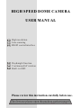
1
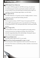
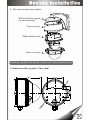
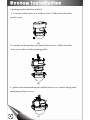
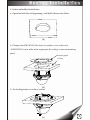
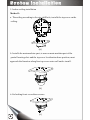
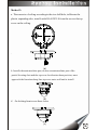
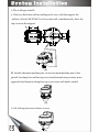
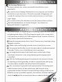
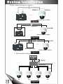
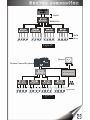
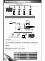
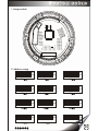
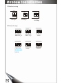
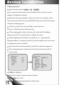
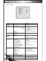
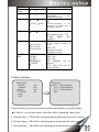
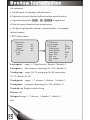
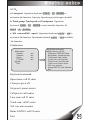
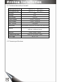
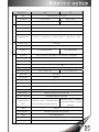
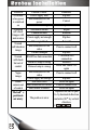
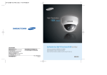
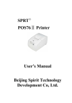
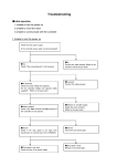
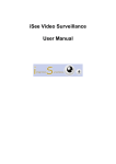
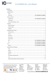
HIGH SPEED DOME CAMERA
USER MANUAL
High resolution
Line scanning
RS485 control interface
Day&night function
Continuous360 o rotation
Built -in OSD
Please review this instruction carefully before use.
LIST
1.Important safeguards------------------------------------------2~3
2. Features---------------------------------------------------------4
3. System installation---------------------------------------------5~11
4. System connection ---------------------------------------------11~14
5. System setup ---------------------------------------------------15~16
6. Description of functions --------------------------------------17~19
7.Menu setup------------------------------------------------------19~24
8. Technical data table------------------------------------------- 27
9.Troubleshooting----------------------------------------------- 28~30
-1-
All the safety and operation instructions should be read before the units is
operated.
This unit should be operated only from the type of power source indicated on
the marking label. If you are not sure of the type of powerDC12/1.5A supply you
plan to use, consult your appliance dealer or local power company. For units
intended to operate from battery power or other sources, refer to operation
instructions.
During the course of transportation, storage and installation, the product should
be avoided from incorrect operations such as heavy pressing, strong vibration etc.,
which can cause damage of product as there are sophisticated optical and
electronic devices inside the machine.
Do not attempt to disassemble the camera. In order to prevent electric shock,
do not remove screws or covers. There are no user-serviceable parts inside.
Always follow all electrical standards for safety when it is in operation. Adopt
the particular power supply which is provided with the unit. RS-485 and video
signal should keep enough distance with high voltage equipments and cables
when they are in transmission. Precautions for anti-lightning and anti-surging
should be taken if necessary.
The product should be indoor installed and operated to avoid rain and moisture.
Do not use it in wet places. If outdoor installation is needed, the closed protect
cover should be used and it is absolutely prohibited to use it in open air
independently.
Do not operate it in case temperature, humidity and power supply are beyond
the limited stipulations.
-2-
Do not let the camera aim at the sun or the object with extreme light what
soever it is switched on or not. Do not let the camera aim at or monitor bright
and standstill object for a long time.
Do not use aggressive detergent to clean the main body of the camera.
Wipe dirt with dry cloth. If needed, mild detergent can be used suitably.
Operate the intelligent speed dome camera with great care to avoid
shock or vibration. It operate incorrectly, the Speed Dome could be
damaged.
Do not place this unit on an unstable stand, tripod, bracket, or mount.
The unit may fall, causing serious injury to a person and serious damage
to the unit. Use only with a stand, tripod, bracket, or mount recommended
by the manufacturer or sold with the product. Any mounting of the unit
should follow the manufacturer's Instructions and should use mounting
accessory recommended by manufacturer.
If necessary, use a commercial lens cleaning paper to clear the lens
windows. Gently wipe the lens window until clean.
-3-
DNR (Digital Noise Reduction)
By using the DSP chip applied to the DNR technology, the amount of
low illuminance noise has been significantly reduced, and the signalto-noise ratio(S/N) as well as horizontal resolution has been improved,
resulting in a clear and sharp image display even in the dark.
10x Optical Zoom
The SDM-100 built-in x10 optical zoom lens is highly reliable. It feature
s Auto focus, Auto iris and Zoom Tracking function.
High Resolution
The horizontal resolution of 500TV Lines at Color mode and 570TV
Lines at BW mode can be achieved by using a high density CCD having
410,000 pixels SONY CCD, which provides clean, noiseless and reliable
pictures.
Day & Night (ICR)
An infrared(IR) Cut-Filter can be disengaged from the image path for
increased sensitivity in low light environments. The ICR will auto
matically engage depending on the ambient light, allowing the camera
to be effective in day & night environment.
Electrical Flip function
The SDM-100 has function of H/V reverse mode
Motion Detection(4 programmable zone per screen)
You can transmits an alert signal when it detects motion of an object on
the screen. This feature is useful when you have to monitor several screens
simultaneously.
-4-
1. The structure drawing explains
Walls install the support
(to choose fitting)
Top cover part
Main machine part
Front cover part
Attention
machine core Partial +Front cover= Main machine partial
2. Dimension of the product (Unit : mm)
-5-
3.packing gaskets backout method
a. Loosens on the front cover of three screws, Takes down the main
product part.
(a)
b. Loosens on the machine core part of three screws, Takes down the
front cover, takes out the packing gasket.
(b)
c. gathers the main machine part and the front cover, on the locking main
machine part three screws.
-6-
(c)
4. Indoor embedded installation
a. Opens the hole the ceiling among, with drills three screw holes.
(a)
b. Changes into PM4.0X45.0 the front cover three screws the screw
(PM4.0X45.0), puts in the main engine part the ceiling, to uneven mounting
panel.
Mounting panel
Ceiling
(b)
c. On locking front cover three screws
(c)
-7-
5. Indoor ceiling installation
Method 1:
a. The ceiling according to the size drill hole, installs the top cover on the
ceiling.
(a)
b. Installs the main machine part, to uneven main machine part of the
partial locating slots and the top cover localization bone position, must
approach the lineation along line top cover outer wall and to install.
(b)
c.On locking front cover three screws.
-8-
(c)
Method 2:
a. The concrete of ceiling according to the size drill hole, infiltrates the
plastic expanding tube, installs with KA4.0X35.0 from the screws the top
cover on the ceiling.
.
(a)
b. Installs the main machine part, to uneven main machine part of the
partial locating slots and the top cover localization bone position, must
approach the lineation along line top cover outer wall and to install.
c.
(b)
On locking front cover three screw
(c)
-9-
6.The wall type installs
a. Hits four holes the wall according to the size, with the support the
inflates of bolt (M8.0X80.0) to fix on the wall, simultaneously fixes the
top cover on the support.
.
(a)
B. Installs the main machine part, to uneven main machine part of the
partial locating slots and the top cover localization bone position, must
approach the lineation along line top cover outer wall and to install.
(b)
c. On locking front cover three screws.
-10-
(c)
The cleaning if down cover
To obtain constant clear videos, user should clean the down cover
periodically:
Be cautious when cleaning. Hold the down cover ring only to avoid direct
touch to the acrylic down cover. The acid sweat mark of fingerprint will
corrode the coating of down cover and scratch on down cover will cause
vague images.
Use soft dry cloth or the substitute to clean the inner and outer surfaces.
For hard contamination, use neutral detergent. Any cleanser for
high-grade furniture is applicable.
1
Lighting proof and surge signal proof
The product adopts TVS lightning proof technology to prevent from damage
by lightning strike below 1500 W and impulse signals such as surge; but it
is also necessary to abide by the following precautions to ensure electrical
safety based on practical circumstances:
Keep the communication cables at least 50 meters away from high voltage
equipment or cables.
Make outdoor cable laying-out under eaves as possible as you can.
In open area shield cables in steel tube and conduct a single point ground
to the tube. Trolley wire is forbidden in such circumstances.
In strong thunderstorm or high faradic zone (such as high voltage
transformer substation), extra strong lightning proof equipment must
be installed.
Take the building lightning proof requirements into account to design
the lightning proof and grounding of outdoor equipment and cable laying
-out in accordance with the national and industrial standards.
The system must be grounded with equal potentials. The earth ground
connection must satisfy the anti-interference and electrical safety
requirements and must not short circuited with high voltage electricity net.
When the system is grounded separately, the resistance of down conductor
should be
4
and the sectional areaof down conductor should be
2
25mm .
-11-
1.Single connection layout as follows:
RS485A+
A2
RS485A-
B2
......
SPEED DOME CAMERA
Keyboard
Figure1
RS485A+
A1
120
RS485B-
B1
......
SPEED DOME CAMERA
Keyboard
Figure2
RS485A+
A2
RS485B-
B2
RS485A+
RS485B-
......
Board gets stuck
SPEED DOME CAMERA
Keyboard
3
Figure3
2. Much machine links picture as follows:
Keyboard
A2 B2
1200M
HV1104
Distributor
RS485 BUS
1200M
1#
-12-
2#
3#
Figure4
4#
Keyboard
A2 B2
1200M
HV1104
Distributor
HV1104
Distributor
HV1104
Distributor
RS485 BUS
HV1104
Distributor
HV1104
Distributor
1200M
Speed Dome
1# 2# 3# 4#
5# 6# 7# 8#
9# 10#11#12#
13# 14#15#16#
Figure5
Monitor
Picture Conrtol Keyboard
HV1104
Distributor
HV1104
Distributor
HV1104
Distributor
HV1104
Distributor
16 screen processor
HV1104
Distributor
Speed Dome
1# 2# 3# 4#
5# 6# 7# 8#
9# 10#11#12#
13# 14#15#16#
Figure6
-13-
3.Main line connection diagram as follows:
RS485 Bus
Most far- end
ON
ON
ON
ON
Keyboard
1
1
120 OFF
1
120 OFF
1
120 OFF
120
OFF
Notice RS485 main line are most may the parallel control 256
intellectualizations high speed balls camera.
4.System wiring diagram as follows:
power Input
Monitor
Power IN
Video out
EXIT
SETUP
AUTO/PLAY
MODE
COLOR QUAD
1 2
3 4
F
RS-485
PROCESSOR
ZOOM
FREEZE
CH1
CH2
CH3
CH4
screen processor
Speed Dome
Matrix
RS485
Code Converter
RS485
Code Converter
RS485
RS485
Converter
BSW
AD Matrix
RS232/RS485
BSW
Philips Matrix
RS232
Keyboard
5. Explained:
1 The divider may connect 3.
2 In the ordinary circumstances, the ball machine 120 Omega is at the
OFF condition, if could not control, then should hit in the ON
condition.
3 The keyboard time passed (A2, B2) the road cannot control, then
traded the user to be able (A1, B1) a control.
4 RS485 main line transmitting range:
-14-
Baud Rate
2400Bps
4800Bps
9600Bps
19200Bps
Maximum Transmitting Distance
18 0 0 m
1200m
800m
200m
Space2
Baud rate
Switch
01 DC12V/1.5A
02 GND
03 RS485B
04 RS485A
05 VIDEO OUT
06 VIDEO GND
07 ALARM IN1
Address Switch
08 ALARM IN2
09 ALARM IN3
10 GND
1:120 End
2:Space1
3 4 5:
Protocol
000=PELCO_D
001=PELCO_P
010=VIEWSE
011=VIDO_B01
100=ALEC
101=LILIN
6:Space2
7 8:
Baud rate
00=2400bps
01=2400bps
10=4800bps
11=9600bps
Protocol
Switch
120 End
Resistance
Space1
1.Setup switch
ON=1 OFF=0
Address
00000000=0#
00000001=1#
00000010=2#
00000011=3#
00000100=4#
00000101=5#
00000110=6#
00000111=7#
00001000=8#
00001001=9#
00001010=10#
--11111111=255#
2.Address setup
ON
ON
ON
OFF
OFF
OFF
1 2 3 4 5 6 7 8
1 2 3 4 5 6 7 8
0#
1#
ON
ON
5#
ON
OFF
ON
OFF
1 2 3 4 5 6 7 8
6#
OFF
1 2 3 4 5 6 7 8
4#
1 2 3 4 5 6 7 8
ON
OFF
1 2 3 4 5 6 7 8
3#
9#
2#
ON
OFF
1 2 3 4 5 6 7 8
1 2 3 4 5 6 7 8
1 2 3 4 5 6 7 8
OFF
1 2 3 4 5 6 7 8
7#
8#
ON
ON
ON
OFF
OFF
OFF
1 2 3 4 5 6 7 8
10#
1 2 3 4 5 6 7 8
11#
-15-
3.Baud rate setup
DIP
DIP
DIP
7
7
7 8
8
2400bps
8
4800bps
9600bps
4.Protocol setup
3
4
5
PELCO_D
3
4
5
VIDO-B01
SUMSAMG
NEON
-16-
3
4
5
3
PELCO_P
3
4
ALEC
5
4
5
HTS
3
4
5
LILIN
Basic operation
NOTE: It will prolong to the ball life-span and improve to run precision
by operation joystick , Please bellow operation:
a.Do not run right-way when it is running left-way, do not run up-way
when running down-way. It is need to stop run when the ball will change
run way.
b.Do not shift speed soon, It is right operation for: slowest -> middling
speed -> flashest or flashes -> middling speed -> slowest.
c.Do not run long time: Line scan mode, Track scan mode or 360 o
1).UP, DOWN, LEFT and RIGHT run function
This speed can change when operation joystick to up run or down run or
left run or right run. The joystick is declining that the ball is celerity, it
is seven step speeds from slow to celerity.
2). Preset location
The ball can save 160 preset location (include ball up down left or right
location, camera zoom lens. It will auto run to preset location when call
1.1the save the location.
Save preset location
Operation keyboard: PRESET + N + ENTER
N: preset location number, range:0~79 100~179.
It will display :PRESET No. on screen.
It will display :OVER
SET
N: on screen if surpasses scope.
1.2Call preset location
Operation keyboard: Call + N + ENTER
It will display :CALL No: on screen.
It will display :NO-SET: No: on screen if do not save preset location.
It will display :OVER CALL N:on screen if surpasses scope .
-17-
Note :
The position is not nicety when Call preset location . Solution of two
kinds:
a.Hand control the ball machine to pass 0 O by horizontal direction ,
then arrives to 90O by vertical direction.
b. Enable the ball machine to return to the zero : Call + 99 + ENTER
Tt can adjust ball machine position error by above operation, then
operation to Save preset location
, the ball's position is nicety.
1.3.Dele preset location
Operation keyboard: PRESET + N + OFF
It will display :CLEAR No. on screen.
It will display :NO-SET: No on screen if do not save preset location.
It will display :OVER CLEAR N on screen if surpasses scope .
1.4 .Line scan mode
The ball can run between two preset location as for left-right monitor.
Set line scan mode start location: PRESET + 51 + ENTER
Set line scan mode end location: PRESET + 52 + ENTER
Run line scan mode: CALL + 51 + ENTER
Stop line scan mode: operation joystick stop to the ball.
Adjust speed : Main menu PTZ ball set Line speed
1.5 .Track scan mode
The preset locations can called by grouping way, it can setup pause time
between two preset location, the ball will arrive a preset then next preset
location that it is come into being loop monitor by run the TRACK
SCAN MODE. The feature is called TRACK SCAN MODE.
This ball setup 8 groups preset location, each group there are 10
locations. As follows:
-18-
0--9: the first group.
10--19: the second group.
20--29: the third group.
30--39: the fourth group.
40--49: the fifth group.
50--59: the sixth group.
60--69: the seventh group.
70--79: the eighth group.
Run Track scan mode: CALL + 53 + ENTER
It will jump to next one if the preset location done not save or dele.
Stop Track scan mode: operation joystick stop to the ball.
Direct run track SHOT + N + ENTER
Adjust speed
Main menu
Preset set
Track speed
1.6 .360 o mode
o
Start 360 mode AUTO + ON
o
the mode speed can changed at menu: PTZ Ball set => 360 speed.
Stop 360o mode AUTO + OFF or operation joystick stop to the ball.
-19-
1.Menu operation
Open the main menu by CALL + 95 + ENTER .
You can control the camera using keyboard directly, Please see the
manual of keyboard for details.
When the main menu display on the screen, the cursor display on the
left, operate joystick UP or joystick DOWN to the preset item for entering
submenu or charging item.
Operate joystick Tele, joystick Wide to enter the item.
Tele key or Wide key may as the enter key.
When changing the value of the item, the value will be flashing,
operate joystick UP, joystick Down to change the value.
When inputting some numbers or characters (i.e. inputting title,
changing address ), operate joystick left, joystick right to move the cursor
and change the value of each bit.
The menu will close automatically after 200 seconds non-operation.
The setting parameters in the menu will not lose after powered off.
2.system setup
Main menu
System
Camera
Alarm
PTZ Ball
Help
Exit
set
set
set
set
System set
Title
:CAMERA-1
Title Dis :on
Default :off
Restart :off
Address :001
Baud rate :2400bps
Protocol :PELCO-D
Format :PAL
Exit
a)TITLE:CAMERA-1
Editing title (Capital, number and punctuation).
b)TITLE DIS: ON/ OFF
Setting whether displaying the title on the bottom.
-20-
C)DEFAUIT:OFF/ON
camera factory default set. When the camera doesn't work properly for
the parameters changed, user can exclude the malfunction by restoring
the factory default set.
d)RESTART:OFF/ON
Restart camera. User also exclude the malfunction by restarting
the camera when it is working improperly.
e)ADDRESS:001
Change camera addr
ess(range: 0-255).When there are more than
one connected on the RS485 bus, user need to change the camera address.
The Camers will not be set on the same address.
f) BAUD RATE:2400dps
Setting the communication parameters baud rate.
including: 9600dps, 4800dps, 2400dps.
g) PROTOCOL:PELCO-D
Setting controlling protocol, including: PELCO-P, PELCO-D, HTS,
SAMSUNG,NEON,VIDO-BO1, ALEC, LILIN,
Notice: SAMSUNG,NEON,VIDO-B01 are same set to sw2.
h) Format: PAL. Select PAL if use PAL camera.
Select NTSC if use NTSC camera.
Camera default value: NTSC format.
NOTE:
e)ADDRESS,
f) BAUD RATE,
g) PROTOCOL
the 3 item can not change parameter on menu.
-21-
3.camera setupess.
Main menu
System
Camera
Alarm
PTZ Ball
Help
Exit
SETUP menu
CAMERA
TITLE
WHITE BAL.
BACKLIGHT
Motion
Detection
FOCUS
EXPOSURE
SPECIAL
RESET
-22- EXIT
Summary
Function
OFF ON
ATW
*Set camera Title String and OSD
Display Pos ition
Mode: OUTDOOR
INDOOR
AWC
MANUAL
OFF
LOW
HIGH
OFF ON
set
set
set
set
MIDDLE
MODE
ZOOM TRK
ZOOM SPEED
D-ZOOM
DISP ZOOM MAG
ZOOM POS INIT
LENS INIT
BRIGHTNESS
IRIS
SHUTTER
AGC
SSNR
SENS-UP
Refer to the bottom.
ATW is controlled 2 mode by color
temperature range
*Mode INDOOR:3000-10,5000 K
OUTDOOR:1,8000-10,500 K
*AWC :ONE PUSH
*MANUAL:RED / BLUE Adjustable
*Backlight compensation
*ON mode: AR EA(4 Progr ammable
zone/SIZE)
*Theword MOTION DETECT ED
appear on the screen.
*AUTO / MANUAL / ONE-PUSH
*ON / OFF
*FAST / SLOW
*OFF/ON(There is a D. Zoom limit of
x10)
*OFF / ON
*OFF / ON
*Execute lens initialization.
*The Brightness can be adjusted.
*AUTO / MANUAL
*--- / MANUAL / A.FLK
*OFF / NORMAL / HIGH
*OFF / LOW / MIDDLE / HIGH
*OFF / ON
*Returns to the leve l which was set by
the manufacturer for shipment.
*Saved all the se tting menu, then exits
Special menu
USER
PRESET
PRIVACY
Function
OFF ON
DAY/NIGHT
COLOR
BW
AUTO1
AUTO2
OFF
SYNC
Summary
No use
ON
INT
LL
CAM ID
COMM ADJ
DIS CAM ID
BAUD RATE
UART MODE
IMAGE
ADJ
FREEZE
H-REV
V-REV
SHARPNESS
COLOR
*ON
mode:
AREA(4
Programmable
zone)
/SIZE/TONE adjusta ble
*COLOR: COLOR FIX *BW:B/W
FIX
*AUTO1,2:According
to
the
luminance level, D&N filter is
automatically switched
*LL mode: you can adjust
desired phase from 0 -359
*Trigger
Signal:
Auto
Detection
*OFF/ON (Maximum length f or
the name displa y is limited 15
letters.)
*OFF / ON
Warning: don’t setup.
Warning: don’t setup.
*OFF / ON
*OFF / ON
*OFF / ON
*The Sharpness c an be
adjusted.
*The Color level can be
adjusted(0-100)
4.Alarm set menu
Main menu
System
Camera
Alarm
PTZ Ball
Help
Exit
set
set
set
set
Alarm
CH
CH
CH
Exit
set
1 :Not installed
2 :Not installed
3 :Not installed
Function note: Auto run to preset location and monitor to it and display
ALARM 1
on screen bottom when this ball is alarming. Input type:
a. Normal close
This ball is alarming when alarm interface have closed
b. Normal open
This ball is alarming when alarm interface have opened
c. Not installed
This ball is not alarming when alarm have not installed.
-23-
Set operation:
a. Install alarm, for example: infrared sensor.
b. Operation joystick that this ball run to alarm preset location.
c. Operation keyboard: CALL + 95 + ENTER to open menu.
d. Into sub-menu Alarm set item at main menu.
e. Set Input type depend on alarm's output interface. for example:
infrared sensor.
5.PTZ ball set menu
Main menu
System
Camera
Alarm
PTZ Ball
Help
Exit
set
set
set
set
PTZ Ball set
Line speed:
Line stop:
Track group:
Track speed:
Track stop:
Step Dis:
360 run
360 speed
Exit
4
003s
00-09
7
003s
on
off
3
Lines speed :
range: 1~7step slowest:1 flashest:7 default: 4.
Lines pause :
line run pause time range:0s~255s, default: 3s.
Track group: range: 00~79, min group: 00~09, max group:
70~79, default: 00~09.
Track speed:
range: 1~7, slowest: 1, flashest: 7, default: 7.
Track pause:
scan pause time range:0s~255s, default: 3s.
Track dis: on Display switch of step
360 run : off
360 speed: range: 1~7, slowest: 1, flashest: 7, default: 3.
Exit
-24-
NOTE
a. Line speed Operation keyboard: CALL + 51 + ENTER to
activation the function, Line stop Operation joystick stop to the ball.
b. Track group, Track speed and Track pause Operation
keyboard: CALL + 53 + ENTER to activation the function. Or
SHOT + N + ENTER
c. 360
speed Operation keyboard: AUTO + ON to
run and 360
activation the function. Operation keyboard: AUTO + OFF to disable
the function.
6.Help menu
Main menu
System
Camera
Alarm
PTZ Ball
Help
Exit
set
set
set
set
Keyboard command
Open menu: call 95
Clear pre: PREnoff Close
Set preset: preset n enter
Call perset :call n enter
Line s can: call 51 enter
Track s can: call 53 enter
Track n run: shot n enter
360 run: auto on
Home GOTO 0: call 99 enter
Exit
Keyboard command
Open menu: call 95 enter
Clear pre: pre n off
Set preset: preset n enter
Call preset: call n enter
Line scan: call 51 enter
Track scan: call 53 enter
360 run: auto on enter
Home GOTO 0: call 99 enter
Exit
-25-
8.1.Technical data table of the ball
Manual speed( Pan/Tilt)
Min: 1.5
/s
Max: 120
/s
Auto speed( Pan/Tilt)
Min: 1.5
/s
Max: 240
/s
Pan range
360
Tilt range
0-90
160 presets
Preset location
Track scan mode
8 cruises, 7 step speeds
Line scan mode
1 cruises, 7 step speeds
360
run mode
OSD system
7 step speeds
Setup Parameter, Setup Title, XY position ,Auto Clear Screen
Protocol
Baud rate
Communications mode
Power supply
8.2.Camera specifications
-26-
PELCO-D PELCO-P HTS, ALE C, LILIN ,
VIDO-B01, SUMSANG, NEON
9600bps, 4800bps, 2400bps
RS485 bus, max distance: 1800m
DC12V/ 1.5A
Specifications
NTSC
PAL
C
Size
C
Total Pixels
811(H) x 508(V)
795(H) x 596(V)
D
Effective Pixels
768(H) x 494(V)
752(H) x 582(V)
O
Optics
10X , f = 3.8 to 38.0mm(F1.8)
P
Min . Focus Distance
1,000mm
T
D.
1/4 inch, Inter line Transfer CCD
ZOOM
OFF/ON(X2~X10)
I
C
Angle Field of view
H : Appr . 51.2 (Wide) to 5.58
(Tele)/V : Appr.39.3
(Wide) to 4.27
(Tele)
S
s
Scanning System
2: 1 Inter lace
y
Synchronization
Internal/VD-Lock
n
Frequency
H:15.734KHz/V:59.94Hz
H:15.625KHz/V:50Hz
c.
Resolution
500 TV Lines(Min.):Color (WIDE) / 570 TV Lines(Min.) : B/W(WIDE)
Min. Illumination
0.7 Lux / F1.8(50 IRE); Color / 0.02 Lux / F1.8 (50 IRE) ; B/W
S/N(Y signal)
50 dB (AGC Off ,Weight ON)
Video output
Focus
CVBS : 1.0Vp-p/75
Auto/Manual/One push
Zoom Movement Speed
1.67 sec : Wide to Tele
1.75 sec : Wide to Tele
E
IRIS Control
Auto, Manual
L
Lens Initialize
Built-In
E
Camera Title
OFF/ON(Displayed 15 characters)
C
Camera
T
Day & Night
Auto1, Auto2,COLOR,B/W(ICR)
R
Gain Control
Normal, High, OFF Selectable
I
White Balance
C
ID
Back Light Compensation
255 ID Selectable
ATW/AWC/Manual (1800
LOW/MIDDLE/HIGH/OFF Selectable
A
L
K~10,500 K)
AUTO(X128~ 1/50sec~ 1/120,000sec)
Electronic shutter
AUTO(X128 ~ 1/60sec ~ 1/120,000sec) Sens-up
speed
and Sens-up Limit is selectable, Flicker less
Sens-up and Sens-up Limit is selectable,
Flicker less
O.S.D
Built-In
Motion Detection
ON/OFF(4 Programmable Zone per Screen)
SSNR
Low, Middle, High, Off
Privacy Function
ON/OFF(32Zones,It consists of 8Group 4Programmable Zone per Screen)
FLIP
Vertical , Horizontal
, Vertical-Horizontal
, OFF Selectable
-27-
Problems
No action
when power
is switched
on
Abnormal
self-check.
Images with
motor noise
Normal
self-check no
image
Normal
self-check
but out of
control
Vague
image
Dome
camera out
of control
The ball s
position is
not nicety
-28-
Possible Causes
Power supply fault
Bad connection of the
power
Transformer damaged
Mechanical failure
Camera inclined
Remedies
Replace
Power supply not enough
Replace
Video signal fault
Bad connection of the
video
Camera damaged
Reinstall
RS485 bus bad connection
Dome ID setup is wrong
Protocol setup is wrong
Bad connection of the
video
Power supply not enough
Self check error
Bad connection of control
Bad control of matrix
The position is error
Correct
Replace
Repair
Reinstall
Press to connect well
Replace
ChecktheRS485
connection
Reselect
Reset and Switch ON
again
Press to connect well
Replace
Power on again
Press to connect well
Power on again
1.opration the ball to pass
0 by horizontal direction
and arrive 90 by vertical
direction.
2. Call+99+enter.
Dome can run,
But camera can’t
TELE, WIDE or do
not open the menu
The camera has fault,
.It needs to reset
Shake out hood cover,
then find out five test
position on the PCB(refer
).
underside picture
1 Short circuit GND to
SET position by wire.
camera menu will open.
2.Short circuit GND to
SET position by wire.
Move the cursor to
RESET item.
3.Short circuit GND to
SET position by wire,
Reset the camera.
SET
RIGHT
LEFT
UP
DOWN
GND
PCB
-29-