1
Chapter 2
Hardware Setup
Chapter 2:
Hardware Setup
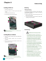
Cutout
Preparing the Hardware Installation
Notch
To access some components and perform certain service
procedures, you must perform the following procedures
first.
Note:
WARNING: To reduce the risk of personal injury,
electric shock, or damage to the equipment,
remove the power cord to remove power from the
device. The Power On/Standby button on the back
panel does not completely shut off system power.
Portions of the power supply and some internal
circuitry remain active until AC power is removed.
1. SO-DIMM
installed must meet the following
requirement: non-ECC DDR-III 800 MHz. Do not
install DIMMs with different speeds.
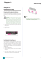
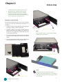
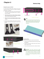
1. Unscrew the 4 screws from the top cover of the FW7540 System.
2. Open the cover.
Installing the System Memory
The motherboard supports DDR3 memory that features
data transfer rates of 800MHz to meet the higher
bandwidth requirements of the latest operating system
and Internet applications. It comes with one double
data rate type three (DDR3) Dual Inline Memory Module
(DIMM) socket.
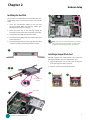
1. Open the DIMM socket.
1. Align the memory module’s cutout with the DIMM’s
slot notch.
2. Install the memory vertically into the socket by
applying force to both ends of the DIMM evenly.
Network Application Platforms
5