1
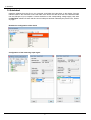
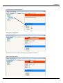
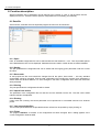
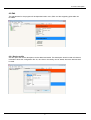
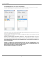
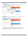
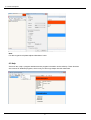
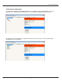
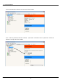
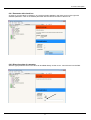
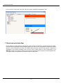
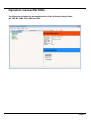
Operation manual PM-TOOL
Configuration software for parameterisation of the following display lines:
M1, M2, M3, PM5, PU5, PW5 and PZ5
PM-TOOL_GB.pdf Update: 06.03.2015
Software
Contents
1.
Brief description
1
2.
Scope of delivery
1
3.
System requirements
1
4.
Installation instructions
1
5.
Quickstart
2
6.
Function description
4
6.1. Data file
4
6.1.1 Open
4
6.1.2 Saving
4
6.1.3 Save under
4
6.1.4 Closing
4
6.1.5 Import from device
4
6.1.6 Printing
4
6.1.7 Last opened data files
4
6.1.8 Finish
4
6.2. Edit
5
6.2.1 Device profile
5
6.2.2 Characteristic line of the device (setpoint table)
6
6.2.3 Parameter lock
7
6.2.4. Extras (Shows connection to PC)
7
6.3. Help
8
6.4. Parameter adjustments
9
6.4.1 Parameter with check box
11
6.4.2 Direct insertion of parameter
11
7.
Read and write data files
12
8.
Terms of use
13
1. Brief description / 2. Scope of delivery / 3. System requirements / 4. Installation instructions
1. Brief description
With the PM-TOOL configuration software the device lines M1, M2, M3, PM5, PU5, PW5 and PZ5 can be
parameterised via a PC. With this tool the device configuration can be generated, readouted and safed on
the PC. Due to the easy to handle program surface, the parameter can be changed, whereat the
operating mode and the possible options are preset by the program.
2. Scope of delivery
Contains the software on CD and one USB cable with device adapter.
3. System requirements
The PM-Tool software is a PC software, suitable for system software Windows XP, Windows VISTA or
higher and runs under .NET Version >=2.0. Required is a PC with USB interface.
Advice:
The communication with the indicator can be carried out via an optional RS232/RS485 interface or via the
configuration interface using the provided USB cable. The USB cable provides another COM interface,
which can be in general automatically installed via the internet. If required the driver ca be found on CD,
too (directory "USB-Driver").
This new COM interface needs to be selected in the program under menu item "Extras/Settings". Under
„Port“ a selection of possible interfaces is given.
Device configuration and the current settings can be read out via menu „File/Import from device". The file
can be safed on the PC after the desired settings have been made. This device configuration is not
readable for all kind of device types and versions. In this case a suitable control file is required as XML,
which needs to be loaded via the dialog „File – Open“.
During the first communication with the indicator make sure that the correct device address is adjusted in
the menu line. It is always set on 1 in delivery status.
The PM-Tool uses only the ModBus-ASCII protocol. Changing to ModBus-RTU and back is only possible
manually via the front keypad of the display.
4. Installation instructions
The software installation on the CD happens via "setup.exe".
For software operation „.Net“ is needed, which can be installed afterwards, too, if desired. This must be
confirmed in the installation dialog.
1
5. Quickstart
5. Quickstart
Install the software from the CD on your computer, and follow the instructions on the display. Plug the
interface cable in the red socket on the rear side of the device and the other end of the interface cable
into the USB port of your computer. Connect the device to the corresponding voltage supply. Now start
the PM-TOOL software. Ensure that the correct COM port has been selected (see picture 6.2.4 "Extras“
on page 7.
Readout the configuration of the device
Configuration of the measuring input signal
2
5. Quickstart
Configuration of switching points
Saving the configuration
Remove the connection cable. The device is now ready for operation.
Reset to factory setting
3
6. Function description
6. Function description
With this software, sets of parameter can be read out from a device or a PC or can be written into the
display from the PC. Therefor a device-specific configuration file is necessary (xml data file).
6.1 Data file
Via menu item „Data file“ the most important program functions can be carried out.
6.1.1 Open
Here, an available configuration file can be selected with the valid extension „*.xml“. Thus all possible options
of the desired device line can be displayed. Parameter that were read or written at last are made recallable.
6.1.2 Saving
The just opened device configuration file can be saved with the ongoing given parameter under the current
file name.
6.1.3 Save under
At new projects the file name should be changed first via the option „Save under…“, this way standard
original data cannot be changed. Thus the total configuration file including the currently given parameter is
saved under the declared data file. To avoid changes in the basic configuration files, save such data files
write-protected!
6.1.4 Closing
The just opened device configuration file will be closed.
6.1.5 Import from device
The parameter of the configuration file are read out from the indicator into the PC. Thus the correct COM
interface needs to be adjusted.
6.1.6 Printing
Under menu item „Printing“ the current parameter can be printed out in a formatted overview on a windows
printer.
6.1.7 Last opened data files
The four last opened data files are provided for direct call and can be opened by simply clicking on.
6.1.8 Finish
The program PM-TOOL is finished. If the configuration had been changed, then a dialog appears if the
current configuration shall be safed.
4
6. Function description
6.2 Edit
The adjustments for the program will be deposited under menu „Edit“ and the supporting point table can
be edited.
6.2.1 Device profile
Via this option the device description can be edited and safed. This description should contain all relevant
information about this configuration file. So, the client or the facility can be stated, where the devices shall
be used.
5
6. Function description
6.2.2 Characteristic line of the device (Setpoint table)
The option „Characteristic line of the device" is used only by special types of indicators. If this option is
available, supporting points can be parameterised by insertion or removing.
In the upper area it is shown, which measuring input has been selected at the moment. Below follows the
table, in which all supporting parameter are listed.
Afterwards follows in the meantime the corresponding display value. Below follows the table, in which all
supporting parameter are listed.
Then the corresponding display value follows in the same line. List here, which value shall be shown in the
display before the analog input value. To add or remove new supporting points, the line needs to be
selected first (see above). Via the right mouse button the contect menu can be called up. This enables the
insertion or removal of a parameter. By insertion respectively removal, a new line before the selected line
will be highlighted in blue. Offset and final value cannot be removed, as these parameter mark the start and
the end of the linearisation.
Caution! The analog values are stated with positions after decimal point, whereat they need to be
separated by a decimal point! Furthermore linearisations that have been generated in Excel can be
imported, if they were saved in CSV format. That way complex functions can be calculated in Excel (e.g.
different types of tanks) and later on transferred into the indicators.
After the linearisation is completed, it can be taken over.
6
6. Function description
6.2.3 Parameter lock
To protect parameter against misapplication a password can be assigned (maximum 32 signs). Parameter
can only be changed and safed by entering the password.
6.2.4 Extras
Under „Characteristic line of the device“ the serial COM address can be selected, which will be used for
communication between the PC and the indicator.
Via a check box available COM addresses can be selected. A standard PC comes in general with two
COM interfaces. Using a laptop, generally a USB-RS232 Gateway is used. The driver of the gateway
simulates a RS232 interface, so that a COM-Port feely assigned and runs with this software, too.
7
6. Function description
Note:
For device type M1-xS please adjust a Baudrate of 1200.
6.3 Help
Via menu item „Help“ a program assistance and a program information can be called up. These functions
are common for Windows programs, which is why we will not go deeper into this matter here.
8
6. Function description
6.4 Parameter adjustments
The menu tree is used like the Windows Explorer. If a „+“ stands in front of the description, a group of
parameter can be selected via this description. This is comparable to a Windows Explorer directory.
Via double-click on the identifier or a simple mouse-click (left mouse button) on the scroll-down button,
the following level can be opened.
9
6. Function description
On the parameter level there are no more scroll down buttons.
Once a device parameter has been selected, a parameter information and the parameter values are
shown on the right side of the window.
10
6. Function description
6.4.1 Parameter with check box
As soon as „current value" is clicked on, an overview window appears in the lower corner on the right with
available parameter. Click on the desired parameter with the left mouse button to take it over.
6.4.2 Direct insertion of parameter
With this type parameter the current value can be edited directly via the cursor. Just click once into the field.
11
7. Read and write data
If a too small or too big value was given, then the insertion field will be highlighted in red.
7. Read and write data files
During reading or writing data the parameter are read out from the indicator or transferred into the display.
In the process the parameter will be changed directly in the device. If the configuration of the device should
get lost, it can be restored by a reset to the default values (see user manual of the device). A function for
cancellation of the writing processes does not exist. Thus it makes sense to save configurations in the
PM-TOOL. Please note, that the software saves only the parameter which are given in the configuration file.
A complete saving of all parameter in the device does not take place!
12
8. PM-TOOL – terms of use
8. PM-TOOL – terms of use
8.1 Usage
The software PM-Tool was developed for usage with a Windows-PC from up version XP only. It may only
be used in combination with the device lines of the manufacturer respectively copyright owner. Every
usage with other devices or assembly groups is forbidden.
8.2 Copyright
8.2.1. The installation of the software is only allowed via the available data compilation.
8.2.2. The dublicating of the complete data carrier or hard disc storage unit of the computer is only allowed
for data backup reasons.
8.2.3. The modification of the installation or the creation of modified data carrier for the software is
forbidden.
8.2.4. The transfer of the software to a third person is only allowed in combination with the corresponding
digital indicator, as well as the orignal installation carrier.
8.2.5. An unregulated distribution of the software, complete or in parts via the internet or data carrier is
forbidden and will be avenged as copyright infringement.
8.2.6. The number of installations, which may be created via an existing original installation medium is not
limited.
8.2.7. The derived control files in XML format are not subject of copyright, as long as they are used in
connection with the digital indicators of the copyright owner.
8.2.8. All text and contents on this medium are protected by copyright.
8.3 Program code
The program code of the software may not knowingly be changed, neither on an installation medium, nor
on a computer. Thereby it is irrelevant, if the application is used commercial or private.
8.4 Warranty
The manufacturer assumes no liability for damages occured by usage or installation of the software. The
software has been checked accurately by the manufacturer. The manufacturer assures that at the time of
compilation of the installation files, no fawlty effect of the software was known.
8.5 Support
8.5.1. A claim for support has only the original purchaser.
8.5.2. A claim for updates at no charges is not provided.
8.5.3. An exception to 8.2. Copyright is, if the current version is fawlty or the usage with the corresponding
and provided indicator is not possible. In this case the customer has a claim for an improved
respectively updated version. The manufacturer is given a period of up to 6 weeks after
information of the defects for rework.
8.5.4. If the customer should purchase an indicator at a later date, which may not be supported by the
current software version, then this will not lead automatically to a claim for an update at no charge.
It can be granted on a voluntary basis.
8.6 Exclusion
If the specified menu items if the terms of use should have no or only a limited legal validity, then this has
no impact on the validity of the remaining menu items of the terms of use.
13
PM-TOOL_GB.pdf
Update: 06.03.2015