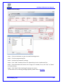
1
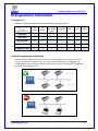
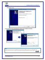
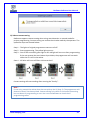
DediProg User Manual 07/2014 Dediware Software User Manual Version 2.0 © DediProg Technology Co., Ltd 2014 All Right Reserved. Dediware Software User Manual Table of contents: I. General Description ..................................................................2 II. System Requirements ...............................................................2 2.1 Hardware support ...........................................................................................................................2 2.2 Operating System Requirement..................................................................................................2 III. Programmer information ..........................................................3 3.1 Support IC ..........................................................................................................................................3 3.2 Multi-programmers Capability ....................................................................................................3 IV. Dediware Installation................................................................4 V. Dediware Introduction ..............................................................6 5.1 Open Dediware ................................................................................................................................6 5.2 Software Interface ..........................................................................................................................7 VI. Engineering Mode................................................................... 12 6.1 Select .................................................................................................................................................12 6.2 Load ...................................................................................................................................................14 6.3 Config Setting .................................................................................................................................25 6.4 Programming function .................................................................................................................26 6.5 Save Project.....................................................................................................................................28 VII. Production Mode .................................................................... 29 7.1 DownPrj ...........................................................................................................................................29 7.2 Run Project ......................................................................................................................................30 7.3 Stop Prj .............................................................................................................................................31 7.4 CLI&API Control .............................................................................................................................31 VIII. FAQ ........................................................................................ 32 IX. Revision History ...................................................................... 36 Important notice: This document is provided as a guideline and must not be disclosed without the consent of DediProg. However, no responsibility is assumed for errors that might appear. DediProg reserves the right to make any changes to the product and/or the specifications at any time without notice. No part of this document may be copied or reproduced in any form or by any means without prior written consent of DediProg. www.dediprog.com 1 Dediware Software User Manual I. General Description This user manual illustrates how to install and use DediProg Dediware Software with DediProg programmers. Dediware is innovative and easy to use software that supports StarProg Engineering and ProgMaster Production series programmers. Dediware has all the necessary functions, including basic functions like read ID, read, blank check, program, verify, batch and advanced function like protection, auto-start, and standalone project which commands are also available. Dediware has two different modes dedicated to different types of needs. Engineering mode is a specific mode to help engineers to test and develop. Production mode can control several programming devices simultaneously and individually to achieve the best productivity. All updates and further versions of Dediware software are free to download and can be found on DediProg official website: www.dediprog.com II. System Requirements 2.1 Hardware Support Dual-core CPU or above 100GB Hard drive or above 1GB of RAM or above USB 2.0 ※ For eMMC or NAND IC programming , the faster hardware requirements the better. 2.2 Operating System Requirements Windows 8.1 Windows 8 Windows 7 Windows Server® 2008 Windows Vista® Support both 32-bit and 64-bit OS www.dediprog.com 2 Dediware Software User Manual III.Programmer Information 3.1 Support IC Dediware software supports the following DediProg programmers. TYPE SPI Flash SPI NAND Parallel Nor/NAND Flash EEPROM StarProg-F ◎ ◎ ◎ ◎ StarProg-U ◎ ◎ ◎ ◎ ◎ ◎ ◎ StarProg-ATE* ◎ ◎ ◎ ◎ ◎ ◎ ProgMaster-F4/8 ◎ ◎ ◎ ◎ ProgMaster-U4/8 ◎ ◎ ◎ ◎ Programmer MCU CPLD eMMC ◎ ◎ ◎ ◎ ◎ *Support standalone mode. 3.2 Multi-programmers Capability Same product models can be driven by one PC or notebook at the same time. The correct connection is shown in Fig. 3-1, the PC connected with all ProgMaster-F4 programmers. Fig 3-2 shown incorrect connection since the StarProg and ProgMaster cannot be connected by 1 PC. Fig. 3-1 Same model programmers can be connected by one PC Fig. 3-2 Different model programmers cannot be connected by one PC www.dediprog.com 3 Dediware Software User Manual IV. Dediware Installation Insert the installation CD or download the installation software from DediProg official website: www.dediprog.com/download 4.1 Run Dediware software 4.2 Select a destination folder to save the installation files, as shown below. www.dediprog.com 4 Dediware Software User Manual 4.3 Click “Finish” to close the window or check the “Install Device Driver “ to install the programmer driver. 4.4 Programmer driver and Dediware software are installed successfully. Note: If you owned StarProg or ProgMaster programmers, please make sure to upgrade your firmware version to 2.x.x before installing new Dediware software. Please refer to VIII. FAQ www.dediprog.com 5 Dediware Software User Manual V. Dediware Introduction 5.1 Open Dediware Double-click to open Dediware. Dediware is based on Client-Server technology. The Dediware icon will shows in the windows taskbar. Dialogue box will show the Client login message. Click OK to connect with Server. If an error message appears, please refer to VIII.FAQ www.dediprog.com 6 Dediware Software User Manual 5.2 Software Interface 5.2.1 Main menu A. Language:English, simplified Chinese and traditional Chinese. B. Socket:Set and check the number of times the socket adaptor is used. www.dediprog.com 7 Dediware Software User Manual a) Socket > Set Limit Count: Setting the numbers of times socket adaptor is used. Software will pop up the message when socket adaptor reaches the number of times in the settings. This function helps to ensure the quality control of socket adaptor especially when used in the production programming. b) Socket > Counts:Check the status of each socket adaptor. C. Help: Offers the firmware manual update information, easy to open Windows calculator, user manual and shows the Dediware version. www.dediprog.com 8 Dediware Software User Manual 5.2.2 Toolbar The toolbar includes icons for quick access to the majority of the functions. Please refer to VI.Engineering Mode for detail introduction. 5.2.3 Programmer Status Window This area indicates the status of every programming programmer. For example as shown below, the red frame shows two ProgMaster-U4 statuses, including model name, firmware version and serial number(S/N).The Site#1~4 show each socket adaptor status. The Blink and Start function can only be set during production mode after downloading the project. Blink:All lights on the programmers will be on. Use when several programmers are connected. Up/down button Start:When Start Mode is in manual, click button to start the production programming. :Set the orders of programmers. The top is the first programmer. *Please note that, Dediware software only accept that same programmer model connected at the same time. www.dediprog.com 9 Dediware Software User Manual 5.2.4 Log Window A. B. C. A. Log Window: Log window records all progress information and steps made which can be saved to the installation folder automatically. Click “Save Log “to save as a new file .Click “Clear Log” to clean the log window and record to a new file. B. File Check Sum: After downloading the programming file, the file checksum and file name will show in the table. Several files loaded at the same time will be shown in the table based on their priority. C. ProjectName / ProjectCheckSum: After downloading programming project, the project checksum and project name will show here. www.dediprog.com 10 Dediware Software User Manual 5.2.5 Information window A. B. C. A. Chip Info: Type: IC type Manufact: IC manufacture Size: Memory size Package: IC package PartNum: Part number ID: Chip ID ADP P/N1~3: Socket adaptor part number B. Statistics: Statistics Window indicates the number of successful, unsuccessful (Failure), and total programmed chips. C. Batch Config Setting: Batch Config Settings contain information of batch and start mode setting. www.dediprog.com 11 Dediware Software User Manual VI. Engineering Mode Engineering mode offer the programming, verify and testing functions. Users can turn project file to the production mode. 6.1 Select: Choose IC manufacturer /part number /package If the manufacturer is known, user can select the chip type and manufacture directly. The related IC part numbers will show in the chip list. Search IC by typing IC part number in the field circled by the blue frame. It is recommended to choose “All” in the “Chip Type” and “Manufacture” to avoid limiting the search results. The input field has the memory function to store 5 sets of IC part number that can be selected by pressing the button on the right. Double-click selected IC in chip list. The searching process is not case-sensitive. Search Input Field Fig. 6-1 www.dediprog.com 12 Dediware Software User Manual Log window will show the successful message as shown below after choosing the IC. IC information will also shows in the ChipInfo window. www.dediprog.com 13 Dediware Software User Manual 6.2 Load Select icon Load to load the file intended for the programmer. According to different IC type, the file settings will divide into normal IC, eMMC and NAND Flash. 6.2.1 Normal IC Programming Settings User can load one or several files at the same time. File Format:The format of programming file. File Checksum:File checksum File Offset:Set the address to start loading to buffer File Path:Shows the path of programming file. Partition Name:If the IC has more than one memory that can be programmed, the partition names can be selected in this drop-down list. (e.g. IC has Flash and OTP memory and the partition name list will have these two options.) StartProgAddr:Select the file to programmer Buffer. When loading several files to the same partition, make sure that the memory address is set well to avoid covering the original date. ProgramLen:The file size. FillUnuseByte:Check the box to assign Unused Byte .The default value is 0xFF. Reset:Clear all programming files in the image list. Del:Delete the selected file in the image list. Add:Add the programming file to the image list. www.dediprog.com 14 Dediware Software User Manual Load File Steps: Step1:Click on the button to open the load file dialogue box. Step2:Find the programming file. Step3:Confirm the parameter setting. Step4:Click “Add” to add the file to the list. Repeat Step 1 to 4 to load more files. Step5:Files information will show in the “ImageList”, if not, click “Del” or “Reset” to restart setting. Step6:Click “Next” after checking all settings are correct. ※ Once the error or warning message appears, please refer to VIII. FAQ www.dediprog.com 15 Dediware Software User Manual Step7:Summary window shows all setting information. www.dediprog.com 16 Dediware Software User Manual 6.2.2 eMMC Programming Settings User can load one or several files at the same time. (From left to right) File Format:The format of programming file. File Checksum:File checksum File Offset:Set the start address to start loading to buffer File Path:Shows the path of programming file. Skip Blank Value:Check the box to check the blank data and skip the blank when programming. Reduce the programming time. Partition Name:eMMC offers UserArea,Boot1Area and Boot2Area. Sector index:Set the start address of eMMC sector. Sector count:The total number of programming sector. Reset:Clear all programming files in the image list. Del:Delete the selected files in the image list. Add:Add the programming file to the image list. www.dediprog.com 17 Dediware Software User Manual eMMC Load File Steps: Step1:Click button to open load file dialogue box. Step2:Find the programming file. Step3:Confirm the parameter setting. Step4:Click “Add” to add the file to list. Repeat Step 1 to 4 to load more files. Step5:Files information will show in the “Image List” window, if not, click “Del” or “Reset” to restart setting. Step6:Click “Next” after checking all settings are correct. ※ Once the error or warning message appears, please refer to VIII. FAQ www.dediprog.com 18 Dediware Software User Manual Step7:Set ext CSD Step8:Summary window shows all settings information. www.dediprog.com 19 Dediware Software User Manual 6.2.3 NAND Flash Programming Settings A. Use Partition File: Support CSV, DEF and MBN formats.CSV is Comma Separated Values Format, DEF is Group Define File Format and that MBN is Qualcomm Multiply Partition Format. B. Custom: Set the information of programming file. www.dediprog.com 20 Dediware Software User Manual a) Select “Custom” to set programming file. b) Load NAND Flash File function User can load one or several files at the same time. File Format:The format of programming file. File Checksum:File checksum File Offset:Set the address to start loading to buffer File Path:Shows the path of programming file. SpareArea UseFile:Check the function to enclose the SpareArea with file. Partition Name:Only Flash option can be selected. Block index:Setting the start of block. Block count:Total block number of programming. Reset:Clear all programming files in the image list. Del:Delete the selected files in the image list. Add:Add the programming file to the image list. www.dediprog.com 21 Dediware Software User Manual c) NAND Load File Steps: Step1:Click on the button to open the load file dialogue box. Step2:Find the programming file. Step3:Confirm the parameter settings. Step4:Click “Add” to add the file to list. Repeat Step 1 to 4 to load more files. Step5:Files information will show in the “Image List” window, if not, click “Del” or “Reset” to restart setting. Step6:Click “Next” after checking all settings are correct. ※ Once the error or warning message appears, please refer to VIII. FAQ www.dediprog.com 22 Dediware Software User Manual Step7:BBM Settings A. B. A. BBM Configuration: Set it according to the number specified at Load File. As the above figure shows, two Image files need BBM, EccUnitSize, EccAlgorithm, and MaxErrorBit settings. BBM:Bad block management. EccUnitSize:The unit size of ECC. In this case, 2112 Byte is used as the unit. EccAlgorithm:ECC calculation. MaxErrorBit:Set the maximum error bit of each unit. In this case, for 2112 Bytes, 1 bit error is allowed. B. Guarded Area Configuration: For setting NAND Flash bad block. First, Guarded Area Index is 1; Block0 to Block9 do not allow bad block. Second, Block 10 to Block 999 can allow 10 bad block. If one of these two conditions is met in the programming process, this IC will be considered as a failed IC. www.dediprog.com 23 Dediware Software User Manual Step8:Summary window shows all settings information. Save the settings by click “Save Partition File”. Select “Use Partition File” to load the file next time. Note: NAND Flash programming function includes the BBM and ECC setting.If user cannot find the suitable BBM and ECC for programming setting.Please contact DediProg. www.dediprog.com 24 Dediware Software User Manual 6.3 Config Setting 6.3.1 Batch Settings User can double-click or click to select options or click to remove. 6.3.2 StartMode Setting To meet user needs, Dediware offer three production modes. A. Start from Manual Mode: Click “Start” in Dediware or press the start button on programmer, the production mode will be activated. B. Start from Auto Detection: Dediware will detect inserted chip and start to program automatically after running the RunPrj. C. Start from Handler:This function is suitable for DediProg automatic system. Note: Programmer has the auto IC contact testing function in manual and auto detection mode. Users must pick out the IC on the socket adaptor after programming. Please refer to VIII. FAQ www.dediprog.com 25 Dediware Software User Manual 6.4 Programming function Move mouse over the site and do right-click. The programming function will shows as the red frame. 6.4.1 Single Socket Adaptor Read ID:Read the ID of IC and shows in ChipInfo. Read Memory:Read the IC data and compare with the file date. Please refer to 6.4.3 Read Memory. Erase Whole Chip:Erase whole IC memory. If IC has several memories which can erase single area memory. Blank Check:Check if the target chip is blank or not. Program Chip:Writes the selected file data into the chip. Checksum Verify:Content verification between chips and loaded file. Auto Batch:Run the programming settings of batch in Config. 6.4.2 Function Activation Timing Not select IC Selected IC Selected IC And load project Selected IC ,load project, setting Config/Batch Read ID Read Memory Erase Whole Chip Blank Check Program Chip Checksum Verify Auto Batch Action Function ※When doing the project programming, the single socket function will be disabled. www.dediprog.com 26 Dediware Software User Manual 6.4.3 Read Memory Open Read Memory as shown below. In this case, it is program eMMC . A. .C .B .D .E .F A. Area Select If the selected IC has parts of memory, the user can switch the memory area after Read memory. The area function is eMMC in this case. B. File Window (Buffer) Files contents will be displayed in this area. C. Chip Window Chip contents will be displayed in this area. The data will automatically compare with file data and show the differences in red color. D. Next Different Dediware will indicate the differences between the loaded file and edited file. E. Goto User can assign Dediware to go to the address the user wants to examine by entering line number into the column. F. Save Save the chip data of each partition. www.dediprog.com 27 Dediware Software User Manual 6.5 Save Project After Load File, Config settings and verification, Dediware is ready to save to project for production use. Click SavePrj and the window shows below, click OK to save the file. After saving the file, Dediware will ask for downloading the project to programmer. If yes, the project will download to SD card and switch to production mode. Otherwise select No to close the software. www.dediprog.com 28 Dediware Software User Manual VII. Production Mode Production function as below, Save Prj:Save the programming file, batch and start mode settings as a programming project for production use. DownPrj:Download the project to the SD card which is inserted to the programmer. The transmission is more stable and faster by a SD card than an USB. SelectPrj:Select the project in the SD Card. RunPrj:Run the project. StopPrj:Stop the project. Normal Steps: Load project > Select Project > Run Project > Stop Project 7.1 DownPrj:Download and select project. Ensure that the SD card is inserted to the programmer before downloading the file to it. Select the file and click “OK”, then the file will be downloaded to the SD card. www.dediprog.com 29 Dediware Software User Manual Dediware will select the file which the user downloads to the SD card previously as the default. If this is not your programming file, use “SelectPrj” below, to re-select as shown After selecting the file, the window will show IC information, batch setting, Start Mode, File Checksum, ProjectName and ProjectCheckSum. 7.2 Run Project Dediware will detect every socket site status after clicking” Run Prj”. If there is no socket adaptor on the site, the log window will shows in yellow color. When programmer is ready for production, Dediware will program by the start modes selected by the user before. A. Start from Manual Mode: Click “Start” in Dediware or press the start button on programmer, the production mode will be activated. B. Start from Auto Detection: Dediware will detect inserted chip and start to program automatically after running the RunPrj. C. Start from Handler:This function is suitable for DediProg automatic system. www.dediprog.com 30 Dediware Software User Manual 7.3 Stop Prj: Click on “Stop Prj” to stop project programming. 7.4 CLI & API Control DediProg provides users with detailed API for software redevelopment so users can easily integrate our programmers with 3rd party automation such as ATE. Please contact with DediProg for further information. www.dediprog.com 31 Dediware Software User Manual VIII. FAQ Q1. The message box shows up when opening Dediware 1. Plug in new programmer or the order has changed, please reset the programmer order. The orders of programmers have been changed, restart Dediware. Computer does not detect any programmer, check the power of computer. USB disconnected. 2. Query Device info failed or count is zero, please check if the ProgMaster has plug in. Check the power of programmers. USB disconnected. Check if the USB drivers have been installed. Programmer firmware does not match with Dediware software. Please update the Dediware version. www.dediprog.com 32 Dediware Software User Manual 3. Please contact DediProg when you see this unusual message. Q2. Right-Click can’t execute any function after inserting socket adaptor? Please select Menu>Socket>Socket count to confirm the socket adaptor information. If socket adaptors do not show any following information that means socket adaptor disconnected or the control IC of socket adaptor has broken. Please contact DediProg. Q3. Programmer doesn’t detect the socket adaptor on the programming site after run project? Please refer to Q2 to check the socket information. Maybe socket adaptor is disconnected or control IC is broken. Q4. Do I have to pay extra fee to upgrade my Dediware or programmer firmware? DediProg offers FREE software and firmware update once users buy StarProg-F / U and ProgMaster series programmers. User can download the latest software on DediProg website. www.dediprog.com 33 Dediware Software User Manual Q5. How to upgrade my programmer firmware? New Dediware version (3.x.x) has to use the 2.x.x firmware version. 1.If firmware version is 1.x.x,please refer to the following steps for update. Step 1:Install the new version of Dediware and the firmware (2.x.x) will be in the installation folder. Step 2:Close the Dediware and open the old Dediware version. Step 3:Going to Menu > Help > Firmware Manual update the firmware to 2.x.x version. Step 4:Restart programmer and open the new Dediware to confirm the firmware version. 2. Firmware version is 2.x.x The pop-up message shown below occurs when user opens Dediware after installing the new version of Dediware. Please update firmware with the following steps. Step 1:Going to Menu > Help > Firmware Manual Update and select firmware (2.x.x) to update. The new firmware file will be saved to installation folder. Step 2:Turn off the programmer power and turn on again. Open new Dediware and check the firmware version. Q6. Message warning when loading files? 1. Selected file size is bigger than partition size. Press OK will truncate the file to fit the partition space. But Dediware does not check the data importance. 2. When the user load several files which will overwrite the old files. Please make sure the size and memory address of each file do not overlap each other. www.dediprog.com 34 Dediware Software User Manual Q7. About contact testing Dediware supports contact testing when using auto detection or manual mode for project programming. Contact testing can reduce the mistake made by the operator. The operation steps are showed below. Step 1:The lights of original programmer status are all off. Step 2:Start programming. The yellow light turns on. Step 3:One of the successful green light or fail red light will turns on after programming. If the user presses the start button by accident, the programmer will not work while the IC is still in the socket. Step 4:All lights will turns off after picking up the IC. Contact testing will start working after running the” RunPrj”. Note: If user only pressed the socket down but not pick up the IC (Step 3). The programmer will determine that IC has been picked. Contact testing only check IC and socket connecting but not detect IC programming or not. User can use Dediware to check the IC programming status. www.dediprog.com 35 Dediware Software User Manual IX.Revision History Date Version Change 08/28/2013 1.0 Initial release 05/26/2014 1.1 Remove MCU Prog / StarProg ATE(Flash) Separate StarProg to StarProg-F and StarProg-U 07/29/2014 2.0 New Dediware software release DediProg Technology Co., Ltd - Taiwan Headquarter TEL: 886-2-2790-7932 FAX: 886-2-2790-7916 4F., No.7, Ln. 143, Xinming Rd., Neihu Dist., Taipei City 114, Taiwan - Shanghai Office TEL: 86-21-5160-0157 FAX: 86-21-6126-3530 Room 503, Block E, No.1618, Yishan Road, Shanghai, China Technical Support:[email protected] Sales Support:[email protected] www.DediProg.com Information furnished is believed to be accurate and reliable. However, DediProg assumes no responsibility for the consequences of use of such information or for any infringement of patents or other rights of third parties which may result from its use. Specifications mentioned in this publication are subject to change without notice. This publication supersedes and replaces all information previously supplied. All rights reserved Printed in Taiwan. www.dediprog.com 36