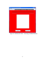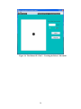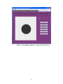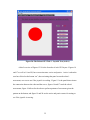
1
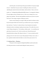
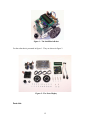
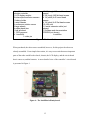
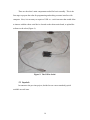
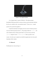
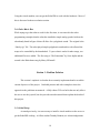
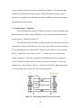
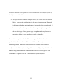
Bluetooth Robot Remote Joystick Control
[email protected]
satnet.fgcu.edu/~jsummerh/
csidc.fgcu.edu/jsummerh/
Florida Gulf Coast University
Professor: Janusz Zalewski
CEN 3213 Embedded Systems
Date Modified: February 20th 2009
1
Table Of Contents
1. Preface: User Manual:
a. Initial Setup
i.
Disclaimer
ii.
Software
iii.
Hardware
2. Section 1: Introduction..................
a. Problem introduction
i.
Initial Setup
ii.
Robotic Basics – Hardware
iii.
Joystick
iv.
Robotic Basics – Software
v.
Robo-Music Box
3. Section 3: Problem Solution ..................
a. Initial Setup
b. Robotic Basics – Hardware
c. Robotic Basics – Software
4. Conclusion………
5. Appendix
6. Acknowledgements ..................
7. Reference
2
Preface: User Manual
This user manual is designed for the next university student or hobbyist that might have
an interest in this project. Direction, disclaims, and caution will be given to the user who
decides to undergo the continuation of this project. If any problems arise, all the needed
information to contact me is on the title page of this document. Please note that all of the
work has been completed for the wiring of the Bluetooth modules, firmware
configuration for the modules which is displayed in figure 14, and acquiring the needed
Java software libraries for the joystick and the serial ports [reference 7 and 8]. Thus
instruction will be given on the current information needed for installment.
*Disclaimer*
Instruction will not be giving on how to program the Ridgesoft robot [reference 1], nor
how to install the Java programming environment of choice, nor instructions on how to
assemble the robot. Instruction on robot assembly should not be needed since the one
given to the user should be assembled and so should proper installment of the Bluetooth
modules. There will not be given any instruction on using the Java programming
language, this knowledge should be assumed before attempting the project. The chosen
Java programming environment for this project was Netbeans [reference 6]. These are
things that can either be easily acquired knowledge by visiting the required websites, or it
is at the current user’s discretion of the preferred Java programming environment.
*********************************** End of Disclaimer **********************************
3
I. Initial Setup
This guide will consist of two parts: the hardware required for setup, and the
required software for installment. Figure i will list the needed requirements.
1. The Ridgesoft robot with Bluetooth module installed visible in figure 11.
2. The serial cable that will connect to the user’s computing device of choice in
figure 13, and example could be a server, laptop, or personal pc.
3. The Javajoystick and the RXTX Java libraries which can be acquired and
downloaded using references 7 and 8.
4. This requirement maybe optional. If the current computing device the user is
working with does not have a serial port, then a serial-to-USB device will need to
be acquired like in figure 5. Once acquired, install the required software to use
this device.
5. His or her Joystick of choice that can be acquired locally similar to the one in
figure 6.
6. Finally, it is highly advisable that the user acquire a Java programming
environment of choice; Netbeans [reference 6] is the example of choice in the
project. The user is encouraged to use one he or she prefers.
Figure i: List of requirements.
I.a Software setup
This section will guide and direct the current user, which could be a university
student or computing hobbyist, the required steps for writing robot programs that will be
uploaded to the robot Handyboard [figure 4], or adding the required Java libraries to the
4
Java development environment to create an application that will run on the computer that
will wirelessly communicate with the robot. Therefore the user needs to be aware that to
create software that will wirelessly control the robot, there needs to be two applications
created: one application will be running on the user’s computer that will be sending data
to the application running one the robot, and the application running on the robot
Handyboard [figure 4] receiving data from the application running on the computer. The
following information lists the steps needed to setup and deploy the software
requirements for deployment of the wireless application.
1. Visit the Ridgesoft website [reference 1], and download the RoboJDE in figure 8.
This will allow the user to compile, and deploy robot application for the
Handyboard [figure 4]. May the user take note that the version for the RoboJDE
used in this project is not the current version and did not support Windows Vista,
Ridgesoft [reference 1] has as of recent updated their software to accommodate
the most recent Microsoft operating system.
a. Since this project did not have a Window’s Vista compatible RoboJDE,
the Virtual machine is an optional step. An example of a free virtual
machine is available to download in reference 9. It may still be necessary
to have to download and use a virtual machine of the user’s choice for this
project due to complications in using Vista with COM ports.
2. Visit Trent Jarvi’s website [reference 8] and download the Java RXTX software
package. Once acquired, it will be necessary to copy the file rxtxSerial.dll and
the rxtxParallel.dll, and place it in the C:\Windows\System32 folder. Once
accomplished, it will be required to place the RXTXcomm.jar file and add it to the
5
Netbeans, or the Java development environment of the user’s choice compile and
runtime libraries. This added library is required to correctly compile and deploy a
Java application that utilizes the serial port on the user’s computing device. May
the user take notice that the disclaimer suggests that the user should have the
required knowledge of integrating the required jar file into their development
environment of choice.
a. There are instructions for initial setup in other platforms such as Linux,
Mac, and Solaris; the required system files accompany the instructions as
well, therefore depending on the platform depends how the system files
will be placed and how the operating system will recognize these system
files.
3. Please download the JavaJoystick package in reference 7. The setup process is
nearly identical for this package as it is in set 2. Repeat the file placement with
the jjstick.dll and setup the Joystick.jar file the same way as instructed as in
the set 2.
a. This same information and system files are provided in this package also.
4. The final suggested step before the user applies the robot application to be run on
the HandyBoard [figure 4] is take the Java source code written in the users Java
development of choice, that is to be run on the robot and open it with the
RidgeSoft JDE and use this software environment to compile and deploy the
software onto the HandyBoard.
6
I.b Hardware setup
This will provide similar step-by-step instructions with hardware acquired by
Professor Zalewski to the initial setup and deployment of the Bluetooth wireless robot
application. Therefore it is assumed that the user has received from the Professor the
hardware that was acquired, configured, and synchronized from the results of this project.
Thus there should be no need to configure the Bluetooth module’s hardware and
firmware, since this has already been achieved.
1. First check the batteries on the robot to see if they are adequately charged. If this
is not the case, the take the liberty to replace them.
2. The requirements for this project will need the user to set the baud rate for the
robot to 115200. This adjustment can be made on the robot’s LED display. This
is not a definite requirement, but the user will find that in deploying the software
this will make the process run more smoothly. The baud rate setting will require
the user to configure the desired COM port on the user’s computing device to
115200 as well.
3. Assuming that the software is setup and the application on the computing device
has compiled and is ready to synchronize with the robot software, and the
software for the robot has compiled and is ready to be deployed the next set of
instructions apply. The user should have acquired two different serial cables: one
cable that has been modified, and one that is still on factory settings. Please take
the unmodified cable and connect it to the serial port on the user’s computing
device. If the user’s computing device does not possess a serial port then the user
7
will need to acquire a USB-to-serial cable similar to the one in figure 5. The extra
step of installing the required driver for the cable will also need to be applied.
The user will take the end of the serial cable that is not connected to the
computing device and connect it to the Handyboard’s serial port seen in figure 4.
Once completed, upload and deploy the robot application to the robot.
4. Disconnect both ends of the serial cable to both the computing device, and the
robot.
5. Connect the modified serial cable the computing device, this cable has black
electrical tape on it and has to labels on each end of the cable; make sure that the
serial cable end that is labeled “PC” is connected to the serial port on the
computing device. This is seen in figure 13. Connect the Bluetooth module to
the modified serial cable end that is not connected to the computing device. Once
connected, plug in the power cord to the Bluetooth module for the computing
device, and make sure that the LED is lit and the other is blinking. The end result
should either be exactly the same in figure 13 or very similar. Figure 13 has the
serial-to-USB device connected to the cable.
6. The indication that the Bluetooth modules have properly synchronized, is that one
of the LED have stopped blinking and turned to a solid color light on both
Bluetooth modules.
7. The final step is for the user to connect the Joystick of choice to his or her’s
computing device.
8. The user should be able to start the application that he or she as created for the
computing device to control wirelessly the robot via the Bluetooth modules using
8
the joystick. The disclaimer suggests that there is no instruction on creating an
application that will work with these devices. The website in reference 2 has an
example, as well as the website provided in the heading of this document.
Section 1: Introduction
What is the purpose of learning embedded systems, or a better question is why
learn how to program any type of hardware? Well, the very simple answer is that we
must learn how software interacts with hardware. As someone who desires to pursue
software development as a potential career, I realize the need to learn this skill. Software
that really doesn’t do anything to the hardware is pretty useless software – and the
contrary is also true – hardware that does not have any software programming into is
pretty useless as well. Software that does not interact with hardware in any shape or form
is like having a set of instructions on how to fly a remote control airplane without the
airplane! Software tells the hardware what to do – it is the set of instructions that
hardware follows exactly. If the computer is told to “go jump off a bridge” given the
correct hardware it will do so. This class’s emphasis is on the bridge between hardware
and software. This project is going to take knowledge of making software work in unison
with hardware.
For a programmer and a computer scientist, it is important to not only realize but
put into practice the concept of hardware interacting with software. Whether it is a
simple application such as a calculator, or a whole project that could change the
computing world, such as building a conscience AI program that can understand human
9
word and sentences – and respond accordingly, it is clear that for a computer to work the
hardware and the software have to be functional to the point where the user has the
capacity for full optimization of the device that he or she is using. In this project, it’s to
use the hardware with the programming language Java, to program the robot to interact
with the Bluetooth device and the joystick game device to interact with a server to
perform a remote control link with the robot.
Section 2: Problem Specification
This project is a multilayered problem to the robot, and it involves several steps to
achieve the objectives. There are a lot of issues that need to be overcome, and some
problems have already been addressed.
The synopsis of the project is pretty straightforward. The purpose of the endeavor
is to look at the former project [reference 2] produce the same results.
2.1 Problem introduction
The problem is reuse code and buy the additional hardware – to be purchased and
configured to this project’s required specifications – not only to duplicate the previous
project [reference 2] did but also build a java application that will interact with the robot
and joystick devices. The hardware includes the Bluetooth serial module and the gaming
joystick.
2.1 a: Initial Setup
10
At the first glance, the initial setup of this project should have been pretty straight
forward – it should have been just a matter of installing the software and correctly
establishing the connection between the hardware and the software. However, this was
not the case. The RidgeSoft IntelliBrain RoboJDE [reference 1] is designed for Windows
XP and no higher version of Windows however, if the server is running Vista, we are
going to have problems. Thus, the initial installation would not work, and as it was later
discovered, Vista no longer recognizes COM ports correctly.
Also the code for having Java recognize COM ports and the Java libraries used in
the previous project did not work. One has to go to another source to get a java package
that would work. Trent Jarvi’s website [reference 8] and contains the code and the
information on how to install gnu.io package onto my laptop. This enables direct access
to the COM ports through Java. This also helps with the joystick – it’s not sufficient just
grab the previous projects code. One has to get the source from the Internet and
download the direct package off the Internet [reference 7]. It turns out that the joystick
package proved to be much easier to acquire than getting the COM port code to work. I
have explained in further detail in the hardware section of this report (section 2.1 b).
2.1 b: Robotic Basics – Hardware
This project involves program the RidgeSoft IntelliBrain small wheeled robot.
All of the pictures below are taken from the Ridgesoft website [reference 1].
11
Figure 1: The IntelliBrain Robot
For the robot that is presented in figure 1. They are shown in figure 2.
Figure 2: The Parts Display
Parts List:
12
1 IntelliBrain
robotics controller
1 LCD display module
2 infrared photoreflector sensors
1 battery holder
1 metal chassis
2 continuous rotation servos
2 large wheels
4 rubber band tires
1 ball tail wheel
1 13/32 grommet
4 1 standoffs
1 cotter pin
10 3/8 (long) 4-40 round head
screws
2 3/8 (long) 4-40 flat head screws
4 1/4 (short) 4-40 round head
screws
4 1/4 (short) 4-40 flat head screws
12 4-40 nuts
1 6 serial extension cable (not
shown)
1 Software and documentation
CDROM (not shown)
In addition
Figure 3: The Parts Table
When purchased, the robot comes assembled, however, for this project the robot was
already assembled. From simple observation, it is easy to ascertain that most important
parts of the robot would be the wheels, chassis, the LCD display, and the circuit board
that it comes on, and the batteries. A more detailed view of the controller’s circuit board
is presented in Figure 1.
Figure 4: The IntelliBrain Handyboard.
13
These are the robot’s main components needed for basic assembly. This is the
first stage to prepare the robot for programming and making a remote interface with
computer. Next, it is necessary to acquire a USB –to – serial converter that would allow
to interact with the robots serial device located on the robots main board, to upload the
software to the robot (Figure 4).
Figure 5: The USB to Serial.
2.3 Joystick:
In contrast to the previous project, decided to use a more standard joystick
available at retail store.
14
Figure 6: The Logitech Joystick.
It is a Logitech Attack 3 joystick a USB device. The software package
downloaded off the Internet allows it to interact with any joystick acquired provided that
the drivers are available for the “com.centralnexus.input.*;” library to use. A sample
joystick code is presented in Appendix 5.
It should be noted that for development, the latest version of Netbeans [reference
6] was used with Javajoystick [reference 7]. This package includes the JoyStick.jar file
to have Netbeans interact with the joystick libraries. It is also necessary to take the
jjstick.dll
and place it in the “C:\Windows\System32” folder to get this to work
correctly. Once this step is completed, one should be an application to have the joystick
integrating with the computer.
2.4 Bluetooth
The Bluetooth device shown in Figure 6:
15
Figure 7: The Bluetooth Serial Devices (Master and Slave).
The exact name of the device is “Bluetooth RS232 Serial Pair Firefly Pair” and its
function is to convert the RS232 signal to Bluetooth and vice versa.
The Bluetooth modules were successfully integrated with the computer main
board as the USB-to-serial. This was accomplished with the aid of Tim Bennett. Who
has expertise is in working with hardware. He has helped with soldering wires that allow
for hardware integration with the robot’s main board and getting the Bluetooth serial
device working, and adding serial cables and correctly configuring them to interact with
the robot. It is described in further detail in the solution part of this paper.
2.5: Robotic Basics – Software
The basics of the software setup were obtained from the Ridgesoft website. The
only thing needed is to install the RoboJDE, as shown in figure 8.
16
Figure 8: The RoboJDE Screen Shot.
It turned out to be necessary to also install a window XP virtual machine, shown in figure
9, to allow the robot software to run under Vista.
Figure 9: The Windows XP Virtual Machine Screen Shot.
17
Using the virtual machine, one can get the RoboJDE to work with the hardware. More of
this is discussed in the next solution section.
2.6: Robo-Music Box
While trying to get the robot to work for the first time, it was noticed in the robot
programming examples that the robot has installed a simple analog speaker built on the
robot handy board in figure 4 that will allow for a polyphonic sound. The original is the
“OdeJoy.rjp” file. The robot played simple polyphonic sound and its code allowed the
tempo to be controlled by the thumbwheel. To prove that it works for other songs, two
additional files were added. The first song is “The Entertainer” by Scott Joplin and the
second is the Halo theme song by Marty O'Donnell.
Section 3: Problem Solution
This section’s emphasis is what has been currently implemented and to reach the
current objectives of the project. I included pictures and code examples to show the
approach to the problems encountered. A fully robust GUI was built, that not only allows
the user to use the joystick, but also provides an audio tutorial that explains the details of
this project.
3.1: Initial Setup
As stated previously, it was necessary to install a virtual machine on the server to
get the RoboJDE working. A fellow student Timothy Bennett (see Acknowledgements
18
section) was able to provide the means of installing the Window’s XP virtual machine
onto the server and aided with setting up the COM ports and the baud rate correctly.
Once this was established, the RoboJDE was able to establish a connection to the robot
and upload any program written.
3.2: Robotic Basics – Hardware
To have the Bluetooth module be soldered to the robot’s main board and have the
Bluetooth interact with the serial-to-USB device on the server, the instructions from the
original report, we followed [reference 2]:
“The spoofing of the serial cables is required to make the connection between the
robot and the computer work. Bellow we can see the colors used in a regular serial cable
for corresponding pin. The standard RS232 cable has 9 pins which we can see from the
table 1.3. Most DCE devices only use pins 2, 3, 5 which are Receive, transmit and
ground, respectively. This makes at problem for the Bluetooth because it requires an
active CTS and RTS signals in order to know if the data was requested. To solve this
problem I have connected pins 7 and 9 to 7 each other on the robot’s Bluetooth module
so it always thinks data is ready to be received and transmitted
Figure 10: The Wiring the RXTX devices correctly
19
…….. Above we can see the solution to the problem. We can simply wire pins 1,
4 and 6 together so that the computer things it found the device looping back, DTS, DTR
and DCD back to itself. On the computer part of the connection I had to wire pins 1, 4
and 6 together because the Bluetooth modules only use pins 2, 3, 5, 7, 9 and therefore it
does not tell the computer if a DCD device was detected on the other end. This term is
know as “spoofing” the connection and should be done very carefully.”
Further on the robot side:
“On the robot side, I have connected the brown wire to the send pin, red to the
receive pin, yellow to the ground pin, and gray to the power pin. The corresponding pin
to the colors can be found in the coloring table below Figure 11”.
”
Figure 11: The Classifying the RXTX Wires
However there were some complications due to some of the error in ordering of
the Bluetooth modules. Rather than ordering straight through male-to-female converters,
“null modem cables” were ordered which basically means that the small converters were
wired differently. Therefore, there was some intense time spent on reworking the
Bluetooth modules themselves so that they would work with the null modem cables – or
converters – correctly.
20
The following is a paraphrased version of Tim Bennett’s explanation on what was
done with the soldering and wiring:
“When the cable was spoofed going from the PC serial port to the Bluetooth (on
the PC side), we made that cable a null modem cable as well by crossing pins 2-3 and 78. This allows a DTE device to connect to another DTE device. When RS-232 pin signals
are identified, it is usually understood that the reference point is the PC. However, in
RidgeSoft's case, the manual (and hence the robot) was labeled with the robot as the
reference point. As connected in the manual, the robot is a DTE device. Utilizing the nullmodem cable, the computer and the robot should be able to communicate as wired.
For both Bluetooth modules, there was used an internal jumper configuration
such that the module shorts pins 7 and 8 together, and thus creating a constant loopback
to the computer. This takes care of the problem of the robot not using CTS / RTS signals.
The cable that was spoofed connected pins 1, 4, and 6 together, in accordance with the
image in the Firefly manual directly above section 5.1.2. The connection from pins 4 to 6
was not necessary on the robot side, because the Bluetooth controller is not capable of
using those pins.”
As a result, the robot with the Bluetooth module on it looks as in figure 11.
PC pin
Bluetooth pin
2,3,7,8
1,4,6
1
7,8
5
5
6
Null
9
Null
Null
9
Table 2: New Wiring configuration
21
Figure 11: The Bluetooth Wired to the Robot
Figure 12 displays the custom cable that time wired to meet the new
specifications in table 2. This was wired to the handy board in figure 4. It is this wire
that connects to the Bluetooth module and transmits the signal wirelessly to the computer
side Bluetooth module in figure 13.
22
Figure 12: The Bluetooth Device Wired for the Robot
This was done on the robot side of the project which communicated with the
Bluetooth module that was connected to the computer side – my laptop:
23
Figure 13: The Bluetooth Device Wired for the Computer
3.3: Robotic Basics – Software
There are several software solutions to this project:
•
First, one can follow the RoboJDE has given examples. It makes sense to use the
example source code to upload a program to the robot and see the effect. One can
also examine the example code to analyze it so one could use the robot Java
libraries to create my program.
•
Second, one can use the online resources and the given code examples to create a
program of their own. Some of the programs created and listed in Appendix 1
through 3. Appendix 1 tells the robot to move in a square pattern, Appendix 2
instructs the robot to move in a triangle pattern, and in Appendix 3 the robot
moves forward.
24
Please note that what is in Appendixes 1-3 are just robot Java code examples of some of
the “software tests” that I have run.
•
Third part will be to make the robot play music, this is where I went to Educators
Music. I am currently collaborating with the music instructor Jaxson Demer who
is aiding me with taking music and putting it in terms the robot can understand. I
have currently been able to program the robot and get it to play a song that I was
able to make it play: I have gotten to play a song that sounds very close to the
entertainer and here is some sample source code in Appendix 4.
One specific example is to make the Halo theme song work with the robot’s internal
speaker. This software is due to collaboration with Jaxson Dermer (see
Acknowledgements). It should be noted that there isn’t a whole a lot of firmware
configuration involved. So, it isn’t a big problem to successfully configure the Bluetooth
modules using a null modem cable adapter and the USB device to configure it. The
GridConnect’s program “TeraTerm” is helpful in this regard in figure 14.
25
Figure 14: TeraTerm: Firmware Setup for Bluetooth
On the part of the Bluetooth modules, all that it really needed is to tell the
firmware on the modules, which one is the master, and which is the slave.
The main part of this project that makes it different from the project is the robot built
GUI. The MAIN project source, a GUI consisting of several source files, most of
them at least 300 lines of code each, is presented in Appendix 6. NetBeans 6.0 has
been to design the program.
As you can see this application is quite robust. I would be more efficient to for me to
show you screen shots of the program running:
26
Figure 15: The Robust GUI Tab 1 – Connecting to the Robot Wirelessly
27
Figure 16: The Robust GUI Tab 2 – Tracking the Robot’s Movement
28
Figure 17: The Robust GUI Tab 2 – Tracking the Robot’s Movement
(Active)
29
Figure 18: The Robust GUI Tab 3 – Robot Movement Patterns
30
Figure 19: The Robust GUI Tab 4 – Joystick Test (Not Active)
31
Figure 20: The Robust GUI Tab 4 – Joystick Test (Active)
A brief overview of figures 15-20 is the four tabs of each GUI layout. Figures 16
and 17 as well as 19 and 20, have two main states: active and passive. Active is when the
user has clicked on the button “on”, thus activating that panel to test the robot’s
movement, or to test to see if the joystick is working. Figure 15 is the panel that activates
the connection between the robot and the server, figures 16 and 17 track the robot’s
movements, figure 18 allows for the robot to perform patterns of movement given the
pattern on the button, and figure 19 and 20 are the active and passive states for testing to
see if the joystick is moving.
32
As a courteously, this application has an audible tutorial, that simply explains
what the program does. This application allows the software to have a visual interaction
with the joystick.
4. Conclusion
The end solution is to get the users application to work with the robot. There
were some problems discovered due to multi-threading and when using the runnable
statement. This may lead to a problem with the data stream; the data stream needs to be
continuous even when the user is not moving the joystick. The reason for this is that
there is always a signal being sent to the robot from the Bluetooth device, letting the
Bluetooth module on the robot’s side stay alive even when the user is not moving the
robot.
In the previous project, problem got resolved by using an infinite loop. The
problem with the runnable statement is that it only gets used when it is called. Therefore
the signal was intermittent and does not allow for continuous data flow between the
Bluetooth modules. This is the reason why the previous projects simple dataflow
program worked and the new one didn’t. The reason why it was ideal to use the
runnable statement was because it doesn’t now continuously use up processor and
memory, and infinite loops easily do that.
The end result is a fully robust application that fully interacts with the joystick
and with the robot as well, with some difficulty though. This is the topic for a future
which would allow the robot to be controlled from the Internet.
33
On the positive side, the music works well. However, there was some difficulty
getting this to work with the robot’s Bluetooth program, because this program is also
built on using an infinite loop and not multi-threaded program. Thus there are some
problems with switching between the music and the robot patterns. These bugs should be
fixed. Therefore, the next stage is to get the whole program engineered to a more stable
and fluid state, both with the computer end application and the robot application. This is
needed because there are bugs on both sides. The next initial step is to solve the
concurrency problems with the GUI application. Once solved, this should resolve
problems between the data streams established between the Bluetooth modules. The next
and assumed final phase to resolve all problems with the robot side of the application
would be to fix the concurrency problems with the robot program. Several threads need
to be running synchronously, but as of current there are no handlers in the software,
therefore there are timing issues. Once completed, all the bugs in both applications
should be resolved.
Appendix:
Appendix 1:
import com.ridgesoft.robotics.*;
import com.ridgesoft.intellibrain.*;
public class MoveRoboSquare {
public static void main(String args[]) throws
InterruptedException{
Servo leftwheel = IntelliBrain.getServo(1);
Servo rightwheel = IntelliBrain.getServo(2);
// Add your code here
for (int i = 0; i < 4; ++i) {
leftwheel.setPosition(0);
rightwheel.setPosition(100);
34
Thread.sleep(7500);
leftwheel.setPosition(100);
rightwheel.setPosition(100);
Thread.sleep(625);
}
leftwheel.off();
rightwheel.off();
}
}
Appendix 2:
import com.ridgesoft.robotics.*;
import com.ridgesoft.intellibrain.*;
public class MoveRoboTriangle {
public static void main(String args[]) throws
InterruptedException{
Servo leftwheel = IntelliBrain.getServo(1);
Servo rightwheel = IntelliBrain.getServo(2);
// Add your code here
for (int i = 0; i < 3; i++) {
leftwheel.setPosition(0);
rightwheel.setPosition(100);
Thread.sleep(5000);
leftwheel.setPosition(100);
rightwheel.setPosition(100);
Thread.sleep(313);
}
leftwheel.off();
rightwheel.off();
}
}
Appendix 3:
public class MoveRoboForward {
public static void main(String args[]) throws
InterruptedException{
Servo leftwheel = IntelliBrain.getServo(1);
Servo rightwheel = IntelliBrain.getServo(2);
35
// Add your code here
leftwheel.setPosition(0);
rightwheel.setPosition(100);
Thread.sleep(10000);
leftwheel.off();
rightwheel.off();
}
}
Appendix 4:
import com.ridgesoft.robotics.*;
import com.ridgesoft.intellibrain.*;
import com.ridgesoft.io.*;
public class RoboMusicMan {
public static class Note {
public static final int
public static final int
public static final int
public static final int
public static final int
public static final int
public static final int
public static final int
public static final int
public static final int
public static final int
public static final int
}
C =
C_S
D =
D_S
E =
F =
F_S
G =
G_S
A =
A_S
B =
262;
= 277;
294;
= 311;
330;
349;
= 370;
392;
= 415;
440;
= 466;
494;
//This is for playing a song @ 80 beats per minute
public static class Beat {
final static int MS4N = 850;
final static int MS8N = 475;
final static int MS16N = 288;
}
static int beatsArry[] = {Beat.MS16N, Beat.MS16N,
Beat.MS16N, Beat.MS16N, Beat.MS16N,
Beat.MS16N, Beat.MS8N,
36
Beat.MS16N, Beat.MS16N, Beat.MS16N,
Beat.MS16N, Beat.MS16N,
Beat.MS16N, Beat.MS8N,
Beat.MS16N, Beat.MS16N, Beat.MS16N,
Beat.MS16N, Beat.MS16N,
Beat.MS16N, Beat.MS16N, Beat.MS16N,
Beat.MS8N, /*pause here*/
Beat.MS4N, Beat.MS8N, Beat.MS16N,
Beat.MS16N, Beat.MS16N,
Beat.MS8N, Beat.MS16N, Beat.MS8N,
Beat.MS16N, Beat.MS16N,
Beat.MS4N, Beat.MS16N, Beat.MS16N,
Beat.MS16N, Beat.MS16N,
Beat.MS16N, Beat.MS16N, Beat.MS16N,
Beat.MS16N, Beat.MS16N,
Beat.MS16N, Beat.MS8N,
Beat.MS4N, Beat.MS8N, Beat.MS16N,
Beat.MS16N,
Beat.MS16N, Beat.MS16N, Beat.MS16N,
Beat.MS16N, Beat.MS16N,
Beat.MS16N, Beat.MS16N, Beat.MS16N,
Beat.MS4N, Beat.MS8N, Beat.MS16N,
Beat.MS16N,
Beat.MS16N, Beat.MS8N, Beat.MS16N,
Beat.MS8N, Beat.MS16N, Beat.MS16N,
Beat.MS4N, Beat.MS16N, Beat.MS16N,
Beat.MS16N, Beat.MS16N,
Beat.MS16N, Beat.MS16N, Beat.MS16N,
Beat.MS16N, Beat.MS16N,
Beat.MS16N, Beat.MS8N,
Beat.MS4N, Beat.MS8N, Beat.MS16N,
Beat.MS16N,
Beat.MS16N, Beat.MS16N, Beat.MS16N,
Beat.MS16N, Beat.MS16N,
Beat.MS16N, Beat.MS16N, Beat.MS16N,
Beat.MS16N, Beat.MS16N, Beat.MS16N,
Beat.MS16N, Beat.MS16N,
Beat.MS16N, Beat.MS16N, Beat.MS16N,
Beat.MS16N, Beat.MS16N, Beat.MS16N,
Beat.MS16N};// MS16N,
//MS16N, MS8N }; //116
static int notesArry[] = { Note.D, Note.E, Note.C,
Note.A, Note.A, Note.B, Note.G,
Note.D, Note.E, Note.C, Note.A,
Note.A, Note.B, Note.G,
37
Note.D, Note.E, Note.C, Note.A,
Note.A, Note.B, Note.A,
Note.G_S, Note.G, 0,
Note.D, Note.D_S, Note.E, Note.C,
Note.E, Note.C, Note.E, Note.C, 0,
Note.C, Note.D, Note.D_S, Note.E,
Note.C,
Note.D, Note.E, Note.B, Note.D,
Note.C, 0,
Note.D, Note.D_S, Note.E, Note.C,
Note.E, Note.C, Note.E, Note.C,
Note.C, Note.A, Note.G, Note.F_S,
Note.A, Note.C, Note.E, Note.E,
Note.D, Note.C, Note.A,
Note.D, Note.D_S, Note.E, Note.C,
Note.E,Note.C, Note.E, Note.C,
Note.C, Note.D_S, Note.E, Note.A,
Note.D, Note.E, Note.B, Note.D,
Note.C, Note.C, Note.D, Note.E,
Note.C, Note.D, Note.E,
Note.C, Note.D, Note.C, Note.E,
Note.C, Note.D, Note.E,
Note.C, Note.D, Note.C, Note.E,
Note.C, Note.D, Note.E,
Note.B, Note.D, Note.C }; //113
public static void playMusic(Speaker speaker) {
for (int i=0; i<notesArry.length; i++) {
speaker.play(notesArry[i],beatsArry[i]);
}
}
public static void main(String[] args) throws
InterruptedException {
System.out.println("Press START to replay");
PushButton startButton =
IntelliBrain.getStartButton();
Speaker speaker = IntelliBrain.getBuzzer();
playMusic(speaker);
while (!startButton.isPressed()) {
Thread.sleep(100);
}
}
}
38
Appendix 5:
import com.centralnexus.input.*;
private Joystick jjoystick =
Joystick.createInstance();
public class JoyStixDisplayTest extends JPanel
implements JoystickListener {
public void joystickButtonChanged(Joystick j) {
j = jjoystick;
if (radioOn.isSelected()) {
if (j.isButtonDown(j.BUTTON4)) {
displayTestButtons[0].setForeground(Color.RED);
displayTestButtons[0].doClick(550);
}
else {
displayTestButtons[0].setForeground(Color.BLACK);
}
if (j.isButtonDown(j.BUTTON5)) {
displayTestButtons[1].setForeground(Color.RED);
displayTestButtons[1].doClick(550);
}
else {
displayTestButtons[1].setForeground(Color.BLACK);
}
if (j.isButtonDown(j.BUTTON6)) {
displayTestButtons[2].setForeground(Color.RED);
displayTestButtons[2].doClick(550);
}
else {
displayTestButtons[2].setForeground(Color.BLACK);
}
if (j.isButtonDown(j.BUTTON7)) {
displayTestButtons[3].setForeground(Color.RED);
displayTestButtons[3].doClick(550);
}
else {
displayTestButtons[3].setForeground(Color.BLACK);
39
}
if (j.isButtonDown(j.BUTTON8)) {
displayTestButtons[4].setForeground(Color.RED);
displayTestButtons[4].doClick(550);
}
else {
displayTestButtons[4].setForeground(Color.BLACK);
}
if (j.isButtonDown(j.BUTTON9)) {
displayTestButtons[5].setForeground(Color.RED);
displayTestButtons[5].doClick(550);
}
else {
displayTestButtons[5].setForeground(Color.BLACK);
}
}
}
public void joystickAxisChanged(Joystick j) {
j = jjoystick;
if (radioOn.isSelected()) {
jaxispan.setColor(Color.RED);
Runnable updateJoyAxis = new Runnable() {
public void run() {
jjoystick.poll();
joyX =(int)(70*jjoystick.getX());
joyY = (int)(80*jjoystick.getY());
jaxispan.addToX(joyX);
jaxispan.addToY(joyY);
jaxispan.repaint();
try {
Thread.sleep(30);
}
catch(InterruptedException stop) {
System.out.println("Stopped");
}
}
};
SwingUtilities.invokeLater(updateJoyAxis);
}
else {
jaxispan.setColor(Color.BLACK);
jaxispan.addToX(0);
jaxispan.addToY(0);
40
jaxispan.repaint();
}
}
public void onEvent(ActionEvent eve) {
if (eve.getSource() == radioOn) {
jjoystick.addJoystickListener(this);
}
}
}
Appendix 6:
/*
* Created and Written by Jess Summerhill
* Florida Gulf Coast University
*
*JoySixAppJDS.java
* Created on April 1, 2008, 7:53 PM
*/
/*
* This is property of Florida Gulf Coast University:
* Any distrubution of this source code is at the liberty
* of the students and Professors at this college.
* Therefore it is at the Universities discretion
* to whom this source code is distrubuted and modified.
*/
import
import
import
import
import
import
import
com.centralnexus.input.*;
java.awt.event.*;
javax.swing.*;
java.applet.*;
java.awt.*;
java.io.*;
java.net.*;
public class JoyStixAppJDS extends JFrame {
private JMenu mainMenu;
private JMenu helpMenu;
private JMenuItem exitApp;
private JMenuItem helpOnApp;
private JTabbedPane jstixTabApp;
private Icon [] patterns;
//private ImageIcon helpdis;
41
//private Image helpimg;
private JLabel informativeTxt;
private JButton connectButton;
private JButton disconnectButton;
private JScrollPane scrollAreaCon;
private JTextArea txtAreaCon;
private JSeparator separateConnect;
private JPanel getConnected;
protected WatchRoboTracker trackroboPanel;
protected JoyStixDisplayTest joystixdis;
private JButton [] roboPatnButton;
private javax.swing.JPanel roboMovePatterns;
// End of variables declaration//GEN-END:variables
private JMenuBar joystixMenuBar;
private URL helpurl =
getClass().getResource("helpInfoMessage.wav");
private String robopatnTT[] = {"triangle","square","zig
zag","maze like" };
private String filenames[] =
{"triangle.jpg","square.jpg","zigzag.jpg","maze.jpg" };
/** Creates new form JoySixAppJDS */
public JoyStixAppJDS() throws IOException {
setTitle("Jess's Joystick Remote Control Robo
Program");
initComponents();
setSize(700, 650);
Dimension findscreensize = getSize();
Dimension screensize =
Toolkit.getDefaultToolkit().getScreenSize();
int x = (screensize.width findscreensize.width)/2;
int y = (screensize.height findscreensize.height)/2;
x = Math.max(0,x); // keep the corner on the screen
y = Math.max(0,y);
setLocation(x,y);
}
/** This method is called from within the constructor
to
* initialize the form.
* WARNING: Do NOT modify this code. The content of
this method
42
* allows for main components of this program to run.
*/
private void initComponents() throws IOException {
joystixMenuBar = new JMenuBar();
mainMenu = new JMenu();
helpMenu = new JMenu();
exitApp = new JMenuItem();
helpOnApp = new JMenuItem();
jstixTabApp = new JTabbedPane();
roboPatnButton = new JButton[robopatnTT.length];
//helpdis = new
ImageIcon(getClass().getResource("helpBackground.jpg"));
//helpimg = helpdis.getImage();
patterns = new Icon[robopatnTT.length];
informativeTxt = new JLabel();
connectButton = new JButton();
disconnectButton = new JButton();
scrollAreaCon = new JScrollPane();
txtAreaCon = new JTextArea();
separateConnect = new JSeparator();
getConnected = new JPanel();
trackroboPanel = new WatchRoboTracker();
joystixdis = new JoyStixDisplayTest ();
roboMovePatterns = new JPanel();
setDefaultCloseOperation(WindowConstants.EXIT_ON_CLOSE);
// Code of sub-components and layout - not shown
here
jstixTabApp.addTab("Establish Connection",
getConnected);
getConnected.setBackground(Color.RED);
getConnected.setLayout(null);
getConnected.add(informativeTxt);
informativeTxt.setFont(new Font("Tahoma", 1, 18));
informativeTxt.setText("This establishes a
connection from the computer " +
"to the robot.");
informativeTxt.setBounds(80, 20, 600, 50);
getConnected.add(separateConnect);
separateConnect.setBounds(70, 80, 580, 20);
43
txtAreaCon.setColumns(20);
txtAreaCon.setRows(5);
txtAreaCon.setEditable(false);
scrollAreaCon.setViewportView(txtAreaCon);
getConnected.add(scrollAreaCon);
scrollAreaCon.setBounds(190, 110, 330, 350);
getConnected.add(connectButton);
connectButton.setFont(new Font("Verdana", 1,16));
connectButton.setText("Connect");
connectButton.setToolTipText("Establish a
connection to the robot");
connectButton.setBounds(160,500, 130, 35);
connectButton.addActionListener(new
ActionListener() {
public void actionPerformed(ActionEvent eve) {
connectAct(eve);
}
});
getConnected.add(disconnectButton);
disconnectButton.setFont(new Font("Verdana",
1,16));
disconnectButton.setText("Disconnect");
disconnectButton.setToolTipText("Disconnect from
the bluetooth.");
disconnectButton.setBounds(420,500, 130, 35);
disconnectButton.addActionListener(new
ActionListener() {
public void actionPerformed(ActionEvent eve) {
disconnectAct(eve);
}
});
jstixTabApp.addTab("Robo Movement Tracker",
trackroboPanel);
roboMovePatterns.setLayout(null);
jstixTabApp.addTab("Robo Movement Patterns",
roboMovePatterns);
Color mellowgreen = new Color(0,199,0);
roboMovePatterns.setBackground(mellowgreen);
for (int i=0; i< robopatnTT.length; i++) {
roboPatnButton[i] = new JButton();
roboPatnButton[i].setToolTipText("The robot
will move in a " +
44
robopatnTT[i]+" pattern.");
patterns[i]= new
ImageIcon(getClass().getResource(filenames[i]));
roboPatnButton[i].setIcon(patterns[i]);
roboMovePatterns.add(roboPatnButton[i]);
}
roboPatnButton[0].setBounds(60, 75, 250, 125);
roboPatnButton[1].setBounds(380, 75, 250, 125);
roboPatnButton[2].setBounds(60, 320, 250, 125);
roboPatnButton[3].setBounds(380, 320, 250, 125);
roboPatnButton[0].addActionListener(new
ActionListener() {
public void actionPerformed(ActionEvent
triangleAct(eve);
}
});
roboPatnButton[1].addActionListener(new
ActionListener() {
public void actionPerformed(ActionEvent
squareAct(eve);
}
});
roboPatnButton[2].addActionListener(new
ActionListener() {
public void actionPerformed(ActionEvent
zigzagAct(eve);
}
});
roboPatnButton[3].addActionListener(new
ActionListener() {
public void actionPerformed(ActionEvent
mazelikeAct(eve);
}
});
eve) {
eve) {
eve) {
eve) {
jstixTabApp.addTab("Testing Joystick Movement",
joystixdis);
setJMenuBar(joystixMenuBar);
joystixMenuBar.add(mainMenu);
mainMenu.setMnemonic(KeyEvent.VK_ALT);
mainMenu.setText("File");
helpMenu.setText("Help");
45
exitApp.setAccelerator(KeyStroke.getKeyStroke(KeyEvent.VK_X
, InputEvent.CTRL_MASK));
exitApp.setText("Exit Program");
mainMenu.add(exitApp);
exitApp.addActionListener(new ActionListener() {
public void actionPerformed(ActionEvent eve) {
exitOption(eve);
}
});
helpOnApp.setText("Help info.....");
helpOnApp.setAccelerator(KeyStroke.getKeyStroke(KeyEvent.VK
_F1, 0));
helpOnApp.addActionListener(new ActionListener() {
public void actionPerformed(ActionEvent eve) {
helpInfo(eve);
}
});
joystixMenuBar.add(helpMenu);
helpMenu.add(helpOnApp);
jstixTabApp.setForeground(Color.WHITE);
jstixTabApp.setBackground(Color.BLACK);
getContentPane().add(jstixTabApp,
java.awt.BorderLayout.CENTER);
pack();
}
/**
* @param args the command line arguments
*/
public void connectAct(ActionEvent eve) {
JOptionPane.showMessageDialog(this, "Connect
stuff...");
}
public void disconnectAct(ActionEvent eve) {
JOptionPane.showMessageDialog(this, "Disconnect
stuff...");
}
public void exitOption(ActionEvent eve){
int response = JOptionPane.showConfirmDialog(this,
46
"Are you sure you would like to exit the
program?" +
"\n\nPlease enter 'YES' if you want to
exit." +
"\nEnter 'NO' if you want to return to the
program " +
"\nand you dont have a $%($!&* clue how you
got to this message.\n ",
"Are you sure you want to
exit?",JOptionPane.YES_NO_OPTION,
JOptionPane.QUESTION_MESSAGE);
if (response!=JOptionPane.NO_OPTION) {
System.exit(0);
}
else {
return;
}
}
public void helpInfo(ActionEvent eve) {
AudioClip audio = Applet.newAudioClip(helpurl);
Object[] options = {"Play", "Stop" , "Return"};
int response = JOptionPane.showOptionDialog(this,
"[email protected] ",
"Help information.",
JOptionPane.YES_NO_CANCEL_OPTION,
JOptionPane.INFORMATION_MESSAGE, null,
options,
options[2]);
switch (response) {
case JOptionPane.YES_OPTION: audio.play();
break;
case JOptionPane.NO_OPTION : audio.stop();
break;
case JOptionPane.CANCEL_OPTION : return;
}
}
public void triangleAct(ActionEvent eve) {
JOptionPane.showMessageDialog(this, "Triangle
stuff...");
}
public void squareAct(ActionEvent eve) {
47
JOptionPane.showMessageDialog(this, "Square
stuff...");
}
public void zigzagAct(ActionEvent eve) {
JOptionPane.showMessageDialog(this, "Zig zag
stuff...");
}
public void mazelikeAct(ActionEvent eve) {
JOptionPane.showMessageDialog(this, "Maze like
stuff...");
}
public static void main(String args[]) throws
IOException {
JoyStixAppJDS joyStixApp = new JoyStixAppJDS();
joyStixApp.setVisible(true);
joyStixApp.setResizable(false);
}
}
Acknowledgements:
Two people assisted at various stages of the project, as mentioned in the text
above.
I have requested and have been granted permission by the two parties mentioned
to publish their names and email addresses.
–
Timothy Bennett [email protected]
Figure xxx.
–
Jaxson Dermer [email protected]
Figure yyy.
48
Figure xxx.
Figure yyy.
49
References:
1. RidgeSoft, Pleasanton, CA, 2009 http://www.ridgesoft.com/
2. Neven Skoro. FGCU. Florida, 2006. http://satnet.fgcu.edu/~nskoro
3. Wikimedia Foundation, February 15 2009,
http://en.wikipedia.org/wiki/The_Entertainer_(rag)
4. Bungie Studios. Washington, March 12, 2008
http://www.bungie.net/Inside/MeetTheTeam.aspx?person=odonnell
5. Logitech. Fremont, CA, 2009
http://www.logitech.com/index.cfm/gaming/pc_gaming/joysticks/devices/302&cl
=us,en
6. Netbeans, Sun Microsystems Inc, Santa Clara, CA, 2008
http://dlc.sun.com/netbeans/6.0/final/
7. George Rhoten, 2000-2002,
http://sourceforge.net/project/showfiles.php?group_id=14848
8. Keane Jarvi, 1998-2006
http://users.frii.com/jarvi/rxtx/index.html
9. Sun Microsystems Inc, Santa Clara, CA, 2008
http://www.sun.com/software/products/virtualbox/get.jsp
50