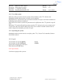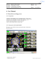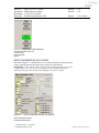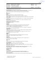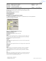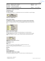
1
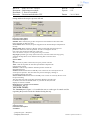
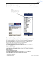
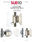
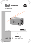
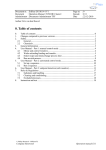
RWV nr. Document Hoofdstuk Beheerder : JerZij-2010-12-22-02V01 : Bedieningsvoorschrift : 0. Inhoudsopgave : Documentenbeheerder TFF Blad nr. : 0.0 Epcode : S31 Datum : 22-12-2010 Auteur: J.v.Zijl wagp 5.16 Inhoudsopgave Blad nr. / Aant. bladen 1. 2. 3. 4. 5. 6. 7. 8. Changes compared to previous versions ....................................................................... 1.1 Safety............................................................................................................................. 2.1 2.1 Safety of people ........................................................................................................ 2.1 2.2 Safety of the system .................................................................................................. 2.1 General information ...................................................................................................... 3.1 3.1 Veeco Nexus 800 ...................................................................................................... 3.1 3.1.1 Use of the system ........................................................................................... 3.2 3.1.2 Operating the system ..................................................................................... 3.2 3.1.3 Log in ............................................................................................................. 3.2 User Manual .................................................................................................................. 4.1 4.1 Run with an excisting process. ................................................................................. 4.1 4.1.1 Preparation ..................................................................................................... 4.1 4.1.2 Start proces with vented loadlock .................................................................. 4.1 4.1.3 Start proces with pumped loadlock. ............................................................... 4.5 Proces voorschrift.......................................................................................................... 5.1 5.1 Lot build .................................................................................................................... 5.1 5.2 Standaard configuration of the system ...................................................................... 5.2 5.3 Targets available ....................................................................................................... 5.2 5.4 Het maken van recepten ( level process engineer en hoger) ..................................... 5.3 5.4.1 Process Create Screen .................................................................................... 5.3 Rules & Regulations ..................................................................................................... 6.1 Instruction and test ........................................................................................................ 7.2 Gekwalificeerde personen lijst. ..................................................................................... 8.4 © Philips Research – MiPlaza/TL Company Restricted Filenaam: Operation manual S31 RWV nr. Document Hoofdstuk Beheerder : RWV-011-130-031/01.1 : Bedienings Voorschrift Veeco Nexus 800 :1. Wijzigingen t.o.v. de vorige versie : Documentenbeheerder TFF Blad nr. : 1.1 Epcode : S31 Datum : 26-11-2010 1. Changes compared to previous versions Date Page number 26-11-2010 New version number /01.1 Description First version with Document number . © Philips Research – MiPlaza/TL Company Restricted Filenaam: Operation manual S31 RWV nr. Document Hoofdstuk Beheerder : RWV-011-008-130/02 : Bedieningsvoorschrift : 2. Safety : Documentenbeheerder TFF Blad nr. : 2.1 Epcode : S31 Datum : 26-11-2010 2. Safety 2.1 Safety of people De Veeco Nexus 800 is voorzien van diverse interlocks om een veilige werksituatie te creëren. Toch zijn er bepaalde risico‟s aanwezig die iedereen die met de Veeco werkt goed moet weten. De risico‟s zijn: 1. Gassen: Argon , Zuurstof en stikstof , zijn niet giftig of gevaarlijk bij normaal gebruik, maar in afgesloten ruimten verdringen ze zuurstof 2. Elektra: Er zijn hoge spanningen aanwezig in het apparaat en de bijbehorende elektronica. Een elektrische shock kan de dood tot gevolg hebben. Kom in geen geval aan de elektrische bedrading, ook niet bij eenvoudige problemen. Waarschuw bij slecht of niet funktioneren de Apparaat eigenaar of EE&S. 3. Brandgevaar: Het brandgevaar is erg laag. In geval van brand, druk op een van de grote rode knoppen met als opschrift EMO of emergency off, en volg de algemene brand- en evacuatie aanwijzingen op. 4. Mechanische risico‟s: Buiten het load lock zijn alle mechanische bewegingen van onderdelen van het apparaat afgeschermd. Het openen en sluiten van de load lock stopt indien er een voorwerp gedetecteerd wordt in het detectie veld boven de loadlock. 5. Straling: Zichtbaar licht., n.v.t. a) Magnetisch veld. Het magnetisch veld varieert van 1 gauss op 50 cm afstand van de kamer tot 15 gauss in de buurt van de depositiekamers. Personen met een pacemaker is het verboden deze kamers te benaderen. 2.2 Safety of the system Druk op de noodstop „EMERGENCY OFF‟ als er gevaar is of dreigt. © Philips Research – MiPlaza/TL Company Restricted Filenaam: Operation manual S31 RWV nr. Document Hoofdstuk Beheerder : RWV-011-008-130/01.1 : Bedieningsvoorschrift : 3. Algemene werking : Documentenbeheerder TFF Blad nr. : 3.1 Epcode : S31 Datum : 26-11-2010 3. General information 3.1 Veeco Nexus 800 De VeecoNexus bestaat uit de volgende onderdelen: Twee load lock‟s waarmee de cassettes in machine geladen kunnen worden Een transferkamer met een robotarm, waarmee de depositie tafels getransporteerd kunnen worden. Drie proces kamers met hierin een shutter waarin de plakken geëtst worden (Pm2, Pm3 en pm5) 6 depositie kamers voor resp. ZNO-AL, Mo, AL, Ti, TiW, W De Veeco Nexus 800 is een single wafer machine waarin de plakken een voor een bewerkt kunnen worden in een of meerdere proceskamers. Nadat de cassette met de benodigde substraten in het load lock gezet is wordt het load lock afgepompt. Vanuit het load lock gaat de plak via de transfer kamer naar een van de proces kamers. Het sputteren van lagen gebeurd d.m.v. recepten en scheduless die in de machine aanwezig zijn. Als in de schedule vermeld staat dat de plakken voor depositie geëtst moeten worden, dan gaat de plak eerst naar kamer Pm2 of Pm5 , waar hij een sputterets krijgt. Daarna wordt het substraat naar de betreffende depositiekamer gebracht, waar het van een metaallaag wordt voorzien. Voor eventuele meerdere metaallagen wordt het proces herhaald. Hierbij wordt ditmaal de sputterets achterwege gelaten. Na depositie plaatst de robotarm het substraat weer terug in het load lock op zijn beginpositie in de cassette. Nadat alle plakken uit de cassette verwerkt zijn, wordt de load lock belucht en kan de cassette weer terug naar buiten. Het systeem wordt bediend m.b.v het toetsenbord aan de voorkant van het systeem. © Philips Research – MiPlaza/TL Company Restricted Filenaam: Operation manual S31 RWV nr. Document Hoofdstuk Beheerder : RWV-011-008-130/01.1 : Bedieningsvoorschrift : 3. Algemene werking : Documentenbeheerder TFF Blad nr. : 3.2 Epcode : S31 Datum : 26-11-2010 3.1.1 Use of the system Men kan wafers processen met het systeem als de machine op het CTC scherm staat. Standaard staat dit scherm aan de voorzijde van de machine. Mocht dit niet zo zijn kan men door op het het toetsenbord 2x op de scroll lock te drukken de bediening van het scherm veranderen Men komt in het selectie systeem en gaat men met de pijltjes naar het CTC gedeelte en geeft enter. Mocht het CTC gedeelte Rood kleuren dan staat het CTC scherm in de service ruimte actief. Je moet deze dan eerst inactief maken door in de service ruimte een ander scherm actief te maken volgens bovenstaande procedure. Bv pm1 3.1.2 Operating the system Standaard staat het systeem aan de voorzijde op het CTC ( Cluster Tool controller) Scherm In het Main scherm, 3.1.3 Log in Vul in achter de regel „Login ID. Vul in achter de regel „Password‟ (Dit word weergegeven in sterretjes) Druk daarna op de OK Knop. Veeco 123456 (foto login scherm) Je hebt nu toegang tot het systeem © Philips Research – MiPlaza/TL Company Restricted Filenaam: Operation manual S31 RWV nr. Document Hoofdstuk Beheerder : RWV-011-008-130/01.1 : Bedieningsvoorschrift : 4. Bedienings voorschrift : Documentenbeheerder TFF Blad nr. : 4.1 Epcode : S31 Datum : 26-11-2010 4. User Manual 4.1 Run with an excisting process. 4.1.1 Preparation Controleer of de machine en de te gebruiken targets “ Groen” zijn. Controleer of de bediening aan de voorzijde op het CTC scherm staat Gebruik de juiste schaaltjes ( zie Rules and regulations 5.1) Vul het electronisch logboek van het systeem in. Check of alle modules online ( groen) staan 4.1.2 Start proces with vented loadlock We gaan er van uit dat het scherm op het main menu scherm staat. Dit is dit scherm © Philips Research – MiPlaza/TL Company Restricted Filenaam: Operation manual S31 RWV nr. Document Hoofdstuk Beheerder : RWV-011-008-130/01.1 : Bedieningsvoorschrift : 4. Bedienings voorschrift : Documentenbeheerder TFF Blad nr. : 4.2 Epcode : S31 Datum : 26-11-2010 Ga met de muis naar het schedule CMR of CML scherm, afhankelijk welk Load lock gebruikt gaat worden. Klik op select, een lijst net beschikbare schedules komt in beeld. typ bv pm1 Al en er komt een lijst met daarin de processen die pm1 Al in de naam hebben. Selecteer het gewenste proces vb pm1 Al 1000nm - Druk op ok - Plaats de cassette in het load lock en trek de carriers terug in de achterste positie. - Sluit het loadlock - Klik op run in het schedule CMR of -CMR scherm, deze kleur groen (indien je dit niet doet gebeurd er niets !!!) Druk op load Dit schem verschijnt geef het lotnr in ddmmyy runnr © Philips Research – MiPlaza/TL Company Restricted Filenaam: Operation manual S31 RWV nr. Document Hoofdstuk Beheerder : RWV-011-008-130/01.1 : Bedieningsvoorschrift : 4. Bedienings voorschrift : Documentenbeheerder TFF Blad nr. : 4.3 Epcode : S31 Datum : 26-11-2010 druk op ok. De machine zal vragen of je de wafers wil mappen Druk op Yes Pas daarna wordt het loadlock afgepompt tot 5E-05 mBarr Check in het mapping scherm of de waferposities kloppen. Het proces wordt gestart. Nadat het proces klaar is, verschijnt het volgende scherm Druk op Yes Het loadlock wordt belucht tot 7.4 E2 Open het load lock en neem de cassette eruit De plakken kunen eruit worden genomen. Zet de lege cassette terug in het loadlock Pomp als volgt af: Klik in het main menu op loadlock Druk op Stop in het schedule CML of CMR gedeelte (De groene Run button wordt grijs en het loadlock scherm wordt actief) Druk op pumpdown. © Philips Research – MiPlaza/TL Company Restricted Filenaam: Operation manual S31 RWV nr. Document Hoofdstuk Beheerder : RWV-011-008-130/01.1 : Bedieningsvoorschrift : 4. Bedienings voorschrift : Documentenbeheerder TFF Blad nr. : 4.4 Epcode : S31 Datum : 26-11-2010 © Philips Research – MiPlaza/TL Company Restricted Filenaam: Operation manual S31 RWV nr. Document Hoofdstuk Beheerder : RWV-011-008-130/01.1 : Bedieningsvoorschrift : 4. Bedienings voorschrift : Documentenbeheerder TFF Blad nr. : 4.5 Epcode : S31 Datum : 26-11-2010 4.1.3 Start proces with pumped loadlock. We gaan er van uit dat het scherm op het main menu scherm staat. Dit is dit scherm Druk op de button Loadlock Selecteer bij CMR of CMR vent Het loadlock wordt belucht en je kan de deur openen, Plaats de te sputteren substraten in de Casette, Ga met de muis naar het schedule CMR of CML scherm, afhankelijk welk Load lock gebruikt gaat worden. Klik op select, een lijst net beschikbare schedules komt in beeld. typ bv pm1 Al en er komt een lijst met daarin de processen die pm1 Al in de naam hebben. Selecteer het gewenste proces vb pm1 Al 1000nm © Philips Research – MiPlaza/TL Company Restricted Filenaam: Operation manual S31 RWV nr. Document Hoofdstuk Beheerder : RWV-011-008-130/01.1 : Bedieningsvoorschrift : 4. Bedienings voorschrift : Documentenbeheerder TFF Blad nr. : 4.6 Epcode : S31 Datum : 26-11-2010 - Druk op ok - Plaats de cassette in het load lock en trek de carriers terug in de achterste positie. - Sluit het loadlock - Klik op run in het schedule CMR of -CMR scherm, deze kleurt groen (indien je dit niet doet gebeurd er niets !!!) Druk op load Dit schem verschijnt. geef het lotnr in ddmmyy runnr Druk op ok. De machine zal vragen of je de wafers wil mappen. © Philips Research – MiPlaza/TL Company Restricted Filenaam: Operation manual S31 RWV nr. Document Hoofdstuk Beheerder : RWV-011-008-130/01.1 : Bedieningsvoorschrift : 4. Bedienings voorschrift : Documentenbeheerder TFF Blad nr. : 4.7 Epcode : S31 Datum : 26-11-2010 Druk op Yes. Pas daarna wordt het loadlock afgepompt tot 5E-05 mBarr Check in het mapping scherm of de waferposities kloppen. ( aantal wafers en posities ) Het proces wordt gestart. Nadat het proces klaar is, verschijnt het volgende scherm Druk op Yes Het loadlock wordt belucht tot 7.4 E2 Open het load lock en neem de cassette eruit De plakken kunen eruit worden genomen. © Philips Research – MiPlaza/TL Company Restricted Filenaam: Operation manual S31 RWV nr. Document Hoofdstuk Beheerder : RWV-011-008-130/01.1 : Bedieningsvoorschrift : 4. Bedienings voorschrift : Documentenbeheerder TFF Blad nr. : 4.8 Epcode : S31 Datum : 26-11-2010 Indien er nog een lot gestart moet worden Vul dan het Schedule CMR of Schedule CML in en laad een nieuwe cassette, Wil je geen proces meer starten ,zet dan de lege casette in het load lock. Pomp als volgt af: Klik in het main menu op loadlock Druk op Stop in het schedule CML of CMR gedeelte (De groene Run button wordt grijs en het loadlock scherm wordt actief) Druk op pumpdown. © Philips Research – MiPlaza/TL Company Restricted Filenaam: Operation manual S31 RWV nr. Document Hoofdstuk Beheerder : RWV-011-031-130/01.1 : Bedieningsvoorschrift : 5. Proces voorschrift : Documentenbeheerder TFF Blad nr. : 5.1 Epcode : S31 Datum : 26-11-2010 5. Proces voorschrift 5.1 Lot build Indien er met vaste schedules gewerkt wordt zijn er vaste plaatsen in de Schedule voor het insputteren van de te gebruiken targets. Dit is nodig om het zogenaamde eerste plak effect te vermijden. Een voorbeeld volgt hieronder Lot pm5 TiW 20 nm Pm 6 W 5000 nm Conditionerings plakken zitten altijd onder in het lot met de volgorde van de systeem configuratie mee. De slot nummering is van onder naar boven. Slot # Slot 3 t/m 10 Slot 2 Slot 1 Sequence Pm5 TiW 20nm Pm6 W 5000 nm Pm6 W Condi Pm5 TiW condi Te gebruiken schaaltjes Gebruik Ti / W Schaaltje Gebruik Ti / W Schaaltje Gebruik Ti / W schaaltje © Philips Research – MiPlaza/TL Company Restricted Filenaam: Operation manual S31 RWV nr. Document Hoofdstuk Beheerder : RWV-011-031-130/01.1 : Bedieningsvoorschrift : 5. Proces voorschrift : Documentenbeheerder TFF Blad nr. : 5.2 Epcode : S31 Datum : 26-11-2010 5.2 Standaard configuration of the system Normally this is the standard configuration of targets in the system. Pm1 ZNO-AL 2% Pm2 Mo Pm3 Al / ALN ( geen Al2O3 processing) pm4 Al Pm5 Ti10W90 Pm6 W 5.3 Targets available On request we wil place the next matrials in the system. Additional time will be charged to the customer (4 Hours / target ) Pm1 .. Pm2 MoCr3, MoNb2%, Ni pm3 Pm4 Ti, ALNd2%, AlCu1%, AlSi1%, Cu Pm5 C, Ti5W95 Pm6 .. Op aanvraag kunnen andere targets besteld worden via de systeem eigenaar © Philips Research – MiPlaza/TL Company Restricted Filenaam: Operation manual S31 RWV nr. Document Hoofdstuk Beheerder : RWV-011-031-130/01.1 : Bedieningsvoorschrift : 5. Proces voorschrift : Documentenbeheerder TFF Blad nr. : 5.3 Epcode : S31 Datum : 26-11-2010 5.4 Het maken van recepten ( level process engineer en hoger) 5.4.1 Process Create Screen Introductie: Only users with a privilege level of Process Engineer or above can access this screen. Using the Process Create screen (Figure 3–1), the user creates steps that detail system operating parameters and inserts them into a sequence called a process. Figure 3–1. Process Create Screen Each step within the process details all the information needed by the system to perform the operation. Once defined, steps are inserted into a process. Each process is assigned a unique name by the user and is permanently stored on the system‟s hard drive, allowing the user access and editing functions. The user also has the ability to select any set of steps and create any number of new processes for specific applications. Once a new process is created, it is also permanently stored, and can be run by an operator through simple menu selection. CAUTION—Because the CTC hard drive stores process, configurations, and INI files, it is important to back up these files. AREAS OF THE PROCESS CONTROL SCREEN The Process Create screen consists of the Main Menu, Process Area Panel, UserDefined Parameters and Values Panels, Recipe Management Panel, Process Create © Philips Research – MiPlaza/TL Company Restricted Filenaam: Operation manual S31 RWV nr. Document Hoofdstuk Beheerder : RWV-011-031-130/01.1 : Bedieningsvoorschrift : 5. Proces voorschrift : Documentenbeheerder TFF Blad nr. : 5.4 Epcode : S31 Datum : 26-11-2010 Panel, and the Events and Alarms Panel. Figure 3–2. Areas of the Process Create Screen Main Menu Clicking Main Menu (Figure 3–2) displays the Main Menu dialog (Figure 2–8). Using this dialog, the user can sign on and off the screen, and navigate to the other screens. For additional information, see Main Menu on page 2–7. Events and Alarms Panel The Events and Alarms panel (Figure 3–2) displays connection status, events and alarms, events log, and enables the user to abort a process. For additional information, see EVENTS AND ALARMS PANEL on page 2–14. Process Create Panel The Process Create panel (Figure 3–3) contains two subpanels: Process List, and Step List. The functionality these panels provide is described in the following tables. © Philips Research – MiPlaza/TL Company Restricted Filenaam: Operation manual S31 RWV nr. Document Hoofdstuk Beheerder : RWV-011-031-130/01.1 : Bedieningsvoorschrift : 5. Proces voorschrift : Documentenbeheerder TFF Blad nr. : 5.5 Epcode : S31 Datum : 26-11-2010 Figure 3–3. Process Create Panel Process List Panel Item Description Load Loads a previously created process. Save Saves the current process to the process list. Save As Saves the current process to the process list with a user-specified name. New Creates a new process list. Delete Deletes the current process from the process list. Quick View View an entire process in a spread sheet format. Changes cannot be made to the recipe. Quick Copy Copies entire process list to an external source such as a floppy disk. Step List Panel Item Description Load Loads a previously created step to the step list. Save Saves the current step to the step list. Save As Saves the current step to the step list with a user-specified name. New Creates a new process step. Delete Deletes the current step from the step list. Process List Panel Step List Panel Process Create Screen 3–4 TC10045 Rev. A © Philips Research – MiPlaza/TL Company Restricted Filenaam: Operation manual S31 RWV nr. Document Hoofdstuk Beheerder : RWV-011-031-130/01.1 : Bedieningsvoorschrift : 5. Proces voorschrift : Documentenbeheerder TFF Blad nr. : 5.6 Epcode : S31 Datum : 26-11-2010 Process Area Panel The Process Area panel (Figure 3–4) displays the name of the process and lists the steps of the process. It also enables the user to add or delete steps from the process. When you click a step in the step list, a box displays around the step and the step name also displays in the area above the process name. Figure 3–4. Process Area Panel Item Description Insert Click to insert a step. Delete Click to delete a step. © Philips Research – MiPlaza/TL Company Restricted Filenaam: Operation manual S31 RWV nr. Document Hoofdstuk Beheerder : RWV-011-031-130/01.1 : Bedieningsvoorschrift : 5. Proces voorschrift : Documentenbeheerder TFF Blad nr. : 5.7 Epcode : S31 Datum : 26-11-2010 User-Defined Parameters and Values Panels These panels display the parameter values of the step. They also enable the user set the parameters for new steps or change the parameters of an existing step. A description of each panel is given on the following pages. User-Defined Parameters and Values Panels Figure 3–5. User-Defined Parameters and Values Panels PROCESS MODULE BUTTONS The Process Module buttons (Figure 3–6) enable the user to display the process create screen for the module they want to create a new step or process, or revise an existing step or process. Before creating or revising a step or process, the user must select the desired process module. © Philips Research – MiPlaza/TL Company Restricted Filenaam: Operation manual S31 RWV nr. Document Hoofdstuk Beheerder : RWV-011-031-130/01.1 : Bedieningsvoorschrift : 5. Proces voorschrift : Documentenbeheerder TFF Blad nr. : 5.8 Epcode : S31 Datum : 26-11-2010 Figure 3–6. Process Module Buttons User-Defined Parameters and Values Panels Process Module Buttons DEPO PARAMETERS (DC) PANEL This panel (Figure 3–7) enables the user to set the parameters for the deposition source, rotation speed of the target, and gas flow for each channel. WARNING—aUse caution when setting the pulse mode parameters as certain configurations can cause excessive arcing inside the chamber and lead to major particle generation and possible damage to the power supply. Figure 3–7. Depo Parameters Panels–DC and RF Depo Parameters Panel Parameter Description © Philips Research – MiPlaza/TL Company Restricted Filenaam: Operation manual S31 RWV nr. Document Hoofdstuk Beheerder : RWV-011-031-130/01.1 : Bedieningsvoorschrift : 5. Proces voorschrift : Documentenbeheerder TFF Blad nr. : 5.9 Epcode : S31 Datum : 26-11-2010 Use Source When checked, enables the source. Control Mode Sets the mode of operation (Continuous, Timed, Joules, KiloJoules, or Sequence) for the power supply. The user selects the control mode by clicking the drop-down arrow and selecting the mode of operation from the list. Regulation Mode Sets the output (Power or Voltage) of the power supply. Ramp Time Sets the length of time for the power supply to ramp up. Power (Watts) Enabled only when regulation mode is set to Power. Sets the output of the power supply. Voltage (V) Enabled only when regulation mode is set to Voltage. Sets the output of the power supply. Energy Enabled only when Control Mode is set to Joules or KiloJoules. Sets the output of the DC power supply. NEXUS PVD–1 Systems User Manual TC10045 Rev. A 3–7 Sequence Number Enabled only when Control Mode is set to Sequence. Sets the power supply to operate using one of the programmed sequences. The user selects the sequence number by clicking the up or down arrow. Note: Sequences are preprogrammed. Refer to the Power Supply User Manual for information on how to program sequences. Pulsed Mode Enable When selected, it enables a reversing voltage on the power supply output. it is typically used for arc control in the system. Note: Pulsing parameters are controlled by the configuration software and are downloaded to the generator on startup. Frequency (kHz) Enables the user to set the frequency at which the generator reverses the polarity of its voltage output to a positive voltage. Pulse Rev. Time (μS) Enables the user to set the length of time that the positive voltage exists on the output. Time is displayed in μS. Duty Cycle (%) Enables the user to to set the calculated duty cycle for the percentage of time that a positive voltage is on the generator output. Arc Counting Enable When selected, it enables the arc counting feature. Max Count Enables the user to set the number of arcs that can occur before an alarm is generated for a process step. Reset Delay Enables the user to set the time between the detection of an arc, which causes the generator output to be disabled, and the reenabling of the generator output. Target Rotation Rotation Speed (RPM) Enables the user to set the rotation speed of the target. the change the speed, the user can enter the value directly or use the up and down arrows. Process Gas Values 1, 2, 3, 4 Enables the user to set the gas flow for each channel. The flow range levels © Philips Research – MiPlaza/TL Company Restricted Filenaam: Operation manual S31 RWV nr. Document Hoofdstuk Beheerder : RWV-011-031-130/01.1 : Bedieningsvoorschrift : 5. Proces voorschrift : Documentenbeheerder TFF Blad nr. : 5.10 Epcode : S31 Datum : 26-11-2010 depend on the mass flow controllers installed for each channel. To change the value of a gas channel, the user enters the value in the field next to the desired channel. Depo Parameters Panel (Continued) Parameter Description Process Create Screen 3–8 TC10045 Rev. A BIAS\ETCH PARAMETERS PANEL The Bias\Etch Parameters panel (Figure 3–8) enables the user to set the parameters for the power supply to the chuck. Figure 3–8. Bias\Etch Parameters Panel Bias\Etch Parameters Panel Parameter Description Use Source When checked, enables the source. Regulation mode Sets the mode of operation (Power or Voltage) for the power supply. The user selects the control mode by selecting the drop-down arrow and then selecting the mode of operation from the list. Bias Power (Watts) Enabled only when regulation mode is set to Power. Sets the output of the power supply. Bias Voltage (V) Enabled only when regulation mode is set to Voltage. Sets the output of the power supply. Matching Network Mode Enables the user to use stored preset (Automatic) values or to manually control (Manual) the capacitors. The user selects the control mode by selecting the drop-down arrow and then selecting Automatic or Manual from the list. C1 C2 Enabled only when Matching Network Mode is set to Manual. Enables the user to set the value for capacitors 1 and 2. To enter a value, the user can enter the value or use the up and down arrows. © Philips Research – MiPlaza/TL Company Restricted Filenaam: Operation manual S31 RWV nr. Document Hoofdstuk Beheerder : RWV-011-031-130/01.1 : Bedieningsvoorschrift : 5. Proces voorschrift : Documentenbeheerder TFF Blad nr. : 5.11 Epcode : S31 Datum : 26-11-2010 NEXUS PVD–1 Systems User Manual TC10045 Rev. A 3–9 STAGE PANEL The Stage panel (Figure 3–9) enables the user to move the chuck to a specific height. Figure 3–9. Stage Panel SHUTTER PANEL The Shutter panel (Figure 3–10) enables the user to set the position of the shutter (Open or Close) at 3 different points (At Start, At Stabilize, and At End) during the process. The shutter position is set by selecting Open or Close from the drop-down lists. Figure 3–10. Shutter Panel BACK SIDE GAS PANEL Displays only on process modules using back side gas to cool the substrate. The Back side gas panel (Figure 3–11) enables the user to set the pressure setpoint for the back side gas. To enter a value, select the current value and enter the new value. Figure 3–11. Back Side Gas Panel Stage Panel Parameter Description Stage Height (mm) Used to move the chuck to a specific height. To change the height, the user enters a new value or uses the up and down arrows. Note: The value displayed represents the distance the chuck is from 0 (transfer) position. Drop-Down Lists NOTE Process Create Screen 3–10 TC10045 Rev. A PROCESS CONTROL PANEL The Process Control panel (Figure 3–12) allows the user to define the process © Philips Research – MiPlaza/TL Company Restricted Filenaam: Operation manual S31 RWV nr. Document Hoofdstuk Beheerder : RWV-011-031-130/01.1 : Bedieningsvoorschrift : 5. Proces voorschrift : Documentenbeheerder TFF Blad nr. : 5.12 Epcode : S31 Datum : 26-11-2010 timing and how the step in a process will end. Figure 3–12. Process Control Panel Process Control Panel Parameter Description Stabilize When selected, the gas flow and pressure will stabilize to their final value before the timer for that step starts. Power Down When selected, all power supplies will be turned off upon completion of the step. Data Tracing When selected, a data file will be created with all relevant process parameters at the time interval specified. To enter or change the interval time, select the current time and enter a new time. Note: The data is used for reviewing historical process data. Step Type Specifies type of step (Start or Process). The user selects the step type by selecting the drop-down arrow and then selecting Start or Process from the list. Process Ends By Specifies how (by Time or Pressure) a step in a process will end. Time - ends the step after the total time specified has elapsed in the running of the process. Pressure - ends the step when the chamber pressure reaches the designated pressure. Pressure Enabled when Process Ends By is set to Pressure. It is used by the user to set the process pressure. The user enters the pressure setting by clicking in the field and entering the value. Process Time Enabled when Process Ends By is set to Time. It is used by the user to set the process timing. The user enters the time using either the Hours, Minutes, Seconds, and ms fields or the Time In Seconds field. As you enter the time, the time displays is both sets of fields. NEXUS PVD–1 Systems User Manual TC10045 Rev. A 3–11 VACUUM PANEL The Vacuum panel (Figure 3–13) enables the user to set the type of control used for regulating the pressure inside the chamber during the step. Figure 3–13. Vacuum Panel Vacuum Panel Parameter Description Use HiVac © Philips Research – MiPlaza/TL Company Restricted Filenaam: Operation manual S31 RWV nr. Document Hoofdstuk Beheerder : RWV-011-031-130/01.1 : Bedieningsvoorschrift : 5. Proces voorschrift : Documentenbeheerder TFF Blad nr. : 5.13 Epcode : S31 Datum : 26-11-2010 Pressure Control Mode The user selects the control mode (Absolute, DownStream, DownStreamFixed, or Position) by clicking the drop-down arrow and selecting the control mode from the listing. Absolute DownStream - Uses a fixed gas flow (set in the Depo Parameters panel) and regulates the pressure in the chamber by actively controlling the position of the cryo pump gate valve. DownStreamFixed Position - The position of the cryo pump gate valve is set to a specific percentage (%) open, thereby fixing the pumping speed of the cryo pump. There is no active pressure regulation in this mode. Pressure Setpoint (mTorr) Enabled when pressure control mode is set to Downstream. Sets the pressure in the chamber for the step. Position setpoint (%) Enabled when pressure control mode is set to Absolute, DownStreamFixed or Position. Sets percentage (%) open of the cryo pump gate valve for the step. Process Create Screen 3–12 TC10045 Rev. A Recipe Management Panel The Recipe Management panel (Figure 3–14) displays information on when the process was created and last edited. Figure 3–14. Recipe Management Panel Recipe Management Panel Parameter Description Created By: Identifies who created the recipe. The information in this field is automatically created when the user clicks Save. Create Date: Identifies the date the recipe was created. The information in this field is automatically created when the user clicks Save. Last Edit By: Identifies the person who last edited the the recipe. The information in this field is automatically created when the user clicks Save. © Philips Research – MiPlaza/TL Company Restricted Filenaam: Operation manual S31 RWV nr. Document Hoofdstuk Beheerder : RWV-011-031-130/01.1 : Bedieningsvoorschrift : 5. Proces voorschrift : Documentenbeheerder TFF Blad nr. : 5.14 Epcode : S31 Datum : 26-11-2010 Last Edit Date: Identifies the date the recipe was last edited. The information in this field is automatically created when the user clicks Save. NEXUS PVD–1 Systems User Manual TC10045 Rev. A 3–13 WORKING WITH THE PROCESS SCREEN Creating a Process - Overview Shown below (Figure 3–15) are the functions performed when creating steps and inserting them into a process. Figure 3–15. Creating a Process How to Create a New Process A process consists of steps that define how a substrate is to be proceseed. the following steps describe how to create a new process. 1. Click the process module button (Figure 3–6) for the process module you want to create the process. 2. Click New in the Process List panel (Figure 3–3). 3. Enter the file name of the process in the dialog that appears. 4. Click Save. An extension of Prc is automatically attached to the process name. Process List [Process Steps] Step_1=warm-up Step_2= Step_3= Step_4= Step_5= ... Step_24= (max. 20 0 steps) Process Step List 2. Name the step, e.g., warm-up. 3. Define the contents of the step by entering the desired values for the beam, gas, control, shutter, target, and fixture parameters. 4. After the values are entered into the step, - name a step list - insert step into step list Repeat these steps, for additional process steps. TO CREATE A PROCESS STEP After all the steps are defined and inserted into the step list, the process can be run on the system. 1. Select the PM designator. Process Create Screen 3–14 TC10045 Rev. A How to Create a Step 1. Click the process module button (Figure 3–6) for the process module you want to create the step. © Philips Research – MiPlaza/TL Company Restricted Filenaam: Operation manual S31 RWV nr. Document Hoofdstuk Beheerder : RWV-011-031-130/01.1 : Bedieningsvoorschrift : 5. Proces voorschrift : Documentenbeheerder TFF Blad nr. : 5.15 Epcode : S31 Datum : 26-11-2010 2. Click New in the Step List panel (Figure 3–3). 3. Enter the file name of the step in the dialog that appears. 4. Click Save. An extension of Stp is automatically attached to the step name. 5. Enter the parameters for the step. See User-Defined Parameters and Values Panels on page 3–5. 6. Click Save or Save As. Clicking Save As allows you save the step with a new name. Adding Previously Created Steps to a Process Step List 1. Click the process module button (Figure 3–6) for the process module you want to add the step. 2. Click Load in the Process List panel (Figure 3–3). The Process List screen appears (Figure 3–16). It lists all the previously created process lists for the module. Figure 3–16. Process List Screen 3. Select the desired process list file name from the list and click OK. Note that double-clicking the file name automatically selects the process list without having to click OK. You can also filter the list by using Quick Search. Just type the name of the desired file in the Quick Search field and Quick Search will display only those files that match your input. Then, select the desired file as described above. 4. Click Insert (Figure 3–17) in the Process Area panel. A screen appears listing all the previously created steps to choose from. Quick Search Field Enter the name of the process list, and as you type, Quick Search will display only those files that match your input. NEXUS PVD–1 Systems User Manual © Philips Research – MiPlaza/TL Company Restricted Filenaam: Operation manual S31 RWV nr. Document Hoofdstuk Beheerder : RWV-011-031-130/01.1 : Bedieningsvoorschrift : 5. Proces voorschrift : Documentenbeheerder TFF Blad nr. : 5.16 Epcode : S31 Datum : 26-11-2010 Quick Search Field Enter the name of the process list, and as you type, Quick Search will display only those files that match your input Figure 3–17. Adding Steps to the Process List 5. Select the desired step file name from the list and click OK. Note that doubleclicking the file name automatically selects the file without having to click OK. You can also filter the list by using Quick Search. Just type the name of the desired file in the Quick Search field and Quick Search will display only those files that match your input. Then, select the desired file as described above. 6. Repeat this process until you are done creating the list. 7. Click Save or Save As in the Process List panel (Figure 3–3),to save the process list. Clicking Save As allows you save the list with a new name. How to Edit Steps 1. Click Load in the Step List panel (Figure 3–3). A screen appears that lists all the previously created steps (Figure 3–17). 2. Select the desired step by double-clicking on it. The screen displays the parameters for the selected step. 3. Edit the parameters as necessary. 4. Click Save or Save As in the Step List panel (Figure 3–3), to save the step. Clicking Save Step As allows you save the step with a new name. © Philips Research – MiPlaza/TL Company Restricted Filenaam: Operation manual S31 RWV nr. Document Hoofdstuk Beheerder : RWV-011-031-130/01.1 : Bedieningsvoorschrift : 5. Proces voorschrift : Documentenbeheerder TFF Blad nr. : 5.17 Epcode : S31 Datum : 26-11-2010 Quick Search Field Enter the name of the process list, and as you type, Quick Search will display only those files that match your input. Process Area Panel Chapter 4 Process Control Screen INTRODUCTION All users are able to display the Process Control screen. However, access to sub-menus and operations depend on assigned privilege levels. The Process Control screen (Figure 4–1) manages the operation of the load lock cassette elevator and robot arm, enables the user to select and run a process, and displays readbacks for the sources and wafer status. It is made up of four areas: Menu Bar, Status Panels, Graphical Display, and Events and Alarm Panel. Figure 4–1. Process Control Screen For information on the Events and Alarms Panel, see EVENTS AND ALARMS PANEL on page 2–14. NOTE Graphical Display Events and Alarms Panel Menu Bar Status Panels Process Control Screen 4–2 TC10045 Rev. A MENU BAR The menu bar (Figure 4–2) provides access to the Main Menu, PM Buttons, Load Lock, View Data Log, and Process Parameters and Process Times dialogs. Figure 4–2. Menu Bar–Process Control Screen Main Menu Clicking Main Menu (Figure 4–2), displays the Main Menu dialog (Figure 4–3). Using the Main Menu, the user can sign on and off the system and navigate to the other screens that make up the software. For additional information, see Main Menu on page 2–7. Figure 4–3. Main Menu PM Buttons The PM buttons (Figure 4–2) display the PM panel for the process module. Clicking the PM button for the PVD–1 displays the PM panel shown in Figure 4–4. This panel enables the user is able to control the processing of substrates in the process module and put the process module on or off line. Figure 4–4. PM Panel—PVD–1 Module PM buttons NEXUS PVD–1 Systems User Manual TC10045 Rev. A 4–3 Load Lock Clicking Load Lock on the menu bar displays the Load Lock panel (Figure 4–5). Using this panel, the user is able to control various load lock operations. Figure 4–5 shows a Load Lock panel for a tool with 2 load locks. If tool has only 1 load lock, © Philips Research – MiPlaza/TL Company Restricted Filenaam: Operation manual S31 RWV nr. Document Hoofdstuk Beheerder : RWV-011-031-130/01.1 : Bedieningsvoorschrift : 5. Proces voorschrift : Documentenbeheerder TFF Blad nr. : 5.18 Epcode : S31 Datum : 26-11-2010 the LLB portion of panel is grayed out. Figure 4–5. Load Lock Panel—Tool with 2 Load Locks PM Panel Item Description Abort When Abort is selected, the following occurs: •Current process stops running •Time stops counting •Plasma turns off •Process gas turns off •System goes off line End Current Step When selected, ends the current step and immediately advances to the next step in the process. Unload When selected, initiates an unload sequence. A log file is copied to the CTC. On Line When selected, places the process module on line. Off Line When selected, places the process module off line NOTE Process Control Screen 4–4 TC10045 Rev. A View Data Log Clicking View Data Log (Figure 4–2) displays the Data Log File Selector (Figure 4–6). The Data Log File Selector displays the file location of data logs. Double-click the desired log and it will appear. To close and return to the program, click on the close icon. Every day that the tool is used to process substrates, a new sub-directory is created with the current date. In the sub-directory are the RunNo_ directories for runs processed that day. Note that the RunNo_ directories are named according to the run number and the time (military time) that the first wafer starts processing. Each time another pallet is run, the run number, RunNo_, is incremented. To view the log files for wafers run during a particular run: double-click the desired RunNo_ directory to display the log files for wafers processed in that run, and then double-click the.txt file for the wafer. Figure 4–6. View Data Log Load Lock Panel Item Description Load Cassette Automatically pumps down the load lock chamber, maps the cassette, and prepares the load lock for a schedule to process substrates. Vent LoadLock Automatically vent the load lock chamber by closing the turbo gate valve (if installed), shutting off the turbo pump, closing the turbo foreline valve (if installed), and opening the vent valve. Pump Down Automatically pumps down the load lock using the roughing pump and, if installed, the turbo or cryo pump. Map Maps the cassette. An automatic sequence maps the cassette and prepares the load lock for a schedule to process substrates. Mapping assigns the status of unprocessed to all substrates in the cassette. Home Brings the elevator to its home position or reference point. All other positions are determined by referring to the home position. Sub-directory RunNo_ directory © Philips Research – MiPlaza/TL Company Restricted Filenaam: Operation manual S31 RWV nr. Document Hoofdstuk Beheerder : RWV-011-031-130/01.1 : Bedieningsvoorschrift : 5. Proces voorschrift : Documentenbeheerder TFF Blad nr. : 5.19 Epcode : S31 Datum : 26-11-2010 Log files for wafers processed Run number Time wafer started processing Time first wafer started Wafer number processing NEXUS PVD–1 Systems User Manual TC10045 Rev. A 4–5 View Process Parameters Clicking View Process Parameters displays the process parameters panel (Figure 4–7). This panel enables the user to view the real-time parameters of the currently running process for any process module by clicking the desired process module. Figure 4–7. Process Parameters Panel—PVD–1 Module View Process Times Clicking View Process Times displays the Wafer Processed Times panel (Figure 4–8). This panel enables the user to view the wafer process times for either loadlock. Figure 4–8. Wafer Processed Times Panel Process Control Screen 4–6 TC10045 Rev. A GRAPHICAL DISPLAY General Information The graphical display consists of an animated screen that graphically displays the progress of substrate processing and status panels that display the status of the process and enable the user to perform various functions. Figure 4–9. Graphical Display–Process Control Screen Indicators During system operation the screen will display various operations, options, and processes. Their status is indicated by the following colors: Status Panels Animated Screen Color Status Panels, Buttons, and Indicators Green Denotes a valve is open or an ON state for a button. Gray Denotes a valve is closed, an OFF state for a button, or an option is disabled. Red Denotes an error state for the action being performed. Yellow Denotes an intermediate state for a device being actuated. Blue Gate or ISO valve is closed. NEXUS PVD–1 Systems User Manual TC10045 Rev. A 4–7 Status Panels OPERATOR PANEL The operator panel (Figure 4–10) displays the current user. Figure 4–10. Operator Panel SCHEDULE/RUN PANELS The schedule/run panels (Figure 4–11) enable the user to select a previously created schedule and run it. The name of the process selected will display in the window. Schedule LLB displays only if tool has 2 load locks. © Philips Research – MiPlaza/TL Company Restricted Filenaam: Operation manual S31 RWV nr. Document Hoofdstuk Beheerder : RWV-011-031-130/01.1 : Bedieningsvoorschrift : 5. Proces voorschrift : Documentenbeheerder TFF Blad nr. : 5.20 Epcode : S31 Datum : 26-11-2010 Figure 4–11. Schedule/Run Panel Substrate in Chamber Green Process completed successfully. Yellow Substrate is partially processed. Blue Process has not started. Red An error has occurred. Color Status Schedule/Run Panels Item Description Process Display Displays the name of the process being run. Select Enables the user to select the schedule to run. To select a schedule, click Select and choose a schedule from the list that appears. Run Click Run to run the schedule. NOTE Process Display Process Display Process Control Screen 4–8 TC10045 Rev. A PROCESS MODULE PANEL The Process Module panel (Figure 4–12) enables the user to change the status (On Line or Off Line) view the status of the process module. For every process module on the tool, there is a process module panel. Only 3 process module panels can be displayed on the screen. To view other process module panels, click the PM selector to display the drop down list and and select the process module. Figure 4–12. Process Control Panel - Process Control Panel Item Description On/Off Line Button and Indicator This is both an indicator and button. It displays the status of the process module and also enables the user to change the status of the process module by clicking on it. When the process module is: •On Line - the words On Line display and the indicator is green. •Off Line - the words Off Line display and the indicator is yellow. Note: A module must be online for communication to occur between the PM and the CTC. If a module is offline, it cannot accept or return a substrate. Entering a process module screen during active processing will cause a module to go offline. To put the module back online, you must do this manually by clicking the communication indicator (Figure 2–18) for the module. Fixture Displays the status of the chuck. Motion Initialized - when the display is green, the chuck is at the transfer (0) position, the shutter is in the open position and the PM is ready to receive or release a substrate. Locked - when display is green, motion on the PM is suspended (locked) while the isolation valve is open. Lift Table Position - displays the height of the chuck from the transfer (0) position. Wafer ID Displays the wafer ID for the wafer currently being processed. NOTE On/Off Line Button and Indicator Step No. Field PM Selector NEXUS PVD–1 Systems User Manual © Philips Research – MiPlaza/TL Company Restricted Filenaam: Operation manual S31 RWV nr. Document Hoofdstuk Beheerder : RWV-011-031-130/01.1 : Bedieningsvoorschrift : 5. Proces voorschrift : Documentenbeheerder TFF Blad nr. : 5.21 Epcode : S31 Datum : 26-11-2010 TC10045 Rev. A 4–9 Process Displays the name of the currently running process and the status of the process in the Process Status field. The field will display the following: Idle, Cancelled, Running, Aborted, Stopping, Paused, or Pending. Elapsed Displays the time elapsed since the start of the current step. Remaining Displays the time left to complete the current step. Main Step Displays the name of the currently running step, or the name of the step that was being run when the process was stopped. It also displays the running step of the overall process (3 of 56, 2 of 23, etc.) in the Step No. field. Status Displays the status of the process module. Not Ready - A transfer cannot occur at this time. Ready To Load - A wafer is ready to be loaded. Motion is initialized, and the vacuum levels are good. Ready To Run - A wafer is loaded and a process is ready to run. Waiting To Run - A partially processed (yellow) wafer is waiting to be run. The Allow Partial Wafers To Run option, on the Management Options tab, must be selected for processing to continue from this state. Running - A process is currently running. Ready to Unload - The process is complete. The wafer is ready to be moved back to the Loadlock. Test Schedule Complete - The CTC is checking that all schedule phases have been completed for this wafer. Target Usage In KWH Displays the cumulative power dissipated on the tarrget. Source Displays the status of various source interlocks. Rotation - When green, indicates that the cathode is rotating. Gas - When green, indicates gas is flowing in the chamber. Depo - When green, indicates all deposition power supply interlocks are made. Etch - When green, indicates all etch power supply interlocks are made. Process Control Panel (Continued) Item Description Process Control Screen 4–10 TC10045 Rev. A SUBSTRATE STATUS PANEL The substrate status panel (Figure 4–13), one for each loadlock, displays the status of each slot and substrate by color. • When Home is highlighted, it indicates that the elevator is all the way up and cannot load or unload any substrates. • When a slot number is highlighted in blue, it indicates that the slot is aligned with the opening of the isolation valve. The arm is ready to pick up a substrate from that slot. • When slot status indicator is blinking, it indicates that the processing of the substrate was interrupted. Figure 4–13. Substrate Status Panel Substrate Status Color Code Color of Slot Status Indicator Description Black No substrate in the slot. Blue Substrate is not processed. Green Substrate is processed. Yellow Substrate is being processed. © Philips Research – MiPlaza/TL Company Restricted Filenaam: Operation manual S31 RWV nr. Document Hoofdstuk Beheerder : RWV-011-031-130/01.1 : Bedieningsvoorschrift : 5. Proces voorschrift : Documentenbeheerder TFF Blad nr. : 5.22 Epcode : S31 Datum : 26-11-2010 Red An error has occurred. NOTE Slot Number Slot Status Indicator NEXUS PVD–1 Systems User Manual TC10045 Rev. A 4–11 VACUUM PRESSURE PANELS On the process control screen there are panels (Figure 4–14) that display the pressure levels for the process module and FE loader and identify the pressure gauge reading (pirani, manometer, or ion). Figure 4–14. Vacuum Pressure Panels The trend bar indicates the amount of pressure change over time. Green bars indicate that the pressure is decreasing, while red bars indicate that the pressure is rising. LOAD/READY PANEL The Load/Ready panel (Figure 4–15) allows the user to prepare a load lock for processing substrates into the selected process module and it also provides load lock status information. Figure 4–15. Load/Ready Panel Load/Ready Panel Item Description Load When clicked, the load lock is automatically pumped down and mapped. Ready Provides load lock status by color. Yellow - The load lock chamber is either being pumped down, vented, or the cassette is being mapped. Green - The load lock chamber is pumped down and the cassette is mapped. Black - The load lock chamber is not ready. Red - An error has occurred. Indicates Active Pressure Gauge Reading: P = Pirani M = Manometer I = Ion Clicking the drop-down arrow expands the panel to display the readings of all the gauges (active and inactive). Trend Bar Process Control Screen 4–12 TC10045 Rev. A WAFER ALLOCATION PANEL The Wafer Allocation panel (Figure 4–16) enables the user to override the default behavior of the system software. The panel displays whenever you double-click any of the areas shown. To move a substrate, there must be no schedules running or the schedules must be paused. Figure 4–16. Wafer Allocation Panel Wafer Allocation Panel Item Description Location Specifies the location of the substrate. Select from the drop-down list. Slot # Specifies the slot number of the substrate. Select from the drop-down list. Wafer ID Specifies the substrate ID number. Select from the drop-down list. © Philips Research – MiPlaza/TL Company Restricted Filenaam: Operation manual S31 RWV nr. Document Hoofdstuk Beheerder : RWV-011-031-130/01.1 : Bedieningsvoorschrift : 5. Proces voorschrift : Documentenbeheerder TFF Blad nr. : 5.23 Epcode : S31 Datum : 26-11-2010 Status Displays the status of the wafer and enables the user to change the status of the wafer by selecting the new status from the drop-down list. Fault Tolerance Status Not supported. Add Adds a substrate. NOTE Wafer allocation panel Double-click on any slot. Double-click on any of these areas or wherever a wafer is shown. NEXUS PVD–1 Systems User Manual TC10045 Rev. A 4–13 Clear Clears the substrate Close Closes the wafer allocation panel. Clear All Clears all substrates. Wafer Allocation Panel (Continued) Item Description Process Control Screen 4–14 TC10045 Rev. A © Philips Research – MiPlaza/TL Company Restricted Filenaam: Operation manual S31 RWV nr. Document Hoofdstuk Beheerder : RWV-011-130-008/02 : Bedieningsvoorschrift : 6. Rules & Regulations : Documentenbeheerder TFF Blad nr. : 6.1 Epcode : S31 Datum : 26-11-2010 6. Rules & Regulations 1: only trained personel may operate the system 2: In case of failures of the system during processing wafers the system owner will be informed ( Jeroen van Zijl, tel 93083) or his Back-up ( Eddy Evens , tel 95975) to resolve the failure. When they are not in You can call (Patrick v Eerd, tel 92602) A reset of the system by a person different then the system owner is not allowed. This can lead to a non entrance procedure of the cleanroom. 3: wafer trays to use in the system according to the system owner. Set 1: Gold (AU), and adhesion layers to Au, Cr-Au, Ti-Au, Mo-Au, Ta-Au Set 2: Ti/ TiW/TiWN. Set 3: Mo, MoCr 3at%, Al en Al2O3 Set 4:Cr/ Cr2O3,CrO2 Set 5: Ge4.., Ge2 lagen, Phase change materials. Set 6: Ta, TaN, Ta2O5 Set 7: Si en Sio2 Set 8: Pt, Ti-Pt, Ta-Pt Set 9: PZT and adhesion layers to PZT, Ti, Ta , PT In case of … call system owner.. The maximum load at the wafertrays is 300 gr ( excl wafer tray). De maximum Size is 200mm Round or 150x 150mm square. The maximum height is 8 mm ( incl covers). © Philips Research – MiPlaza/TL Company Restricted Filenaam: Operation manual S31 RWV nr. Document Hoofdstuk Beheerder : RWV-011-130-008/02 : Bedieningsvoorschrift : 7. Instruction and test : Documentenbeheerder TFF Blad nr. : 7.2 Epcode : S31 Datum : 26-11-2010 7. Instruction and test The only person, who is allowed to carry out the instruction, is the machine owner. Normally the instruction will take about half an hour and will be given only after reading this manual. First the construction (major parts) and possibilities of the machine will be explained with respect to running different substrate sizes. After this the complete operating screen and the correct way to run a process will be explained on the basis of the Operating Manual as described in chapter 4. Subsequently the student will perform a complete sequence of setting and running the correct cleaning process based upon a substrate of its/her own, independently as a test. Question 1: Perform a normal process run and tell the instructor what to do Question 2: what is de max load the system can handle ( size, weight, height) © Philips Research – MiPlaza/TL Company Restricted Filenaam: Operation manual S31 RWV nr. Document Hoofdstuk Beheerder : RWV-011-130-008/02 : Bedieningsvoorschrift : 7. Instruction and test : Documentenbeheerder TFF Blad nr. : 7.3 Epcode : S31 Datum : 26-11-2010 Answers: Question 1: show teacher how to operate the system in a correct way Question 2: Max load is 300 Gram, Max Height is 10 mm, max size is 150x150mm square or 200mm round . © Philips Research – MiPlaza/TL Company Restricted Filenaam: Operation manual S31 RWV nr. Document Hoofdstuk Beheerder : RWV-011-130-008/02 : Bedieningsvoorschrift : 7. Instruction and test : Documentenbeheerder TFF Blad nr. : 8.4 Epcode : S31 Datum : 26-11-2010 8. Gekwalificeerde personen lijst. Datum: 1-05-2007 1-1-2008 5-05-2009 5-05-2009 wie Jeroen van Zijl Eddy Evens Wim Schram Jos Rutten Omschrijving: System eigenaar Back-up systeem Operator OM&T © Philips Research – MiPlaza/TL Company Restricted Filenaam: Operation manual S31