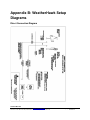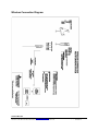
1
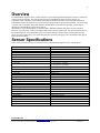
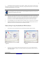
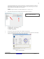
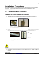
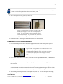
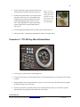
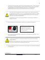
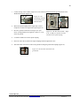
Signature Series User’s Manual Table of Contents Overview 1 Sensor Specifications 1 Site Considerations 2 2 2 3 Site Selection Ground Installations Roof Installations Power Considerations Solar Power AC Power Communication Considerations Direct Communication Cable Length Grounding Issues Wireless Communication Transmission Range Line-of-Sight Other Communication Options 4 4 4 4 4 5 5 5 5 5 6 Pre-Installation Tests 6 Installation Procedures 7 7 7 8 9 10 11 12 15 15 Procedure 1: TP1 Tripod Installation Procedures Procedure 1a: Tripod Preparation for Installation Procedure 1b: Ground Installations Procedure 1c: Flat Roof Installations Procedure 1d: Peaked Roof Installations Procedure 2: TP1-GK Guy-Wire Kit Installation Procedure 3: Mounting a WeatherHawk Station on a Tripod or Pole Procedure 4: Solar Panel Installation Procedure 5: TP1-GR Ground Kit Installation Appendix A: WeatherHawk Equipment Communications Options USB-AD Serial-to-USB Adapter RS485-KT Communications Module Kit Power Supplies SP2-KT 5 W Solar Panel Kit ACP2 AC Converter Mounting/Installation Kits TP1 Tripod/Mast Assembly TP1-TK Tripod Installation Kit TP1-SK Tripod Stake Kit TP1-MX Tripod Mast Extension TP1-GK Tripod Guy-wire Kit TP1-GR Tripod Grounding Kit HM Series (House Mount) Mast Components Appendix B: WeatherHawk Setup Diagrams Direct Connect Diagram Wireless Connect Diagram Roof/Wall Installation Diagram Appendix C: WeatherHawk Setup Special Notes Pyranometer Shipping Cap Removal Note Appendix D: Preventive Maintenance Procedures 1 Overview The WeatherHawk Signature Series weather station is a meteorological platform designed to measure a standard set of meteorological variables. The variables measured by the WeatherHawk Signature Series include: air temperature, relative humidity, solar radiation, precipitation, barometric pressure, and wind speed and direction. This weather station is designed for ease of use while providing reliable, long-term measurements. No special skills or special tools are needed to install and maintain a WeatherHawk system therefore providing a wide range of applications a WeatherHawk system can be used for. All instruments on the WeatherHawk are manufactured to published standards and require no user calibration. However, over time sensor accuracy will degrade and sensors will need replacement. For this reason all sensors on the WeatherHawk are easily replaceable by the user therefore making it unnecessary to send the platform to the factory for sensor replacement. User replaceable parts also cut down on shipping costs, and minimize data gaps in long term measurements. Sensor Specifications Table 1 below gives the accuracy of each sensor used in a WeatherHawk Signature Series weather station. Air Temperature Type Operating Range Sensor Accuracy In-system accuracy Relative Humidity Type Operating Range Accuracy Barometric Pressure Type Operating Range Accuracy Wind Speed Type Operating Range Starting Threshold Wind Direction Type Operating Range Sensitivity Rainfall Type Resolution Solar Radiation Type Range Accuracy 10K Thermistor -40 to 65° C (-40 to 150° F) +/- 0.5°C (+/- 0.9° F) +/- 1° C (+/- 1.8° F) Precision bulk-polymer device 0-100% +/- 3% (@25°C, 10-90%) +/- 5% (@25°C, 90-100%) Motorola MAP sensor 15-115 kPa Within 1.5% 3-Cup anemometer 0.78-98 m/s (1.75-214 mph) 0.78 m/s (1.75 mph) Vane 360° mechanical, 352° electrical 1 m/s (2.2 mph) Tipping Spoon 1 mm (0.04”) per tip Silicon Pyranometer 0-2000 W/m^2 +/- 5% Table 1: Instrument Specifications WeatherHawk® 815 W 1800 N Logan, UT 84321-1784, Email: [email protected] Toll free in USA: 866-670-5982, International: 435-227-9802, FAX: 435-227-9749 Copyright© 2004, 2013 Printed 2013 2 Site Considerations Certain aspects should be considered when choosing the best location to place a WeatherHawk system. To ensure the absolute best measurement, a weather station should be placed far away from any natural or artificial structure that could affect the measurement such as trees, buildings, artificial surfaces, steep slopes, etc. At times this is not possible, not practical, or not consistent with the application and decisions must be made as to the best location to place a weather station. The following sections will briefly discuss some considerations that should be made prior to installing a WeatherHawk station. Site Selection Ground Installations For ground installations, WeatherHawk recommends a TP1 Tripod Kit. However, the signature series weather station will mount on any tubing with an outer diameter of 1-1.5 inches and can be easily mounted on a usersupplied mast. With the TP1 Tripod Kit, the WeatherHawk can be mounted at a height of 38 to 60 inches. Mast extensions are available for the TP1 Tripod Kit in order to raise the height of the weather station. Guy-wire kits are also available for use with the TP1 Tripod Kit to enhance the stability of the mast. Other equipment for the TP1 Tripod Kit available from WeatherHawk includes a tripod installation kit, tripod stake kit, and a tripod grounding kit. The specific contents of all kits can be found in Appendix (A). Maximum station height with the tripod and accessories is 10 feet (3 meters). The ideal WeatherHawk site is level and well away from obstructions such as buildings, trees, and steep slopes. If obstructions exist, use the “Ten Times the Height Rule”, which is illustrated in Figure 1. Figure 1: Ten Times the Height Rule. If the height of the tree, T, is 13 feet and the height of the shed, H, is 12 feet, then the WeatherHawk station should be placed at least 130 feet from the tree and at least 120 feet from the shed. An option when obstructions exist is to raise the weather station height above the obstruction by using mast extensions or mounting the WeatherHawk on a roof. WeatherHawk® 815 W 1800 N Logan, UT 84321-1784, Email: [email protected] Toll free in USA: 866-670-5982, International: 435-227-9802, FAX: 435-227-9749 Copyright© 2004, 2013 Printed 2013 3 a. If the WeatherHawk station will be inside a fence to discourage vandalism, the fence top edge must be lower than the wind sensors even if the fence is chain-link b. Accurate wind measurements require the WeatherHawk to be located at the highest point in a particular region. c. The TP1 tripod/mast height cannot exceed 10 feet (312 cm), and you must use a guy-wire kit if you increase the mast to the maximum height. If you need a higher mounting structure contact WeatherHawk for recommendations. Roof Installations For roof mounts, WeatherHawk recommends either the TP1 Tripod Kit, Non-penetrating mast mount, or the HM3 Low Profile Mast Assembly. The HM3 is suitable for rooftop and well supported fascia board installations. WeatherHawk also offers mast extensions for the HM1 to increase the height of the sensor platform. The WeatherHawk needs to be 4 -8 feet (1.25 – 2.5 m) above the roof peak, which requires one or two extensions (TP1-MX) and a guy-wire kit (TP1-GK) when using the TP1 tripod and two extensions. If your roof has a chimney or is flat with decorative trim, or has nearby trees taller than the house, follow the “Ten Times the Height Rule” described in Figure 1. If a WeatherHawk is installed on a roof, heat reflected and radiated by the building tends to influence temperature and relative humidity readings of the station. Do not install your WeatherHawk near a functional chimney. When the chimney is in use, the carbon particles in the soot may degrade and damage the bearings in the sensors. The heat may also affect the air temperature and relative humidity measurements. Do not install your WeatherHawk on a mast or tripod with a television antenna because the additional wind loading from the WeatherHawk may cause the antenna mast to fail and topple. Because of electrical isolation and earth ground requirements, WeatherHawk recommends that a qualified electrician install and ground a directly connected roof mounted weather station. Your WeatherHawk Warranty is void if the weather station is not properly grounded. WeatherHawk® 815 W 1800 N Logan, UT 84321-1784, Email: [email protected] Toll free in USA: 866-670-5982, International: 435-227-9802, FAX: 435-227-9749 Copyright© 2004, 2013 Printed 2013 4 Power Considerations WeatherHawk weather stations are provided with an integral sealed rechargeable lead acid battery that must be recharged to assure continued system operation. The battery supplied with the WeatherHawk is a 0.8 AHr battery which will operate the station for approximately 3-4 days without any external charging. WeatherHawk also offers a 7 AHr external battery pack for use in higher latitudes and colder climates. To charge the internal or external battery, WeatherHawk offers a solar panel option or an AC/DC converter option. If no power supply has been ordered with the weather station, the user must provide an external DC power source with an output of 18 Volts @ 1.2 amps. Connecting an incompatible power source to your WeatherHawk voids your Warranty. Please check with WeatherHawk Customer Service before connecting a power source not purchased from WeatherHawk. Solar Power WeatherHawk offers a 5 Watt Solar Panel Kit for use with WeatherHawk Signature Series systems. The kit is suitable for use with any WeatherHawk Signature Series weather station however, if the station location is near or above 66° latitude, solar power is most likely not an option for recharging the internal battery of the weather station. Locations near or above 66° latitude do not receive enough sunlight in the winter months to effectively charge the internal battery using a solar panel. For these high latitude applications, the external 7 AHr battery is recommended. AC Power WeatherHawk offers an AC/DC Converter for use in recharging the battery using an AC power source. The ACP2 recharges the WeatherHawk battery by converting 110-220 VAC, 50/60 Hz power to 18 VDC. The ACP2 requires the weather station to be located within close proximity to a source of AC power. The ACP2 must be installed in a non-condensing environment or a weatherproof enclosure. The ACP2 is compatible with all WeatherHawk Signature Series weather stations. Communications Options Direct Communications Direct Communications with a WeatherHawk Signature Series weather station involves using an RS232 cable to directly connect the WeatherHawk to a host computer. To do this, the WeatherHawk must be located close enough to the host computer for a direct connection to be made. When using direct connection communications, it is very highly recommended that an isolation kit be used to protect the host computer in the event of a lightning strike or other electrical surge. WeatherHawk® 815 W 1800 N Logan, UT 84321-1784, Email: [email protected] Toll free in USA: 866-670-5982, International: 435-227-9802, FAX: 435-227-9749 Copyright© 2004, 2013 Printed 2013 5 Cable Lengths The maximum cable length for RS232 communications is 75 feet. If a user requires a longer cable length than this, an MD485-KT Communications Module Kit can be used. The MD485-KT Communications Module Kit enables the distance of direct communications to be lengthened to approximately 4000 feet of cable. However, if multiple WeatherHawk stations are used as in a network, the total combined cable length cannot exceed 4000 feet. Grounding Issues Outdoor cables may be subject to induced currents due to lightning or other environmental factors. Therefore proper grounding is imperative to avoid damage to the WeatherHawk and/or any connected host device or computer. To minimize the possibility of equipment damage or personal hazard, we strongly recommend a qualified electrician design and install the grounding and data isolation components of a directly wired installation. Wireless Communications WeatherHawk wireless stations use spread-spectrum radios to transmit the data over short distances. These radios must have line-of-sight between the station and the radio base station connected to a host computer to operate effectively. WeatherHawk wireless stations are available in three frequency ranges: 916 MHz, 922 MHz, and 2.4 GHz. Higher gain antennas are also available to increase the transmission distance of the data. Transmission Ranges Typical line-of-sight transmission ranges are listed below: Up to ½ mile (0.8 km) for the frequencies 916 MHz and 922 MHz Up to ¼ mile (0.4 km) for the frequency 2.4 GHz Up to 7 miles if optional higher gain antennas are used on both the WeatherHawk station and the RF base station The transmission ranges assume standard WeatherHawk antennas are used at the computer site. Usersupplied, higher gain antennas at the base station and/or on the WeatherHawk can affect the transmission range. The ranges assume no obstructions are in the line-of-sight. Line-of-Sight Line-of-sight is defined as a straight path between a transmitting and receiving antenna that is unobstructed by intermediate topography or obstructions (see Figure 2). A clear line-of-sight is required to achieve the optimum transmission range. Since the effect of obstructions on transmission range can vary, radio transmission tests should be performed before permanently installing a WeatherHawk station if obstructions lie within the line-of-sight. WeatherHawk® 815 W 1800 N Logan, UT 84321-1784, Email: [email protected] Toll free in USA: 866-670-5982, International: 435-227-9802, FAX: 435-227-9749 Copyright© 2004, 2013 Printed 2013 6 Station 1 Station 2 Figure 2: Line-of-sight. As the dotted line indicates, Station 1 has a clear line-of-sight with the Computer Site. The mountain obstructs Station 2's line-of-sight and would attenuate the RF signal or prevent wireless communications completely Other Communication Options WeatherHawk Signature Series weather stations can use other communications options if the application requires it. Other options include an IP server module that can send the data to an Ethernet making it accessible on a network. This option requires the purchase of a WeatherHawk IP server module, and the presence of an ethernet cable at the module location. Cellular communications can also be used to send the data from a location that is not within radio transmission range of the host computer. This option requires the purchase of a cellular modem, and cellular coverage at the site location. Another option is the use of satellite communication. This option requires purchasing the necessary hardware and a clear sky view from the station. Pre-Installation Tests Upon receiving a WeatherHawk weather station, it is a good idea to run some communication and software tests to ensure the system is working properly before permanently installing the station in the field. In order to test the system, the host computer will need an available serial port or a USB port with a serial-to-USB converter. A serialto-USB converter is available for purchase from WeatherHawk if necessary. Refer to the Quick Start Guide for preinstallation tests. WeatherHawk® 815 W 1800 N Logan, UT 84321-1784, Email: [email protected] Toll free in USA: 866-670-5982, International: 435-227-9802, FAX: 435-227-9749 Copyright© 2004, 2013 Printed 2013 7 Quick Start Guide Signature Series Model 232/916/922/240 Read Me First Computer Requirements Available Serial Port or USB Port (Serial-to-USB Converter Cable required) WeatherHawk Setup Procedure 1. Remove the top foam packing from the WeatherHawk box and verify you have all ordered equipment; then unpack equipment. a. Use the lift straps to remove the WeatherHawk station, since removing the station by lifting on the sensors may damage the sensors (see Figure 1). Lift Straps b. Avoid resting the WeatherHawk on the wind speed and wind direction sensors. c. Report missing or damaged equipment to WeatherHawk Customer Service before installing your system. Figure 1: Box of standard and wireless equipment. The lift straps allow easy removal of the WeatherHawk from the box. 2. Install your application software on your computer. 3. Connect the serial cable male connector to the WeatherHawk RS-232 port and the serial cable female connector to a computer serial port (Figure 2). Figure 2: Serial cable (left) and the WeatherHawk serial port in which the serial cable male connector connects. A dust cover must be removed from the WeatherHawk RS-232 port before connecting the cable. a. If you are using a serial connection, ensure the serial port is not already assigned to an open program. b. If you’re connecting the cable to a USB port, a serial-to-USB converter cable is required and optionally available from WeatherHawk (P/N 16878, USB-AD). 4. Turn the key to the on position (Figure 3), and observe a red flashing light through the small rectangular Scan/Receive window on the underside of the WeatherHawk. Figure 3: Keyed power switch is located on the bottom of the WeatherHawk station. WeatherHawk® 815 W 1800 N Logan, UT 84321-1784, Email: [email protected] Toll free in USA: 866-670-5982, International: 435-227-9802, FAX: 435-227-9749 Copyright© 2004, 2013 Printed 2013 8 5. Start application software and monitor the sensor displays. Within a couple of minutes, numerical values should appear confirming that the WeatherHawk is functioning. The lights labeled Scan/Receive on the underside of the station should also blink every ten seconds. If the WeatherHawk does not function properly, contact WeatherHawk Customer Service to solve the problem before continuing to the next steps. 6. Using your PC and weather station software, enter the setup parameters for the station. If you are using WeatherHawk PRO software, see the section in this document labeled “Station Setup usingWeatherHawk Pro Software”. If you are using other software, please refer to the software manual for that software. 7. Disconnect the serial cable from the WeatherHawk and place the dust cover back on the serial port. 8. If your WeatherHawk is wireless (Model 916/922/240), setup the radio (see “Radio Setup” section below). 9. Install the WeatherHawk weather station at the site. Refer to the Installation Guide provided on the CD shipped with your station for siting information and installation procedures. Station Setup Using WeatherHawk PRO Software 1. Click on the This Station menu and choose Setup from the drop down menu (Figure 4a and 4b). Figure 4a 2. Figure 4b Select Direct Connection from the setup screen and select the Serial Port on your computer which the serial cable is connected to. (Figure 5). If necessary, click the Change button next to the Serial PortI to select a different port. WeatherHawk® 815 W 1800 N Logan, UT 84321-1784, Email: [email protected] Toll free in USA: 866-670-5982, International: 435-227-9802, FAX: 435-227-9749 Copyright© 2004, 2013 Printed 2013 9 Figure 5: Select the correct Serial Port that is being used to communicate with the WeatherHawk. 3. Test the connection to the WeatherHawk by clicking the Test Connection button on the Setup screen. 4. Select Station Internal Saved Values from the list of Setups on the left of the setup screen. (See figure 6) Figure 6: Station Internal Saved Values Setup Screen 5. Enter the desired logging interval in minutes (Figure 6). 6. Enter the station Longitude and Latitude in decimal degrees. Enter station altitude in meters. (Figure 6). Longitude, Latitude, and Altitude can be determined with a GPS Receiver, a good topographical map, or found from an online source. WeatherHawk® 815 W 1800 N Logan, UT 84321-1784, Email: [email protected] Toll free in USA: 866-670-5982, International: 435-227-9802, FAX: 435-227-9749 Copyright© 2004, 2013 Printed 2013 10 The latitude and longitude must be entered as decimal degrees. If latitude and longitude are obtained in degrees-minutes-seconds, they must be converted. To convert the values todecimal, ignore the seconds, divide the minutes by 60, then add that value to the degrees. Example: Latitude is 41 degrees, 46 minutes, 58 seconds. Decimal value = 41 + (46/60) = 41.78 6. Select Weather Data from the list of Setups on the left of the Setup screen (figure 7) Figure 7: Weather Data settings 7. Set the Rain collector tip bucket size as follows a. Signature Series – 1mm (Standard) b. 500/600 Series - .01 mm c. All others – gauge specific 8. Set the Weather display update and Write data to database to the desired rate 9. Close the WeatherHawk PRO Setup window, click the connect button in lower right corner of main display window to test communication between software and weather station. Figure 8: WeatherHawk PRO WeatherHawk® 815 W 1800 N Logan, UT 84321-1784, Email: [email protected] Toll free in USA: 866-670-5982, International: 435-227-9802, FAX: 435-227-9749 Copyright© 2004, 2013 Printed 2013 11 Installation Procedures Many installation configurations for the WeatherHawk are possible. This document describes standard installation configurations. For questions about installation configurations not described in this document, contact WeatherHawk Customer Service. TP1 Tripod Installation Procedures Procedure 1a: Tripod Preparation for Installation. 1. Attach tripod feet to the legs of the tripod using the bolts and self-locking nuts provided (Figure 14). Figure 14: The TP1 Tripod Kit includes the nut and bolt (left) used to attach each foot to the tripod 2. If using mast extension(s), drive the extension(s) into the mast by inserting the tapered end of the extension into the top of the mast and striking the extension top with a wooden block or mallet (Figure 15). Mast exten Tripod mast Figure Figure 15: Mast extensions for use with the TP1 tripod kit Do not use a metal hammer to drive in the mast extension since this will deform the top of the mast extension. 3. If using the guy-wire kit, loosely install the guy-wire kit by following Procedure 2: RP1-KT Guy-Wire Kit Installation. WeatherHawk® 815 W 1800 N Logan, UT 84321-1784, Email: [email protected] Toll free in USA: 866-670-5982, International: 435-227-9802, FAX: 435-227-9749 Copyright© 2004, 2013 Printed 2013 12 Do not tighten the turnbuckles yet. The turnbuckles will be tightened in step 5 of Procedure 3: Mounting the WeatherHawk Station on a Tripod or Pole. 4. Install the mast in the tripod and adjust mast height if necessary (Figure 16). Figure 16: The mast fits in the center of the tripod. The mast height is adjusted by moving the tripod legs or removing the mast cup and sliding the mast up or down in the collars. Mast Tripod 5. Once the mast height has been set, tighten all six collar bolts. 6. Install the tripod at the site. Refer to “Procedure 1b: Ground Installations”, “Procedure 1c: Flat Roof Installation”, or “Procedure 1d: Peaked Roof Installations”. Procedure 1b: Ground Installations 1. If needed, prepare the site. A temporary site may require brush or tall weeds to be removed and footings dug if the site is not level. A permanent site may require pouring a concrete pad or fabricating some other form of a permanent base (See WeatherHawk website for a hole pattern drawing of the TP1 to assist in precast bolt alignment for permanent footings). 2. Use a rubber band to attach a level device, such as the one in the Tripod Installation Kit, to the midpoint of the tripod mast. 3. Place the tripod on the site. 4. Adjust tripod footings until the mast is level. Some adjustment is available by loosening/tightening the upper and lower collar bolts. If more adjustment is required, then for temporary sites, remove or replace soil under the TP1 feet. For permanent installations, use shims to adjust the foot foundation height. WeatherHawk® 815 W 1800 N Logan, UT 84321-1784, Email: [email protected] Toll free in USA: 866-670-5982, International: 435-227-9802, FAX: 435-227-9749 Copyright© 2004, 2013 Printed 2013 13 For temporary sites, ensure the soil under the tripod feet is well compacted. Otherwise the tripod may not remain level after the tripod feet have been secured to the ground. 5. Secure the tripod feet to the ground (See Figure 17). Figure 17: For temporary sites, drive the stakes of the TP1ST Kit (left) through the center hole in each tripod foot (right). The stakes should be driven in until they barely contact the foot surface. For permanent sites, install usersupplied bolts through the holes in each tripod foot. 6. Follow Procedure 3: Mounting the WeatherHawk Station on a Tripod or Pole. Procedure 1c: Flat Roof Installation 1. For each of the tripod feet, remove the protective paper from one side of the sealing pad to expose the adhesive then adhere the sealing pad to the bottom of the tripod foot (Figure 18). Sealing Pad Figure 18: The sealing pads, as well as other hardware used to attach the tripod feet to a roof, are included in the TP1 Tripod Kit. Either side of the sealing pad can be attached to the bottom of the tripod foot. Protective paper color may vary. 2. Use a rubber band to attach a level device, such as the one in the Tripod Installation Kit, to the midpoint of the tripod mast. 3. Place the tripod on the roof, remove the protective paper from the bottom of the sealing pads, and extend the tripod legs. 4. Position the tripod such that it is level and all of the foot pads are flat on the roof. Some adjustment is available after the tripod has been attached to the roof by loosening/tightening the upper and lower collar bolts. If more adjustment is required, use shims to adjust the foot foundation height until the mast is level. 5. Screw the lag bolts through the holes of each tripod foot (Figure 19). The bolts must pierce the sealing pads. WeatherHawk® 815 W 1800 N Logan, UT 84321-1784, Email: [email protected] Toll free in USA: 866-670-5982, International: 435-227-9802, FAX: 435-227-9749 Copyright© 2004, 2013 Printed 2013 14 Figure 19: The TP1 Tripod Kit includes the lag bolts used to secure the TP1 to a roof. Two lag bolts are used for each foot. The bolts must pierce the sealing pad. 6. Lag Bolt Lag Bolt Follow Procedure 3: Mount the WeatherHawk Station on a Tripod or Pole. Procedure 1d: Peaked Roof Installation The WeatherHawk wind sensors should be at least 8 feet (2.5m) above the roof peak, which requires two extensions (TP1-MX) and a guy-wire kit (TP1-GK). If using the HM1 please refer to Appendix B for setup diagram 1. For each of the tripod feet, remove the protective paper from one side of the sealing pad to expose the adhesive then adhere the sealing pad to the bottom of the tripod foot (Figure 20). Sealing Pad 2. 3. Figure 20: The sealing pads, as well as other hardware used to attach the tripod feet to a roof, are included in the TP1 Tripod Kit. Either side of the sealing pad can be attached to the bottom of the tripod foot. Protective paper color may vary. Use a rubber band to attach a level device, such as the one in the Tripod Installation Kit, to the midpoint of the tripod mast. Place the tripod at the peak of the roof with one foot pad on one side and two foot pads on the other side of the peak (Figure 21). Figure 21: Proper placement of the tripod on a peaked roof. When properly placed, all foot pads rest flat on the roof. WeatherHawk® 815 W 1800 N Logan, UT 84321-1784, Email: [email protected] Toll free in USA: 866-670-5982, International: 435-227-9802, FAX: 435-227-9749 Copyright© 2004, 2013 Printed 2013 15 4. 5. Remove the protective paper form the bottom of the sealing pads and extend the tripod legs (Figure 22). Position the tripod such that it is level and all of the foot pads are flat on the roof. Some adjustment is available after the tripod is attached to the roof by loosening/tightening the upper and lower collar bolts. If more adjustment is required, make minor position changes in the tripod assembly until the mast is level. Figure 22: The Tripod Kit includes the lag bolts. Two lag bolts are used for each foot. The bolts must pierce the sealing pads. 6. Screw the lag bolts through the holes in each tripod foot and into the roof. 7. Follow Procedure 3: Mounting the WeatherHawk Station on a Tripod or Pole. Lag Bolt Lag Bolt Procedure 2: TP1-GK Guy Wire Kit Installation Guy-Wire Clamps Turnbuckles Bracket S-Hooks 1. Cut the guy-wire cable into three equal length pieces. 2. Loop one end of each guy-wire through a Bracket eye-bolt and clamp the guy-wire using one of the Clamps provided. 3. Install the Bracket on the tripod mast about six inches (15 cm) from the top of the mast then loosely tighten the bracket bots that lock it to the mast. 4. Insert the mast into the Tripod and rotate the mast assembly until the bracket eye-bolts all line up with a tripod leg then loosely tighten the mast collar bolts on the tripod. WeatherHawk® 815 W 1800 N Logan, UT 84321-1784, Email: [email protected] Toll free in USA: 866-670-5982, International: 435-227-9802, FAX: 435-227-9749 Copyright© 2004, 2013 Printed 2013 16 5. Tighten the guy-wire bracket bolts until they deform the mast by dimpling the surface to assure the bracket does not slide when the turnbuckles are tightened. 6. Unscrew the turnbuckle until approximately 80% of both eye bolt threads extend beyond the turnbuckle body. 7. Hook an S-hook to an eyelet on each of the tripod feet. Alternatively, the S-hooks can be connected to user-supplied eye-bolts set into a concrete pad or another fixed structure. 8. One at a time, grasp a guy-wire and loop it around its corresponding S-hook to roughly determine its correct length then cut the guy-wires to eliminate any excess length. 9. Hook the unattached end of each S-hook to an eyebolt on the end of a turnbuckle. 10. Loop the free end of each guy-wire through its respective turnbuckle eye-bolt and pull it tightly then clamp the guy-wire using one of the clamps provided. a. The guy-wires need to remain loose until after the WeatherHawk assembly has been properly oriented. The turn-buckles are tightened in step 5 of Procedure 3: Mounting the WeatherHawk Station on a Tripod or Pole. b. Guy-wires will stretch for a few weeks after installation. You should periodically check them for tension and re-tighten the turnbuckles as required until they stop stretching. Procedure 3: Mounting a Signature Series Station on a Tripod or Pole This procedure assumes the WeatherHawk has been setup and tested at the computer location, and that a tripod or pole has been installed at the site. 1. Place your WeatherHawk assembly on top of the mast or pole with the base firmly seated on the top edge of the mast or pole (Figure 23). WeatherHawk Base Figure 23: The WeatherHawk assembly properly seated on a mast or pole. Mast or Pole WeatherHawk® 815 W 1800 N Logan, UT 84321-1784, Email: [email protected] Toll free in USA: 866-670-5982, International: 435-227-9802, FAX: 435-227-9749 Copyright© 2004, 2013 Printed 2013 17 2. Loosely tighten the U-bolt nuts so that the WeatherHawk is stable but can be rotated on the mast or pole (Figure 24). U-Bolt Nuts Figure 24: Two views of the WeatherHawk station. The U-bolt and nuts are shown. 3. As a reference, use a magnetic compass (supplied with the optional Tripod Installation Kit) and rotate the WeatherHawk assembly until the reference line on the wind direction sensor is aligned with Magnetic North (Figure 25). N Figure 25: Accurate wind direction measurements require the reference line on the wind direction sensor to be aligned with Magnetic North. N 4. Firmly tighten the U-bolt nuts. 5. If the TP1-GK Guy-Wire Kit has been installed, assure that its orientation will not interfere with the solar panel (if installed), then evenly tighten the turnbuckles to tension the guy-wires. 6. Confirm the WeatherHawk is level by viewing the bubble level on of the WeatherHawk. Minor adjustments can be made by tightening or loosening the appropriate guy-wire turnbuckle, placing shims between the WeatherHawk base and the top of the TP1 mast or pole, or loosening the mast bolts at the top and bottom of the TP1 tripod and shifting the vertical orientation (Figure 26). top Bubble l Figure 26: The bubble level confirms the station is level, which is required for accurate rainfall and solar radiation measurements. WeatherHawk® 815 W 1800 N Logan, UT 84321-1784, Email: [email protected] Toll free in USA: 866-670-5982, International: 435-227-9802, FAX: 435-227-9749 Copyright© 2004, 2013 Printed 2013 18 7. Connect the power source that will recharge the internal sealed rechargeable battery. If using a solar panel, follow Procedure 4: Solar Panel Installation. If using an external power supply, assure it was purchased from WeatherHawk for use with the WeatherHawk weather station or, if not purchased from WeatherHawk, that it has an output of 18 VDC and that all connections are weatherproof. a. The internal sealed rechargeable battery must be recharged to assure continued system function. b. Connecting an incompatible power source to your WeatherHawk negates our Warranty. Therefore WeatherHawk recommends you check with WeatherHawk Customer Service before connecting a power source not purchased from WeatherHawk. c. WeatherHawk’s ACP1 AC Converter must be installed in a non-condensing environment or a weatherproof enclosure. 8. Remove and discard the red or green protective cap from the solar radiation sensor (Figure 27). Figure 27: A red or green cap protects the solar radiation sensor while the WeatherHawk is being shipped and installed. Accurate measurements require the cap to be removed. 9. Properly ground the WeatherHawk station. If using the TP1-GR Ground Kit, refer to Procedure 5: TP1GR Ground Kit Installation. a. The TP1-GR Ground Kit is for ground located installations only. Do no use the TP1-GR for rooftop installations. b. Because proper grounding of the system is required for both safety and reliable system function, we recommend a qualified electrician install the grounding system. 10. Turn the weather station key to the on position and return to the computer site to confirm the WeatherHawk is working properly. WeatherHawk® 815 W 1800 N Logan, UT 84321-1784, Email: [email protected] Toll free in USA: 866-670-5982, International: 435-227-9802, FAX: 435-227-9749 Copyright© 2004, 2013 Printed 2013 19 Procedure 4: Solar Panel Installation 1. Place the solar panel on the mast below the station to the maximum distance allowed by the solar panel cable. 2. Loosely tighten the U-bolt so that the solar panel is stable but can be rotated on the mast or pole. 3. Use a compass (supplied in the optional Tripod Installation Kit) to properly align the solar panel. If the site is in the northern hemisphere, the glass surface of the panel should face south. If the site is in the southern hemisphere, the glass surface of the 5 W Solar Panel panel should face north. 4. Connect the cable to the WeatherHawk connector labeled “Solar Panel”. Procedure 5: TP1-GR Ground Kit Installation a. Proper earth grounding of the system may be required for both personal safety and reliable system function, we recommend a qualified electrician install the grounding kit. b. If the station is directly connected to the Host computer but not properly grounded and isolated, the Host computer can be damaged by environmentally induced electrical surges. c. This kit is for ground installations only. Do not use the TP1-GR kit for rooftop installations. A qualified electrician should specify and install the earth ground system for a roof mounted weather station, if required. 14 AWG copper wire Tripod coupling Ground rod coupling Ground rod #4 stranded copper cable WeatherHawk® 815 W 1800 N Logan, UT 84321-1784, Email: [email protected] Toll free in USA: 866-670-5982, International: 435-227-9802, FAX: 435-227-9749 Copyright© 2004, 2013 Printed 2013 20 1. Connect the lug of the 14 AWG copper wire to the connector labeled Ground Lug on the bottom of the WeatherHawk station (Figure 28). Lug Figure 28: The ground lug connected to the bottom of the WeatherHawk. 1 2 2. Mount the tripod coupling on the tripod mast so that it clamps the 14 AWG wire against the tripod (Figure 29). 3. Drive the ground rod into the soil using a fence post driver or sledge hammer leaving about 3 inches (7.5 cm) above the ground. 4. Loosen the middle screw in the tripod coupling. 5. Place one end of the #4 cable in the tripod coupling hole then tighten the screw. 6. Attach the other end of the #4 cable to the ground rod using the ground rod coupling (Figure 30). Figure 29: The TP1-GK assembly. Right is the 14 AWG wire and the #4 cable attached to the tripod coupling. Figure 30: The #4 cable connected to the ground rod. WeatherHawk® 815 W 1800 N Logan, UT 84321-1784, Email: [email protected] Toll free in USA: 866-670-5982, International: 435-227-9802, FAX: 435-227-9749 Copyright© 2004, 2013 Printed 2013 Appendix A: WeatherHawk Equipment The following equipment is available from WeatherHawk and these items can be ordered on-line at http://www.weatherhawk.com. Contact WeatherHawk Customer Service for questions concerning the use of the following equipment. Communications Options USB-AD Serial-to-USB Adapter The USB-AD Serial-to-USB Adapter is required if you’re your computer has a USB port to communicate with the WeatherHawk. The USB-AD Serial-to-USB Adapter is a Universal Serial Bus (USB) converter that provides a plug and play RS-232 serial connection to a USB input on a computer. Data rates up to 230 kbps are supported. The USB-AD includes a Universal Serial Bus (USB) Converter with a 1 meter cable This product is commercially produced and may not always be available in this specific configuration. WeatherHawk may substitute a part of equal or greater value if this device is discontinued by the manufacturer. RS485-KT Communications Module Kit The RS485-KT enables wired connections between the WeatherHawk 232 weather station and a Host computer (PC) for up to 4,000 feet (1300 meters). The customer must supply a CAT 5 grade cable, between the WeatherHawk and the Host computer, with each end terminating in RJ-11 connectors. The RS485-KT includes: Opto-isolated RS485 interface module for the Host PC Power supply for the RS485 module located at the Host PC RS485 interface module for the WeatherHawk weather station The RS485 module for the WeatherHawk is not weatherproof and must be installed in a non-condensing environment within 50 feet of the WeatherHawk station, or in a weatherproof enclosure at the WeatherHawk station. Power Supplies WeatherHawk® 815 W 1800 N Logan, UT 84321-1784, Email: [email protected] Toll free in USA: 866-670-5982, International: 435-227-9802, FAX: 435-227-9749 Copyright© 2004, 2013 Printed 2013 SP2-KT 5 W Solar Panel Kit This solar panel is for use with any WeatherHawk Signature Series weather station. It recharges the internal battery and has a 72 inch2 surface area and produces 5 watts at a peak of 17.1 volts. The SP2-KT includes 5 W solar panel Mounting hardware ACP2 AC Converter The ACP2 recharges the WeatherHawk battery by converting 110-220 VAC, 50/60 Hz power to 18 VDC. The ACP2 must be installed in a non-condensing environment or a weatherproof enclosure. The ACP2 includes UL-approved, AC/DC converter with US Standard plug prongs 20 feet (6.2 m), UV resistant waterproof cable with an environmental connector for connecting to the WeatherHawk. Mounting/Installation Kits TP1-Tripod/Mast Assembly The TP1 tripod/mast assembly provides a stable support for the WeatherHawk and is suitable for both ground and rooftop installations. The TP1 includes Tripod Mast that places the WeatherHawk wind sensors at a height of 38” to 60” (99 to 156 cm) Kit that includes (3) tripod feet with hardware, (6) lag bolts (used for rooftop installation only), and 3 sealing pads (used for rooftop installations only) WeatherHawk® 815 W 1800 N Logan, UT 84321-1784, Email: [email protected] Toll free in USA: 866-670-5982, International: 435-227-9802, FAX: 435-227-9749 Copyright© 2004, 2013 Printed 2013 TP1-TK Tripod Installation Kit This kit includes equipment that helps you install the WeatherHawk to the correct 3-axis vertical orientation and to align the station to the magnetic north. Using the TP1-KT to properly orient the weather station helps assure accurate measurements. The TP1-KT includes: Multi-axis bubble level Compass Rubber band for attaching the bubble level to the tripod mast TP1-SK Tripod Stake Kit The TP21-SK is for anchoring the tripod to the soil. It is intended for temporary installations and sites that experience light to moderate wind speeds. The TP1-SK includes: (3) ½” (1.27 cm) diameter solid steel spikes with a welded hammer cap on one end The above pictured stake kit may be replaced by three galvanized steel spikes that offer equal or better holding ability. Substitution is at the discretion of WeatherHawk based on product availability at the time of order. Sites that may experience high wind speeds should not use this kit. For those sites, anchor the tripod with bolts and guy-wires fastened to a concrete pad or other permanent base. TP1-MX Tripod Mast Extension The TP1-MX extension fits into a1- ¼” diameter post and is used to increase the height of the WeatherHawk wind sensors (See TP1 installation procedures). When used with the TP1, one extension provides a wind sensor height of 69” to 89” (179 to 231 cm). A second TP1-MX can be used to provide a wind sensor height of 98” to 120” (225 to 312 cm). The TP1-MX includes 1¼” (32.5 mm) OD 35” (89 cm) long steel post with one end crimped WeatherHawk® 815 W 1800 N Logan, UT 84321-1784, Email: [email protected] Toll free in USA: 866-670-5982, International: 435-227-9802, FAX: 435-227-9749 Copyright© 2004, 2013 Printed 2013 a. Do not use more than two TP1-MX extensions with the TP1 Tripod Assembly. b. When two TP1-MX extensions are used, the TP1-GK Guy-wire Kit is also recommended. TP1-GK Tripod Guy-Wire Kit The TP1-GK is used to increase the tripod’s stability (see Procedure 3: Guy-wire Kit Installation). It is intended for permanent installations, installations subject to consistently high wind speeds, or TP1 tripods using two mast extensions. The TP1-GK includes: Plastic-coated, steel guy-wire cable Bracket for securing guy-wires to the TP1 mast (3) S-hooks (3) turnbuckles (6) clamps TP1-GR Tripod Grounding Kit The TP1-GR provides hardware needed to properly ground the WeatherHawk and tripod. Properly grounding the station prevents electrical surges and lightning from damaging the WeatherHawk. The TP1-GR includes: 36” (91.4 cm) long copper sheathed steel electrical ground rod Electrical couplings for connection to the ground rod and tripod 5 ft. length of plastic coated, #4 stranded copper cable 3 ft. length of 14 AWG stranded copper wire with a connection lug on one end a. Because proper grounding of the system is required for both personal safety and reliable system function, we recommend a qualified electrician install the grounding kit. b. If the station is not properly grounded, a computer connected to the WeatheHawk can also be damaged by electrical surges. c. This kit is for ground installations only. A qualified electrician should design and install the grounding system for a roof mounted station. WeatherHawk® 815 W 1800 N Logan, UT 84321-1784, Email: [email protected] Toll free in USA: 866-670-5982, International: 435-227-9802, FAX: 435-227-9749 Copyright© 2004, 2013 Printed 2013 HM3 Low Profile Mast Assembly The HM3 Low Profile Mast Assembly is a modified satellite dish mast. It provides a stable support for the WeatherHawk and is suitable for rooftop and well supported fascia board installations. Refer to Appendix B for installation instructions. The HM3 includes: Foot Mast 48” (122 cm) high Kit that includes (6) lag bolts and (3) sealing pads (used for rooftop installations) HM-EXT HM Series Mast Extension The HM-EXT extension fits into the HM Series mast assembly and is used to increase the height of the WeatherHawk wind sensors. The HM-EXT includes: One 35” (89 cm) long steel post with on end crimped a. Do not use more than two HM-EXT extensions with an HM Series Mast Assembly b. When two HM-EXT extensions are used, the TP1-GK Guy-wire Kit is also recommended WeatherHawk® 815 W 1800 N Logan, UT 84321-1784, Email: [email protected] Toll free in USA: 866-670-5982, International: 435-227-9802, FAX: 435-227-9749 Copyright© 2004, 2013 Printed 2013 Appendix B: WeatherHawk Setup Diagrams Direct Connection Diagram WeatherHawk® 815 W 1800 N Logan, UT 84321-1784, Email: [email protected] Toll free in USA: 866-670-5982, International: 435-227-9802, FAX: 435-227-9749 Copyright© 2004, 2013 Printed 2013 Wireless Connection Diagram WeatherHawk® 815 W 1800 N Logan, UT 84321-1784, Email: [email protected] Toll free in USA: 866-670-5982, International: 435-227-9802, FAX: 435-227-9749 Copyright© 2004, 2013 Printed 2013 HM1 Low Profile Mast Assembly Diagram WeatherHawk® 815 W 1800 N Logan, UT 84321-1784, Email: [email protected] Toll free in USA: 866-670-5982, International: 435-227-9802, FAX: 435-227-9749 Copyright© 2004, 2013 Printed 2013 Appendix C: WeatherHawk Setup Special Notes Important Installation Information: 1. Remove and discard Green protective cap from Solar Radiation sensor at the completion of site installation. 500 Series Weather Station Signature Series Weather Station Solar Radiation Protective Shipping Covers 2. Ensure that the system is properly connected to an earth ground using the ground lug on the bottom of the weather station. Failure to properly ground the system will result in sensor head damage and also void the Warranty. WeatherHawk® 815 W 1800 N Logan, UT 84321-1784, Email: [email protected] Toll free in USA: 866-670-5982, International: 435-227-9802, FAX: 435-227-9749 Copyright© 2004, 2013 Printed 2013 Appendix D: Preventive Maintenance Procedures Preventive Maintenance is important to ensure the continued quality operation of WeatheHawk weather stations. The following checks should be performed at least once a month to maintain continued operation of the WeatherHawk. Inspect entire mounting system for security and damage. o Tighten any loose nuts/bolts o Repair/replace any damaged mounting components Check the bubble level on the WeatherHawk to ensure system is still level o Re-level platform if not level Inspect the instrument platform for cracks and damage. o If the WeatherHawk housing is cracked or damaged, contact WeatherHawk Customer Service to discuss the issue as a cracked housing could allow water/moisture to penetrate inner electronics Inspect communication and power cables o Repair/replace any damaged cables Inspect Temperature/RH sensor housing for debris and damage o Remove any debris found on sensor housing o Replace any damaged sensor housing Inspect the inside of the rain gauge for debris/bugs/spiders o Remove the top cover of the rain gauge to access the inside of gauge Remove any foreign debris, insects, or spiders inside gauge DO NOT spray insect or spider killer inside of rain gauge as this could damage internal electronics of gauge. Inspect cleanliness of solar radiation sensor (pyranometer) o Clean pyranometer as necessary with a lightly damped cloth Check wind speed sensor for free operation and noisy bearings o Replace sensor if operation feels hindered Check wind direction sensor for free operation and noisy bearings o Replace sensor if operation feels hindered Check alignment of wind direction sensor reference mark o Re-align sensor if reference mark does not face magnetic north WeatherHawk® 815 W 1800 N Logan, UT 84321-1784, Email: [email protected] Toll free in USA: 866-670-5982, International: 435-227-9802, FAX: 435-227-9749 Copyright© 2004, 2013 Printed 2013 WeatherHawk® 815 W 1800 N Logan, UT 84321-1784, Email: [email protected] Toll free in USA: 866-670-5982, International: 435-227-9802, FAX: 435-227-9749 Copyright© 2004, 2013 Printed 2013