1
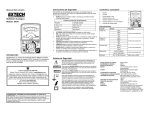
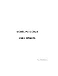
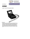
User’s Guide
Safety Instructions
Controls and Jacks
This meter has been designed for safe use, but must be operated with caution.
The rules listed below must be carefully followed for safe operation.
1.
NEVER apply voltage or current to the meter that exceeds the specified
maximum:
Input Protection Limits
Analog Multimeter
Function
Model 38070
V DC or V AC
500V AC and DC
mA DC
500mA DC
Resistance
50V DC/AC
2.
3.
4.
5.
6.
7.
8.
Maximum Input
USE EXTREME CAUTION when working with high voltages.
DO NOT measure voltage if the voltage on the "COM" input jack exceeds
500V above earth ground.
NEVER connect the meter leads across a voltage source while the
function switch is in the current or resistance mode. Doing so can
damage the meter.
ALWAYS discharge filter capacitors in power supplies and disconnect the
power when making resistance tests.
ALWAYS turn off power and disconnect test leads before opening the
covers to replace the fuse or battery.
NEVER operate the meter unless the back cover and the battery and fuse
covers are in place and fastened securely.
If the equipment is used in a manner not specified by the manufacturer,
the protection provided by the equipment may be impaired.
Safety Symbols
This symbol adjacent to another symbol, terminal or operating
device indicates that the operator must refer to an explanation
in the Operating Instructions to avoid personal injury or damage
to the meter.
Introduction
Congratulations on your purchase of the Extech model 38070 Analog
Multimeter. This device measures AC/DC Voltage, DC Current, Resistance,
and dB, displaying measurements in analog format. Properly used, this meter
will provide many years of reliable service.
WARNING
CAUTION
Support line (781) 890-7440
Technical support: Extension 200; E-mail: [email protected]
Repair & Returns: Extension 210; E-mail: [email protected]
Product specifications subject to change without notice
For the latest version of this User’s Guide, Software updates, and other upto-the-minute product information, visit our website: www.extech.com
Extech Instruments Corporation, 285 Bear Hill Rd., Waltham, MA 02451
WARNING: USE EXTREME CAUTION IN THE USE OF THIS DEVICE.
Improper use of this device can result in injury or death. Follow all safeguards
suggested in this manual in addition to the normal safety precautions used in
working with electrical circuits. DO NOT service this device if you are not
qualified to do so.
MAX
500V
This WARNING symbol indicates a potentially hazardous
situation, which if not avoided, could result in death or serious
injury.
This CAUTION symbol indicates a potentially hazardous
situation, which if not avoided, may result damage to the
product.
This symbol advises the user that the terminal(s) so marked
must not be connected to a circuit point at which the voltage
with respect to earth ground exceeds 500V.
This symbol adjacent to one or more terminals identifies them
as being associated with ranges that may, in normal use, be
subjected to particularly hazardous voltages. For maximum
safety, the meter and its test leads should not be handled when
these terminals are energized.
This symbol indicates that a device is protected throughout by
double insulation or reinforced insulation.
1
2
3
1.
2.
3.
4.
5.
Scale
Pointer
Scale zero adjust
Ohms zero adjust
Rotary function switch
6.
7.
Positive V, mA and Ω input jack
COM input jack
4
5
6
7
Specifications
Function
DC Voltage
Range
Accuracy
500V
250V
50V
10V
AC Voltage
(50/60Hz)
500V
250V
50V
10V
DC Current
250mA
50Ma
0.5mA
Resistance
Decibels
Rx10 (10,000Ω)
Rx1k (1,000,000Ω)
-10 to +56 dB (4 ranges)
Max input voltage
Input Sensitivity,
Frequency Range
Battery
Fuse
Operating Temperature
Storage Temperature
Operating Humidity
Storage Humidity
Operating Altitude
Weight
Size
Safety
± 4% of full scale
± 5% of full scale
± 4% of full scale
± 5% of full scale
0dB=1mW in 600Ω
500V AC/DC
2kΩ/V
50/60Hz
0ne (1) 1.5V AA battery
500mA/250 fast blow (5mmx20mm)
41oF to 104oF (5oC to 40oC)
14oF to 122oF (-10oC to 50oC)
Max 80% up to 87ºF (31ºC) decreasing linearly to
50% at 104ºF (40ºC)
<80%
7000ft. (2000meters) maximum.
3.88oz (110g)
3.82x3.34x1.3” (97x65x33mm)
For indoor use and in accordance with the
requirements for double insulation to IEC1010-1
(1995): EN61010-1 (1995) Overvoltage Category II
500V, Pollution Degree 2. UL, CE Approved
Battery Installation
AC VOLTAGE MEASUREMENT
WARNING: To avoid electric shock, always turn off the power and
disconnect the test leads before opening the back to replace the fuse or
battery.
1. Remove the screws securing the rear cover using a Phillips head
screwdriver.
2. Lift the cover off and replace the battery observing the correct polarity.
3. Insert the new battery into the battery holder.
Replace the rear cover and secure with the screws. WARNING: To avoid
electric shock, do not operate the meter until the battery cover is in place
and fastened securely.
NOTE: If your meter does not work properly, check the fuses and battery to
make sure that they are still good and that they are properly inserted.
Operating Instructions
CAUTION: Do not measure AC voltages if a motor on the circuit is being
switched ON or OFF. Large voltage surges may occur that can damage
the meter.
1.
2.
3.
WARNING: Risk of electrocution. High-voltage circuits, both AC and DC, are
very dangerous and should be measured with great care.
1. ALWAYS turn the function switch to the OFF position when the meter is not
in use.
Maintenance
WARNING: Risk of Electrocution. The probe tips may not be long enough
to contact the live parts inside some 240V outlets for appliances because
the contacts are recessed deep in the outlets. As a result, the reading may
show 0 volts when the outlet actually has voltage on it. Make sure the
probe tips are touching the metal contacts inside the outlet before
assuming that no voltage is present.
4.
Set the function switch to the highest V AC position.
Insert the black test lead banana plug into the
negative (COM) jack.
Insert red test lead banana plug into the positive (V)
jack.
Touch the black test probe tip to the negative side
of the circuit.
Touch the red test probe tip to the positive side of
the circuit.
Read the voltage in the display. Reset the function
switch to successively lower V AC positions to
obtain a higher scale reading.
DC VOLTAGE MEASUREMENTS
CAUTION: Do not measure DC voltages if a motor on the circuit is being
switched ON or OFF. Large voltage surges may occur that can damage
the meter.
1.
2.
3.
4.
Set the function switch to the highest V DC position.
Insert the black test lead banana plug into the
negative (COM) jack.
Insert the red test lead banana plug into the positive
(V) jack.
Touch the black test probe tip to the negative side of
the circuit.
Touch the red test probe tip to the positive side of the
circuit.
Read the voltage in the display. Reset the function
switch to successively lower V DC positions to obtain
a higher scale reading.
DC CURRENT MEASUREMENTS
1.
Insert the black test lead banana plug into the negative
(COM) jack.
2.
Set the function switch to the 250mA DC position and
insert the red test lead banana plug into the (mA) jack.
Remove power from the circuit under test, then open up
the circuit at the point where you wish to measure
current.
Touch the black test probe tip to the negative side of
the circuit.
Touch the red test probe tip to the positive side of the
circuit.
Apply power to the circuit.
Read the current in the display. Reset the function
switch to successively lower mA positions to obtain a higher scale reading.
3.
4.
5.
6.
RESISTANCE MEASUREMENTS
WARNING: To avoid electric shock, disconnect power to the unit under
test and discharge all capacitors before taking any resistance
measurements. Remove the batteries and unplug the line cords.
1.
2.
3.
4.
5.
Set the function switch to the X10 or X1K position.
Insert the black test lead banana plug into the negative
(COM) jack
Insert the red test lead banana plug into the positive Ω
jack.
Touch the test probe tips together and adjust the OHM
Zero Adjust knob for a “0” reading.
Touch the test probe tips across the circuit or part under
test. It is best to disconnect one side of the part under
test so the rest of the circuit will not interfere with the
resistance reading.
Read the resistance on the scale
dB MEASUREMENTS
The dB scale can be used to measure the milliwatt power dissipation on a
600Ω load by measuring the voltage across a 600 Ω load. An AC voltage of
0.775Vrms across 600Ω is equal to 1mW or “0”dB When converting an AC
Voltage measurement to dB take the dB reading from the lowest arc on the
scale plate and then add the appropriate dB correction found in the table
below.
ACV
10
50
250
500
ADD
0
14
28
34
dB
-10 ~ 22
4 ~ 36
18 ~ 50
24 ~ 56
WARNING: To avoid electric shock, disconnect the test leads from any
source of voltage before removing the back cover or the battery or fuse
covers.
WARNING: To avoid electric shock, do not operate your meter until the
battery and fuse covers are in place and fastened securely.
This MultiMeter is designed to provide years of dependable service, if the
following care instructions are performed:
1.
KEEP THE METER DRY. If it gets wet, dry it immediately.
2.
USE AND STORE THE METER IN NORMAL TEMPERATURES.
Temperature extremes can shorten the life of the electronic parts and
distort or melt plastic parts.
3.
HANDLE THE METER GENTLY AND CAREFULLY. Dropping it can
damage the electronic parts or the case.
4.
KEEP THE METER CLEAN. Wipe the case occasionally with a damp
cloth. DO NOT use chemicals, cleaning solvents, or detergents.
5.
USE ONLY FRESH BATTERIES OF THE RECOMMENDED SIZE AND
TYPE. Remove old or weak batteries so they do not leak and damage the
unit.
6.
IF THE METER IS TO BE STORED FOR A LONG PERIOD OF TIME,
the batteries should be removed to prevent damage to the unit.
UL LISTED
The UL mark does not indicate that this product has been evaluated for the
accuracy of its readings.
Warranty
EXTECH INSTRUMENTS CORPORATION warrants this instrument
to be free of defects in parts and workmanship for one year from date
of shipment (a six month limited warranty applies on sensors and
cables). If it should become necessary to return the instrument for
service during or beyond the warranty period, contact the Customer
Service Department at (781) 890-7440 ext. 210 for authorization. A
Return Authorization (RA) number must be issued before any
product is returned to Extech. The sender is responsible for
shipping charges, freight, insurance and proper packaging to prevent
damage in transit. This warranty does not apply to defects resulting
from action of the user such as misuse, improper wiring, operation
outside of specification, improper maintenance or repair, or
unauthorized modification. Extech specifically disclaims any implied
warranties or merchantability or fitness for a specific purpose and will
not be liable for any direct, indirect, incidental or consequential
damages. Extech's total liability is limited to repair or replacement of
the product. The warranty set forth above is inclusive and no other
warranty, whether written or oral, is expressed or implied.
Repair and Calibration Services
Extech offers complete repair and calibration services for all Extech
products. For periodic calibration, NIST certification or repair of any Extech
product, call customer service for details on services available. Extech
recommends that calibration be performed on an annual basis to insure
calibration integrity.
Copyright © 2006 Extech Instruments Corporation. All rights reserved
including the right of reproduction in whole or in part in any form.
38070 V3.0
01/07