1
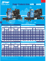
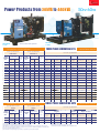
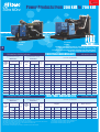
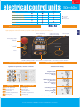
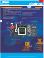
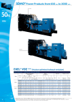
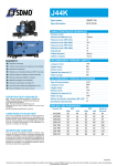
113*/%0(# 1PXFS1SPEVDUT );); 6kVA-700kVA 11kW-600kW "QPXFSGVMSFTQPOTF SDMO is recognised as one of the top manufacturers of g e n e r a t i n g s e t s in the world. SDMO has channelled all its energy into designing a range which is both highly competitive and high-performance, the largest range available on the market. As a response to the increasingly precise nature of your energy requirements, which relate directly to the special traits of your particular industry, SDMO is devoting the majority of its resources to the continuous improvement of its range and services. The result of a strategy focussed on a single industry: a professional requirement which guarantees you a reliable source of energy, complying with the strictest of standards. The pioneering mindset of its teams, and the mastery and flexibility of its production methods mean that SDMO is constantly innovating. The proximity of its distribution network and dynamism of its customer services policy enable SDMO to be a powerful force and provide the basis of the company's values. SDMO, the source of energy for your comfort and safety. SDMO, providing energy to connect people. XIBUFWFS UIFFOFSHZSFRVJSFE www.sdmo.com Whether you require emergency power to be able to cope with potential power cuts (e.g. hospitals, shopping centres) or continuous power when conventional electrical grids are faulty (power plants), SDMO will be able to offer you performance products from a large range which meets all the requirements of different markets. This range comprises 3 main categories: - Standard products (Portable Power, Residential Power, Power Products and Rental Power) - Expertise and Services (Power Solutions, Training, Spare Parts, Technical Assistance) - Related products (Nexys, Telys, Kerys command/control units) /BUJPOBMDPWFSBHF JOUFSOBUJPOBMQSFTFODF ££UIJOLHMPCBMMZBDU MPDBMMZ££ In order that SDMO can continue to grow and expand into new markets, it relies on: SDMO Head Office SDMO locations .BSLFU MPHJD GPS HSFBUFS SFBDUJWJUZ The production plants in Brest are organised according to product lines relating to the product range offered: - a distribution network present in over 150 countries, - 8 overseas subsidiaries, - 4 offices, - 7 sales offices and 3 regional HQs in France. The reactivity of the company is based on its 5 storage platforms which, in co-operation with the subsidiaries, make for an efficient commercial network. The links forged with the Kolher group have strengthened SDMO's standing amongst its customers through a strategy of synergistic installations. Agents/Distributors SDMO Stock - a production site for Portable Power generating sets and for Power Products with lower power, - a production site for Power Products, Rental Power and Residential Power ranges, - a production site used for the production of special Power Solutions applications. This overall synergy between the industrial teams and sales and marketing departments reinforces the position of SDMO: prescription, responsiveness, presence on the major markets. 1PXFS1SPEVDUTGSPNL7"UPL7" 50HZ 60HZ PACIFIC T 8K PACIFIC T 40U PACIFIC RANGE 5)3&&1)"4&(&/&3"5*/(4&54 TECHNICAL SPECIFICATIONS 50 Hz specifications 400-230 V GENERATING SETS (1) (8) kVA Cos 0.8 PRP ESP (3) (4) 60 Hz specifications 480-277 V kWe ISO 8528* Cons 3/4 L/h GENERATING SETS (2) PRP ESP (3) (4) General specifications Cons 3/4 L/h Engine Open version (5) Alternator Engine type cyl Bore (mm) Stroke (mm) Cyl (L) Type Dimensions lxwxh (m) Weights(6) (kg) Tank (L) - 9 2.6 - - - - L2E SDH 2L 76 70 0.64 FT2MBS 1.22x0.70x0.92 240 50 T12HK (8) - 12 4.2 - - - - L3E SDH 3L 76 70 0.95 FT2MBS 1.22x0.70x0.92 260 50 T15HK (8) - 15 4.2 - - - - L3E SDH 3L 76 70 0.95 FT2MBS 1.41x0.72x1.03 294 50 T20HK (8) - 20 5.5 - - - - S3L2 SDH 3L 78 92 1.33 ECP3-2L 1.41x0.72x1.05 386 50 T27HK (8) T8K T12K T16K T22K T33K T44K - 27 6.3 - - - - S4L2SDH 4L 78 92 1.76 ECO28-2L 1.70x0.90x1.12 530 100 6.8 10.5 14.5 20 30 40 7.5 11.5 16 22 33 44 1.7 2.5 3.4 4.7 6 7.3 T11U T16U T20U T30U T40U 10.2 14.5 18.2 27.3 36.4 11.2 16 20 30 40 3.2 4.2 5.6 8.2 8.7 L3 E SD S3L2 SD S4L2 SD S4 Q2 SD S4S SD 3L 3L 4L 4L 4L 76 78 78 88 94 70 92 92 103 120 0.95 1.33 1.76 2.50 3.33 ECP3-2S ECP3-1L ECP3-1L ECO28-1L ECO28VL 287 387 406 560 660 50 50 50 100 100 S4S DT 4L 94 120 3.33 ECO32-3S 1.22x0.70x0.92 1.41x0.72x1.05 1.41x0.72x1.05 1.70x0.90x1.12 1.70x0.90x1.14 1.70x0.90x1.16 680 100 T9HK PACIFIC RANGE 4*/(-&1)"4&(&/&3"5*/(4&54 TECHNICAL SPECIFICATIONS Specifications 50 Hz 230 V GENERATING SETS (7) T8HKM (8) T11HKM (8) T6KM T9KM T12KM T17C2M T25C2M - kVA Cos 0.8 PRP ESP (3) (4) Specifications 60 Hz 240 V kWe ISO 8528* Cons 3/4 L/h GENERATING SETS PRP ESP (3) (4) General specifications Cons 3/4 L/h Engine Alternator Engine type cyl Bore (mm) Stroke (mm) Cyl (L) - 7.5 2.6 - - - - L2E SDH 2L 76 70 0.64 5 7.8 10.9 15.5 22.7 - 10.5 5.5 8.6 12 17 25 - 4.2 1.7 2.5 3.4 4.8 6.6 - T8UM T11UM T16UM T20UM T30UM T40UM 6.8 9.1 13.6 18.2 27.3 36.4 7.5 10 15 20 30 40 2.2 3.2 4.2 5.6 8.2 8.7 L3E SDH L3E SD L3E SD S3L2 SD S4L2 SD S4Q2 SD S4S SD S4S SD S4S DT 3L 3L 3L 3L 4L 4L 4L 4L 4L 76 76 76 78 78 88 94 94 94 70 70 70 92 92 103 120 120 120 0.95 0.95 0.95 1.33 1.76 2.50 3.33 3.33 3.33 (1)Also available in the following voltages: 415/240 V - 380/220 V - 220/127 V - 200/115 V (2)Also available in the following voltages: 440/254 V - 220/127 V - 208/120 V (3)PRP: Main power available continuously with variable load for an unlimited time per year in accordance with ISO 8528-1. (4)ESP: Standby power available for emergency use with variable load in accordance with ISO 8528-1, no overload available with this service. (5)The dimensions and weights apply to a generating set specified in the price list, without options Type Open version (5) Dimensions lxwxh (m) S20FS-130 1.22x0.70x0.92 ECP3-2L ECP3-2S ECP3-2S ECP3-2L ECP28-1L ECP28VL ECP32-S ECP28VL 482M45 1.22x0.70x0.92 1.22x0.70x0.92 1.22x0.70x0.92 1.41x0.72x1.05 1.41x0.72x1.05 1.70x0.90x1.12 1.70x0.90x1.14 1.70x0.90x1.14 1.70X0.90X1.14 Weights(6) (kg) Tank (L) (kg) 50 287 280 280 396 452 580 710 660 730 50 50 50 50 50 100 100 100 100 (6)Dry weight - without fuel (7)Also available in the following voltages: 220 V - 240 V (8)The "H" in the genset names refers to an engine speed of 3000 rpm for the 50 Hz versions and 3600 rpm for the 60 Hz versions * ISO 8528: powers specified in compliance with the legislation in force 1PXFS1SPEVDUTGSPNL7"UPL7" MONTANA J 110K MONTANA J 400U TELYS control unit optional 5)3&&1)"4&(&/&3"5*/(4&54 TECHNICAL SPECIFICATIONS 50 Hz specifications 400-230 V kVA Cos 0.8 GENERATING SETS (1) PRP ESP (3) (4) J22 20 22 50HZ 60HZ 60 Hz specifications 480-277 V kWe ISO 8528* Cons 3/4 L/h GENERATING SETS (2) PRP ESP (3) (4) 5.2 J20U 18 20 MONTANA RANGE General specifications Cons 3/4 L/h Engine Alternator Engine type cyl Bore (mm) Stroke (mm) Cyl (L) 6.3 3029DF120 3L 106 110 2.9 Type Open version (5) Dimension lxwxh (m) ECO281L/4 1.70x0.89x1.22 Weights(6) (kg) Tank (L) (kg) 100 J33 30 33 5.2 J30U 25 28 6.3 3029DF120 3L 106 110 2.9 ECO28VL 1.70x0.89x1.22 740 100 J44K 40 44 8.4 J40U 36 40 10.1 3029TF120 3L 106 110 2.9 ECO32-3S 1.70x0.89x1.22 820 100 J66K 60 66 12 J60U 55 60 14.5 4045TF120 4L 106 127 4.5 432M45 1.87x0.99x1.36 1000 180 J77K 70 77 12 J70U 64 70 14.5 4045TF120 4L 106 127 4.5 432L65 1.87x0.99x1.36 1110 180 J88K 80 88 14 J80U 73 80 16 4045TF220 4L 106 127 4.5 432L8 1.87x0.99x1.36 1110 180 J110K 100 110 16.5 J100U 91 100 19 4045HF120 4L 106 127 4.5 442VS45 1.95x1.08x1.33 1240 190 J130K 120 132 18.5 J120U 106 117 24 6068TF220 6L 106 127 6.7 442S7 2.37x1.11x1.48 1570 340 J165K 150 165 25 J150U 137 150 29 6068HF120-153 6L 106 127 6.7 442M95 2.37x1.11x1.48 1640 340 J200K 182 200 31.3 J175U 159 175 36.1 6068HF120-183 6L 106 127 6.7 462M3 2.37x1.11x1.48 1730 340 - - - - J200U 182 200 36.9 6068HF475 6L 106 127 6.7 462M5 2.37x1.11x1.48 1790 340 J220C2 200 220 32.6 - - - - 6068HFS77 6L 106 127 6.7 462M5 2.37x1.11x1.48 1790 340 J275K 250 275 40.1 - - - - 6081HF001 6L 116 129 8.1 462L6 2.90x1.30x1.70 2170 390 J300K 275 303 42.6 J250U 227 250 46.1 6081HF001 6L 116 129 8.1 462L9 2.90x1.30x1.68 2235 390 - - - - J275U 250 275 47.4 6081HF070 6L 116 129 8.1 462L9 2.90x1.30x1.70 2235 390 J400K 365 402 59.4 J350U 319 350 76 6125HF070 6L 127 165 12.5 472VS2 3.16x1.34x1.79 3090 470 J440K 400 440 59.4 J400U 364 400 76 6125HF070 6L 127 165 12.5 472VS3 3.16x1.34x1.79 3120 470 4*/(-&1)"4&(&/&3"5*/(4&54 TECHNICAL SPECIFICATIONS Specifications 50 Hz 230 V kVA Cos 0.8 Specifications 60 Hz 240 V Cons 3/4 L/h GENERATING SETS (7) PRP ESP (3) (4) - - - - - - - - - - GENERATING SETS kWe ISO 8528* MONTANA RANGE General specifications Cons 3/4 L/h Engine Alternator Open version (5) Engine type cyl Bore (mm) Stroke (mm) Cyl (L) Type Dimensions lxwxh (m) Weights(6) (kg) Tank (L) 6.3 3029DF120 3L 106 110 2.9 ECO32-3S 1.70x0.89x1.22 (kg) 100 40 10.1 3029TF120 3L 106 110 2.9 432M45 1.70x0.89x1.22 860 100 67 14.5 4045TF120 4L 106 127 4.5 442VS45 1.87x0.99x1.36 1150 190 PRP ESP (3) (4) J30UM 25 28 - J40UM 36 - J70UM 61 (1)Also available in the following voltages: 415/240 V - 380/220 V - 220/127 V - 200/115 V (2)Also available in the following voltages: 440/254 V - 220/127 V - 208/120 V (3)PRP: Main power available continuously with variable load for an unlimited time per year in accordance with ISO 8528-1. (4)ESP: Emergency Standby Power available for supplying emergency power in variable load applications in accordance with ISO 8528-1, no overload available for this service (5)The dimensions and weights apply to a generating set specified in the price list, without options (6)Dry weight - without fuel (7)Also available in the following voltages: 220 V - 240 V *ISO 8528: powers specified in compliance with the legislation in force 1PXFS1SPEVDUTGSPNL7"UPL7" 50HZ 60HZ ATLANTIC V400U ATLANTIC V630C2 Resistance calculation, modal analysis of vibration frequencies, study of the sound intensity measurement… this is the type of technology our engineers have at their disposal when designing our products and guaranteeing they comply with international standards. 5)3&&1)"4&(&/&3"5*/(4&54 TECHNICAL SPECIFICATIONS Specifications 50 Hz 400-230 V kVA Cos 0.8 Specifications 60 Hz 480-227 V Cons 3/4 L/h GENERATING SETS kWe ISO 8528* GENERATING SETS (1) PRP ESP (3) (4) V220C2 200 220 32.5 V200U 182 200 V275C2 250 275 42.6 V250U 227 250 V350C2 318 350 50.6 V300U 273 300 V375C2 341 375 50.6 - - - (2) PRP ESP (3) (4) ATLANTIC RANGE General specifications Cons 3/4 L/h Engine Alternator Open version (5) Dimensions lxwxh (m) Weights(6) (kg)6) Engine type cyl Bore (mm) Stroke (mm) Cyl (L) Type 36.5 TAD733GE 6L 108 130 7.2 462M5 2.37x1.11x1.54 (kg) 340 45.7 TAD734GE 6L 108 130 7.2 462L6 2.90x1.30x1.66 2200 390 52.8 TAD941GE 6L 120 138 9.4 462VL12 3.16x1.34x1.76 2850 470 - TAD941GE 6L 120 138 9.4 472VS2 3.16x1.34x1.76 2780 470 Tank (L) - - - - V350U 319 350 58.5 TAD1241GE 6L 131 150 12.1 472VS2 3.16x1.34x1.80 2900 470 V410C2 375 413 55 - - - - TAD1241GE 6L 131 150 12.1 472VS3 3.16x1.34x1.81 3190 470 V440C2 400 440 59.5 V400U 364 400 67.8 TAD1242GE 6L 131 150 12.1 472VS3 3.16x1.34x1.81 3238 470 V500C2 455 500 69.2 V450U 409 450 78.4 TAD1640GE 6L 144 165 16.1 472S5 3.47x1.63x2.04 3490 500 V550C2 500 550 75.4 V500UC2 455 500 88.8 TAD1641GE 6L 144 165 16.1 472M7 3.47x1.63x2.04 3620 500 V630C2 573 630 85 - - - - TAD1642GE 6L 144 165 16.1 472L9 3.47x1.63x2.08 3780 610 - - - - V550UC2 500 550 97.1 TAD1642GE 6L 144 165 16.1 472M7 3.47x1.63x2.08, 3650 610 V700C2 650 700 94.5 V600UC2 545 600 105.7 TWD1643GE 6L 144 165 16.1 491S4 3.47x1.63x2.08 3890 610 5)3&&1)"4&(&/&3"5*/(4&54 TECHNICAL SPECIFICATIONS Specifications 50 Hz 400-230 V kVA Cos 0.8 GENERATING SETS (1) PRP ESP (3) (4) D330 300 330 Specifications 60 Hz 480-227 V Cons 3/4 L/h GENERATING SETS kWe ISO 8528* (2) PRP ESP (3) (4) 47 D300U 272 300 OCEANIC RANGE General specifications Cons 3/4 L/h 56 Engine Alternator Cyl (L) Open version (5) Engine type cyl Bore (mm) Stroke (mm) P126TI-II 6L 123 155 11.05 LSA 46.2VL12 3.16x1.34x1.59 Type Dimensions lxwxh (m) Weights(6) (kg) Tank (L) (kg) 470 D440 400 440 65.1 D400U 363 400 74.7 P158LE 8V 128 142 14.62 LSA 47.2VS3 3.47x1.5x1.83 2910 500 D550 500 550 81.3 D500U 454 500 93.4 P180LE 10V 128 142 18.27 LSA 47.2xM7 3.47x1.5x1.97 3400 500 D700 623 686 99.8 D600U 545 600 112.3 P222LE-S 12V 128 142 21.93 LSA 49.1S4 3.47x1.63x2.13 3870 610 (1)Also available in the following voltages: 415/240 V - 380/220 V - 220/127 V - 200/115 V (2)Also available in the following voltages: 440/254 V - 220/127 V - 208/120 V (3)PRP: Main power available continuously with variable load for an unlimited time per year in accordance with ISO 8528-1. (4)ESP: Standby power available for emergency use with variable load in accordance with ISO 8528-1, no overload available for this service. (5)The dimensions and weights apply to a generating set specified in the price list, without options (6)Dry weight - without fuel * ISO 8528: powers specified in compliance with the legislation in force (7) Also available in the following voltages: 415/240V 380/220V (8) Also available in the following voltages: 208/120V CBTJDBOEPQUJPOT 50HZ 60HZ &26*1.&/5 basic and options PACIFIC T9HK to T27HK T8K to T16K T8HKM to T12KM T11U to T16U T8UM to T16UM Basic and options accessories diesel starting cooling exhaust oil generating set alternator engine 4 stroke water-cooled diesel engine Mechanical adjustment Electronic adjustment Standard air filter Air filter with interchangeable cartridge 220/240 V preheating resistor Control and interface unit (CIU) Single bearing alternator IP 23, T° class =H, insulation class H Anti condensation resistor Reinforced insulation Synchronising CT coupling + 3 function regulator AREP excitation PMG + Regulator CE compliance of the control unit Protective grille for hot parts CSA NRTL/C compliance Power circuit breaker Mechanically welded chassis with antivibration suspension Supplied in colour RAL 9005/5007 (black/blue) delivered in plastic film Supplied with oil and coolant -30°C Oil drain tap + diesel or gas pipe Oil drainage pump 9 dB(A) silencer supplied separately 9 dB(A) silencer not supplied Adaptable 9 dB(A) silencer (not compatible with CEL 02) 29 dB(A) silencer supplied separately 40 dB(A) silencer supplied separately 40 cm extension piece Compensator with brackets or pipe Manifold protective grille (mandatory for CE) Radiator core temperature of 50°C with drain tap (depending on model) Supplied without coolant Protective grille for fan and rotating parts Protective grille for radiator core Charging alternator and starter Batteries with cables and battery mounting No battery or battery mounting (cables are supplied) Battery isolating switch Tank integrated into the chassis High autonomy double wall chassis Diesel outlet not connected (no tank) Automatic power supply kit for chassis tank 48 hour double wall chassis (5) Automatic power supply for separate tank 1 or 2 pump automatic kit Fluid recovery tank Bulk tank on DT Diesel separator pre-filter Separate tank on 500 L tank Separate fuel tank on 1000 l container Bulk tank level alarm for separate tank (5) User manual and commissioning guide (paper version) - French, English or Spanish User manual and commissioning guide (paper version) - French, English or Spanish (4) User manual and commissioning guide (CD version) - French, English or Spanish Engine parts catalogue (paper version) - English Engine parts catalogue (CD version) - English Engine repair and workshop manual (paper version) - English Engine repair and workshop manual (CD version) - English Standard tool kit Standard tool chest GENSERVICE 500 spare parts GENSERVICE 1000 spare parts battery isolating switch (EN16) ÜÚ X O AD 21 8kÚklYf\Yj\ Not available Several possible options - please consult us Option code Ü Ü X Ü X EN 20 X Ü X X X X X Ü CEL 02 CEL 03 Ü Ü Ü Ü Ü EN 04 Ü EN 07 EN 12 EN 08 EN 09 EN 13 EN 10 CEL 02 Ü FD 11 Ü EN 14 12V Ü EN 15 EN 16 Ü FD 02 FD 01 FD 15 FD 03 FD 08 X Ü X FD 05 FD 06 X FD 14 Ü AD 21(4) AD 22 AD 31 AD 32 AD 41 AD 42 AD 05 AD 06 SP 01 SP 02 protective grille for hot parts (CEL02) FD 01 * (1) (2) MONTANA T17C2Mto J200U/220 J60U/66 J20U/ J350U ATLANTIC OCEANIC J120U/130 T25C2MT22Kto J250U/275 70U/77 J22 J400 J150U/165 T44K J300 J30U/33 J80U/88 J440 J175U/200 T20U to T40U J275U J40U/44 J100U/110 T20UM to T40UM Ü Ü EN 01(1) Ü EN 02(2) EN 20 X Ü X X X X X Ü CEL 02 CEL 03 Ü Ü Ü Ü Ü EN 04 Ü EN 07 EN 12 EN 08 EN 09 EN 13 EN 10 CEL 02 Ü FD 11 Ü EN 14 12V Ü EN 15 EN 16 Ü FD 02 FD 01 FD 15 FD 03 FD 08 X Ü X FD 05 FD 06 X FD 14 Ü AD 21(4) AD 22 AD 31 AD 32 AD 41 AD 42 AD 05 AD 06 SP 01 SP 02 Ü Ü EN 01 Ü EN 02 EN 20 X Ü X X X X X Ü CEL 02 CEL 03 Ü Ü Ü Ü Ü EN 04 Ü EN 07 EN 12 EN 08 EN 09 EN 13 EN 10 CEL 02 Ü FD 11 Ü EN 14 12V Ü EN 15 EN 16 Ü FD 02 FD 01 FD 15 FD 03 FD 08 FD 09 Ü X FD 05 FD 06 X FD 14 Ü AD 21(4) AD 22 AD 31 AD 32 AD 41 AD 42 AD 05 AD 06 SP 01 SP 02 Ü Ü EN 01 Ü EN 02 EN 20 X Ü AL 01 AL 05 X AL 11 AL 12 Ü CEL 02 CEL 03 Ü Ü Ü Ü Ü EN 04 Ü EN 07 EN 12 EN 08 EN 09 EN 13 EN 10 CEL 02 Ü FD 11 Ü EN 14 12V Ü EN 15 EN 16 Ü FD 02 FD 01 FD 15 FD 03 FD 08 FD 09 Ü X FD 05 FD 06 X FD 14 Ü AD 21(4) AD 22 AD 31 AD 32 AD 41 AD 42 AD 05 AD 06 SP 01 SP 02 Ü Ü EN 01 Ü EN 02 EN 20 X Ü AL 01 AL 05 o(5) AL 11 AL 12 Ü CEL 02 CEL 03 Ü Ü Ü Ü Ü EN 04 Ü EN 07 EN 12 EN 08 EN 09 EN 13 EN 10 CEL 02 Ü FD 11 Ü EN 14 12V Ü EN 15 EN 16 Ü FD 02 FD 01 FD 15 FD 03 FD 08 FD 09 X FD 04 FD 05 FD 06 FD 07 FD 14 Ü AD 21(4) AD 22 AD 31 AD 32 AD 41 AD 42 AD 05 AD 06 SP 01 SP 02 Ü X Ü Ü EN 02 EN 20 X Ü AL 01 AL 05 o AL 11 AL 12 Ü CEL 02 CEL 03 Ü Ü Ü Ü Ü EN 05 Ü EN 07 X EN 08 EN 09 X EN 10 CEL 02 Ü FD 11 Ü EN 14 24V Ü EN 15 EN 16 Ü FD 02 FD 01 FD 15 FD 03 FD 08 FD 09 X FD 04 FD 05 FD 06 FD 07 FD 14 Ü AD 21(4) AD 22 AD 31 AD 32 AD 41 AD 42 AD 05 AD 06 SP 01 SP 02 Ü X Ü Ü EN 02 EN 20 EN 22(6) Ü AL 01 AL 05 o AL11 AL 12 Ü CEL 02 CEL 03 Ü Ü Ü Ü Ü EN 05 Ü EN 07 X EN 08 EN 09 X EN 10 CEL 02 Ü FD 11 Ü EN 14 24V(3) Ü EN 15 EN 16 Ü FD 02 FD 01 FD 15 FD 03 FD 08 o X FD 04 FD 05 FD 06 FD 07 FD 14 Ü AD 21(4) AD 22 AD 31 AD 32 AD 41 AD 42 AD 05 AD 06 SP 01 SP 02 Ü X Ü Ü X EN 20 X Ü AL 01 X X AL11 X Ü CEL 02 X Ü Ü Ü Ü Ü EN 04 Ü EN 07 X EN 08 EN 09 X EN 11 CEL 02 Ü FD 11 Ü EN 14 24V(3) Ü X X Ü FD 02 FD 01 FD 15 X FD 08 o X FD 04 FD 05 FD 06 FD 07 FD 14 Ü AD 21(4) AD 22 AD 31 AD 32 AD 41 AD 42 AD 05 AD 06 SP 01 SP 02 user manual and commissioning guide (AD21) diesel separator pre-filter (FD05) Free option Exc. J200/220/275 Standard electronic control device Not possible on T12, T16 Not possible on T12, T16UM Ü Ü¯ EN 01* Ü EN 02 EN 20 X Ü AL 01 AL 05 o AL11 AL 12 Ü CEL 02 CEL 03 Ü Ü Ü Ü Ü EN 04 Ü EN 07 X EN 08 EN 09 X EN 10 CEL 02 Ü FD 11 Ü EN 14 12V Ü EN 15 EN 16 Ü FD 02 FD 01 FD 15 FD 03 FD 08 FD 09 X FD 04 FD 05 FD 06 FD 07 FD 14 Ü AD 21(4) AD 22 AD 31 AD 32 AD 41 AD 42 AD 05 AD 06 SP 01 SP 02 (3) (4) (5) (6) 12V for V220C2 and V200U Additional copy Not possible on J130K and J165K Not possible on V220C2 and V200U &ODMPTVSFT 50HZ 60HZ .&/$-0463& .&/$-0463& .&/$-0463& .&/$-0463& .&/$-0463& The new design of our modular soundproofing enclosures will allow you to make savings in both costs and space! .&/$-0463& .&/$-0463& .&/$-0463& .&/$-0463& .&/$-0463& All SDMO generating sets are compliant with directive 2000/14/CE and its products are checked and validated by an approved laboratory, CETIM. (&/&3"5*/(4&54&/$-0463&4 THREE PHASE 50 Hz specifications 1"$*'*$ .0/5"/" "5-"/5*$ Generating sets LWA T8K T9K T9HK T12K T12HK T15HK T16K T20HK T22K T27HK T33K T44K J22 J33 J44K J66K J77K J88K J110K J130K J165K J200K J220C2 J275K J300K J400K J440K V220C2 V275C2 V350C2 V375C2 V410C2 V440C2 V500C2 V550C2 V630C2 V700C2 85 94 94 86.1 95 96 87 96 87 97 90 87 91 91 90 92 92 95 94 96 95 95 95 95 95 96 96 96.6 96 97 97 96 96 97 97 100 105 dB(A)@1m dB(A)@7m 69 78 78 70.4 79 80.8 70.7 80.8 71 81 73 71.1 75 74.9 73.4 75.6 75.6 79.5 77 77.6 78.6 79.4 78.6 79.5 79.5 76.2 76.3 78.5 78 77.2 77.2 79.7 79.7 77.6 78.1 81.8 85 59 68 68 60.4 69 70.8 60.7 70.8 61 71 63 61.1 65 65 63 66 66 70 67 67.6 68.8 69 68.6 69.5 69.5 66.5 66.6 68.5 68 67 67 70 70 68 68 71.5 75 60 Hz specifications Generating dB(A)@7m sets T11U T16U T20U T30U T40U J20U J30U J40U J60U J70U J80U J100U J120U J150U J175U J200U J275 U J250U J350U J400U V200U V250U V300U V350U V400U V450U V500UC2 V550UC2 V600UC2 General specifications Dimensions Tank (L) L x w x h (m) Enclosure 62.5 64 65.4 66.3 69.2 65 67.6 67 66 67 73.1 70 68.9 68.9 68.9 70.1 72.5 72.5 71 71 71.7 78 69.9 73 73 73.8 75 75.4 79 M125 M125 M125 M126 M125 M126 M126 M126 M127 M127 M127 M127 M127 M127 M127 M128 M128 M128 M129 M226 M226 M226 M226 M227 M227 M228 M228 M226 M227 M228 M228 M228 M228 M229 M229 M230 M230 50 50 50 50 50 50 50 50 100 100 100 100 100 100 100 180 180 180 190 340 340 340 340 390 390 470 470 340 390 470 470 470 470 500 500 610 610 1.48x0.70x1.03 1.48x0.70x1.03 1.48x0.70x1.03 1.75x0.72x1.23 1.48x0.70x1.03 1.75x0.72x1.23 1.75x0.72x1.23 1.75x0.72x1.23 2.08x0.96x1.42 2.08x0.96x1.42 2.08x0.96x1.42 2.08x0.96x1.42 2.08x0.96x1.42 2.08x0.96x1.42 2.08x0.96x1.42 2.30x1.08x1.68 2.30x1.08x1.68 2.30x1.08x1.68 2.55x1.17x1.68 3.51x1.20x1.83 3.51x1.20x1.83 3.51x1.20x1.83 3.51x1.20x1.83 4.00x1.38x2.13 4.00x1.38x2.13 4.48x1.41x2.43 4.48x1.41x2.43 3.51x1.20x1.83 4.00x1.38x2.13 4.48x1.41x2.43 4.48x1.41x2.43 4.48x1.41x2.43 4.48x1.41x2.43 5.03x1.56x2.44 5.03x1.56x2.44 5.03x1.69x2.66 5.03x1.69x2.66 Weight(1) (kg) 400 360 360 535 380 442 554 534 790 752 890 920 950 970 1040 1410 1530 1530 1640 2160 2230 2320 2390 3215/3150 3215 4220 4250 2490 3130 3980 3910 4320/4020 4320 4740 4870/5170 5300 5410 SINGLE PHASE 50 Hz specifications 60 Hz specifications Generating Generating LWA dB(A)@1m dB(A)@7m dB(A)@7m sets sets 1"$*'*$ .0/5"/" T6KM T8HKM T9KM T11HKM T12KM T17C2M T25C2M - 85 85 86 97 87 87 90 - 69 69 70.4 79 70.7 71 73 - BASIC AND OPTIONS General Specifications Safety Handling Maintenance Trailers(3) 59 59 60.4 69 60.7 61 63 - T8UM T11UM T16UM T20UM T30UM T40UM J30UM J40UM J70UM 68 62.5 64 65.4 66.3 69 67.6 67 67 Enclosure M125 M125 M125 M126 M125 M126 M127 M127 M127 M127 M127 M127 M129 50 50 50 50 50 50 100 100 100 100 100 100 190 Weight(1) (kg) 1.48x0.70x1.03 1.48x0.70x1.03 1.48x0.70x1.03 1.75x0.72x1.23 1.48x0.70x1.03 1.75x0.72x1.23 2.08x0.96x1.42 2.08x0.96x1.42 2.08x0.96x1.42 2.08x0.96x1.43 2.08x0.96x1.42 2.08x0.96x1.42 2.55x1.17x1.68 &26*1.&/5 Soundproof enclosure Soundproof enclosure with necessary kit (1) Black/Blue (RAL 9005/RAL 5007) Special colour application, to replace RAL 5007 (lead time 8 weeks) Steel panels electrogalvanised before paint application and protected by a rust-resistant polyester paint powder Bichromate galvanised bolting and stainless steel rivets, polyamide or anodised aluminium alloy hinges, seals provided by flexible joints between the bodywork components Soundproofing foam between 20 and 50 mm thick Bulk tank on daily service tank Fluid recovery tank High autonomy double wall chassis Lockable doors with a unique key Lockable control unit porthole Emergency stop button fitted on outside of enclosure Access to diesel, oil and battery behind lockable doors Protective grille for rotating parts Exhaust integrated into the enclosure Galvanised metal air emission sleeve Remote connection termination box for armoured cables Socket kit (400 V Three phase + N) (2) Lifting ring (number of points) Single base panel Access doors on each side (number) Oil drainage pump Electric control unit accessible via a door Road trailer with fixed drawbar and ball attachment Road trailer with hinged drawbar and ring attachment 68x42 40 mm eye (DIN German) 76 mm eye (NATO) 50 mm ball (universal) Spare wheel kit TR 21 Free option (1) This option is only available to agents who have undergone appropriate training (1) Net weight without fuel General specifications Dimensions Tank (L) L x w x h (m) 390 340 390 544 400 600 810 890 940 960 1020 1090 1550 Ü CN 08 SiM SiK Ü CN 08 M127 M128 M129 SiM SiK Ü CN 08 Ü CN 08 Ü CN 08 Ü CN 08 Ü Ü Ü Ü Ü Ü Ü Ü Ü Ü Ü Ü Ü Ü Ü x x x Ü FD 04 x FD 02 Ü Ü Ü Ü Ü Ü CN 03 CN 06 x 1 CN05 2+2 EN 04 Ü Ü FD 04 x FD 02 Ü Ü Ü Ü Ü Ü CN 03 CN 06 x 2 CN05 2+2 EN 04 Ü Ü FD 04 x FD 02 Ü Ü Ü Ü Ü Ü CN 03 x x 2 CN05 2+2 EN 06 Ü x x TR 11 TR 21 TR 25 TR 26 TR 31 TR 11 TR 21 TR 25 TR 26 TR 31 x x x x x x x x x x x x M125 M126 SiM x Ü X Ü Ü Ü Ü Ü Ü CN 03 x CN 04 1 Ü FD 02 Ü Ü Ü Ü Ü Ü CN 03 CN 06 CN 04 1 Ü FD 02 Ü Ü Ü Ü Ü Ü CN 03 CN 06 CN 04 1 x x x 2+1 EN 04 Ü TR 10 TR 11 TR21 TR25 TR26 TR31 2+1 EN 04 Ü TR 10 TR 11 TR 21 TR 25 TR 26 TR 31 2+1 EN 04 Ü (2) Requires differential protection (3)For M127 to M226 enclosures in Europe, consult the RENTAL POWER 2008 documentation SiM M227 M228 M229 SiM x x M226 ÜÚ X CN 08 M230 SiM x 8kÚklYf\Yj\ Not available Option code 9¤1SFTTDPODFQU 50HZ 60HZ INTRODUCTION SDMO offers a solution to make standard generating sets available more quickly. Thirty 50 Hz models from 12 to 1900 kVA and twenty-six 60 Hz models from 11 to 550 kW in the Power Products range are in stock world-wide and can be delivered to you within very short lead times. These generating sets are available in open or covered versions. Aftermarket options are available to order (silencers, normal/emergency switches, Genservice 500 etc.) Responsiveness Simply contact our sales department for an immediate update on lead times for availability. Lead time Availability in stock platform. Rapid availability. 1-"//*/( 130%6$5*0/ 4503"(& Ordering a generating set during the planning or production phase = available as soon as possible Price Available at the standard RRP for the same configuration. Ordering a generating set available on the platform = available immediately CONFIGURATIONS AVAILABLE IN THE X’PRESS RANGE 50HZ ÜÚÚ¹Ú@f[dm\]\ 4 pole circuit breaker Control unit Card for measurement Auto-startup pack Prewiring for auto-startup CE label Silencer 60HZ T9 to J220/V220 open Ü NEXYS Ü Ü Ü Ü Ü ÜÚÚ¹Ú@f[dm\]\ Circuit breaker Control unit CM303 Card for measurement CM301 / CM402 Prewiring for auto start-up Hose Silencer CM307/CM407 Analogue Pack covered Ü NEXYS Ü Ü Ü Ü Ü T8 UM to T30 UM J275/J300 open Ü NEXYS Ü Ü Ü Ü J440 + V330 to V700 V275 covered Ü NEXYS Ü Ü Ü Ü Ü T11 U to T30 U open Ü TELYS Ü Ü Ü Ü Ü covered Ü TELYS Ü Ü Ü Ü Ü J30 UM to J70 UM open Ü TELYS Ü Ü Ü Ü T400 /T 1900 covered Ü TELYS Ü Ü Ü Ü Ü J20 U to J275 U open 2 poles NEXYS Ü Ü covered 2 poles NEXYS Ü Ü open 3 poles NEXYS Ü Ü covered 3 poles NEXYS Ü Ü open 2 poles NEXYS Ü Ü covered 2 poles NEXYS Ü Ü open 3 poles NEXYS Ü Ü covered 3 poles NEXYS Ü Ü Ü Ü Ü Ü Ü Ü Ü Ü Ü Ü Ü Ü Ü Ü open Ü TELYS Ü Ü Ü Ü Ü V350 U to V550 U D 330 to D 700 open 3 poles TELYS covered 3 poles TELYS Ü Ü Ü Ü Ü Ü Ü D 300 U to D 600 U open 3 poles TELYS covered 3 poles TELYS open 3 poles TELYS covered 3 poles TELYS Ü Ü Ü Ü Ü Ü Ü Ü Ü Ü Ü Ü Ü Ü FMFDUSJDBMDPOUSPMVOJUT TYPES OF CONTROL UNIT NEXYS TELYS 1BDJGJD KERYS X X .POUBOB+UP+ .POUBOB+UP+ Standard Option X Not possible X "UMBOUJD767$ X "UMBOUJD7 X X 0DFBOJD 50HZ 60HZ X /&9:4 INTRODUCTION The NEXYS, SDMO's entry-level control unit, allows for operation in both manual and automatic mode. Modular in design, it offers high-quality basic functions, allowing easy and reliable operation of your generating set. Panel lighting Operation LEDs (Alarm and fault) LCD display Emergency stop button Position of options ON/OFF key switch Fuse Scrolling display button / Generating set stop button / Generating set start button OPERATION AND PROTECTION Symbols for operation, alarms and faults 1 2 3 5 10 6 7 8 11 9 12 4 4 5 6 7 8 + 9 AUTO operation + 9 Air preheating + 10 Fuel Level + 11 Coolant temperature + 12 Oil pressure + 11 Battery voltage Standard LCD display Frequency (Hz) Battery voltage (V) Time(1)(s) Working hours counter 1st line: Hours 2nd line: 10th of an hour Time(1)(s) Alarms and faults Operation 3 MEASUREMENTS 1 2 5 6 7 8 Overspeed Fail to start Low fuel level Coolant temperature Oil pressure Charging alternator Generating set speed (rpm) Battery voltage (V) Time(1)(s) (1) Air preheating, start-up attempt, micro-disconnection, mains return For more information on PROGRESS, speak to your SDMO sales representative FMFDUSJDBM 50HZ 60HZ 5&-:4 INTRODUCTION Telys, SDMO's flagship product, integrates new options and offers improved ergonomics and a more user-friendly design. It is even more straightforward, with the emphasis on communication (USB connections, PC connections, control software and remote operation). Its design, inspired by the NEXYS, has reduced the number of buttons to offer you simplicity when operating your generating set. It also offers new functions: - Integrated maintenance monitoring programme (on-screen display of required maintenance operations) - Card tropicalisation possible to compensate for extremely humid conditions (b) - Compliance with numerous legal and regulatory requirements (EC) - Screen with contrast which adjusts to all types of light - On-board service tool to guide the user when an alarm or fault is detected (b) As an option - Viewing and remote control functions with option to send(b) an email, text message or fax in the event of an alarm or fault Generating set start button Alarm LEDs Emergency stop push button 2 USB ports under sealed cover Fault LEDs "Telys live" LED ESCAPE button ON/OFF key Fuse Generating set stop button Menu access button Scrolling and validation wheel Display screen composed of 4 zones: 5&-:4 5)& ZONE 1: Operation mode (generating set running/auto/manual) ZONE 2: Display of functions via pictograms '*(63&4 ZONE 3: Display of mechanical and electrical values and the associated measurements ZONE 4: Operating messages and parameter settings menu The Telys can now be fitted with viewing and remote control options, allowing the generating set to be actively monitored and managed for greater safety. Operation from -20°C to +60°C Humidity: 95% at 45°, 70% at 50°C, 50% at 60°C 5 language options, numerous languages as an option Option to connect up to 5 additional input/ output (4 inputs/6 outputs) modules (b) For more information on the TELYS, please refer to the TELYS documentation (TEL/FR-2007) or speak to your SDMO sales representative DPOUSPMVOJUT 50HZ 60HZ ,&3:45"$5*- INTRODUCTION The KERYS Tactil is a user-friendly, easy to grasp tool, offering a wide range of functions. It is fitted as standard to all generating sets designed for coupling applications, and can be fitted as an option, from 200 kVA, to the rest of our applications. So that all the requirements of high and low voltage power plants can be met, the KERYS Tactil can be built into the console, fitted directly onto the generating set or on a separate cabinet. It complies with CE, UL and CSA standards. Control keypad with display LEDs Display screen 7.4 inch LCD TFT display Manual mode selection Detailed colour display Stop mode selection Touch screen Automatic mode selection Dimensions: 154 x 86 mm Generating set circuit breaker Configuration open/close keypad Test activation/deactivation For setting Grid circuit breaker open/close parameters, LED test navigation and direct Horn off access to screens Clear faults Arrow keys with operation LEDs The KERYS Tactil has a TFT screen which offers an ergonomic interface for configuration, operation and fault finding. ADDITIONAL SPECIFICATIONS Measurements Power factor in the different screens Active and reactive powers Synchronism (difference in phase, voltage and frequency) Harmonics in voltage and current Safety features Overload, short circuit Phase current direction Neutral current Reverse component Voltage reserve Thermal image Presence and absence of voltage Maximum active power Active and reactive power return Homo-polar current and homo-polar current direction Restricted earth and homo-polar voltage Vector jump, min Z and df/dt Synchronisation Manual and automatic Frequency and voltage equalisation Control Speed and voltage Switching frequency and voltage set values Adjusting frequency and voltage set values Adjusting active and reactive power set values Active and reactive power surge keyway Active and reactive power distribution Active and reactive power return setting Manual control of speed and voltage regulations Communication In local mode or remote mode Built-in web server Via RS485 connection Via Ethernet (in local mode) and Internet (in remote mode) Plus points integrated as standard Fault finding aid Assistance and maintenance (history, sending of emails, etc.) Mechanical and electrical parameter archives and curves Load impact management Addition of supplementary software without external tool Configurations A612: Generating set without grid A622: Generating set with normal/emergency switch and grid without coupling A633: Production plant without grid A641: Generating set with permanent coupling to grid without normal/emergency switch - Grid coupling + resale A642: Generating set with permanent coupling to grid without normal/emergency switch - Grid coupling + power level 0 kW on the grid A651: Generating set with temporary coupling to grid and normal/emergency switch A661: Generating set with permanent coupling to grid and normal/emergency switch Display screen showing electrical values REMOTE OPERATION AND CONTROL The KERYS Tactil is supplied as standard with integrated operational software. The 60 screen options give you complete control over your installation, regardless of the distance (operation and parameter setting). For more information on the KERYS, please refer to the KERYS documentation (KER/FR-2008/1) or speak to your SDMO sales representative QPXFSNPEVMFT 50HZ 60HZ $0/40-&4"/%"*13 SPECIFICATIONS Power modules in the console POWER OUTPUT Up to 630A, the power modules are integrated into the consoles*. The extra-flexible cables between the console and the alternator are fitted in a corrugated insulating sleeve. Modular circuit breaker or fixed unit from 10A to 125A Fixed unit circuit breaker 160A to 630A (1) As standard for some neutral connections ÜÚStandard O Option X Not possible * When the motorised control option is selected, the Power module is positioned in AIPR AIPR Above 630A, power modules called AIPR are separated from the control/ command. These control boxes are fitted on the generating set chassis and connected to the alternator. AIPR 1 With manual control on the front panel 3-pole circuit breaker Ü 4-pole circuit breaker O Motorised control option** With 3 pole circuit breaker, open type O With 4 pole circuit breaker, open type O Other specifications Voltage 208V-440V Power connection bus bars Ü Ü Protection index IP 207 height (mm) width (mm) depth (mm) 1020 560 238 Dimensions ** The motorised control includes: a closing electromagnet, a shunt trip coil and an AC engine ÜÚStandard O Option 3 poles X (1) 4 poles /PSNBMFNFSHFODZTXJUDIFT INTRODUCTION SDMO offers a new normal/emergency switch for equipment rated from 35 to 16 0 A : VERSO. 400A 630A 800A 1000A 1600A 2000A(1) 2500A(1) 3150A(1) (2) (2) the existing normal/emergency switch coupled to a new version of the TSI module is still available. 7&340 35A Dimensions 63A 80A 100A 125A 160A For equipment with higher ratings, 54* 200A 250A Heights (mm) 400 400 400 400 400 400 800 800 800 800 1000 1000 1000 1800 1800 1800(2) Width (mm) 400 400 400 400 400 400 600 600 600 600 800 800 800 1000 1000 1000 Depth (mm) 200 200 200 200 200 200 200 400 400 400 500 500 500 800 800 800 (1) Integrated into a floor-mounted control box (2) On a base plate h=200 mm, i.e. control box of height 1600 + 200 7&340 INTRODUCTION VERSO is not only a changeover switch but it also features integrated mains detection and enables automatic start-up and operation of the generating set in the event of a mains power cut. To increase the reliability and safety of our changeover system, VERSO now enables switch changeover. This unit has tetrapolar operation, with voltages from 208 to 440V. The design of the control units enables even cables with large cross sections to be easily connected. The control unit can be opened via the front panel and both side panels, providing easy access to the terminal connections. Direct access to the main setting controls means that it is simple to use and any possible configuration modifications can be made easily. Operating range adjustment (voltage/ Switch configuration frequency) A Three phase B Single phase C 50 Hz D 60 Hz E Switch from grid directly to the generating set F Switch from grid to the generating set via point 0 Nominal voltage adjustment G For France only H Use Adjustment of period of mains supply loss 1st source present 2nd source present Automatic operation mode Adjustment of period of mains supply return For greater protection, VERSO can be locked in the neutral position during maintenance phases, using a padlock Fault LED This manual control is used to change over the switch in the event of an electrical control fault INTRODUCTION Both innovative and original in design, the TSI is perfectly suited to applications where the transfer of a main source to a replacement source is crucial for the running of your installations. Straightforward and easy to use, the special feature of this module is that it is automatically configured when voltage is provided from the grid side. By simply pressing the AUTO key, the following parameters are configured: grid voltage, voltage min/max thresholds, type of use, frequency min/max thresholds. Electronic switching of the power source means that the unit can be continuously self-supplied. 54*