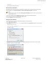
1
| Introduction | 2
© 2007-2014
Confidential and Proprietary
Property of iCRco, Inc.
Page 2 of 86
Doc # HC-CLS-0019-09 Rev I
January 10, 2014
| Contents | 3
Contents
Copyright and Proprietary Notice................................................................................................ 5
Contact and Product Information.................................................................................................7
Safety Information.......................................................................................................................... 9
iCRco Warranty............................................................................................................................ 11
Revision History............................................................................................................................ 15
Chapter 1: Introduction.........................................................................................17
Overview............................................................................................................................................................. 17
Chapter 2: Setup and Configuration....................................................................19
Local System Configuration...............................................................................................................................19
Updates................................................................................................................................................................19
Launching the Clarity Viewer............................................................................................................................ 19
Logging In...........................................................................................................................................................21
Tips...................................................................................................................................................................... 22
Preferences.......................................................................................................................................................... 23
Warning Lights....................................................................................................................................................35
Logging Out & Quitting.....................................................................................................................................36
Chapter 3: Operation and Usage.......................................................................... 37
Workflow Controls..............................................................................................................................................37
Search.................................................................................................................................................................. 38
Work List............................................................................................................................................................ 40
Prefetch Configuration........................................................................................................................................41
Image Layout and Navigation............................................................................................................................ 44
Image Manipulation Functions........................................................................................................................... 47
Cine Tools........................................................................................................................................................... 49
Rotate Tools........................................................................................................................................................ 51
Measurements......................................................................................................................................................52
Annotations......................................................................................................................................................... 54
Filters...................................................................................................................................................................56
Reporting Tools...................................................................................................................................................56
Advanced Tools.................................................................................................................................................. 59
Pelvic Toolset..........................................................................................................................................59
Other Tools..............................................................................................................................................63
Burning a CD/DVD............................................................................................................................................67
Saving and Sending a Study.............................................................................................................................. 68
Clarity Viewer Hotkeys...................................................................................................................................... 69
Chapter 4: DICOM Printing.................................................................................71
Advanced DICOM Printer..................................................................................................................................71
Printing to a Paper Printer..................................................................................................................................76
DICOM Print Troubleshooting for Windows.....................................................................................................81
Configuring a Printer with the QPC Print Tool................................................................................................. 82
Clearing the Java Cache.............................................................................................................. 83
Setting the Display Back to Default Using Regedit................................................................... 85
© 2007-2014
Confidential and Proprietary
Property of iCRco, Inc.
Page 3 of 86
Doc # HC-CLS-0019-09 Rev I
January 10, 2014
| Contents | 4
© 2007-2014
Confidential and Proprietary
Property of iCRco, Inc.
Page 4 of 86
Doc # HC-CLS-0019-09 Rev I
January 10, 2014
Copyright and Proprietary Notice
Proprietary Notice and Disclaimer
The information herein disclosed is the property of iCRco., Inc. Information in this document is subject to change
without notice and does not represent a commitment by iCRco to incorporate changes or improvements in units
previously sold or shipped. No part of this document may be reproduced or transmitted in any form, electronic or
mechanical, including photocopying and recording, for any purpose other than the purchaser's own use without the
express written permission of iCRco.
Copyright
Copyright© iCRco Inc. 2003-2013. All rights reserved.
Trademarks
iCR 1000™, iCR 1000 Dual™, iCR 2600™, iCR 2600 Dual™, iCR 2600SF™, iCR Vet™, iCR Vet Dual™, iCR
Mobile™, iCR 1-D™, iCR Chiro™, iCR Chiro Dual™, iCR 3600™, iCR 3600SF™, iCR VERTX™, iDR™, Fusion
DCR™, Chrome™, Chrome Duo™, Air DR™, Fusion DR Mobile™, QPC XSCAN32™, Captera™, XC™, and
www.icrco.com are the trademarks of iCRco. All other trademarks are the property of their respective owners, and
are hereby acknowledged.
Terms
Any one of the following iCR products will be referred to as the "CR unit" throughout this document: iCR Vet™, iCR
Vet Dual™, iCR Mobile™, iCR 1-D™, iCR Chiro™, iCR Chiro Dual™, iCR 3600™, iCR 3600SF™, iCR VERTX™,
iCR Fusion™, Chrome™, Chrome Duo™
Any one of the following iCR products will be referred to as "iCR desktop unit" throughout this document: iCR
VERTX™. The iDR™ and Fusion DR Mobile™ will be referred to as the "DR unit" throughout this document.
© 2007-2014
Confidential and Proprietary
Property of iCRco, Inc.
Page 5 of 86
Doc # HC-CLS-0019-09 Rev I
January 10, 2014
| Copyright and Proprietary Notice | 6
© 2007-2014
Confidential and Proprietary
Property of iCRco, Inc.
Page 6 of 86
Doc # HC-CLS-0019-09 Rev I
January 10, 2014
Contact and Product Information
Contact Information
iCRco., Inc.
Americas
Address:
2580 West 237th Street, Torrance, CA, 90505
Phone:
+1.310.921.9559
Fax:
+1.310.542.7236
Email:
[email protected]
Web:
http://www.icrco.com
iCRco., Inc.
Europe
Address:
Paderborner Str. 21, 44143 Dortmund, Germany
Phone:
+49.231.92733669
iCRco., Inc.
Middle East/India
Address:
1st Floor, Manohar Varsha, Y-7, Green Park (Main),
New Delhi-110016
Phone:
+011-40522979
Information
Please enter the details of the system here:
Serial Number:
Date Purchased:
Interface Type:
© 2007-2014
Confidential and Proprietary
Property of iCRco, Inc.
USB 2.0
Page 7 of 86
Doc # HC-CLS-0019-09 Rev I
January 10, 2014
| Contact and Product Information | 8
© 2007-2014
Confidential and Proprietary
Property of iCRco, Inc.
Page 8 of 86
Doc # HC-CLS-0019-09 Rev I
January 10, 2014
Safety Information
Read and understand the installation and operating instructions before starting the software.
Conventions
Warning:
A WARNING indicates a potentially hazardous situation which, if not avoided, could result in death or
serious injury.
Caution:
A CAUTION indicates a potentially hazardous situation which, if not avoided, may result in minor or
moderate injury. It may also be used to alert against unsafe practices.
Note:
A NOTE indicates important information that helps you better utilize your CR Unit and Software.
Important:
An IMPORTANT indicates either potential damage to hardware or loss of data and tells you how to avoid the
problem.
Malfunctioning Equipment
If any iCRco software product shows signs of malfunction, try restarting the computer; if the problem persists or is
reproducible discontinue the use of the product immediately and contact Technical Support at 310-921-9559.
Mammography
Access to Clarity Viewer's mammography feature is controlled by the USB Dongle Key.
Clarity PACS
Clarity Viewer is a component of the 510(k) cleared Clarity PACS (K002911).
Indications for Use
Clarity Viewer is software that retrieves digital images and data from various sources (e.g. CT scanners, MR scanners,
ultrasound systems, RIF Units, computed & direct radiographic devices, secondary capture devices, scanners, imaging
gateways, or other imaging sources).
Images (including mammography) and data can be retrieved and displayed within the system and/or across computer
networks at distributed locations.
© 2007-2014
Confidential and Proprietary
Property of iCRco, Inc.
Page 9 of 86
Doc # HC-CLS-0019-09 Rev I
January 10, 2014
| Safety Information | 10
Clarity's archiving engine utilizes lossless algorithms for compression services (JLSL, J2KR, and JPLL). Lossless
compressed mammographic images can be reviewed for primary image interpretation. Lossy compressed
mammographic images received from outside sources and digitized film screen images must not be reviewed for
primary image interpretation.
Mammographic images may only be interpreted using an FDA cleared monitor that offers at least 5 MP resolution
and meets other technical specifications reviewed and accepted by FDA.
© 2007-2014
Confidential and Proprietary
Property of iCRco, Inc.
Page 10 of 86
Doc # HC-CLS-0019-09 Rev I
January 10, 2014
iCRco Warranty
iCRco, Inc. ("iCRco") values your business and always strives to provide high-quality products and services. All
iCRco products are provided with an initial warranty so that the hardware and software are covered from the date
of purchase. This limited warranty solely applies to new products manufactured by or for iCRco and originally
purchased from iCRco or an authorized dealer of iCRco products for your own use. In addition, an extended warranty
is available for most new and recently purchased iCRco products for an additional charge.
Hardware Limited Warranty
iCRco warrants its hardware products to be free of defects in materials and workmanship for a period of one (1) year
from the date of original shipment from iCRco subject to the limitations set forth herein. If a product proves to be
defective in material or workmanship during the warranty period, iCRco will, at its sole option, repair or replace the
product with a similar product. Repaired and replacement products may be or include refurbished or remanufactured
parts. Any replacement item assumes the remaining warranty period of the original product. iCRco provides no
warranty for any third party hardware or software included with any product or later acquired.
Software Limited Warranty/Support
iCRco warrants that its QPC XSCAN32, Captera, XC, and/or Clarity PACS software originally provided with
any product will substantially conform to iCRco's specifications and that the media, not including hard drives, on
which the software is furnished will be free from defects in materials and workmanship under normal use for a
period of one (1) year from the date of original shipment from iCRco. iCRco's sole obligation under this warranty
is limited to making reasonable efforts to ensure such conformity and to supply the consumer with a corrected
version of the software as soon as it is practical after the consumer has notified iCRco of any nonconformity. iCRco
does not warrant that the operation of any software will be uninterruptible, glitch- or error-free, or that functions
contained in the software will operate in the combinations which may be selected for use by the user or meet the
user's requirements. This limited software warranty will be void if the software is modified without the written
approval of iCRco or is used outside of the recommended parameters or equipment. iCRco does not provide any
warranty or support for any other software.
iCRco agrees to provide one (1) year of telephonic and/or e-mail-based support for QPC XSCAN32, Captera, XC,
and/or Clarity PACS software originally provided with any new iCRco product from the date of original shipment
from iCRco . All software support shall be limited to making reasonable efforts to resolve iCRco software issues
and shall be limited to iCRco's regular business hours. In addition, iCRco will provide revisions and upgrades to its
software upon request (when available) during the first year after the software was originally shipped from the iCRco
factory. The initial support period will include support via remote login software, only if the customer has access to
the Internet from that PC and only if the customer agrees iCRco shall have no liability in connection with its support
efforts. Remote login software allows iCRco technical support to remotely access the customer's PC via the Internet
for the purposes of rendering technical support. Please note that this warranty, including software support, does not
include computer hardware, third party software, or operating system or network issues, which are outside the control
of iCRco.
Warranty Product Technical Requirements
iCRco requires that all DR, CR, Scanner, and/or products requiring PCs be fitted and installed with a 1300VA
(780W) uninterruptible power supply ("UPS"). iCRco recommends the APC 1300 specification UPS or equivalent.
For warranty evaluation and service, iCRco requires the customer to provide an Internet connection (DSL or Dialup) or the minimum of a phone line accessible by an extension cord to the product enabling iCRco technicians to
perform remote diagnostics on installed equipment. In addition, each iCRco product must be installed, maintained,
and operated in accordance with the respective product manual. Failure to comply with these requirements will result
in a voided warranty claim.
© 2007-2014
Confidential and Proprietary
Property of iCRco, Inc.
Page 11 of 86
Doc # HC-CLS-0019-09 Rev I
January 10, 2014
| iCRco Warranty | 12
Requesting Warranty Service
For information on obtaining warranty service, call iCRco's customer support at (310) 921-9559. In order to evaluate
a warranty service request, iCRco requires the following information: the iCRco serial number of the product,
a detailed description of the problem, customer name and contact information, product location and operating
conditions, a copy of the purchase documents, and sufficient information and authorization, including a liability
release as to any loss of data (that should always be backed up), software or network injury, or downtime, allowing
iCRco technicians remote access to the product. Product may not be returned to iCRco without first obtaining a
Return Material Authorization ("RMA") number from iCRco . Prior to providing an RMA, iCRco may require remote
access to the product. If iCRco determines that the product may be defective, is under warranty, and necessitates a
return to iCRco for service, an RMA number and instructions for return of the product will be given. iCRco is not
responsible for any unauthorized returned product, i.e. one for which an RMA number has not been issued by iCRco.
Warranty service requires all authorized returns be shipped to the iCRco factory prepaid and insured. All such
authorized returns are the customer's responsibility. For products sold and located within the United States, iCRco will
pay for return shipping.
Products being returned are only to be shipped in iCRco approved shipping containers. The original box and
packaging materials are approved and should be kept for moving and/or shipping the product. Approved packaging
may also be purchased from iCRco for an additional charge. iCRco shall have no liability nor responsibility for
warranty service to any product that is not shipped in an iCRco approved shipping container, that is damaged from
incorrect packaging, or that is damaged during shipping.
Additional Warranty Limitations and Extent of Warranty
This warranty does not apply if the product has been damaged by accident, misuse, or abuse. In addition, warranty
service does not include the repair of failures or defects caused by: unauthorized attachments to any iCRco product,
unsuitable physical or operating environment, maintenance or repair by anyone other than iCRco or the iCRco
authorized dealer that sold the product, operation of a product beyond its duty cycle, use of the product outside of its
specifications, the use of supplies, parts, materials, software, or interfaces not furnished, authorized, or recommended
by iCRco . If the product, including any software has been opened, tampered with, modified, or altered in any way
without written authorization by iCRco, the warranty will no longer apply.
This warranty applies only to products manufactured by, or for, iCRco; products can be identified by an "iCRco"
serial number as originally affixed to the product. Any modification to the iCRco serial number tag or its attachment
to the product shall immediately void the warranty.
This warranty is non-transferable and subsequent owners must contact iCRco to establish if the equipment is eligible
for an extended warranty.
THERE ARE NO WARRANTIES, EXPRESS OR IMPLIED, WITH RESPECT TO ANY iCRco PRODUCT
OTHER THAN AS SPECIFICALLY SET FORTH HEREIN, AND iCRco SPECIFICALLY DISCLAIMS ANY
IMPLIED WARRANTIES OR CONDITIONS OF MERCHANT ABILITY, FITNESS FOR A PARTICULAR
PURPOSE, AND SATISFACTORY QUALITY. ANY WARRANTIES THAT MAY NOT BE DISCLAIMED
UNDER APPLICABLE LAW ARE LIMITED IN DURATION TO THE INITIAL WARRANTY PERIOD AND
NO WARRANTIES, EXPRESS OR IMPLIED, WILL APPLY AFTER THIS PERIOD. ALL INFORMATION,
SPECIFICATIONS, PRICES, AND SERVICES ARE SUBJECT TO CHANGE AT ANY TIME WITHOUT
NOTICE.
Limitation of Remedies and Liability/Exclusion of Damages
The exclusive remedy for any defective product is limited to the repair or replacement of the defective product. iCRco
shall have a reasonable time after determining that a defective product exists to repair or replace a defective product.
iCRco's entire liability for any product is limited to the actual purchase price for the product. This limitation applies
even if iCRco cannot or does not repair or replace any defective product.
IN NO EVENT WILL iCRco BE LIABLE FOR ANY GENERAL, SPECIAL, CONSEQUENTIAL, OR
INCIDENTAL DAMAGES, including but not limited to, damages related to the loss of use, loss of recorded product,
the installation of replacement product, or any inspection, testing, or redesign caused by defect or by the repair or
replacement of any product arising from a defect in any product. This exclusion of damages applies even if the
© 2007-2014
Confidential and Proprietary
Property of iCRco, Inc.
Page 12 of 86
Doc # HC-CLS-0019-09 Rev I
January 10, 2014
| iCRco Warranty | 13
customer advises iCRco or an iCRco dealer of the possibility of such damages. This limitation of remedies also
applies to claims against any suppliers or dealers of iCRco. iCRco and its suppliers' and dealers' limitations of
remedies are not cumulative. Such suppliers and dealers are intended beneficiaries of this limitation. iCRco is not
liable for any claim by or against the customer arising from a third party claim.
© 2007-2014
Confidential and Proprietary
Property of iCRco, Inc.
Page 13 of 86
Doc # HC-CLS-0019-09 Rev I
January 10, 2014
| iCRco Warranty | 14
© 2007-2014
Confidential and Proprietary
Property of iCRco, Inc.
Page 14 of 86
Doc # HC-CLS-0019-09 Rev I
January 10, 2014
Revision History
Revision
Date
Approved by
Comments
A
2009-04-06
MS
Initial release
B
2010-03-03
MS
Updated with 1.3 features
C
2010-07-08
MS
Added CE and FDA
approval label
D
2010-10-05
MS
Updated with 1.4 features
E
2011-03-09
MS
Updated minimum
computer requirements
F
2013-05-23
KS
Updated for 4.8 Release
F-02
2013-07-30
KS
Frontmatter Update
G
2013-07-31
KS
Updated for 4.10 Release
H
2013-12-20
KS
Feature Clarification
I
2014-01-10
KS
Updated for 4.12 Release
© 2007-2014
Confidential and Proprietary
Property of iCRco, Inc.
Page 15 of 86
Doc # HC-CLS-0019-09 Rev I
January 10, 2014
| Revision History | 16
© 2007-2014
Confidential and Proprietary
Property of iCRco, Inc.
Page 16 of 86
Doc # HC-CLS-0019-09 Rev I
January 10, 2014
Chapter
1
Introduction
Overview
Clarity is an easy to maintain, scalable, digital image, and information management solution. Clarity provides a
secure, HIPAA-compliant image management and display for medical imaging modalities including: Computed
Radiography (CR), Magnetic Resonance (MR), Computed Tomography (CT), and Ultrasound (US). The Clarity
Archive provides DICOM services including DICOM storage, DICOM routing, and DICOM Modality Work List for
patient information systems. The Clarity Archive also includes integration with most existing RIS and HIS systems.
The Clarity Archive supports the HL-7 protocol allowing integration with many EMR systems.
The Clarity Viewer is a multi-modality image viewer designed to provide rapid and easy access to medical images.
Multiple monitors are automatically detected and easily configured. An integrated Work List provides flexible search
options such as filtering by patient ID, accession number, study ID, modality, study status, and many more. The
Clarity Viewer provides robust and easy-to-use image manipulation and annotation tools including support for CR,
DR, and cross-sectional imaging (e.g., US, CT & MR modalities).
© 2007-2014
Confidential and Proprietary
Property of iCRco, Inc.
Page 17 of 86
Doc # HC-CLS-0019-09 Rev I
January 10, 2014
| Introduction | 18
© 2007-2014
Confidential and Proprietary
Property of iCRco, Inc.
Page 18 of 86
Doc # HC-CLS-0019-09 Rev I
January 10, 2014
Chapter
2
Setup and Configuration
Local System Configuration
Minimum Viewing Workstation Configuration:
CPU: 2 GHz Core2Duo
System RAM: 4 GB (6 GB for non-CR diagnostic review)
Hard Drive: 200 GB
Graphics Card: 1280 x 1024/32-bit color capable graphics card
Monitor: High-contrast diagnostic quality monitor (two monitors recommended)
Operating System: Windows 7 Service Pack 1, 64-Bit
Java: Version 6 Update 14
Domain Configuration:
Note:
The User may access Clarity Viewer using a domain name, but the network must be properly configured.
Please contact your system administrator to assign a domain name to the Clarity Viewer. Any Workstations
wishing to access the Clarity Viewer via a domain name must be configured on the same Windows domain as
the Archive. Domain misconfiguration may result in a non-functioning Clarity Viewer.
Firewall Configuration:
Workstations wishing to use the Clarity Viewer or DICOM Send and Query/Retrieve to the Clarity Archive need to
have TCP ports 104 (DICOM), 8443 (Clarity launch page SSL port), and 11112 (Clarity Archive port) and UDP port
137 (data transfer) open in the Windows firewall and any third party hard and/or software firewalls running on the
network.
Updates
When a new version of the Clarity Viewer has been deployed to the Clarity server, the Clarity Viewer software will
automatically update itself from the Clarity server onto the Workstation on the next launch.
Launching the Clarity Viewer
Initial Installation and Launch of Clarity Viewer
1. Launch the web browser.
2. In the address bar, enter https://IPADDRESS:8443/icrco-viewer where
© 2007-2014
Confidential and Proprietary
Property of iCRco, Inc.
Page 19 of 86
Doc # HC-CLS-0019-09 Rev I
January 10, 2014
| Setup and Configuration | 20
IPADDRESS
is the IP address of the Clarity Archive.
Note:
It is recommended that the user register a domain name for the Clarity server and purchase an SSL
certificate from a trusted Certificate Authority when using remote viewing. These actions help ensure
secure data transmission.
Note:
If accessing Clarity through a secure local area network or VPN, the user can enter http://
IPADDRESS:8080/icrco-viewer instead of the "https" address. This allows to user to avoid the
browser security warning dialog.
3. Click the Launch link to start the Clarity Viewer.
4. The dialog box Opening launch.jnlp will appear. Make sure the Open with radio dialog is selected and the
drop-down box next to it says:
Java Web Start Launcher
Click OK to continue.
Note:
You will have to click Continue when asked if you trust the Clarity website.
5. Depending on the version of Clarity, a Java Security Warning might appear asking if the user wants to run the
application. Check the box and select Run.
6. The Clarity Viewer will open and display a login dialog.
Note:
This process will only need to occur once on each workstation. After the initial installation of the Viewer,
a shortcut will be placed on the desktop.
© 2007-2014
Confidential and Proprietary
Property of iCRco, Inc.
Page 20 of 86
Doc # HC-CLS-0019-09 Rev I
January 10, 2014
| Setup and Configuration | 21
Quick Launch of Clarity Viewer
After the initial installation of the Clarity Viewer, a shortcut to the application is placed on the User's desktop. To
launch the Clarity Viewer, simply double mouse click on the desktop shortcut.
Logging In
After launching, the Clarity Viewer will open and present a login dialog box. Enter a User name and password, then
click OK to continue.
Note:
The default username and password is "user" and "user".
Note:
If you do not have a User name and password, please contact your System Administrator.
LDAP Authentication
If the Clarity Archive is set up with LDAP (Lightweight Directory Access Protocol), then check the LDAP
Auenthication box.
LDAP is used to allow user to have a single login account across multiple applications, commonly known as SSO
(Single Sign-On). SSO integration with certain systems might require further configuration of Clarity. Contact iCRco
for more information.
Clarity Server Selection
The login screen allows you to select which Clarity Archive you wish to access. This is useful if you have more than
one Archive that you regularly use.
To add a new Archive to the list, click the drop-down arrow on the right side of the Server field. Select Add Server.
© 2007-2014
Confidential and Proprietary
Property of iCRco, Inc.
Page 21 of 86
Doc # HC-CLS-0019-09 Rev I
January 10, 2014
| Setup and Configuration | 22
This will bring up the Add Server dialogue box.
You may enter in the Clarity Archive information including server address and the name you want displayed in the
Login panel. It it possible to set the new archive as the default server listed when the Login dialogue appears. Simply
check the default server box.
Click OK.
Note:
Upon logging in, the server you're currently connected to will be shown underneath the Clarity logo.
Tips
The Clarity Viewer will display a Tip of the Day when the application is started. The Tip of the Day gives the User
helpful information to make using the Clarity Viewer easier.
The User can use the Previous Tip & Next Tip to display more tips.
© 2007-2014
Confidential and Proprietary
Property of iCRco, Inc.
Page 22 of 86
Doc # HC-CLS-0019-09 Rev I
January 10, 2014
| Setup and Configuration | 23
The Close button will close the Tip of the Day dialog box.
The User can disable the Tip of the Day by unchecking the Show Tips on Startup box.
To re-enable the Tip of the Day, see Section Show Help Tips on page 23.
Preferences
The preferences can be accessed by clicking on the Configuration button, located in the upper, right-hand corner of
the Work List window. Clicking the Configuration button will cause the Preferences dialog to pop-up.
Connection
The Connection Tab in Preferences control the various settings related to digital communication between the Viewer
and Archive. The user can control timeout, server selection, and help tip settings in this tab.
Show Help Tips
Clicking the Show Help Tips button will bring up the Tip of the Day window. Here the user can view the various tips
or enable/disable the feature by checking or unchecking the Show tips on startup box.
Inactive Timeout
The Inactive Timeout preference allows the User to specify the length of time before the Clarity Viewer automatically
logs out. To modify the Inactive Timeout preferences, click the Connection tab in the Preferences dialog. Select the
desired length of time. The default duration is 20 minutes.
DICOM Send Timeout
The user can set how long Clarity PACS will attempt to DICOM Send a study to an Archive, before stopping due to
timeout.
Servers Field
The Servers field lists the Clarity Archive servers currently registered on the view station. From this screen, a user can
add, edit, or delete an archive from the list.
Default Server
The user can select which archive is the default server from the dropdown menu.
© 2007-2014
Confidential and Proprietary
Property of iCRco, Inc.
Page 23 of 86
Doc # HC-CLS-0019-09 Rev I
January 10, 2014
| Setup and Configuration | 24
Monitor Configuration Options
The monitor preferences can be accessed by clicking on the Configuration button. This will bring up the Preferences
dialog. From there, click the Monitor tab.
From the Preferences dialog, the User can configure each monitor attached to the computer. The monitors are
numbered according to their Windows device configuration.
Note:
Changing monitor preferences will require a restart of the Clarity Viewer for the changes to take effect. The
application will not restart on its own. The User will need to restart the application manually.
Work List on Monitor
The User may select which monitor the Clarity Viewer displays the Work List on. This is achieved by selecting the
radio dialog check box to the left of the desired monitor. Click the Apply button to save the changes, then restart the
Clarity Viewer for the changes to take effect.
Monitor Configuration
The steps to configure a monitor are as follows:
1.
2.
3.
4.
Select the desired monitor from the monitor selection box.
If the monitor is not enabled, check the Monitor Enabled box.
Select if the monitor is Color or Monochrome (the default is color).
Click Apply. Quit and relaunch the Clarity Viewer for the changes to take effect.
Lock Worklist
This feature allows the User to select a specific monitor on which he wants to see the worklist. It makes the worklist
always appear at the selected monitor. For enabling this feature, the circular box against Worklist on Monitor needs
to be checked. For example, if the User wants to see the worklist on 1st monitor then he should check the circular box
against monitor 1.
Hide Windows Tool bar
The User can choose whether to show or hide the Windows tool bar by checking or unchecking the preference
check box. The check box is located directly below the monitor selection box. Selecting the check box will hide the
Windows tool bar. If this check box is not selected, then the Windows tool bar will be displayed.
© 2007-2014
Confidential and Proprietary
Property of iCRco, Inc.
Page 24 of 86
Doc # HC-CLS-0019-09 Rev I
January 10, 2014
| Setup and Configuration | 25
Default Display Layout Per Monitor
The User can choose, on a per modality basis, how series of images are laid out on screen. If the Fit All Series box is
checked, the Clarity Viewer will display every series from the selected patient on the screen. If the Fit All Series box
is not checked, the user may choose the maximum number of rows and columns of series of images to display.
Reporting
The Reporting preferences can be accessed by clicking on the Configuration button. This will bring up the
Preferences dialog. From there, click the Reporting tab.
Reporting Doctors Name
In the Report Writer tab, the User may set the name of the physician that will appear in the report.
Note:
This is a per User setting. Each User can have his or her own name to appear in the report. Only Users with
the user privileges of "doctor" can write reports. Please see the Clarity Configuration & Troubleshooting
Manual for more information on creating new users and setting user privileges.
Study Status Update When Closing Study
When this option is checked, upon closing an image from the Viewer, a dialog box will appear asking the User to
update the Study Status:
Figure 1: The Update Study Status dialog pops-up after closing a study in the Viewer window.
This option works in conjunction with the Filter Modifiers and Study Status workflow options present in the Work
List window.
Options
Update and Close: Updates the study status to the selected value, e.g. "Read", then close the study.
© 2007-2014
Confidential and Proprietary
Property of iCRco, Inc.
Page 25 of 86
Doc # HC-CLS-0019-09 Rev I
January 10, 2014
| Setup and Configuration | 26
Close Only: Closes the study without changing the study status.
If a report is written with the option enabled, upon clicking the Create button, the report will be generated, the current
patient will close, the study status will be set to Validated and the next patient in the worklist will be selected.
Notify if all studies have not been viewed
When this option is checked, if all images in the study have not been viewed, the Clarity Viewer will display a
warning dialog notifying the User.
Report Font Type
The User may configure the body text font face used when writing reports in the Clarity Viewer. Select the desired
font from the drop-down menu. Click the Apply button to save the changes.
Report Fonts Size
The User may configure the body text font size used when writing reports in the Clarity Viewer. Select the desired
font size from the drop-down menu. Click the Apply button to save the changes.
Report Header Font Size
The User may configure the header text font size used when writing reports in the Clarity Viewer. Select the desired
font size from the drop-down menu. Click the Apply button to save the changes.
Report Confidentiality Font Size
The User may configure the Report Confidentiality text font size used when writing reports in the Clarity Viewer.
Select the desired font size from the drop-down menu. Click the Apply button to save the changes.
Report Site Label Font Size
The User may configure the Report Site Label text font size used when writing reports in the Clarity Viewer. Select
the desired font size from the drop-down menu. Click the Apply button to save the changes.
Report Site
Report Icon
Clicking the Choose Icon button will allow the User to select a JPEG, GIF, or PNG file of the practice or site logo
to be placed in the report header. Clicking the Choose Icon button will bring up a file upload dialog from which the
User may select the site logo. After selecting the desired graphic, click the Save button to save the icon. The Clear
Icon button removes the current icon, allowing for the upload of a new icon.
© 2007-2014
Confidential and Proprietary
Property of iCRco, Inc.
Page 26 of 86
Doc # HC-CLS-0019-09 Rev I
January 10, 2014
| Setup and Configuration | 27
Current Icon
Displays a preview of the current icon that is displayed in the Report header.
Site Name
Enter the Site or Practice name in the text field.
Site Address
Enter the Site or Practice address in the text field.
Phone Number
Enter the Site or Practice phone number in the text field.
Fax
Enter the Site or Practice fax number in the text field.
URL
Enter the Site or Practice website address in the text field. For example: http://www.icrcompany.com
Confidentiality Agreement
Enter the Site or Practice confidentiality agreement text in the text field.
Report Body Elements
The Report Body Elements allows the User to customize the elements in a Report. Each element can only appear
once in a report (an element is Impressions, Findings, Procedure Description, Conclusions, etc.) Select the number
of elements to appear in a report in the Number of Report Body Elements box, then select the heading for each
element (For example, Impressions, Findings, Conclusions, etc).
Text Expansion
This feature facilitates the User to set a Key Text and its Expansion Text. The advantage of this feature is that
the User just has to type the Key Text while writing a patient report and the application automatically pulls up its
Expansion Text.
To use this feature, see the following steps:
1. Type a Key Text against the Add Key button and click Add Key.
2. The Key Text just added gets displayed under Key Text.
3. Select this Key Text and click in the box provided under Expansion Text
© 2007-2014
Confidential and Proprietary
Property of iCRco, Inc.
Page 27 of 86
Doc # HC-CLS-0019-09 Rev I
January 10, 2014
| Setup and Configuration | 28
4.
5.
6.
7.
Type in the details for the Key Text and click Save Key.
Select a Key Text and click Remove Key to delete the Key Text.
Click Apply and restart the Clarity Viewer to make the changes effective.
To use this feature:
1.
2.
3.
4.
5.
Select a patient from the worklist and open any image.
Click the Reports button on the left panel and the click Write Report.
Type the Key Text wherever you want the Expansion Text.
Press Shift Key + Space Bar.
The Key Text will be converted into Expansion Text
Annotation Options
The Annotation Options allow the User to set the font, font color and size, annotation line thickness, and annotation
color. The User may apply these options to all annotations at once (by selecting All from the Annotation Type dropdown menu), or the User may select the type of annotation, and set the parameters individually for each annotation
type.
Annotation Type
Using the Annotation Type drop-down menu allows the User to select configuration parameters for each individual
annotation tool, or set the parameters for all tools at once (select All in the Annotation Type drop-down menu).
Annotation Font Type
Allows the User to select any font installed on the operating system to display annotations using text.
Annotation Font Size
Allows the User to select the font size for annotations using text. The User may choose a font size between eight (8)
and twenty (20) points.
Annotation Line Thickness
Allows the User to select a value between one-half (0.5) and four (4.0) for the thickness of the annotation lines.
Annotation Color
Allows the User to select the color for the annotation lines and text. The User may select from swatches (commonly
used, pre-defined colors) by clicking on a swatch color, HSB (Hue, Saturation, and Brightness) by selecting a point
somewhere in the colored square, or RGB (Red, Green, and Blue) by adjusting the sliders to the desired result.
© 2007-2014
Confidential and Proprietary
Property of iCRco, Inc.
Page 28 of 86
Doc # HC-CLS-0019-09 Rev I
January 10, 2014
| Setup and Configuration | 29
Preview
The Preview box will preview the selected colors, so the User may see how it looks before saving the preferences.
Curve Tool
The user can set the radius for the reference curves used in the Curve tool. The radius can be selected for the C1 T1 Cervical Curve (C1), the C2 - C7 Cervical Curve (C2), and the Lumbar Curve (L). To set the radius, click the
corresponding box and type in the desired radius in millimeters.
The Display dropdown box allows you to select whether you want the Curve Tool to display the curve's angle
measurement, the curve's radius measurement, or both measurements.
Note:
The Curve Tool is part of the Advanced Tools. This setting will be greyed out if the Advanced Tools feature is
not activated on the dongle license.
Warn before clearing annotations
When this box is checked, Clarity will notify the user before annotations are removed.
Start text arrow on click
When this box is unchecked, drawing an arrow annotation begins with the end of the arrow. When the box is checked,
drawing an arrow annotation begins with the arrow head.
Show cross-section projetions by default
When this box is checked, the cross-reference lines will automatically appear when viewing images.
Cobb angle indicator
The user may select whether the Cobb angle uses lines, an arc, or neither.
Angle arc
The user can choose which angle is measured when selecting three points. If the first point setting is chosen, then the
angle will measure the angle where the first point is the vertex. If the second point setting is chosen, then the angle
will measure the angle where the second point is the vertex.
Annotation unit
The user may choose the unit of measurement.
Flash Mammo CAD Markers
If the box is checked, mammography images will flash the CAD markers on the image when it is loaded.
Show measurement backgrounds
When this box is checked, the measurements will be displayed in a small, white bubble field.
Show Measure Distance dashed lines
When checked, the measured distance will be indicated with a dashed line. When unchecked, only the measurement
will be displayed.
© 2007-2014
Confidential and Proprietary
Property of iCRco, Inc.
Page 29 of 86
Doc # HC-CLS-0019-09 Rev I
January 10, 2014
| Setup and Configuration | 30
Angle precision
The angle precision drop-down menu allows you to select how many digits past the decimial point to display in an
angle measurement. For example, if an angle measured 141.59°, Clarity will display:
•
•
•
0 Digits - 142°
1 Digit - 141.6°
2 Digits - 141.59°
Predefined Labels
This tool allows you to set up predefined labels, which can be placed on an image using the Advanced Tools.
To add a label, select a folder and click the Add Child button. Type in the label text and click OK.
Note:
To create a new folder, click the Add Child button. Name the label. Then add a child to the label you just
created. This will convert the label to a folder.
To remove a label or folder, select the item and click Remove.
Note:
Removing a folder will delete the folder and all labels within it.
To edit the name of a label or folder, select the item and click Edit.
It is possible to reorder the predefined label list by using the up and down buttons. Select the item you wish to move,
then click either button to move it.
Note:
If you click within the grey testing area, you can see what the predefined label menu will look like.
Note:
Predefined Labels is part of the Advanced Tools. This setting will be greyed out if the Advanced Tools feature
is not activated on the dongle license.
Language Options
The Language options can be accessed by clicking on the Configuration button. This will bring up the Preferences
dialog. From there, click the Language tab.
Locale
Setting the locale will set the language, text orientation (left to right or right to left), and date & time for the given
region. Currently supported locales are: Chinese, English, German, Hindi, Japanese, Portuguese, Serbian, Spanish,
and Thai.
© 2007-2014
Confidential and Proprietary
Property of iCRco, Inc.
Page 30 of 86
Doc # HC-CLS-0019-09 Rev I
January 10, 2014
| Setup and Configuration | 31
Font
The font option allows the User to select the font face for the application. This includes the font face for the Work
List and all dialog boxes inside the Clarity Viewer application, but does not include annotation fonts which are
set separately in the Annotations tab. See Section Annotations on page 54 for more information on setting
Annotation fonts.
Print Tool Language
The user may choose which language the QPC Print Tool uses.
Note:
It may be necessary to change the computer's locale in order for QPC Print Tool to properly display the
selected language.
Tools Options
The Tools options can be accessed by clicking on the Configuration button. This will bring up the Preferences
dialog. From there, click the Tools tab.
Center Line Options
The Center Line tool has four different drawing options. The options are: Two Points without Line, Two Points
with Line, Four Points, or Eight Points with Angle. Please see Section Center Line Options on page 31 for the
differences between each Center Line option.
Default Overlay Level
The user may select the amount of information displayed in the corner of the image.
•
•
•
None - No text is displayed.
Normal - Minimal text is displayed.
Full - A large amount of text is displayed.
Close tab button on left side of tab
If this box is checked, the close button "X" will be relocated to the left side of the tab.
Select Default Tools Per Modality
Selecting the default tools per modality allows the User to override the default mouse button mapping described
in Section Default Mouse Actions on page 44. First select the desired modality, then choose the desired mouse
© 2007-2014
Confidential and Proprietary
Property of iCRco, Inc.
Page 31 of 86
Doc # HC-CLS-0019-09 Rev I
January 10, 2014
| Setup and Configuration | 32
button mapping. For example, for the CT modality, the user may want to map Pan to the left mouse button, map
Zoom to the middle mouse button, map W/L to the right mouse button, and map Zoom again to the mouse wheel.
Favorite Tools
It is possible to choose which tools appear in the Favorite Tools section of the toolbar. There are five available slots in
the toolbar. Use the dropdown menu to select the desired tool. After the configuration has been applied, the selected
tools will appear in the toolbar.
Note:
This feature was formerly known as Frequently Used Tools.
License Information
This tab will display the software serial number, sales order number, number of modality inputs, number of LAN
and Web viewers, and enabled Clarity modules. This information is especially important when contacting Technical
Support.
Server
The server tab displays Clarity's server information. The data here cannot be modified.
Hanging Protocols
The Hanging Protocols tab allows the user to modify anatomy window/level presets and manage saved protocols.
© 2007-2014
Confidential and Proprietary
Property of iCRco, Inc.
Page 32 of 86
Doc # HC-CLS-0019-09 Rev I
January 10, 2014
| Setup and Configuration | 33
On the left side of the window, the user can set the presets for the window/level settings for each anatomy. The
specific value can be modified in each of the anatomy's fields.
On the right side of the window, Clarity displays all of the saved hanging protocols, providing information such as
description, anatomic region, and modality for each protocol. From this screen, the user may save protocols as a
DICOM file, allowing the user to transfer protocols to another Clarity server. It is also possible to DICOM Send the
Hanging Protocol settings or load existing hanging protocols from a DICOM file. If the user desires, a preset can be
deleted.
Advanced
The Advanced tab allows the users to select the desired representation for person names, auto-advanced worklist,
viewer logger level, image cache drive and percent confidence in memory prediction.
Desired Representation for Person Names
The person names can be written in three different characters. The user can select any representation out of SingleByte (which is default), Ideographic, and Phonetic to get the desired display of the person name.
Clarity Directory
The Clarity Directory setting allows the user to determine the location of the Clarity root directory. Changing the
directory will change where the cache files are saved. After switching to a new directory, restart Clarity.
Important:
Changing to a new directory will delete the cached files in the old directory.
© 2007-2014
Confidential and Proprietary
Property of iCRco, Inc.
Page 33 of 86
Doc # HC-CLS-0019-09 Rev I
January 10, 2014
| Setup and Configuration | 34
Note:
The default directory is C:\. If the permission settings on the computer do not allow data to be written to
the C Drive, then Clarity will use the APPDATA location. Clarity directories written to APPDATA can
be found under C:\Documents and Settings\[username]\Application Data\ICRCO on Windows XP and C:
\Users\[username]\AppData\Roaming\ICRCO on Windows 7. The APPDATA folder is hidden by default on
Windows.
Note:
The pre-fetch feature will only work with the C Drive.
Note:
Clarity Light Viewer will always use APPDATA and the directory cannot be changed.
Viewer Logger Level
The User can select the Viewer Logger Level as Debug, Info, Warn, Error, and Fatal. By default, Info is selected
and it means that the log report for Clarity viewer will include all the logger levels provided below the Info level
in the combo box. So, the log report shows all the levels below the selected level in the combo box including the
selected level itself in the log report. So, if the user selects Debug level, then all the levels will be shown in the log
report.
Percent Confidence in Memory Prediction
This option is set to 100 by default. To get more information on what it actually is, click on the button having (?) on it.
An Information Message box pops out giving the details about percent confidence in memory prediction.
Important:
It is highly recommended that this value remain at 100 percent. If necessary, the value should only be
modified by qualified personnel.
Percent of Disk Full before Deletion
Clarity automatically caches opened studies, eventually filling up the cache. In order to prevent the cache from filling
to capacity, the program will automatically trim older images.
The user can modify when Clarity will begin deleting older images and how much space it will try to free up.
It is possible to delete local preferences stored in the Windows registry such as monitor layout and user preferences.
© 2007-2014
Confidential and Proprietary
Property of iCRco, Inc.
Page 34 of 86
Doc # HC-CLS-0019-09 Rev I
January 10, 2014
| Setup and Configuration | 35
About Button
The About This Software dialog can be accessed by clicking on the Configuration button. This will bring up the
Preferences dialog. From there, click the About button on the top, right corner. The About button will pop-up the
End User License Agreement for the Clarity Viewer application.
Warning Lights
Clarity will display warning lights when the warranty is expiring, when the dongle license is expiring, and when the
disk storage is approaching maximum capacity.
It is possible to hide the warning lights by clicking the "X" to the right of the warnings. The lights will appear each
time Clarity starts.
Expired Warranty
When the user's warranty is about to expire, Clarity will notify the user the number of days until expiration. The
warning message is displayed at the top, left corner of the screen. To renew the warranty, call (310) 921-9559.
Note:
The warning message color will vary depending on the time until expiration.
•
•
•
Yellow - Will expire within 45 Days
Orange - Will expire within 30 Days
Red - Will expire within 14 Days and after expiration
License Expiration
The Clarity Viewer uses a dongle licensing verification system. When the user's license is about to expire, Clarity
will notify the user the number of days until expiration. The warning message is displayed at the top of the screen. To
update the dongle license, the user should contact the dealer or iCRco by calling (310) 921-9559.
Note:
The warning message color will vary depending on the time until expiration.
•
•
•
Yellow - Will expire within 45 Days
Orange - Will expire within 30 Days
Red - Will expire within 14 Days and after expiration
Disk Storage Space
When your Clarity Archive begins to approach maximum capacity, Clarity will display a warning message at the top
of the screen.
When the user receive this message, iCRco recommends that the user's Clarity PACS be upgraded. Call iCRco at
(310) 921-9559.
Note:
The warning message color will vary depending on how full the archive is.
•
•
•
Yellow - When the Archive is 90 percent full or greater
Orange - When the Archive is 93 percent full or greater
Red - When the Archive is 95 percent full or greater
© 2007-2014
Confidential and Proprietary
Property of iCRco, Inc.
Page 35 of 86
Doc # HC-CLS-0019-09 Rev I
January 10, 2014
| Setup and Configuration | 36
Logging Out & Quitting
button, located in the upper, right-hand corner of the Work
To log out of the Clarity Viewer, click the Log Out
List window. Logging out of the Viewer leaves the application open, but will require the User to enter a name and
password to be able to access data again.
To quit the Clarity Viewer, click the Quit
button, located in the lower, right-hand corner of the Work
List window. Quitting the Viewer means the User will have to re-open the application to access data again.
To minimize the Clarity Viewer, click the Minimize
button, located in the lower, right-hand corner of the Work
List window. Minimizing the Viewer allows the user to hide the Viewer without exiting the program. This can be
useful if the user needs to utilize other programs and doesn't want to quit out of Clarity.
© 2007-2014
Confidential and Proprietary
Property of iCRco, Inc.
Page 36 of 86
Doc # HC-CLS-0019-09 Rev I
January 10, 2014
Chapter
3
Operation and Usage
Workflow Controls
Note:
Workflow control buttons may appear grayed out a certain times. A grayed out Workflow button means
that the User may not use the button's function at the present time (e.g., when exporting images, the Clarity
Viewer can not be quit, thus the quit button is grayed out).
Work List
The Work List button
returns the User to the Work List window.
Viewer
The Viewer button
returns the User to the Image Viewing window.
Send/Save Study
From the Work List:
Clicking the Send Study button
with patient{s} selected in the Work List will bring up the DICOM
Send dialog. The user will need to click "Yes" when the program opens a dialog box asking if the user wants to
continue. From the DICOM Send dialog, the User may DICOM send the studies to a different target, and configure
new targets.
From the Image Viewing Window:
Clicking the Save Study button
while in the Viewer allows the User to save image manipulation
settings (sans Pan and Zoom settings) and annotations. The User may save multiple different sets of annotations on
the same image.
Write CD
The Write CD button
opens the dialog to export the selected studies and images to a CD/DVD. The
user will need to click "Yes" when the program opens a dialog box asking if the user wants to continue.
Print
The Print button
opens the current image(s) with the DICOM print application.
Quit
The Quit button
© 2007-2014
Confidential and Proprietary
Property of iCRco, Inc.
exits & closes the Clarity Viewer.
Page 37 of 86
Doc # HC-CLS-0019-09 Rev I
January 10, 2014
| Operation and Usage | 38
Minimize
The Minimize button
hides the Clarity window without exiting the viewer.
Search
Search Keys
The Search Keys, located in the upper, left-hand corner, allow the User to search by patient last name, patient ID,
accession number, or study ID. Select one of these from the Search By drop-down menu, and then enter the search
criteria in the Search For box below. As soon as the User begins typing, the results of the search will appear in the
Patient / Study Search Results Work List, located near the middle of the screen.
Search Filters
Search Filters are used in conjunction with Search Keys to help narrow the results of a search. The Search Filters can
filter by study status, modality, facility name, date, and/or referring physician.
Filter Presets
Filter Presets are user-defined, allowing the User to define an optimal workflow. The Filter Presets can be accessed in
a drop-down menu in the upper left part of the Search Filters box. Clicking the drop-down menu will reveal a list of
the default Search Filters.
Creating and Editing Filter Presets
The User can edit & define new Filter Presets by clicking on the Manage Filters button.
© 2007-2014
Confidential and Proprietary
Property of iCRco, Inc.
Page 38 of 86
Doc # HC-CLS-0019-09 Rev I
January 10, 2014
| Operation and Usage | 39
Note:
The default filters cannot be modified.
New Filter Preset:
1. From the Work List Window, click Manage Filters.
2. Enter the desired filter name in the Filter Name text box. Make sure the new name is not already entered as a
filter name.
3. Enter the desired filter criteria. The User does not have to fill in all filter criteria, e.g., if the User desired a filter
for all CR studies, then select the modality from the Modality drop-down menu, and select the date ranges.
4. Click the Save Filter button.
Editing a Filter Preset:
1. From the Work List Window, click Manage Filters.
2. Highlight the filter to edit in the Filter Order box.
Note:
Default filters cannot be edited.
3. Edit the desired Filter criteria.
4. Click the Save Filter button.
Show Stat Studies First
When the user checks this option, the filter will automatically reorder the studies so that studies marked as "stat" are
shown at the top of the list.
Note:
It is possible to mark a study as "stat" by right-clicking on the study in the worklist and selecting Change
Stat. To unmark a study, simply select Change Stat on the study once more.
Enable Date Range Filtering
This option directs the filter to only display studies within a specified date range.
© 2007-2014
Confidential and Proprietary
Property of iCRco, Inc.
Page 39 of 86
Doc # HC-CLS-0019-09 Rev I
January 10, 2014
| Operation and Usage | 40
Work List
Sorted Studies
Sorted Studies appear below the Search Keys & Filters. Sorted Studies show the studies that match the criteria
specified in the Search Keys & Filters.
Grouped Studies
Note:
The Grouped Studies work list will only appear with screen resolutions of 1280 x 1024 or above.
Grouped Studies appear below the Sorted Studies. The Grouped Studies show all the studies from a patient selected in
the Sorted Studies Work List.
Thumbnails
The thumbnail previews are shown at the bottom of the screen when a study is selected in either the Sorted Studies or
Grouped Studies Work List.
Status
The Status column uses colors to indicate the current loading state of the study.
•
•
•
•
Black - The image is located on the server.
Blue - The image is queued to be downloaded from the server.
Yellow - The image is currently downloading from the server.
Green - The image has been retrieved from the server and is stored in the cache. It can be viewed.
Note:
It is possible to query and retrieve multiple studies without opening them.
Viewing Selected Studies
From the Work List:
To view a selected study, the User may double click the desired study in the Sorted or Grouped Studies, or the User
may double click the preview thumbnail at the bottom of the Work List.
From the Image Viewer window:
© 2007-2014
Confidential and Proprietary
Property of iCRco, Inc.
Page 40 of 86
Doc # HC-CLS-0019-09 Rev I
January 10, 2014
| Operation and Usage | 41
To view a selected study, mouse over the bottom part of the window to reveal the thumbnails associated with the
study, then drag and drop the desired image into the image manipulation window and the image will load.
Lossless and Lossy Images
Clarity uses lossless algorithms for image compression. The software supports JPEG-LS Lossless (JLSL), JPEG
2000 Lossless (J2KR), and JPEG Lossless (JPLL) compression services. Lossless compressed images can be used for
primary image interpretation.
It is possible for Clarity to receive images from outside sources that were compressed using lossy compression
services. The software can accept JPEG Lossy (JPLY) images from other sources, but does not apply this compression
service. Lossy images may not be used for primary image interpretation.
The user may determine if a lossy compression service was used on an image by checking the DICOM tags. To check:
1. Open the image in the Viewer.
2. Press Ctrl + D on the keyboard. This will open a dialog box with the list of the image's associated DICOM tags.
3. Locate the DICOM tag labeled (0028,2110). This is the Lossy Image Compression tag.
Note:
If this tag does not exist, the image was not subjected to lossy compression.
4. If the tag exists, examine the tag's value. If the value is 00, then the image was not subjected to lossy compression.
If the value is 01, then the image was subjected to lossy compression and may not be used for primary image
interpretation.
Prefetch Configuration
Prefetch sets up Clarity so that it automatically downloads studies based on a specified criteria. This criteria can be set
and customized by the user.
The downloaded studies, because they are cached, will open quicker than studies that will have to be downloaded
when opened.
Prefetch Installation
Prefetch can only be installed by a qualified iCRco service engineer. Contact iCRco for assistance.
Accessing Prefetch
To access the Prefetch settings:
1. Launch a web browser.
2. In the address bar, enter https://IPADDRESS:8443/Prefetch where
© 2007-2014
Confidential and Proprietary
Property of iCRco, Inc.
Page 41 of 86
Doc # HC-CLS-0019-09 Rev I
January 10, 2014
| Operation and Usage | 42
IPADDRESS
is the IP address of the Clarity Archive.
Associate Filter to Workstation
The followings steps assume that the desired workstation(s) and filter(s) have been entered into the Prefetch. If they
need to be added, see the Create Prefetch Filter and Enter Workstation Information sections below.
Note:
Complete the steps in this section and the Setting Up Prefetch Deployer section in order to activate Prefetch
settings with the Viewer.
1. Select the workstation from the Machine Name dropdown menu in the Filter Machine Map box.
2. Select the desired Filter from the Filter Name dropdown menu.
3. Click the Add button at the bottom of the box.
Setting Up Prefetch Deployer
To activate the new filter, you need to run the Prefetch Deployer on the workstation(s).
1. Select Run Prefetch Deployer.
2. The dialog box Opening launch.jnlp will appear. Make sure the Open with radio dialog is selected and the
drop-down box next to it says:
Java Web Start Launcher
Click OK to continue.
3. Depending on the version of Clarity, a Java Security Warning might appear asking if the user wants to run the
application. Check the box and select Run.
© 2007-2014
Confidential and Proprietary
Property of iCRco, Inc.
Page 42 of 86
Doc # HC-CLS-0019-09 Rev I
January 10, 2014
| Operation and Usage | 43
4. When asked if you trust the Clarity website, click Continue.
5. Allow the program to install the Clarity file.
6. Upon completion, the a dialogue box will appear saying that Clarity Prefetch was successfully installed.
Create Prefetch Filter
To create a filter:
1. Type the filter's name in the Name field in the Prefetch Filters box.
2. Select the desired filter settings.
Note:
For example, to set up a filter that will cache studies created in the last 24 hours:
Name: Filter A
Modality: All
Start Date: One day ago
End Date: Now
3. Click the Add button at the bottom of the Prefetch Filters box.
Enter Workstation Information
To activate prefetch filters, the workstation's IP information is needed.
1. Type the name of the workstation in the Name field in the Prefetch Machines box.
2. Type the IP Address of the workstation in the IP Address field.
Note:
The workstation must have a static IP address.
3. Click the Add button at the bottom of the box.
Prefetch Update
It is possible to update the Filter or Workstation information in the Prefetch lists.
1. Find the Filter or Workstation on the list, then modify the desired setting.
2. Click the Update box to the right of the modified entry.
Prefetch Removal
To remove a Filter, Workstation, or Filter/Workstation Association from Prefetch, simply click the X button to the
right of the entry you wish to remove.
© 2007-2014
Confidential and Proprietary
Property of iCRco, Inc.
Page 43 of 86
Doc # HC-CLS-0019-09 Rev I
January 10, 2014
| Operation and Usage | 44
Image Layout and Navigation
Moving the mouse to the left hand side of the screen will make the tool bar appear so that the User can select the
necessary image manipulation tool.
Moving the mouse to the bottom of the screen will make the thumbnails associated with the study appear. To load a
different image into the image manipulation window, drag the thumbnail into the image manipulation window and it
will automatically load.
Frequently Used Tools
The Clarity Viewer keeps track of how often tools are used, and the most frequently used tools populate the bottom
area of the tool bar, giving the User quick and easy access to their most used tools. The User may set the number of
frequently used tools by going to Configuration > Tools tab. In the Tools tab, the User may also reset the frequently
used tools count, which will clear all the tools from the frequently used tools section of the tool bar. The User may
also remove one tool at a time from the frequently used tools section by Ctrl + Alt + mouse clicking on the tool in the
tool bar.
Locking the Tool bar
The User has the option to make the tool bar always visible. Clicking the Lock button at the bottom of the tool bar
will cause the tool bar to be always visible. Deselecting the button will return the tool bar to its hidden state.
Default Mouse Actions
When the Viewer window is first opened, the mouse buttons are automatically mapped to image manipulation tools.
The mapped mouse button is indicated by a mouse icon on the upper, right-hand corner of the tool's icon (illustrated
in the graphic below). The default mapped mouse buttons can be changed. See Section Select Default Tools Per
Modality on page 31 for more information.
Holding down the right mouse button and moving it vertically on the screen will adjust the brightness of the image.
Holding down the right mouse button and moving it horizontally on the screen will adjust the contrast of the image.
Holding down the left mouse button and moving the mouse in any direction will allow the User to pan around the
image.
© 2007-2014
Confidential and Proprietary
Property of iCRco, Inc.
Page 44 of 86
Doc # HC-CLS-0019-09 Rev I
January 10, 2014
| Operation and Usage | 45
If the User has a scroll wheel mouse, moving the scroll wheel up will zoom into the image, while moving the scroll
wheel down will zoom out.
Each mouse button is re-mappable to any tool that has an interactive function. To re-map a mouse button, move the
mouse over the left side of the screen to make the tool bar pop-up. Locate the tool the User wishes to map to the
mouse button, move the mouse over that tool, then click the tool with the mouse button the User wishes to map. For
example, if the User wishes to map the Mag tool to the right mouse button, move the mouse over the Mag tool button,
then right mouse click on the Mag tool button. You will see a small mouse icon appear in the upper right-hand corner
of the Mag tool button, this means the User has successfully re-mapped the mouse button. To use the newly mapped
Mag button, move the mouse over the image at the point the User wishes to magnify, then right click.
Default Image Layouts
The User may specify, on a per modality basis, the default layout of images in a study. Please see Section Default
Image Layouts on page 45 to set this option. If enabled, this preference will override those specified below.
© 2007-2014
Confidential and Proprietary
Property of iCRco, Inc.
Page 45 of 86
Doc # HC-CLS-0019-09 Rev I
January 10, 2014
| Operation and Usage | 46
Study Layout
The Study Layout is used to view multiple images on one screen. To use the Study Layouts, first select which monitor
to apply the layout selections to (the monitor is select when there is a dashed, white border just inside the image
viewing pane). Then select the layout view to use, and the image manipulation window will split into the desired
number of panes. Then drag the images from the thumbnail box into the viewing panes. To return to viewing one
image, select the monitor to apply the layout to, then click the single box in the upper left hand corner of the Layout
Selections dialog box.
Series Layout
The Series Layout is used to view multiple images in a series, such as images from the CT or MR modality. To use
the Series Layouts, first select the monitor to apply the layout to, then select the layout view to use, and the image
manipulation window will split into the desired number of panes. The images in the series will then populate the pane.
To return to viewing one image, click the single box in the upper, left-hand corner of the layout selections dialog box.
Images of the CT modality will automatically open four viewing panes, and the MR modality will open nine viewing
panes. The User may change the number of panes for the CT and MR modality by clicking a different layout view
from the Image Layouts dialog.
Next & Previous Image
These buttons move to the next and previous images in the patient study when inside an image manipulating window.
The buttons can be revealed by hovering the mouse over the upper, right-hand corner or the image manipulation
window. The left and right arrow keys will also advance the User through the images in a series. Hotkey: Right
Arrow: Next Image, Left Arrow: Previous Image.
Next & Previous Series
These buttons move the User to the next and previous series in a study. The buttons can be revealed by hovering the
mouse over the upper, right-hand corner or the image manipulation window. The up and down arrow keys will also
advance the User through the series in a study.
Note:
You can move to the Next Series by pressing the Up Arrow and move to the Previous Series by pressing the
Down Arrow.
© 2007-2014
Confidential and Proprietary
Property of iCRco, Inc.
Page 46 of 86
Doc # HC-CLS-0019-09 Rev I
January 10, 2014
| Operation and Usage | 47
Image Manipulation Functions
Pan
The Pan tool allows the User to move the image around the screen. This is especially useful if the User is zoomed into
an image and needs to view another section of the image. By default, the Pan tool is mapped to the left mouse button.
To use the Pan tool, first select it from the tool bar. Then move the mouse over the image. Click and hold down the
mouse button, then move the mouse in the desired direction to pan. Hotkey: P
Zoom
The Zoom tool is used to increase or decrease the magnification of the image. By default, it is mapped to the middle
mouse button. To use the Zoom tool, first select it from the tool bar, then mouse over the image. Click, hold, and
move the mouse vertically to change the zoom level. Hotkey: Z
Mag
The Mag tool allows the User to temporarily magnify part of the image. To magnify a part of the image, first select
the Mag tool from the tool bar. Mouse over the image, then click and hold the mouse button. A box will appear with
the magnified section of the image. While holding down the mouse button, the User can use the up and down arrow
keys to increase or decrease the magnification inside the box, and the left and right arrow keys to increase the size of
the magnification box. Hotkey: G
Window/Level
The Window/Level tool allows the User to adjust the brightness and contrast of the image. By default, this is mapped
to the right mouse button. To use the W/L tool, first select it from the tool bar. Then hold down the mouse button
and move the mouse horizontally to adjust the contrast of the image and move the mouse vertically to adjust the
brightness of the image. Hotkey: W
Smart Window/Level
© 2007-2014
Confidential and Proprietary
Property of iCRco, Inc.
Page 47 of 86
Doc # HC-CLS-0019-09 Rev I
January 10, 2014
| Operation and Usage | 48
The Smart Window/Level tool allows the User to do an automatic Window/Level optimization determined by a userselectable box. To use the Smart W/L, select the tool from the tool bar, then click, hold, and drag to draw the box.
Release the mouse button when the box is a sufficient size. The box will optimize the W/L setting for the selected
area.
Invert
The Invert tool will invert the colors of the image. To use the Invert tool, first locate it in the tool bar. Then single
mouse click to invert the image.
Reset
The Reset button will return the image to the state it was in when it was opened. It will remove any Window/Level,
Zoom, Invert, and Rotation manipulations done to the image. It will not, however, remove annotations on the image.
To use the Reset tool, locate it in the tool bar, then click it once to reset the image.
Image Layouts
The image layout tool allows the User to compare two or more images side by side. Clicking on the Image Layout
button will pop-up the Layout Selections dialog box.
Predetermine Window/Level
The Predetermined Window/Level tool applies a specified Window/Level values to the image that had been
previously been set by the user.
Mark Key Image
The Mark Key Image tool classifies the current viewed image as important. All marked images are attached to
reports.
© 2007-2014
Confidential and Proprietary
Property of iCRco, Inc.
Page 48 of 86
Doc # HC-CLS-0019-09 Rev I
January 10, 2014
| Operation and Usage | 49
Key Image Montage
The Key Image Montage tool changes the display to only show the marked images.
Cine Tools
Scroll
The Scroll tool allows the User to scroll through a series of images. To use the scroll tool, first select it from the tool
bar. Then mouse over the image and move the mouse vertically. Hotkey: S
X-Ref
The X-Ref tool allows the User to show cross-reference lines on two overlapping, anatomic views from the same
study. To use the X-Ref tool, first select it in the tool bar. Then click on the image that the User wants crossreferenced, and the cross-reference lines will appear. Hotkey: X
Figure 2: Cross-references lines in the Clarity Viewer
Linking
The Linking tool allows the User to apply the cine operation to two different series that were acquired using the same
view. To use the Linking tool, first select it from the tool bar. Then click on the on one frame of the study that is to be
linked. Use the cine play-back tools to play both series at the same time. Hotkey: L
© 2007-2014
Confidential and Proprietary
Property of iCRco, Inc.
Page 49 of 86
Doc # HC-CLS-0019-09 Rev I
January 10, 2014
| Operation and Usage | 50
Loop Forward
The Loop Forward tool will play back, in a cinematic style, a series with multiple images from the first image to the
last image and continue to play them until it is halted.
Loop Backward
The Loop Backward tool will play back, in a cinematic style, a series with multiple images from the last image to the
first image and continue to play them until it is halted.
Cine Forward & Back
The Cine Forward & Back tool will play back, in a cinematic style, a series with multiple images from the first
through the last image, then from the last image to the first and continue to play them until it is halted.
Pause/Play
The Pause/Play tool will pause the play back from the Loop Forward, Backward, and Forward & Back tools.
Frames Per Second Selection
The Frames Per Second (FPS) slider allows the User to adjust the play back rate for the Loop Forward, Loop
Backward, and Forward & Back tools.
© 2007-2014
Confidential and Proprietary
Property of iCRco, Inc.
Page 50 of 86
Doc # HC-CLS-0019-09 Rev I
January 10, 2014
| Operation and Usage | 51
Rotate Tools
Flip
The Flip tool will vertically invert the image. To use the Flip tool, locate it in the tool bar, then left mouse click once
to flip the image.
Mirror
The Mirror tool will horizontally invert the image. To use the Mirror tool, first locate it in the tool bar, then left mouse
click once to mirror the image.
Rotate Left & Right
The Rotate Left and Right tools will rotate the image in 45 degree increments to the left or right depending on which
button the User chooses.
Zoom to Full
The Zoom to Full tool magnifies the image to a level in which the entire image can be seen.
Zoom to Pixels
The Zoom to Pixels tool magnifies the image to a level in which one pixel in the image is equivalent to one pixel on
the screen.
© 2007-2014
Confidential and Proprietary
Property of iCRco, Inc.
Page 51 of 86
Doc # HC-CLS-0019-09 Rev I
January 10, 2014
| Operation and Usage | 52
Measurements
Measurement
The Measurement tool allows the User to make a linear measurement directly on the image. To use the Measurement
tool, first select the tool from the tool bar, then mouse click and hold at the point where the measurement starts, then
while holding the mouse button, drag the mouse to the end point of the measurement and release the mouse button.
While dragging, the User will see the measurement. You can move the measurement around the image by selecting it
(the User will know the measurement is selected when four dots show up around the measurement), then dragging it
around the screen. To remove the measurement, select it and hit the Backspace key. Hotkey: M
HU
The HU tool, or Hounsfield Unit, will convert the gray scale value on the image to a pixel value/Hounsfield Unit. To
use the HU tool, first select the tool from the tool bar, then move the mouse to the desired area and click. A cross will
appear, displaying the Hounsfield Unit at that point. Hotkey: H
HU ROI
The HU ROI tool, or Hounsfield Unit Region of Interest, will take a selected region, average the gray scale unites for
the region, then convert the average gray scale unit into a Hounsfield Unit. The tool will display the Hounsfield Unit
measurement, the standard deviation of the pixel value, and the area of the circle in cm2. To use the HU ROI tool, first
select it from the tool bar. Then click, hold, and drag out the box. Release the mouse button when the HU ROI box is
the desired size. Hotkey: R
Angle
The Angle tool allows the User to measure angles on an object in the image. The Angle tool is able to display the
interior or exterior measurement of the angle.
To use the Angle tool, first select it from the tool bar, then move your mouse to where the vertex of the angle will
be, mouse click, hold, and drag out one leg of the angle. When the length of the leg is satisfactory, release the mouse
button. The second leg of the angle is drawn by moving the mouse to the desired end point of the second leg and
mouse clicking. This will set the angle.
If the User wishes to display the interior angle measurement, move the mouse to the acute side of the angle and mouse
click, or if the exterior measurement is necessary, move the mouse to the obtuse side of the angle and mouse click.
45° Angle Snap Feature
© 2007-2014
Confidential and Proprietary
Property of iCRco, Inc.
Page 52 of 86
Doc # HC-CLS-0019-09 Rev I
January 10, 2014
| Operation and Usage | 53
The 45° Angle Snap feature allows the user to precisely measure angle from the horizontal or vertical line by
incrementing the angle every 45° between the first leg of the angle to the second leg of the angle.
To activate the angle snap feature, depress the Ctrl key as the second leg of the angle is drawn by moving the mouse
to the desired end point of the second leg.
Complementary Angle
If the user wishes to display the complementary angle measurement, click on the vertex that displays the angle and
move it around to display the interior angle, the exterior angle, and the complementary angles.
Cobb Angle
The Cobb Angle tool allows the User to draw a Cobb Angle on the image. To use the Cobb Angle tool, first select
it from the tool bar, then mouse-click, hold, and drag to draw the first line. Release the mouse button when the first
line is sufficiently long. Then mouse click, hold, and drag to draw the second line. Release the mouse button when the
second line is sufficient in length. To set the interior or exterior measurement, mouse over the acute or obtuse side of
the Cobb Angle, and mouse click again. The measurement will appear.
Center Line
The Center Line tool allows the User to annotate, in four different methods, a center line or point on the image. The
User may select the Center Line annotation type by navigating to the Work List > Configuration > Tools tab. To use
the Center Line tool, first select it from the tool bar, then:
Two Points no Line (click and drag)
Figure 3: Center Line Tool: Two Points Without a Line
To use the Center Line tool with two points and no line, mouse click at the desired start point, hold, and drag the
Center Line annotation to the desired length. When the Center Line is correctly positioned, release the mouse button.
The square indicates the center point between the two circles.
Two Points with Line (click and drag)
Figure 4: Center Line Tool: Two Points With a Line
To use the Center Line tool with a line, mouse click at the desired start point, hold, and drag the Center Line
annotation to the desired length. When the Center Line is correctly positioned, release the mouse button. The square
indicates the center point between the two circles with a straight line passing through all points.
© 2007-2014
Confidential and Proprietary
Property of iCRco, Inc.
Page 53 of 86
Doc # HC-CLS-0019-09 Rev I
January 10, 2014
| Operation and Usage | 54
Four Points
Figure 5: Center Line Tool: Four Points With a Line
To use the Center Line tool with four points, mouse click at each of the desired points. The four point version of the
Center Line finds the center point between the first set of two clicked points, and the center point between the second
set of two points, then draws a line through the two center points.
Eight Points with Angle
Figure 6: Center Line Tool: Eight Points With an Angle
To use the Center Line tool with eight points and an angle, mouse click at the first four desired points. The Center
Line finds the center point between the first set of two points, and the center point between the second set of two
points, then draws a line through the two center points. Repeat the process for the second set of four points and the
angle of the two intersecting lines will be shown.
Heart to Lung Ratio
The Heart to Lung Ratio tool allows the User to find the ratio of the heart to lung size. To use the Heart to Lung Ratio
tool, first select the it from the tool bar, then use the mouse to click, hold, and drag the first measurement, then release
the mouse. Use the mouse again to mouse click, hold and drag for the second measurement. Release the mouse button
when the length is satisfactory. The ratio of the two measurements will be displayed automatically.
Annotations
Toggle Annotations
The Toggle Annotations tool allows the User to hide and show annotations & measurements. To hide annotations,
locate it in the tool bar, then click the Toggle Annotations button. Note that new annotations cannot be drawn while
the annotations are hidden. To show the annotations, click the Toggle Annotations button again.
© 2007-2014
Confidential and Proprietary
Property of iCRco, Inc.
Page 54 of 86
Doc # HC-CLS-0019-09 Rev I
January 10, 2014
| Operation and Usage | 55
Text Arrow
The Text Arrow tool allows the User to draw an arrow point at a region of interest and add text to the tail end of the
arrow. To use the Text Arrow tool, first select the tool, then mouse click and hold where the end of the arrow will
be. While still holding the down the mouse button, drag the mouse to where the arrow head will be, then release the
mouse button. After releasing the mouse button, a dialog box will pop up asking for the text. Enter the desired text,
click OK, and the text will appear at the tail end of the arrow. Hotkey: U
Note:
For an arrow without text, do not enter any text into the text field dialog box.
Press OK or Cancel with the text field empty, and no text will be drawn on the arrow.
Note:
The User may switch the arrow drawing direction in the preferences.
Line
The Line tool allows the user to draw lines on the image. To use the Line tool, first select the tool, then mouse click
and hold where the user wants the line to begin, then, while still holding the mouse button, drag out the line. Release
the mouse button when the user want to end the line.
Circle
The Circle tool allows the User to draw circles or ellipses on the image. To use the Circle tool, first select the tool,
then mouse click and hold where the User want the circle to begin, and while still holding the mouse button, drag the
circle out to encompass the region of interest. When finished, release the mouse button to finalize the circle.
Text
The Text tool allows the User to add text notes to the image. To use the Text tool, first select the tool, then mouse
click where the text should appear. A dialog box will appear. Enter the desired text and click OK. The desired text
will appear where the mouse was clicked. Hotkey: T
Overlay
© 2007-2014
Confidential and Proprietary
Property of iCRco, Inc.
Page 55 of 86
Doc # HC-CLS-0019-09 Rev I
January 10, 2014
| Operation and Usage | 56
The Overlay tool toggles the amount of information displayed on screen. With this tool the User can display different
levels of information about the image. To use the Overlay tool, locate the it in the tool bar, then click the Overlay
button. There are three different levels of information that can be displayed, so the User can click the Overlay button
several times to display different amounts of information.
Filters
Sharpen
The Sharpen tool allows the User to apply a standard image sharpening filter to the image. To use the Sharpen tool,
locate it in the tool bar and click it. Depending on the size of the image, it may take a few seconds before results are
seen.
Histogram Equalization
The Histogram Equalization tool allows the User to apply a histogram equalization filter to the image. The Histogram
equalization tool takes an image that has most of the usable data represented within a close contrast range and
"spreads out" this data over the available grayscale values to improve contrast visibility. To use the Histogram
Equalization tool, locate the Histogram Equalization button in the tool bar and click it. Depending on the size and
bit-depth of the image, it may take a few seconds before results are seen. The User may need to re-window/level after
applying a histogram equalization.
Undo
The Undo tool reverses the action of the previous Sharpen or Histogram Equalization filter.
Redo
The Redo tool reapplies the last filter that was reverted using the Undo tool.
Reporting Tools
Note:
No annotations or manipulations (W/L, Pan, Zoom, Arrows, etc.) will be included on images in reports. The
Reporting Tools are a suite of functions designed to allow the Users to share, view, print and send reports
from the Clarity Viewer.
© 2007-2014
Confidential and Proprietary
Property of iCRco, Inc.
Page 56 of 86
Doc # HC-CLS-0019-09 Rev I
January 10, 2014
| Operation and Usage | 57
Attach PDF
The Attach PDF tool allows the user to locate a PDF file on the computer and attach it to the study.
Write Report
The Write Report tool opens the Report Writer window. Enter the necessary information by typing in the text field. To
create a new line, hit the Enter key on the keyboard.
Click Create to generate the report. It will be saved alongside the image for viewing.
Note:
Only Users with "doctor" privileges are able to write reports. If your permissions are not set correctly, please
contact your System Administrator.
Clarity Archive only permits one report per a study. To modify a report:
1. Open the patient study.
2. Click the Write Report button. The Create Report Addendum dialog will pop-up.
3. Select the radio dialog box for either Addendum or Correction, then type the addendum or correction into the text
box.
4. Click the Create button and the addendum/correction will be appended to the bottom of the report.
Export Report
© 2007-2014
Confidential and Proprietary
Property of iCRco, Inc.
Page 57 of 86
Doc # HC-CLS-0019-09 Rev I
January 10, 2014
| Operation and Usage | 58
To export a report to the local hard drive for printing, archiving, or other purposes, click the Export Report button in
the tool bar. A dialog will pop-up asking for the save location. Select a location, then click Save. The report will be
saved to the location the User chooses. The report can then be opened using any PDF viewer.
Save Image
The Save Image tool allows the user to save an image to the local hard drive in the JPEG, GIF, or PNG format.
To export an image to the local hard drive, select the image that wants to be exported and then click the Save Image
button in the tool bar. A dialog will pop-up asking for the name of the image and the save location. Select a location,
then click Save. The image will be saved to the location the User chooses and it can be opened using any image
viewer. By default the file format for the export image is JPEG. The user can export the image as a GIF or PNG
format by adding .gif or .png at the end of the image name.
Note:
It is possible to save multiple images on the screen at the same time.
Viewing a Report
Viewing a report is the same as viewing an image. Locate the report in the Thumbnails pop-up, then drag the report
onto the screen and it will load automatically.
Report Templating
The Report Writer tool includes a templating feature for writing a report.
To apply a template to a report:
© 2007-2014
Confidential and Proprietary
Property of iCRco, Inc.
Page 58 of 86
Doc # HC-CLS-0019-09 Rev I
January 10, 2014
| Operation and Usage | 59
1.
2.
3.
4.
In the tool bar, click the Write Report button.
In the drop-down menu next to the Apply Template button, select the desired template.
Click the Apply Template button.
The template will populate the Report text boxes.
Creating a New Report Template
1. In the tool bar, click the Write Report button.
2. Fill in the desired fields for the template. The User does not have to fill out all fields. For example, the User could
fill in only the Fax and Notified fields.
3. In the drop-down menu next to the Apply Template button, select Create New.
4. Click the Apply Template button.
5. Assign a name to the new template, then click Ok to save the new template.
Deleting a Report Template
1.
2.
3.
4.
5.
In the tool bar, click the Write Report button.
In the drop-down menu, select the Template to be deleted.
Click the Delete Template button.
The Delete dialog will pop-up.
Click OK to delete the template.
Advanced Tools
The Advanced Toolset allows the user to utlize various tools. These tools are more specific in function than the
general tools, and thus may be of interest to certain users.
To access the Advance Toolset, the user must be in the Study View. Move the mouse to the top left corner of an
image. As the mouse hovers over this area, a drop down menu displaying the Advanced toolset will appear. From the
menu, select the tool you wish to use.
Pelvic Toolset
© 2007-2014
Confidential and Proprietary
Property of iCRco, Inc.
Page 59 of 86
Doc # HC-CLS-0019-09 Rev I
January 10, 2014
| Operation and Usage | 60
The Pelvic Toolset feature contains a number of useful tools related directly to pelvic examinations. The Toolset
includes parallel matching lines, perpendicular matching lines, horizontal offset line, cut line, line, point, spine
labeling, and measure distance tools.
Parallel Matching Line
The Parallel Matching Line tool allows the user to select an existing line. Once a line is selected, a user can then
create new lines that will be parallel to the selected line.
Perpendicular Matching Line
The Perpendicular Matching Line tool allows the user to select an existing line. Once a line is selected, a user can then
create new lines that will be perpendicular to the selected line.
© 2007-2014
Confidential and Proprietary
Property of iCRco, Inc.
Page 60 of 86
Doc # HC-CLS-0019-09 Rev I
January 10, 2014
| Operation and Usage | 61
Horizontal Offset Line
The Horizontal Offset Line tool allows the user to draw a line. Clarity will draw a Horizontal Line at the same height
as the first point in the user's line. It will then display the measured distance (MD) in millimeters from the second
point in the user's line to the Horizontal line.
Cut Line
Select a line. The Cut Line tool allows the user to create a line that is collinear with the selected line.
Line
The Line tool allows the user to draw a line on the image.
Point
The Point tool allows the user to create a point on the image.
Spine Labeling
The Spine Labeling tool allows the user to label the vertebrae from any starting point going in either direction.
Measure Distance
Click on a line, point, or annotation. The Measure Distance tool allows the user to determine the distance from that
marking to another location on the image.
© 2007-2014
Confidential and Proprietary
Property of iCRco, Inc.
Page 61 of 86
Doc # HC-CLS-0019-09 Rev I
January 10, 2014
| Operation and Usage | 62
Curve
The Curve tool allows the user to compare a patient's cervical curve to a healthy reference curve on a lateral cervical
image.
To set up the reference curves, go to Curve Tool on page 29.
Note:
The curve radii should be set to researched values trusted by the physician.
Note:
A physician may select different reference points than those indicated below as long as the points are
consistent with the chosen reference curve radius.
C1 - T2 Cervical Curve
To use the cervical tool:
1. Select the athlantodental interval (ADI) on the C1. This will place a point on the selected area.
2. Place the second point at the bottom of the T2 vertebral body.
3. Place the third point on the edge of the mid vertebral body between C1 and T2 (this will create a curve parallel to
the spine).
The completed curve will appear as a solid line and display the radius in mm and degrees. The reference curve will
appear as a dashed line.
C2 - C7 Cervical Curve
The C2 - C7 curve should be used when the T1 vertebrae is not visible on the image.
To use the cervical tool for the C2 - C7 curve:
1. Selec the bottom of the C2. This will place a point on the selected area.
2. Place the second point at the bottom of the C7 vetebral body.
© 2007-2014
Confidential and Proprietary
Property of iCRco, Inc.
Page 62 of 86
Doc # HC-CLS-0019-09 Rev I
January 10, 2014
| Operation and Usage | 63
3. Place the third point on the edge of the mid vertebral body between C2 and C7 (this will create a curve parallel to
the spine).
The completed curve will appear as a solid line and display the radius in mm and degrees. The reference curve will
appear as a dashed line.
Lumbar Curve
The lumbar curve should be used on a lateral lumbar image.
To use the cervical tool for the lumbar curve:
1. Select the bottom of the T12 cervical body. This will place a point on the selected area.
2. Place the second point at the top of the sacrum S1 cervical body.
3. Place the third point on the edge of the mid-vertebral body between T12 and C7 (this will create a curve parallel to
the spine).
The completed curve will appear as a solid line and display the radius in mm and degrees. The reference curve will
appear as a dashed line.
Dot
Place a dot on a region of interest by clicking on the desired spot. It is possible to modify the diameter and color of a
dot by changing those settings in the toolset.
Note:
The dot will grow or shrink when zooming into or out of the image, respectively.
Other Tools
Horizontal Line
The Horizontal Line tool allows the user to create a horizontal line on the image.
Vertical Line
The Vertical Line tool allows the user to create a vertical line on the image.
© 2007-2014
Confidential and Proprietary
Property of iCRco, Inc.
Page 63 of 86
Doc # HC-CLS-0019-09 Rev I
January 10, 2014
| Operation and Usage | 64
Parallel Lines
The Parallel Lines tool allows the user to draw a line. The user is then tasked to place a second line, parallel to the
first. The tool will then display the distance between the two lines.
Disk Slippage
The Disk Slippage tool allows the user to determine the percentage and distance measurements of one disk in relation
to another.
Pelvic Incidence Tool
The pelvic incidence tool assists the user to measure the three main pelvic parameters which are pelvic incidence,
sacral slope and pelvic tilt.
To use the pelvic incidence tool, first select it from the Advance Toolset menu, then draw a line across the sacral
plate by mouse clicking at the start point of the sacral plate, drag the sacral line and mouse clicking at the end point
of the sacral plate. Next, drag down the cursor to the center of the femoral head and mouse click to the draw a line
connecting the midpoint of the sacral plate and the center femoral head. Upon completion of this process, the angles
for the sacral slope, the pelvic incidence and the pelvic tilt will be shown at their respective positions.
Distance from Horizontal tool
The distance from horizontal tool allows the user to measure the horizontal distance of a point perpendicular from its
respective vertical line.
To use the sagittal vertical axis tool, first select it from the Advance Toolset menu, then mouse-click to automatically
draw a vertical line on the image. Next, mouse-click at a desired point perpendicular to the vertical line and the
horizontal length between the point and the vertical line will be displayed on the image.
By clicking and dragging on the horizontal point, the User can adjust the measurement of the distance from the
horizontal line.
© 2007-2014
Confidential and Proprietary
Property of iCRco, Inc.
Page 64 of 86
Doc # HC-CLS-0019-09 Rev I
January 10, 2014
| Operation and Usage | 65
Distance from Vertical Tool
The distance from vertical tool allows the user to measure the vertical distance of a point perpendicular from its
respective horizontal line.
To use the distance from vertical tool, first select it from the Advance Toolset menu, then mouse-click to
automatically draw a horizontal line on the image. Next, mouse-click at a desired point perpendicular to the horizontal
line and the vertical length between the point and the horizontal line will be displayed on the image.
By clicking and dragging on the vertical point, the User can adjust the measurement of the distance from the vertical
line.
Triangulation
The Triangulation tool pinpoints a specific region of interest within all views in all series.
To use the tool, click on the region of interest. Clarity will create a point that will appear on each series corresponding
to the location of the region of interest.
Angle from Lines Tool
The angle from lines tool allows the user to measure the angle between two lines. To use the angle from lines tool,
first select it from the Advanced Toolset menu, then click or drag two lines intersecting each other and an angle will
appear at the intersection. The angle can be dragged around the intersection to display the angle of any quadrant. If
the lines do not intersect, they will be extended so that they will.
Labels
Predefined labels can quickly be placed on an image with the Labels tool. To use the Labels tool, select the label icon
from the Advanced Toolset menu. Left click on the image; a drop-down menu with the predefined labels will appear.
Selecting one of the labels will place the label on the image.
Note:
To set up Predefined Labels, go to Predefined Labels on page 30.
© 2007-2014
Confidential and Proprietary
Property of iCRco, Inc.
Page 65 of 86
Doc # HC-CLS-0019-09 Rev I
January 10, 2014
| Operation and Usage | 66
Angle from Horizontal
Given two points, the Angle from Horizontal tool allows the user to determine the angle between the line formed by
those two points and the horizonal axis.
To use the tool, select two points on the image. This will create a line between the points and display the angle
measurement.
By selecting the angle text and moving it around the image, it is possible to display complementary angles.
Angle from Vertical
Given two points, the Angle from Vertical tool allows the user to determine the angle between the line formed by
those two points and the vertical axis.
To use the tool, select two points on the image. This will create a line between the points and display the angle
measurement.
By selecting the angle text and moving it around the image, it is possible to display complementary angles.
Circle from Points
The Circle from Points tool lets you create a circle from a series of points.
To use the tool, select at least three points on the image. When finished selecting points, click one of the existing
points. Clarity will create a best-fit circle based on the position of the points, displaying the diameter in inches. It is
possible to click and drag the points and distance annotation.
Note:
If only one or two points are placed, the tool will be cancelled due to a lack of information.
George's Line
George's Line is a line drawn down the posterior margins of vertebral bodies on the lateral view of the cervical spine.
With it, Clarity can generate measurements of vertebral body displacement (mm).
Select the upper point of the cervical vertebra and then the lower point to create a line segment along the posterior.
Follow the same steps for the vertebra below it and continue to do so for each vertebra until the desired number of
© 2007-2014
Confidential and Proprietary
Property of iCRco, Inc.
Page 66 of 86
Doc # HC-CLS-0019-09 Rev I
January 10, 2014
| Operation and Usage | 67
line segments have been created. To stop creating segments, click a location on the image that is at least 12 mm away
from the previously placed point. The segments will transform from dotted lines into solid lines.
Note:
If at any point during the segment selection process you switch to another tool or attempt to Window/Level
the image, all current segments will be removed. Please be sure to finish segment creation before continuing
image manipulation.
Note:
Upon completion of George's Line, Clarity will switch to the Hand tool.
When the George's Line annotation is selected, Clarity will display the lateral offsets for each superior vertebra. The
offset distance will be displayed to the side of the offset.
Red segments will connect the verebra segments together, displaying the lateral offset.
Burning a CD/DVD
1. In the Work List, select the desired patient(s). The User may simultaneously hold down the Ctrl key and left
mouse click to select multiple patients.
2. Click the Export button.
3. Click Yes to retrieve the studies.
4. Please be patient, depending on the speed of the network and the number of patients selected, retrieving the
studies could take a few minutes.
5. The export dialog will pop up once the studies have been retrieved. To burn the studies to a CD/DVD, select the
burner attached to the system in the export dialog, then click the Export button. If the User wants an embedded
image viewer on the CD, check the appropriate box at the top of the export dialog. If the User wants to export the
studies to the local file system, then select the desired folder for export. It is possible to export multiple studies at
the same time.
Note:
Clarity will burn a light viewer onto the CD so that users can view the images.
© 2007-2014
Confidential and Proprietary
Property of iCRco, Inc.
Page 67 of 86
Doc # HC-CLS-0019-09 Rev I
January 10, 2014
| Operation and Usage | 68
6. Please be patient as the files export. The Quit button will be grayed out while the CD/DVD burns, as the User
may not exit the Viewer until the burning has finished. Once the disk is done burning, it will automatically eject
from the drive.
Saving and Sending a Study
Saving a Study from the Image Viewer window
Note:
Only one GSPS per study is allowed. GSPS information is always overwritten when saving new annotations.
While in the Image Viewer window, the Save Study button is used to save the current study. Clicking the
Save Study button when in the Viewer window will save the following attributes: current Window/Level
settings, Annotations, Image Rotation, and Image Flip. Saved states are automatically loaded when the series
is opened.
DICOM Sending a Study from the Work List window
While in the Work List window, the Send Study button is used to DICOM Send to another system's target.
Setting Up a DICOM Target:
1.
2.
3.
4.
5.
While in the Work List window, highlight the desired patient(s) to send.
Click the Send Study button. The DICOM Send dialog will pop-up.
Select the Configuration tab.
Enter the new AET Title, IP Address, and Port Number of the DICOM Target.
Click the Save button. The Clarity Viewer will automatically test the new parameters to make sure there is a valid
DICOM connection.
6. If the connection is valid, the Save AET dialog will appear. Give the new DICOM target a meaningful name, then
click OK to save the new target.
DICOM Send:
1. While in the Work List window, highlight the desired patient(s) to send.
2. Click the Send Study button. The DICOM Send dialog will pop-up.
© 2007-2014
Confidential and Proprietary
Property of iCRco, Inc.
Page 68 of 86
Doc # HC-CLS-0019-09 Rev I
January 10, 2014
| Operation and Usage | 69
3. Select the desired profile to send to from the Profile Name drop-down menu.
4. Click Send to DICOM Send the selected study.
Clarity Viewer Hotkeys
Keyboard Shortcut
Software Function
Escape
Remove all image manipulations (W/L, Zoom, Pan)
F1
Show Online Help Documentation
F2
Brings up CR Overlay Details Dialog
F3
Pauses/Un-pauses Series Loading State
F4
Query/Retrieve Selected Study
F5
View Selected Study
F10
Show Thumbnail Bar
F11
Opens the Pelvic Toolset
Right Arrow
Next Image in a Series
Left Arrow
Previous Image in a Series
Up Arrow
Next Series in Study
Down Arrow
Previous Series in Study
W
Window / Level Tool
Z
Zoom
P
Pan
G
Magnify
D
Drag and Drop
S
Cine Tools Scroll
X
Cine Tools X-Ref
L
Cine Tools Linking
M
Measure
H
Hounsfield Unit
R
Hounsfield Unit Region of Interest
K
Mark Key Image
T
Text Annotation
U
Text Arrow Annotation
C
Clear All Annotations
Backspace/Delete
Delete Selected Annotation
Ctrl + A
Select All Annotations
Ctrl + C
Copy Selected Information to Clipboard
© 2007-2014
Confidential and Proprietary
Property of iCRco, Inc.
Page 69 of 86
Doc # HC-CLS-0019-09 Rev I
January 10, 2014
| Operation and Usage | 70
Keyboard Shortcut
Software Function
Ctrl + D
Show All DICOM Tags
Ctrl + Alt + Mouse Click
Remove tool from Frequently Used Tools List
© 2007-2014
Confidential and Proprietary
Property of iCRco, Inc.
Page 70 of 86
Doc # HC-CLS-0019-09 Rev I
January 10, 2014
Chapter
4
DICOM Printing
Advanced DICOM Printer
Selecting Studies for Printing
1. In order to launch Print Tool. Select a patient from the worklist.
2. On the Studies screen, click the Print button. The Print tool will be launched.
3. The program may ask you to allow QPCPrintTool.exe to run. Click Yes.
Note:
If the Print Tool is already running, you may receive a warning. You can either add the studies to the program
or restart the program.
Drag and Drop Images
To drag images into the print region hold the left mouse button down on one of the image icons on the right hand side
and drag it into the preview window. A dragging cursor will appear
as the user drags the image from the image
icon window to the preview window. If the user is out of the accepted region for dropping, a cursor
letting the user know that this is not a correct region to drop the image into.
will appear
Split the Preview Window into Regions
To split the preview window the user needs to first select the region to split. For example, if there are currently no
divisions in the preview window then click anywhere in the preview window and a green line will appear around the
window. This will enable the image division buttons. Alternatively, the user can press Shift + right mouse click inside
the preview window region to split it. A pop-up menu will appear with these division buttons (as the image to the
right shows).
© 2007-2014
Confidential and Proprietary
Property of iCRco, Inc.
Page 71 of 86
Doc # HC-CLS-0019-09 Rev I
January 10, 2014
| DICOM Printing | 72
Select one of the image division buttons and the preview window will be divided into regions. To split one of these
regions again select the specified region and again select one of the image division buttons. The user can drag and
drop images at any stage. If the user has an image in the region that is desired, the interface will automatically move
the image into the split regions. To remove a division, click in the region that has been split and click on the nodivision button.
The user can show and hide the image divisions by clicking on the Page Layout tab, then click Show and Lock
under Image Divisions. The user can view the current print settings by looking at the left hand side of the Advanced
DICOM Printer dialog. To change these settings, or to view more settings, click on the Printers tab.
© 2007-2014
Confidential and Proprietary
Property of iCRco, Inc.
Page 72 of 86
Doc # HC-CLS-0019-09 Rev I
January 10, 2014
| DICOM Printing | 73
Manipulating Image in the Preview Window
The Advanced DICOM Printer allows the user to flip, rotate, zoom, pan, invert and window/level images. To
manipulate the images select the image in the preview window (the selection will be shown by the green box
surrounding the image).
The user can flip, rotate and invert by using the buttons on the left hand side of the DICOM Printer dialog.
The user can zoom by using the right mouse button on the selected image.
To pan the image use the left mouse button on the selected image.
Note:
The User can only pan the image when it is zoomed in.
To window/level the user can either use the middle scroll button on the mouse or type the required window/level
into the edit boxes on the left hand side of the Advanced DICOM Printer dialog. Then press the Update button to
change the window/level for the image.
The user can also press the 1:1 button to print images at 1:1 resolution.
The user can use the Orientation button to change from landscape to portrait view.
Changing Margins
The margin tab permits the user to specify, in English or metric units, the size of the borders on the printed image. The
top and bottom borders on the page can be adjusted independently of the borders for the left and the right hand side of
the page.
© 2007-2014
Confidential and Proprietary
Property of iCRco, Inc.
Page 73 of 86
Doc # HC-CLS-0019-09 Rev I
January 10, 2014
| DICOM Printing | 74
Additionally, the user has the option to control the internal margins, which define the amount of space left between
individual frames on a page with multiple images. Internal margins are defined as multiples of the print page border
size.
By default, internal margins are the same size as the borders, with image margins on, the left and right hand side of
each frame are equal to the left and right hand borders. Margins on the top and bottom of each frame are equal to the
top and bottom borders of the printed page.
If the user intends to cut individual frames out of the printed page, it is recommended that internal margins are set to
twice that of the page, which will give a uniform border size on the individual image segments. If it is necessary to
maximize the amount of space on the printed page, the internal margins can be turned off altogether.
Saving and Loading Print Layouts
The Templates tab allows the user to save and load pre-defined print layouts. There are five user defined layouts. Set
up the layout on the preview window and then select one of the buttons labeled Click here to save current layout!
The user will be prompted for a title.
To save more layouts click on the Save Current Template button. Here the user can set a file name for the Layout.
Adding Patient Demographics
Select the Overlay tab to bring up the patient demographic layout options.
From here, the User can select:
•
•
•
Text position (includes top left, top center, top right, bottom left, bottom center, bottom right).
Text size (includes: small, medium, large).
Text color (includes: white on black, black on white).
© 2007-2014
Confidential and Proprietary
Property of iCRco, Inc.
Page 74 of 86
Doc # HC-CLS-0019-09 Rev I
January 10, 2014
| DICOM Printing | 75
The user has the option to apply the current settings to every image in the print view or only in the currently selected
image via the Apply to all images button or the Apply to image button.
By selecting the Enable Overlay check box the user can turn patient demographics overlay on and off for all images.
The user can also edit the fields that are available on patient demographics overlay by clicking on the Edit Fields
button.
From here, the User can:
•
•
•
•
Select a field and determine what kind of a delimiter following the field (includes: none, space, tab, comma,
newline, custom).
Change the position of the fields with the up and down arrows.
Remove or display a field by selecting the Print Field check.
Print the title for the field (i.e. the title "Date:" would be printed in front of the date field).
After editing the fields, click the Done button.
Print Preview
To see a print preview, click the Print Preview button.
© 2007-2014
Confidential and Proprietary
Property of iCRco, Inc.
Page 75 of 86
Doc # HC-CLS-0019-09 Rev I
January 10, 2014
| DICOM Printing | 76
Printing Images to a DICOM Printer
When the user has finished dragging and dropping the desired images onto the preview window and manipulating
size, position and window/level (if necessary), then press the Print button in the bottom left hand corner of the
DICOM Printer dialog. Please ensure all the printer settings are correct first.
Patient Demographics for Icons
When the cursor is over the icon bank, Advanced DICOM Print will display the demographics for the image.
Multiple Icon Pages
Advanced DICOM Print has an unlimited number of icons that can be loaded. However, the PC's memory is a
restriction.
To clear the current page of icons, click on Clear Current Page button. To clear all the pages of icons and preview
window, click on Clear All Pages button.
To move between pages and move to first and last pages click on the arrow buttons.
Printing to a Paper Printer
1. After QPC Print Tool has launched, go to the DICOM Application Print Server window.
2. Click the Printer button.
3. Select the Paper Printer you wish to use from the drop-down menu and click OK.
Note:
QPC Print Tool can only use a Paper Printer that is a part of the user's network.
© 2007-2014
Confidential and Proprietary
Property of iCRco, Inc.
Page 76 of 86
Doc # HC-CLS-0019-09 Rev I
January 10, 2014
| DICOM Printing | 77
4. Click the Settings button.
5. Click the Select button located to the right of the AET field.
6. If a Paper Printer is already set up, the user can select one of the existing settings. Else, they should click Add
New
Enter the following information:
•
•
•
•
Target Name: User can set the name of the printer
Target AET Title: GUI_DICOM
Target IP Address: 127.0.0.1
Target TCP Port: 104
Click OK. Select the new settings and click OK.
7. In the Dicom Configuration window, set the Serial Number to "1", and then click OK.
© 2007-2014
Confidential and Proprietary
Property of iCRco, Inc.
Page 77 of 86
Doc # HC-CLS-0019-09 Rev I
January 10, 2014
| DICOM Printing | 78
8. Go to the Advanced DICOM Printer window and select the Printers tab.
9. In the Printer Presets section, click the Settings button of one of the preset printers. This will open the DICOM
Print Settings window.
Note:
For this example, the settings button of Printer 1 was selected.
10. In the DICOM Print Settings window, select the Printer tab.
© 2007-2014
Confidential and Proprietary
Property of iCRco, Inc.
Page 78 of 86
Doc # HC-CLS-0019-09 Rev I
January 10, 2014
| DICOM Printing | 79
11. From the Printer drop-down menu, select the "Standard Printer" option.
12. Click the ... button to the right of the AET field to set the AET. Select the AET settings you entered earlier in the
DICOM Application Print Server window. Click OK.
13. Select the Film tab.
14. Change the Film Media setting to "PAPER" and the Film Size setting to "A4".
Note:
A4 size is equivalent to 8.5 x 11 inch paper.
Note:
It is also possible to print on 11 x 17 inch paper by selecting the "11INX17IN" size.
15. Click OK to close the DICOM Print Settings window.
16. Select the Configure DICOM button to open the Dicom Configuration windows.
© 2007-2014
Confidential and Proprietary
Property of iCRco, Inc.
Page 79 of 86
Doc # HC-CLS-0019-09 Rev I
January 10, 2014
| DICOM Printing | 80
17. In the General tab, click the Select button to the right of the AET field. Select the AET settings you entered earlier
in the DICOM Application Print Server window. Click OK.
18. Click OK to close the Dicom Configuration window.
19. Select the GUI_DICOM printer preset in the Printers tab.
20. Select the Test Printer button. If the settings are correct, the program will state: "Successfully associated a
connection with GUI_DICOM". Click OK.
21. Click Print to print the image using a paper printer.
Note:
Be sure an image is selected for printing. To select an image for printing, click and drag the image from
the Images field on the right to the black Preview field in the center of the Advanced DICOM Printer
window.
Note:
If the Printer Test was successful, but the paper printing failed, the network settings might need to be
modified. Contact your facility's IT personnel.
© 2007-2014
Confidential and Proprietary
Property of iCRco, Inc.
Page 80 of 86
Doc # HC-CLS-0019-09 Rev I
January 10, 2014
| DICOM Printing | 81
DICOM Print Troubleshooting for Windows
Multiple Instances
Ensure that there is only one instance of QPC Print Tool running.
1.
2.
3.
4.
Open Task Manager by clicking on Start Menu, then Run.
Type in "taskmgr" and click OK.
Close QPC Print Tool.
Under the Processes tab, check if DCM.exe, DICOMMultiPrinter.exe, or AppPrintSCP.exe. is running. If so, close
them by clicking End Process for each of them.
5. Reopen QPC Print Tool.
Target Information
Check the target information for both the Advanced DICOM Print and DICOM Application Printer Server.
1. Select Advanced DICOM Print and click on Configure DICOM button, the DICOM Configuration dialog will
appear.
2. Click on Select to see full details of this target.
3. If Advanced DICOM Print has not been entered as an item in the targets list then fill in the relevant settings.
Note:
4.
5.
6.
7.
8.
9.
The target details for this application are usually: AET: ADV_PRINT_DICOM, PORT: 4008, and IP:
127.0.0.1
Select this new target and click OK.
Click OK on the DICOM Configuration to save settings.
Close QPC Print Tool and reopen Select DICOM Application Printer Server.
Click on the Settings button. The DICOM Configuration dialog will appear.
Click Select to see full details of this target.
If DICOM Application Printer Server has not been entered as an item in the targets list then fill in the relevant
settings.
Note:
The target details for this application are usually: AET: PRINT_DICOM, PORT: 3008, and IP: 127.0.0.1
10. Select this new target and click OK.
11. Close QPC Print Tool and then reopen the program.
12. Go to Advanced DICOM Print and test the printer.
Note:
This assumes that the user has the DICOM_PRINT target selected as the default printer to print to.
To set the DICOM_Print target as the default printer, select the Printer tab in ADVANCED DICOM
PRINT and select the DICOM_PRINT button.
13. If this fails, recheck that multiple instances of QPC Print Tool are not open in Task Manager.
Properties
Ensure that all selected and unselected options are correct.
•
•
•
If the printer does not support border properties, deselect this option.
If the printer does not support background properties, deselect this option.
If the printer does not support 12-bit images, deselect this option.
© 2007-2014
Confidential and Proprietary
Property of iCRco, Inc.
Page 81 of 86
Doc # HC-CLS-0019-09 Rev I
January 10, 2014
| DICOM Printing | 82
Print Options
Check the print options to ensure all settings are correct.
•
•
If printing to a paper printer, the user cannot have BLUE_FILM selected (unless it uses BLUE_FILM). The
PAPER option should be selected.
If the wrong paper size is selected, the DICOM Application Printer Server will notify you that the operation has
failed. The message log will say incorrect paper size.
Note:
The default paper size for a paper printer is 8INx12IN.
Configuring a Printer with the QPC Print Tool
The following section demonstrates how to setup a DICOM film printer with the QPC Print Tool.
1. Open the QPC Print Tool.
2. On the Printers tab, select the Settings button.
The DICOM Print Settings window will appear.
3. Select the printer make and model from the Printer drop-down menu. If the make and model of your printer is not
available, select Standard Printer.
4. Select the "..." next to AET.
5.
6.
7.
8.
The Image Targets window will appear.
In the Image Targets window, select Add New.
Enter the target system's AET, IP address, and port number. Ensure the compression is set to "none" and the Target
Type is "DICOM".
Click OK.
In the Image Targets window, select the target you just created, then select the OK button.
In the DICOM Print Settings window, select the OK button.
In the Advanced DICOM Printer window, select the Printer 1 button (or the applicable printer), then select the
Test Printer button to test the association to the printer.
© 2007-2014
Confidential and Proprietary
Property of iCRco, Inc.
Page 82 of 86
Doc # HC-CLS-0019-09 Rev I
January 10, 2014
Clearing the Java Cache
Clearning the Java Cache will remove Java Web Start programs.
1.
2.
3.
4.
Go to Start > Control Panel > Java.
Locate the Temporary Internet Files section. Click the Settings button.
Click the Delete Files button.
Make sure Applications and Applets and Trace and Log Files are both checked, then click OK.
The Java Cache is cleared.
© 2007-2014
Confidential and Proprietary
Property of iCRco, Inc.
Page 83 of 86
Doc # HC-CLS-0019-09 Rev I
January 10, 2014
| Clearing the Java Cache | 84
© 2007-2014
Confidential and Proprietary
Property of iCRco, Inc.
Page 84 of 86
Doc # HC-CLS-0019-09 Rev I
January 10, 2014
Setting the Display Back to Default Using Regedit
If the monitors are not displaying properly, the User should reset them to their default state.
Warning:
Improper editing of the Windows Registry may result in a non-functioning system and/or loss of data. Making
regular data back-ups is the only way to ensure data integrity. iCRco assumes no liability for lost or corrupted
data while following these instructions.
1. Go to Start > Run.
2. Regedit will open.
3. In the file tree on the right side of Regedit, go to HKEY\_CURRENT\_USER > Software > JavaSoft > Prefs >
com > icrco > ui > prefs > sys.
4. Locate the string /M/O/N/I/T/O/R_/E/N/A/B/L/E/D_0, double click the string and set the Value Data
to true.
5. Any subsequent monitors attached to the system and detected by Clarity will have a string like: /M/O/N/I/T/
O/R_/E/N/A/B/L/E/D_1. Locate the rest of the monitor strings and set their Value data to false. Click Ok
to save the changes.
© 2007-2014
Confidential and Proprietary
Property of iCRco, Inc.
Page 85 of 86
Doc # HC-CLS-0019-09 Rev I
January 10, 2014
| Setting the Display Back to Default Using Regedit | 86
6. On the next launch of the Clarity Viewer, the primary Windows monitor should be the only monitor Clarity uses.
From this point, the User may log into Clarity and re-configure the monitors, as described in Section Monitor
Configuration Options on page 24.
© 2007-2014
Confidential and Proprietary
Property of iCRco, Inc.
Page 86 of 86
Doc # HC-CLS-0019-09 Rev I
January 10, 2014