1
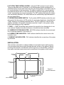
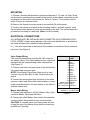
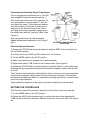
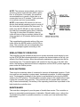
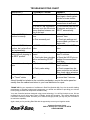
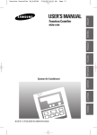
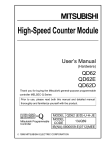
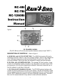
RC-4Bi
RC-7Bi
RC-1260Bi
Instruction
Manual
H
G
F
Figure 1
A
C
B
D
I
E
RC-7BI MODEL SHOWN
(The RC-4Bi has a 20-minute pause position between station #4 and "REST.")
DESCRIPTION OF CONTROLS
Refer to Figure 1
A. HOUR DIAL with 23 CYCLE START PINS: The HOUR dial contains 23 pins for
scheduling automatic "Starts" on any hour (except midnight—which is day changeover
time). Embossed characters provide quick identification for each hour, AM or PM,
noon and midnight. Captive type pins are designed for simple push-pull operation.
B. DAY DIAL with 14 SCHEDULING PINS: The calendar DAY dial contains 14 captive pins for scheduling irrigation everyday or any day within a two week range. Each
pin represents a 24 hour period beginning at midnight. Embossed characters are on
the dial, adjacent to each day of the week.
C. STATION SELECTOR/INDICATOR DIAL: The STATION selector/indicator dial
contains the timing controls (D) for each of the stations. The dial automatically rotates
during a watering cycle with the current station appearing at the top, under the station
pointer. REST indicates the system is off and no watering is taking place. The dial is
also used for manual selection of any station for semi-automatic operation.
1
D. STATION TIME CONTROL KNOBS: Individual TIME controls for each station.
Timing is adjustable up to 60 minutes to suit all landscape growth requirements. A
small white arrow moves with each knob along the timing scale on the Station dial (C)
for visual indication of the time setting. The scale is marked-off in 5 minute graduations and the ratchet action of the knob provides for precision adjustment with each
"notch" representing one minute increments. The OFF position eliminates the station
from the watering schedule. All omitted stations are automatically rapid-advanced to
the next timed station.
E. OPERATIONAL MODE SWITCH: The 2-position MODE switch provides the operating control for the system, AUTO position for automatic irrigation as scheduled and
"timed" watering of a manually selected station. The OFF position is used for rainy
weather shutdown. This position eliminates controller "output" to the system valves
without interrupting the clock operation.
F. FUSE: 1.5 AMP (Slow Blow fuse) protects the controller from damage due to current overload. Replace fuse after the source of trouble has been remedied.
G. CURRENT STATION INDICATOR: STATION indicator identifies the current position of controller operation. See control (C).
H. CURRENT TIME INDICATOR: TIME indicator identifies the current time on the
controller clock.
I. CURRENT DAY INDICATOR: DAY indicator identifies the current day of the watering schedule.
INSTALLATION
The controller is housed in a cabinet suitable for convenient indoor wall mounting.
Four mounting holes are provided through the back surface of the cabinet. Before
mounting the controller, consideration must be given as to accessibility, protection
from water, electrical power source and connections to the system control valves.
11”
7”
MOUNTING
HOLES
1
3 /2”
CONTROLLER
OUTLINE
1
3
3 /4” 7 /4”
Figure 2
CONTROLLER MOUNTING
5
2 /8”
5
1 /8” DIA. VALVE WIRE OUTPUT
CONNECTION
OPENING
DOOR CLEARANCE
3
1 /4”
3
1 /4”
2
MOUNTING
1. Choose a location that provides a minimum clearance of 13" wide x 8" high. Since
the electrical connections are provided at the bottom of the cabinet, clearance should
be allowed for the conduit connections etc. Refer to Figure 2. The location must be
within 5 feet of an electrical outlet.
2. Remove the 4 panel mounting screws, and carefully lift out the panel.
3. Position the cabinet on the wall at the mounting location, and with a pencil, mark
the mounting holes desired (4 holes are provided) on the wall. Two vertical holes are
provided for mounting to a wall stud. (Note: Use #10 screws).
ELECTRICAL CONNECTIONS
ALL WIRING MUST BE INSTALLED AND CONNECTED IN ACCORDANCE WITH
LOCAL CODES. A basic wiring diagram, with color code identification is provided on
the inside surface of the cabinet for easy reference.
1
A /4" dia. hole is provided in the bottom of the cabinet for insertion of the transformer
input wire. See Figure 4.
Valve Output Wiring
The controller transformer provides 24 VAC output for
the station valves. The output leads are color coded and
stamped with the corresponding station designations.
(See Figure 3.)
1. Connect one Lead from each valve to the desired station output lead using wire nuts.
NOTE: If the Master Valve/Pump Start circuit is used,
connect only one Rain Bird, 2 watt, solenoid valve per
station.
2. Connect the second lead from all valves to the white
common output lead. Record the valve locations or landscape zone identification for each station on the label inside the cabinet door.
Master Valve Wiring
1. Connect one lead from a 24 VAC Master Valve to the
controller Master Valve lead (Wht/Orn).
2. Connect the other Master Valve lead to the controller
common (white) along with the valve common leads.
CAUTION: If a master valve is not being used, be sure
to tape the end of the Master Valve lead to prevent any
possibility of "shorting."
3
OUTPUT LEAD
Station 1:
2:
3:
4:
5:
6:
7:
8:
9:
10:
11:
12:
Master Valve:
Valve Common:
(2) Transformer:
COLOR
CODE
Brown
Red
Orange
Yellow
Green
Blue
Violet
Gray
White
White/Blk
White/Bm
White/Red
Wht/Orn
White
Wht/Red
Wht/Red w/ “line input” label
Wht/Brn w/ “line input” label
Figure 3
Instructions for Attaching Plug-In Transformer.
Prior to plugging the transformer into a 120 VAC
1
wall receptacle, insert the wire through the /4"
hole in the lower left corner of the controller, tie
an overhand knot in the wire about 5" from the
end (inside the case). This will prevent inadvertent disconnection of the wire. Connect one orange wire to the wht/red wire with the "line input" label and connect the other orange wire to
the wht/brn wire with the "line input" label. (See
Figure 4)
Now, plug transformer into wall receptacle.
(Note: International transformer is not "plug-in"
type.)
Figure 4
ATTACHING TRANSFORMER TO
CONTRLLER
Electrical System Checkout
1. Rotate the STATION dial counterclockwise to position REST at the top directly under the Station pointer.
2. Pull all pins on the HOUR and DAY dials to the "out" position.
3. Put the MODE switch in the AUTO position.
4. Make sure transformer is plugged into a wall receptacle.
5. Adjust each station TIME control to the 5 minute mark. (See Figure 6.)
6. Rotate the STATION dial (counterclockwise) to position Station 1 under the pointer.
Watering should commence shortly as the automatic mechanism latches with the Station dial.
The 5-minute interval should provide sufficient time to observe control valve operation.
If more time is required, simply adjust the timing knobs as necessary. The controller
will advance through each station, in sequence, providing opportunity to observe each
circuit for proper operation.
Upon satisfactory checkout of the system, proceed to adjust the controller clock.
SETTING THE CONTROLLER
With the main power ON, proceed to adjust the clock for the correct time and day.
1. Put the MODE switch in the OFF position.
2. Rotate the HOUR dial (clockwise only) to position the current time opposite the
TIME pointer at the top of the panel. Observe the dial for the correct AM or PM numerals.
4
Example: If the correct time is 1:35 PM,
position the dial such that the TIME
pointer will point midway between the 1
and 2 numerals on the PM side of the
dial. If a more precise adjustment is desired, the best procedure would be to
push-in the pin corresponding to the upcoming hour (in this example, the 2 PM
pin) and on that hour, slowly rotate the
dial until you hear the "click" of the
micro-switch.
3. Proceed to set the present day by rotating the calendar DAY dial to position
the correct letter opposite the DAY
pointer at the bottom of the dial.
4. Next, rotate the STATION dial in a
counterclockwise direction to position
REST at the top under the STATION
pointer. This completes the controller
clock setting.
SCHEDULING AUTOMATIC OPERATION
Make sure the HOUR and DAY dials are set to the correct time and that all pins are in
the "out" position.
1. Push in the pin(s) corresponding to the day(s) on which watering is desired. Remember, each DAY pin represents a 24 hour period beginning at midnight.
2. Next, select the desired starting time(s) and push in the corresponding pin(s) on the
HOUR dial.
3. The first mark (square dot on the station dial) is the minimum time setting and represents approximately 3 minutes. The small white arrow moves with the knob for visual
indication of each setting. (There will be no valve output when the arrow is positioned
between "off" and the "square dot.'') The ratchet notches represent 1 minute increments for precise settings. The OFF position at each timing dial, omits the station from
the schedule.
5
NOTE: The minimum accumulated cycle time required to prevent a second start within a given
hour is 20 minutes. Conversely, the maximum
accumulated time to permit a cycle start on a
consecutive hour is 55 minutes. Total cycle time
of more than one hour is permissible.
NOTE: It takes about 20 minutes for the hour
dial pin that started a watering cycle to move off
the cycle-start switch behind the face panel. To
make sure the RC-4Bi will not start another cycle when the combined running time of stations
1 through 4 is less than 20 minutes, the controller will stop at the non-existent station #6 position and time out 20 minutes before returning
to "REST."
This completes the automatic setting of the controller. Move the MODE switch to the AUTO position. The controller will now automatically control the landscape irrigation according to the
SEMI-AUTOMATIC OPERATION
The controller may be operated at any time in a semi-automatic mode simply by turning the STATION dial counterclockwise to position the desired station at the top, just
ahead of the Station pointer. Allow the automatic mechanism to advance into the desired timing zone. The selected station will operate for the time set on the dial, after
which, the remaining stations will follow in sequence until the REST position again appears under the Station pointer.
RAIN SHUTDOWN
There may be occasions where it is desired to interrupt all landscape irrigation. Conditions such as rainy weather, system repair, landscape renovation, or other excavation
work. The temporary shutdown of the system is accomplished by moving the MODE
switch to the OFF position. This eliminates controller output to the valves without interrupting the controller timing circuitry. The controller will not operate either automatically or semi-automatically. A summary of the operating instructions is provided on the
label inside the controller door.
MAINTENANCE
The controller is designed to provide years of trouble-free service. The controller requires no preventative maintenance or lubrication. Should trouble occur, refer to the
Troubleshooting chart for possible remedies, or contact your local authorized Rain
Bird dealer.
6
TROUBLESHOOTING CHART
DIFFICULTY
POSSIBLE CAUSE
Clock stopped.
a. Blown fuse
DAY and HOUR dials
function incorrectly.
a. Replace fuse. If controller
stops again, check system
circuits to locate trouble.
b. No power to controller.
b. Check line voltage and
connections at each end.
c. In the RC-4Bi, the station c. Let controller time out for
dial may be in the 20-minute 20-minutes and return to
pause position between sta- "REST" automatically.
tion 4 and rest.
a. Reset clock for the
a. Clock set for incorrect
"present" time.
time.
b. Check pin settings and
b. Pins incorrectly set.
"accumulated cycle time on
station dial.
a. MODE switch in wrong po- a. Move switch to AUTO position.
sition.
DAY and HOUR dials
function, but cycle will not
start automatically.
Controller recycles imme- a. Insufficient cycle time aldiately without stopping in lowed.
the REST position.
b. Total cycle time coincides
with a succeeding START
pin.
Some stations do not op- a. Station time set at OFF.
erate.
b. Faulty valve wiring.
Station dial does not stop
at a "Timed" station
REMEDY
a. Insufficient time set on
dial.
a. Adjust cycle time for more
than 15 minutes.
b. Reset the HOUR pins or
readjust the accumulated
cycle time.
a. Set TIME control for more
than 3 minutes.
b. Check connections between controller and valves.
Also, check valve actuators.
a. Adjust the TIME control
for more than 3 minutes.
Should trouble be isolated in the controller mechanism, remove the entire panel assembly from the cabinet and return to your local distributor for repair.
THANK YOU for your expression of confidence in Rain Bird Sprinkler Mfg. Corp. As the world's leading
manufacturer of irrigation systems and components, our efforts are directed to providing you with the
finest quality products and components available today.
Your new Controller has been designed using proven technology. You will find it simple to use. We are
confident that you will enjoy many years of reliable, trouble-free operation. This manual describes the
Controller's functions in detail. We invite you to read it thoroughly so that you may use your Controller to
its maximum capability.
Again, thank you for providing Rain Bird with the opportunity to meet your irrigation needs.
Customer Support Center
6640 S. Bonney Ave. Tucson, AZ 85706
1-800-RAIN-BIRD
7