Download RFID System - Motionsolutions.com
Transcript
RFID System V680 Series User’s Manual FL Remote ID V680-HAM42-FRT Antenna V680-HS63-SP ID Tag V680-D1KP66T-SP Cat. No. Z268-E1-02 Introduction Thank you for purchasing a V680-series RFID System. This manual describes the functions, performance, and application methods needed for optimum use of the V680-series RFID System. Please observe the following items when using the RFID System. • Allow the RFID System to be installed and operated only by qualified specialist with a sufficient knowledge of electrical systems. • Read and understand this manual before attempting to use the RFID System and use the RFID System correctly. • Keep this manual in a safe and accessible location so that it is available for reference when required. 
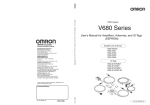
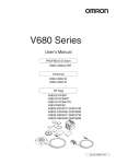
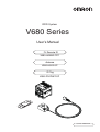
READ AND UNDERSTAND THIS DOCUMENT SECTION 1 Product Overview SECTION 2 Installation, Connections, and Wiring SECTION 3 Preparations for Communications SECTION 4 Functions SECTION 5 Communications SECTION 6 Troubleshooting SECTION 7 Appendices RFID System V680-HAM42-FRT V680-HS63-SP V680-D1KP66T-SP User's Manual FL Remote ID Antenna ID Tag Introduction SECTION 1 SECTION 2 SECTION 3 SECTION 4 SECTION 5 SECTION 6 SECTION 7 Introduction Introduction Introduction READ AND UNDERSTAND THIS DOCUMENT Please read and understand this document before using the products. Please consult your OMRON representative if you have any questions or comments. WARRANTY OMRON’s exclusive warranty is that the products are free from defects in materials and workmanship for a period of one year (or other period if specified) from date of sale by OMRON. OMRON MAKES NO WARRANTY OR REPRESENTATION, EXPRESS OR IMPLIED, REGARDING NON-INFRINGEMENT, MERCHANTABILITY, OR FITNESS FOR PARTICULAR PURPOSE OF THE PRODUCTS. ANY BUYER OR USER ACKNOWLEDGES THAT THE BUYER OR USER ALONE HAS DETERMINED THAT THE PRODUCTS WILL SUITABLY MEET THE REQUIREMENTS OF THEIR INTENDED USE. OMRON DISCLAIMS ALL OTHER WARRANTIES, EXPRESS OR IMPLIED. LIMITATIONS OF LIABILITY OMRON SHALL NOT BE RESPONSIBLE FOR SPECIAL, INDIRECT, OR CONSEQUENTIAL DAMAGES, LOSS OF PROFITS OR COMMERCIAL LOSS IN ANY WAY CONNECTED WITH THE PRODUCTS, WHETHER SUCH CLAIM IS BASED ON CONTRACT, WARRANTY, NEGLIGENCE, OR STRICT LIABILITY. In no event shall responsibility of OMRON for any act exceed the individual price of the product on which liability is asserted. IN NO EVENT SHALL OMRON BE RESPONSIBLE FOR WARRANTY, REPAIR, OR OTHER CLAIMS REGARDING THE PRODUCTS UNLESS OMRON’S ANALYSIS CONFIRMS THAT THE PRODUCTS WERE PROPERLY HANDLED, STORED, INSTALLED, AND MAINTAINED AND NOT SUBJECT TO CONTAMINATION, ABUSE, MISUSE, OR INAPPROPRIATE MODIFICATION OR REPAIR. SUITABILITY FOR USE THE PRODUCTS CONTAINED IN THIS DOCUMENT ARE NOT SAFETY RATED. THEY ARE NOT DESIGNED OR RATED FOR ENSURING SAFETY OF PERSONS, AND SHOULD NOT BE RELIED UPON AS A SAFETY COMPONENT OR PROTECTIVE DEVICE FOR SUCH PURPOSES. Please refer to separate catalogs for OMRON's safety rated products. OMRON shall not be responsible for conformity with any standards, codes, or regulations that apply to the combination of products in the customer’s application or use of the product. At the customer’s request, OMRON will provide applicable third party certification documents identifying ratings and limitations of use that apply to the products. This information by itself is not sufficient for a complete determination of the suitability of the products in combination with the end product, machine, system, or other application or use. The following are some examples of applications for which particular attention must be given. This is not intended to be an exhaustive list of all possible uses of the products, nor is it intended to imply that the uses listed may be suitable for the products: • Outdoor use, uses involving potential chemical contamination or electrical interference, or conditions or uses not described in this document. • Nuclear energy control systems, combustion systems, railroad systems, aviation systems, medical equipment, amusement machines, vehicles, safety equipment, and installations subject to separate industry or government regulations. • Systems, machines, and equipment that could present a risk to life or property. Please know and observe all prohibitions of use applicable to the products. NEVER USE THE PRODUCTS FOR AN APPLICATION INVOLVING SERIOUS RISK TO LIFE OR PROPERTY WITHOUT ENSURING THAT THE SYSTEM AS A WHOLE HAS BEEN DESIGNED TO ADDRESS THE RISKS, AND THAT THE OMRON PRODUCT IS PROPERLY RATED AND INSTALLED FOR THE INTENDED USE WITHIN THE OVERALL EQUIPMENT OR SYSTEM. PERFORMANCE DATA Performance data given in this document is provided as a guide for the user in determining suitability and does not constitute a warranty. It may represent the result of OMRON’s test conditions, and the users must correlate it to actual application requirements. Actual performance is subject to the OMRON Warranty and Limitations of Liability. CHANGE IN SPECIFICATIONS Product specifications and accessories may be changed at any time based on improvements and other reasons. It is our practice to change model numbers when published ratings or features are changed, or when significant construction changes are made. However, some specifications of the product may be changed without any notice. When in doubt, special model numbers may be assigned to fix or establish key specifications for your application on your request. Please consult with your OMRON representative at any time to confirm actual specifications of purchased products. DIMENSIONS AND WEIGHTS Dimensions and weights are nominal and are not to be used for manufacturing purposes, even when tolerances are shown. ERRORS AND OMISSIONS The information in this document has been carefully checked and is believed to be accurate; however, no responsibility is assumed for clerical, typographical, or proofreading errors, or omissions. PROGRAMMABLE PRODUCTS OMRON shall not be responsible for the user’s programming of a programmable product, or any consequence thereof. COPYRIGHT AND COPY PERMISSION This document shall not be copied for sales or promotions without permission. This document is protected by copyright and is intended solely for use in conjunction with the product. Please notify us before copying or reproducing this document in any manner, for any other purpose. If copying or transmitting this document to another, please copy or transmit it in its entirety. 2 RFID System User's Manual Introduction Introduction Safety Precautions ● Alert Symbols for Safe Use The following symbols are used in this manual to indicate precautions that must be observed to ensure safe use of the V680-HAM42-FRT/V680-HS63-SP/V680-D1KP66T-SP. The precautions provided here contain important safety information. Be sure to observe these precautions. The following signal words are used in this manual. Indicates a potentially hazardous situation which, if not avoided, will result in minor or WARNING moderate injury, or may result in serious injury or death. Additionally, there may be significant property damage. ● Meanings of Alert Symbols Indicates general prohibitions for which there is no specific symbol. ● Warning WARNING This Product is not designed to be used either directly or indirectly in applications that detect human presence for the purpose of maintaining safety. Do not use this Product as a sensing device for protecting human lives. RFID System User's Manual 3 Introduction Introduction Regulations and Standards The V680-HAM42-FRT conforms to the following overseas regulations and standards. 1. U.S.A., Canada U.S.A.: FCC Rules (Federal Communications Commission) Canada: IC Rules (Industry Canada) FCC Part15 subpart C, RSS-Gen FCC ID: E4E6CYSIDV6800507 IC: 850J-V6800507 This device complies with part 15 of the FCC Rules and RSS-Gen of IC Rules. Operation is subject to the following two conditions: (1)This device may not cause harmful interference. (2)This device must accept any interference received, including interference that may cause undesired operation. FCC Part15 subpart B NOTICE This equipment has been tested and found to comply with the limits for a Class A digital device, pursuant to part 15 of the FCC Rules. These limits are designed to provide reasonable protection against harmful interference when the equipment is operated in a commercial environment. This equipment generates, uses and can radiate radio frequency energy and, if not installed and used in accordance with the instructions, may cause harmful interference to radio communications. Operation of this equipment in a residential area is likely to cause harmful interference in which case the user will be required to correct the interference at his own expense. ICES-003 This class A digital apparatus complies with Canadian ICES-003. WARNING Changes or modifications not expressly approved by the party responsible for compliance could void the user's authority to operate the equipment. Do not remove the ferrite core (TDK Type ZCAT1525-0430AP) installed on the cables to suppress RF interference. And attach the accompanying ferrite core (TDK Type ZCAT2032-0930) around the cables that are connected with the power and grounding terminals. UL508 Use the V680-HAM42-FRT connected to the following circuit 1 or 2. Circuit 1: A circuit with a restricted voltage and current as certified by UL508. Use a circuit that uses the windings of the secondary side of an insulating transformer that satisfies the following two conditions as the power supply: • Maximum voltage with no load: 30 Vrms, 42.4 V peak 4 RFID System User's Manual Introduction b) A current restricted by a fuse or other circuit protector with the ratings in the following Introduction • Maximum current: a) 8 A (including short-circuit current) or table: No-load voltage (V peak) 0 to 20 More than 20 to 30 Maximum rated current (A) 5.0 100 Peak voltage Circuit 2: A Class 2 circuit, i.e., a circuit with a maximum voltage of 30 Vrms (42.4 V peak) that uses a Class 2 power supply unit compliant with UL1310 or a Class 2 transformer compliant with UL1585 as the power supply. RFID System User's Manual 5 Introduction Introduction 2. Europe EC-R&TTE (Radio and Telecommunications Terminal Equipment Directive 1999/5/EC) Radio: EN 300 330 EMC: EN 301 489 Safety: EN 61010-1 English Hereby, Omron, declares that the RFID System, V680-HS63-SP Series, and V680-HAM42-FRT Series are in compliance with the essential requirements and other relevant provisions of Directive 1999/5/EC. Finnish Omron vakuuttaa täten että RFID Säännös, V680-HS63-SP Series, V680-HAM42-FRT Series tyyppinen laite on direktiivin 1999/5/EY oleellisten vaatimusten ja sitä koskevien direktiivin muiden ehtojen mukainen. Dutch Hierbij verklaart Omron dat het toestel de RFID Systeem, V680-HS63-SP ´Serie, V680-HAM42-FRT ´Serie in overeenstemming is met de essentiële eisen en de andere relevante bepalingen van richtlijh 1999/5/EG. French Par la présente Omron déclare que la RFID Système, V680-HS63-SP Série, V680-HAM42-FRT Série sont conforme aux exigences essentielles et aux autres dispositions pertinentes de la directive 1999/5/CE. Swedish Härmed intygar Omron att den RFID System, V680-HS63-SP Serie, V680-HAM42-FRT Serie stär l överensstämmelse med de väsentliga egenskapskrav och övriga relevanta bestämmelser som framgår av direktiv 1999/5/EG. Danish Undertegnede Omron erklærer herved, at følgende den RFID System, V680-HS63-SP Serie, 680-HAM42-FRT Serie overholder de væsentlige krav og øvrige relevante krav i direktiv 1999/5/EF. German Hiermit erklärt Omron, die RFID System, V680-HS63-SP Serie, V680-HAM42-FRT Serie in Übereinstimmung mit den grundlegenden Anforderungen und den anderen relevanten Vorschriften der Richtlinie 1999/5/EG befindet. (BMWi) Greek ME THN ΠAPOYSA Omron ∆HΛONEI RFID O’YO’ΓΗΜΑ, V680-HS63-SP O’EIPA, V680-HAM42-FRT O’EIPA SYMMOPF ONETAI ΠPOS TIS OYSIO∆EIS AΠAITHSEIS KAI TIS ΛOIΠES SXETIKES ∆IATAΞEIS THS O∆HΓIAS 1999/5/EK. Italian Con la presente Omron dichiara che la RFID Sistema, V680-HS63-SP Serie, V680-HAM42-FRT Serie sono conforme ai requisiti essenziali ed alle altre disposizioni pertinenti stabilite dalla direttiva 1999/5/CE. Spanish Por medio de la presente Omron declara que el RFID Sistema, V680-HS63-SP Serie, V680-HAM42-FRT Serie esta conforme a los requisitos esenciales y cualesquiera otras disposiciones aplicables o exigibles de la Directiva 1999/5/CE. Portuguese Omron declara que a RFID Sistema, V680-HS63-SP Série, V680-HAM42-FRT Série ser conforme com os tequisitos essenciais e outras disposições da Directiva 1999/5/CE. Romanian Prin prezenta, Omron declar c acest V680-HS63-SP, V680-HAM42-FRT este conform cu cerin ele principale çi cu celelalte prevederi relevanate ale Directivei 1999/5/EC. Note the following points in using the RFID System: • Do not remove the ferrite core (TDK Type ZCAT1525-0430AP) from the Antenna Cable because it is necessary for suppressing signal interference. Also, be sure to attach the ferrite core (TDK Type ZCAT2032-0930) that comes as an accessory with the V680-HAM42-FRT to the cable that is connected to the power supply terminal and ground terminal. 3. Japan Radio Law Equipment using high frequencies: Inductive Reading/Writing Communications Equipment Conforming standards: Inductive Reading/Writing Communications Equipment; Standard: ARIB STD-T82; Specification number: EC-07022 6 RFID System User's Manual Introduction Introduction 4. China Antenna CMII ID: 2008DJ0145 V680-HS63-SP RFID System User's Manual 7 Introduction Introduction Precautions for Safe Use Be sure to observe the following precautions to ensure safe use of the Products. 1. Do not use the Products in environments with flammable, explosive, or corrosive gasses. 2. Do not attempt to disassemble, repair, or modify any Product. 3. Tighten mounting screws securely. 4. Be sure to use crimp terminals of the specified size for wiring. 5. If any cable has a locking mechanism, make sure that it has been locked before using the cable. 6. Make sure the power supplied by the DC power supply unit is within the rated power supply voltage (24 VDC +10%/−15%) before using the Product. 7. Do not connect the power supply in reverse. 8. Do not allow water or pieces of wire to enter from openings in the case. Doing so may cause fire or electric shock. 9. Turn OFF the FL Remote ID power before attaching or removing the Read/Write Antenna. 10. If an error is detected in any Product, immediately stop operation and turn OFF the power supply. Consult with an OMRON representative. 11. Dispose of the Products as industrial waste. 12. Do not touch the product immediately after usage at high temperatures. Doing so may occasionally result in burning. 13. If multiple Antennas are mounted near each other, communications performance may decrease due to mutual interference. Refer to Mutual Interference between Antennas (Reference) and check to make sure there is no mutual interference. 14. Provide sufficient ventilation space. 15. Do not install the Products near any equipment that generates a large amount of heat (such as heaters, transformers, and large-capacity resistors). 16. Do not clean the Products with paint thinner, benzene, acetone, or kerosene. 17. Observe all warnings and precautions given in the body of this manual. 8 RFID System User's Manual Introduction Always observe the following precautions to prevent operation failures, malfunctions, and adverse effects on Introduction Precautions for Correct Use performance and equipment. 1. Installation Environment Do not use the Products in the following locations. • Locations exposed to corrosive gases, dust, metallic powder, or salts • Locations not within the specified operating temperature range • Locations subject to rapid changes in temperature or condensation • Locations not within the specified humidity range • Locations subject to direct vibration or shock outside the specified ranges • Locations subject to spray of water, oil, or chemicals 2. Installation • The Products communicate with Tags using the 13.56-MHz frequency band. Some motors, inverters, and switching power supplies generate noise that can affect communications with the Tags and cause errors. If such devices are located near the Tags, always test operation in advance to confirm whether the system will be affected. • Observe the following precautions to minimize the effects of normal noise. (1)Ground all metal objects in the vicinity of the Products to 100 Ω or less. (2)Do not use the Products near high-voltage or high-current lines. • When mounting the Products, tighten the screws to the following torques. V680-HS63-SP: 1.2 N·m V680-D1KP66T-SP: 1.2 N·m 3. Storage Do not store the Products in the following locations. • Locations exposed to corrosive gases, dust, metallic powder, or salts • Locations not within the specified storage temperature range • Locations subject to rapid changes in temperature or condensation • Locations not within the specified storage humidity range • Locations subject to direct vibration or shock outside the specified ranges • Locations subject to spray of water, oil, or chemicals RFID System User's Manual 9 Introduction Introduction Meanings of Symbols 10 Meanings of Symbols Indicates particularly important points related to a function, including precautions and application advice. Indicates page numbers containing relevant information. Indicates reference to helpful information and explanations for difficult terminology. RFID System User's Manual Introduction Introduction TABLE OF CONTENTS Introduction READ AND UNDERSTAND THIS DOCUMENT 2 Safety Precautions 3 Regulations and Standards 4 Precautions for Safe Use 8 Precautions for Correct Use 9 Meanings of Symbols 10 TABLE OF CONTENTS 11 SECTION 1 Product Overview 13 Features 14 Part Names and Functions 16 System Configuration 21 Application Flowchart 22 SECTION 2 Installation, Connections, and Wiring 23 FL Remote ID 24 Installing Antennas 29 Installing ID Tags 31 SECTION 3 Preparations for Communications Parameter Settings for FL Remote Communications SECTION 4 Functions 33 34 37 Communications Specifications 38 Write Protection 41 Noise Measurement 44 ID Tag Service Life Warning Management 45 RFID System User's Manual 11 Introduction Introduction SECTION 5 Communications 51 I/O Specifications 52 Detailed Command Settings 55 Timing Charts 59 SECTION 6 Troubleshooting 63 Handling Errors 64 Errors and Countermeasures 66 Maintenance and Inspection 67 SECTION 7 Appendices Specifications and Dimensions 70 Characteristics According to Operating Conditions 76 Tag Memory Map 78 Tag Memory Capacity and Memory Type 79 Degree of Protection 80 Revision History 12 69 RFID System User's Manual 82 SECTION 1 SECTION 1 Product Overview 14 Part Names and Functions 16 System Configuration 21 Application Flowchart 22 RFID System User's Manual Product Overview Features 13 SECTION 1 Product Overview Features The V680-series RFID System uses electromagnetic induction and supports the ISO/IEC18000-3 (ISO/ SECTION 1 IEC15693) RFID system international standards. Features ■ Highly Reliable Tag Communications The V680 features highly reliable ID Tag communications developed through the V600-series RFID Systems, making it easy to use on-site. ■ Compatible with FL Remote The FL Remote ID is compatible with the FL Remote system, a remote I/O system based on FL-net (OPCN-2). It can be easily installed using LAN cables and easily programmed through I/O controls. ■ Compact Design with an Internal Amplifier With a compact size of 65 × 65 × 65 (W × H × D) mm, the FL Remote ID requires less space for installation. ■ Antennas and Tags with Superior Environmental Resistance Fluororesin has superior environmental resistance, and is used for the external coatings of the Antenna case, Antenna cable, and the ID Tags. ■ EEPROM Memory Capacity of 1,000 Bytes The ID Tags have 1,000 bytes of EEPROM memory capacity. They can be used to store various data, which can be rewritten up to 100,000 times per block if used at an ambient temperature not exceeding 25°C. 14 RFID System User's Manual SECTION 1 Product Overview ■ ID Tag Service Life Warning Management The EEPROM has a service life of 100,000 data write operations. With the FL Remote ID, the service operations to each block of the ID Tag is counted and saved to a special area of each ID Tag. Warning is output if the number of data write operations exceeds 100,000. RFID System User's Manual Features Note: A memory capacity of 992 bytes is required to enable ID Tag service life warning management. SECTION 1 life for data write operations of ID Tags can be managed automatically. The total number of data write 15 SECTION 1 Product Overview Part Names and Functions Part Names SECTION 1 Part Names and Functions ■ Operation Indicators DEV: Unit status (green/red) RMT: FL Remote network status (green/red) T/R: ID Tag communications status (yellow) NORMAL/ERROR: FL Remote ID operation result (green/red) ■ Data Display Data display (green) Error code display (red) ■ Mode Switch FL Remote ID operation mode setting switch ■ Node Address Switch Node Address Switches (01 to 64) ■ FL Remote Connector Connects to FL Remote Master Unit ■ Power Supply Terminals Connect to 24-VDC power. Recommended Power Supply: S8VS-03024 (OMRON) ■ Antenna Connector Connects to V680-HS63-SP Antenna 16 RFID System User's Manual SECTION 1 Product Overview ■ Operation Indicators DEV (Device Status) The DEV indicator displays the Unit status. Lit green Flashing red Not lit Definition Normal Fatal error Part Names and Functions Lit red SECTION 1 Status Non-fatal error No power RMT (Remote Status) The RMT indicator displays the FL Remote network status. Status Lit green Flashing green Definition Adding link/Participating in remote communications Adding link/Leaving remote communications Flashing green and red Adding link/Remote classification error or setting error Lit red Duplicate node address or duplicate common address Flashing red Not lit Withdrawn from link Not linked. T/R The TR indicator displays the Tag communications status. Status Lit yellow Not lit Definition Tag is communicating Standby NORMAL/ERROR Status Lit green Definition Normal end Lit red Error end Not lit Standby ■ Data Display and Error Code Display The Data Display shows the first byte of data that was read or written when communications ends normally. It displays the error code if communications ends in an error. Status Lit green Lit red Flashing red Not lit Definition Data displayed. System error displayed. Error code displayed. Display turned OFF. For details, refer to the RFID-related Errors. p.64 RFID System User's Manual 17 SECTION 1 Product Overview ■ FL Remote Connector Port This connector connects the FL Remote to the Master Unit. SECTION 1 8 Part Names and Functions 1 Pin No. Name Description I/O 1 TX_D1+ Transmitted data + Output 2 TX_D1− Transmitted data − Output 3 RX_D2+ Received data + Input 4 --- 5 --- 6 RX_D2− 7 --- 8 --- Hood GR ----Received data − Input ----- Internal functional ground --- ■ Power Supply Terminals The power supply terminals supply 24-VDC power using the included connector. Included connector model: FKC2.5/3-ST-5.08-RF (Phoenix Contact) 1 2 3 Pin No. Name Description 1 24V 24V --- 2 GND GND --- 3 GR Functional ground (Ground to 100 Ω or less.) --- Use the recommended OMRON Power Supply, the S8VS-03024. 18 I/O RFID System User's Manual SECTION 1 Product Overview ■ Antenna Connector Port Connects the V680-HS63-SP Antenna. 1 SECTION 1 Pin No. Name Description I/O 1 S Signal line --- 2 GND Analog ground --- ■ Node Address Switches Part Names and Functions 2 The node address switches set the FL Remote Node Address. This node address is used as the rightmost part of the IP address (e.g., xx of 192.168.250.xx). RMT NORM/ERR 4 NODE No. 78 78 4 56 4 56 OMRON Corporation 1 X10 0 FSM 23 X10 1 SOURCE : 24VDC 0.3A 3 2 MODE 901 23 23 78 901 4 56 901 OFF RFID MADE IN JAP NODE No. 78 X10 1 23 23 78 901 456 901 X10 0 456 Item Description Setting method Two-digit decimal number The left rotary switch sets the 10s digit, and the right rotary switch set the 1s digit. Setting range 01 to 64 The default setting is 01. An address error will occur if "00" or "65" to "99" are set. Turn the power OFF before setting the node address switches. The node address that is set when the power is turned ON will be valid. RFID System User's Manual 19 SECTION 1 Product Overview ■ Mode Switch The mode switch sets the FL Remote ID operation mode. RMT NORM/ERR 3 78 X10 0 FSM 4 56 4 56 MRON Corporation 4 56 78 0 23 X10 1 OURCE : 24VDC 0.3A 2 1 MODE 901 23 78 901 23 SECTION 1 NODE No. 901 OFF RFID MADE IN JAPAN MODE 78 23 456 Part Names and Functions 901 F No. Item Description 0 Trigger The input signal triggers communications and outputs the result. 1 Auto mode Communications are repeatedly executed and the results are output. 2 Test mode Operation can be checked while disconnected from the Master Unit by reading 4 bytes from address 00. 3 Noise level measurement mode The noise conditions around the Antenna can be measured without connecting to the Master Unit. Other - (A mode setting error will occur if any other settings are made.) Turn the power OFF before setting the mode switch. The mode that is set when the power is turned ON will be valid. 20 RFID System User's Manual SECTION 1 Product Overview System Configuration The system configuration is shown in the following figure. SECTION 1 FL Remote Master Unit System Configuration 20 Units max. Hub Hub Hub Cable length: 100 m max. Cable length: 100 m max. 5 DEV 1 RMT X10 OMRON Corporation 78 78 78 4 56 SOURCE : 24VDC 0.3A 4 56 78 RMT X10 FSM V680-HAM42-FRT TR 8 7 6 5 NORM/ERR 4 3 2 MODE 1 NODE No. 90 1 4 56 4 56 4 56 78 DEV 1 OFF RFID 90 1 X10 1 SOURCE : 24VDC 0.3A OMRON Corporation MADE IN JAPAN 90 1 X10 0 FSM 23 78 5 23 MADE IN JAPAN 6 90 1 0 23 RFID 7 3 2 MODE 23 OFF 8 4 23 FSM 1 OMRON TR NORM/ERR 90 1 23 X10 4 56 OMRON Corporation 23 23 23 X10 SOURCE : 24VDC 0.3A V680-HAM42-FRT NODE No. 90 1 78 6 90 1 78 7 3 2 MODE 0 78 8 4 90 1 1 OMRON TR NORM/ERR NODE No. 90 1 4 56 DEV RMT 4 56 V680-HAM42-FRT OMRON 4 56 V680-HAM42-FRT FL Remote ID 64 Units max. OFF RFID MADE IN JAPAN V680-HS63-SP Antennas V680-D1KP66T-SP ID Tags ■ Configuration Description Name Description FL Remote Master Use a JTEKT PLC that is compatible with the FL Remote for the FL Remote Master. Also use a programming tool that is compatible with the FL Remote Master. Contact JTEKT for product details. Hub Use the JTEKT FE-SWH05/08. Cable Use the communications cable for FL Remote (category 5 or higher, with shield). Use straight cables between Hubs and FL Remote IDs. Use a cross cable when connecting the FL Remote Master and FL Remote ID directly. FL Remote ID Up to 64 FL Remote ID Units can be connected. The V680-HS63-SP Antenna can be connected to communicate with V680-D1KP66T-SP ID Tags. Before use, check the restrictions on FL Remote Master Unit. RFID System User's Manual 21 SECTION 1 Product Overview Application Flowchart SECTION 1 Install the system. Preparations Application Flowchart Connect the system. Preparations for Communications p.26 Communications 22 p.24 RFID System User's Manual Set the FL Remote ID communications conditions. p.34 Perform actual communications using commands. p.55 SECTION 2 Installation, Connections, and Wiring SECTION 2 24 Installing Antennas 29 Installing ID Tags 31 RFID System User's Manual Installation, Connections, and Wiring FL Remote ID 23 SECTION 2 Installation, Connections, and Wiring FL Remote ID Installation To ensure full functionality of the V680-HAM42-FRT FL Remote ID, follow the instructions provided in this section for installation. SECTION 2 ■ Installation Site Do not install the ID Controller in the following locations. • Locations exposed to ambient temperatures that are not between −10 and 55°C or where there are FL Remote ID radical temperature changes resulting in condensation • Locations exposed to humidity that is not between 25% and 85% • Locations subject to corrosive gas, flammable gas, dust, salt, or metal powder • Locations that will expose the ID Controller to direct vibration or shock • Locations exposed to direct sunlight • Locations exposed to spray of water, oil, or chemicals • Locations more than 2,000 m above sea level ■ Mounting in a Panel The FL Remote ID Unit can be used at an ambient temperature range of −10 to 55°C. Be sure to observe the following precautions. • Make sure that the Unit is provided with sufficient ventilation space. • Do not install the Unit close to heaters, transformers, or large-capacity resistors that radiate excessive heat. ■ Installation Method DIN Track V680-HAM42-FRT OMRON DEV RMT TR 8 7 6 5 NORM/ERR 4 3 2 MODE 1 NODE No. 78 78 4 56 4 56 SOURCE : 24VDC 0.3A X10 0 FSM 23 23 X10 1 90 1 23 78 90 1 4 56 90 1 OFF RFID OMRON Corporation MADE IN JAPAN End Plate End Plate 65 Mounting Hook A OMRON PFP-100N (track length: 1 m) is recommended. DIN Track PFP-100N End Plate PFP-M B 1. First hook the FL Remote ID Unit to part A, then press it in direction B to mount it to the DIN Track. 2. To disconnect the FL Remote ID Unit from the DIN Track, pull the mounting hook downwards, and then lift the Unit upwards. 24 RFID System User's Manual SECTION 2 Installation, Connections, and Wiring Attaching the End Plates To mount an End Plate easily, first hook the bottom of the End Plate and then hook the top on the DIN Track, pull the End Plate downwards and tighten the screw. Recommended tightening torque: 1.2 N·m. SECTION 2 The V680-HAM42-FRT FL Remote ID Units will generate heat if they are mounted side-by-side. Leave space between Units of at least 10 mm. 10 mm min. DEV 1 RMT RMT 78 78 78 4 56 OMRON Corporation 4 56 78 DEV 1 X10 0 FSM 4 56 4 56 78 5 OFF RFID Spacer 8 7 6 5 4 3 2 MODE 1 90 1 X10 1 SOURCE : 24VDC 0.3A MADE IN JAPAN TR NORM/ERR NODE No. 90 1 OMRON Corporation 90 1 X10 0 FSM 23 4 56 78 6 90 1 23 Spacer 7 3 2 MODE 23 X10 1 SOURCE : 24VDC 0.3A MADE IN JAPAN 8 4 23 RFID 23 4 56 End Plate FSM OFF V680-HAM42-FRT OMRON TR NORM/ERR 90 1 23 OMRON Corporation X10 0 23 23 SOURCE : 24VDC 0.3A 23 X10 1 V680-HAM42-FRT NODE No. 90 1 78 5 78 6 90 1 78 7 3 2 MODE 90 1 4 56 8 4 NODE No. 90 1 OMRON TR NORM/ERR DEV RMT 4 56 V680-HAM42-FRT OMRON 4 56 10 mm min. FL Remote ID ■ Mounting Interval OFF RFID MADE IN JAPAN End Plate Use at least 2 OMRON DIN Track Spacers. (Each Spacer is 5 mm wide.) Spacer PFP-S RFID System User's Manual 25 SECTION 2 Installation, Connections, and Wiring Connection and Wiring ■ FL Remote Connector Installation Hold the connector part of the cable and insert it into the FL Remote Port. SECTION 2 FL Remote ID Removal Unlock the connector and pull it out. ■ Antenna Connector Mounting the Antenna 1. Hold the connector part of the Antenna and insert it into the Antenna port while matching the key on the Unit with the groove on the connector. Key Antenna connector 2. Turn the connector clockwise to lock it in place. 26 RFID System User's Manual SECTION 2 Installation, Connections, and Wiring Removing the Antenna 1. Turn the connector in counterclockwise to release the lock. SECTION 2 FL Remote ID 2. Pull the connector straight out of the port. The connector cannot be removed without turning it to release the lock. If the cable is pulled without releasing the lock, it may cause the cable or wires to break. Make sure that the lock is released before pulling out the Antenna connector connector. RFID System User's Manual 27 SECTION 2 Installation, Connections, and Wiring ■ Power Supply Connector Use the connector that comes with the Unit. You must provide the connecting cable. Brand Cable Power line --- Connector SECTION 2 Crimp Terminal FL Remote ID Crimping Tool Model --- Note 1.0 mm2 (equivalent to AWG18) FKC2.5/3-ST-5.08-RF When one line is connected to one terminal When two lines are connected to one terminal AI1-10RD Phoenix Contact AI-TWIN2×1-10RD CRIMPFOX UD6 --------- 1. Attach the crimp terminals to the sections of the cable where the sheath has been stripped. 2. Make sure the connector is facing the right direction and insert each crimp terminal into the correct connector hole. 3. Once all of the cables have been connected to the connector, attach the connector to the FL Remote ID Unit. Align the cable connector with the connector on the FL Remote ID Unit. Hold the connector body and push the connector firmly into place. Removing the Connector Remove the connector by pressing in on the lock on the cable connector to release the lock and pulling the connector straight out. If the connector is difficult to remove, press on the FL Remote ID Unit while pulling on the connector. Do not connect cables to the connector after attaching the connector to the FL Remote ID Unit. Use the recommended Power Supply (S8VS-03024, OMRON). 28 RFID System User's Manual SECTION 2 Installation, Connections, and Wiring Installing Antennas Installation from the Front Secure the Unit with M4 screws and washers. Coil center Two, M4 holes SECTION 2 28 ±0.2 40 Installing Antennas 27 53 Installation from the Back Secure the Unit with M4 screws and washers. Coil center Two, 4.5 dia. holes Nut 28 ±0.2 27 Securely tighten screws to a maximum torque of 1.2 N·m. RFID System User's Manual 29 SECTION 2 Installation, Connections, and Wiring Effect of Surrounding Metals on the Antenna (Reference) Instead of mounting the Antenna on the surface, it can be embedded into the metal work to prevent collision with the workpiece and/or equipment. If the Antenna is too close to metal, the communications capabilities may be significantly affected. Make sure that the following minimum distances are maintained when mounting the Antenna this way. 23 mm max. SECTION 2 R12 min. 30 mm min. Installing Antennas 60 mm min. Metal casing Metal casing 30 mm min. 30 mm min. 30 mm min. Do not bend the cable into a curve tighter than 12 mm in radius. The communications distance will be reduced significantly if the Antenna is installed closer than 30 mm to metal surfaces. Mutual Interference between Antennas (Reference) To prevent malfunctioning due to mutual interference when using more than one Antenna, leave sufficient space between them as shown in the following diagrams. ■ V680-HS63-SP Installing the Antennas Facing Each Other 420 mm min. 30 RFID System User's Manual Installing the Antennas in Parallel 260 mm min. SECTION 2 Installation, Connections, and Wiring Installing ID Tags Mounting the ID Tags Mount the ID Tags with M5 screws and washers. Tightening torque: 1.2 N·m. There are no restrictions to the mounting direction of the ID Tags or the direction of movement for SECTION 2 Antennas. Installing ID Tags Mounting hole dimensions Two, M5 80 ±0.2 Effect of Metal behind Tags (Reference) Mounting ID Tags to metal workpieces or palettes will affect the communications capabilities. Place non-metallic parts (e.g., plastic or resin) between the metallic parts by referring to the following relationship between the distance between the ID Tag and the metallic body versus the communications distance. (%) 100 Tag Antenna 80 70 60 50 40 30 20 Metal on back 90 Non-Metallic material The communications distance without metal is 100%. V680-HS63-SP & V680-D1KP66T-SP Y Communications distance X 10 0 10 20 30 40 50 (mm) Distance to metal (x) RFID System User's Manual 31 SECTION 2 Installation, Connections, and Wiring Influence of Tag Angle (Reference) Communications are possible even when an Antenna and a Tag are mounted at an angle, but the communications distance will be shortened. The relation between the angle and the communications Installing ID Tags Reduction in maximum communications distance SECTION 2 V680-HS63-SP & V680-D1KP66T-SP (%) 100 90 80 Non-Metallic material distance is shown below. θ 70 60 50 Tag 40 30 20 10 Antenna 0 0 10 20 30 40 50 60 70 80 (θ°) Tag angle Mutual Interference with Tags (Reference) To prevent malfunctioning due to mutual interference when using more than one Tag, leave sufficient space between them as shown in the following diagram. 100 mm 100 mm 32 RFID System User's Manual 100 mm 100 mm SECTION 3 Preparations for Communications 34 SECTION 3 Parameter Settings for FL Remote Communications Preparations for Communications RFID System User's Manual 33 SECTION 3 Preparations for Communications Parameter Settings for FL Remote Communications Set the following link parameters of the JTEKT PLC to enable using the FL Remote ID. Refer to the JTEKT Master Operation Manual for details on how to set the Link No., Slot No., and Link Module Name. Use JTEKT PCwin Ver 8.** Programming Tool to set the parameters of the FL Remote ID. SECTION 3 Communications Transmission Bytes The number of communications transmission bytes for the FL Remote ID is shown in the following table. Parameter Settings for FL Remote Communications No. of input bytes No. of output bytes 8 8 Example Settings This section describes the parameters that can be set with PCwin. ■ Example of System Configuration FL Remote Master Unit Hub ■ I/O Module Settings Select I/O Module from the PCwin Parameter Menu and select the rack number and slot number where the Module is installed. Click the Settings Button in the I/O Module Dialog Box and select the following settings for the I/O Module. • Module Type: (R) Special/Communications • Module Name: FL Remote M ■ Link Parameter Settings Select Link Parameter from the parameter menu and select the program number and link number. Click Link Settings in the Link Parameter Settings Dialog Box. Select the following Link Module name. • Link Module Name: FL Remote M 34 RFID System User's Manual SECTION 3 Preparations for Communications ■ FL Remote M Detail Settings Click the Details Button in the Link Parameter Settings Dialog Box and select the parameter that you want to use. The FL Remote ID does not have a diagnostic function. Parameters cannot be set for this function. ■ Slave Settings Communications Procedure Click the Slave Settings (E) Button in the FL Remote M Detail Settings Dialog Box and set the • Slave Connection Settings Select • Transfer bytes Settings 8 input bytes, 8 output bytes • Expansion Settings Disable SECTION 3 parameters as shown below. Parameter Settings for FL Remote Communications RFID System User's Manual 35 SECTION 3 Preparations for Communications MEMO SECTION 3 Parameter Settings for FL Remote Communications 36 RFID System User's Manual SECTION 4 Functions 38 Write Protection 41 Noise Measurement 44 ID Tag Service Life Warning Management 45 SECTION 4 Communications Specifications Functions RFID System User's Manual 37 SECTION 4 Functions Communications Specifications With the FL Remote ID, communications with the ID Tags is determined by the operating mode set on the mode switch, the command selected, and the options selected to execute the command. Operating mode There are four operating modes. For the mode settings, refer to Part Names and Functions in Section 1. p.16 SECTION 4 ■ Trigger Mode When the ID Tag on a workpiece or palette moves within the communications range of the Antenna, it is detected by a sensor or a switch. A control signal (trigger signal) is output from the PLC to the FL Communications Specifications Remote ID, which triggers the FL Remote ID to begin communications with the ID Tag. The FL Remote ID reads the Tag data and outputs the results to the PLC. FL Remote Master Unit ID Tag V680-D1KP66T-SP FL Remote ID V680-HAM42-FRT Antenna V680-HS63-SP Palette, etc. Sensor or Switch ■ Auto Mode When the ID Tag of a workpiece or palette is within the communications range of the Antenna, the Remote ID automatically begins communications with the ID Tag and outputs the result to the PLC. FL Remote Master Unit FL Remote ID V680-HAM42-FRT Antenna V680-HS63-SP ID Tag V680-D1KP66T-SP 38 RFID System User's Manual Palette, etc. SECTION 4 Functions ■ Test Mode During system installation or maintenance, set the switch on the Unit to Test Mode. When the power supply is turned ON, the ID Tag data will be read, and the communications results will be displayed on the indicators. ■ Noise Level Measurement Mode If communications with the ID Tag is unstable, set the switch on the Unit to the Noise Level Measurement Mode. When the power supply is turned ON, the noise around the Antenna will be measured, and the noise measurement results will be displayed on the indicators. Commands Communications with the ID Tag is controlled by commands allocated to the FL Remote signals. SECTION 4 • READ • WRITE • DATA FILL • NOISE MEASUREMENT Refer to Noise Measurement for details. p.44 ■ READ Data in the ID Tag memory is read by specifying the number of bytes to process. ■ WRITE Data is written to the ID Tag by specifying the memory address, number of bytes to process, and the Communications Specifications Noise measurement is not a command used for communications with ID Tag, but a command used for maintenance. data. ■ DATA FILL Based on the specified address, number of blocks to process, and data, the specified memory area of the ID Tag is filled with the same data. ■ NOISE MEASUREMENT The strength of noise received by the Antenna is measured. RFID System User's Manual 39 SECTION 4 Functions Options The following functions can be used by setting the control signal options settings. • Communications Speed • Write Protection • Output Time • ID Tag Service Life Warning Management ■ Communications Speed The communications time required for writing large amounts of data to the ID Tag using the DATA FILL command can be reduced by setting the communications speed to high. Be aware that the noise resistance may be lower during communications when this function is being used. SECTION 4 For details on the communications time, refer to Communications Time (Reference). p.77 Communications Specifications ■ Write Protection Important data stored in the memory of an ID Tag, such as the product model or type, can be protected from being overwritten inadvertently by enabling the Write Protection function. Refer to Write Protection for details. p.41 ■ Output Time When auto mode is being used, the result output time can be set to either 100 ms or 500 ms. Refer to Timing Charts for details on output timing. p.59 ■ ID Tag Service Life Warning Management With the FL Remote ID, the service life for data write operations can be automatically managed, and a warning can be output if the number of data write operations exceeds 100,000. A memory capacity of 992 bytes is required to enable ID Tag service life warning management. Refer to ID Tag Service Life Warning Management for details. p.45 40 RFID System User's Manual SECTION 4 Functions Write Protection The write protection function protects important data stored in the memory of a Tag, such as the product model or type, from being overwritten inadvertently. Enable the write protection function after writing important data as described in this section. Setting Write Protection For the write protection function to be effective, it must be enabled or disabled in both the FL Remote ID settings and the ID Tag settings. 1. FL Remote ID Settings The write protection function can be enabled or disabled by setting the write-protect bit of the FL SECTION 4 Remote ID in the I/O Allocation Table. Refer to the I/O Allocation Table and Signal Names and Functions for details. Write Protection p.52, p.53 2. ID Tag Settings Write protection for individual ID Tags is set in the most significant bit of address 0000 hex. Write protection is set in the 4 bytes from Tag address 0000 to 0003 hex. Address 0000 hex Bit 7 6 Enable/disable 5 4 3 2 1 0 Upper two digits of start address (00 to 7F) 0001 hex Lower two digits of start address (00 to FF) 0002 hex Upper two digits of end address (00 to FF) 0003 hex Lower two digits of end address (00 to FF) • Write-protect bit (most significant bit of address 0000 hex) 1: Write-protected (Enable) 0: Not write-protected (Disable) • Addresses in Tag Memory That Can Be Write Protected Start address: 0000 to 7FFF hex End address: 0000 to FFFF hex Note: If the write protection function is not used, the write protection setting addresses can be used as user memory. When doing this, make sure that the write-protect bit is disabled in the FL Remote ID. RFID System User's Manual 41 SECTION 4 Functions ■ Example of Write Protection Start Address Is Lower Than the End Address The memory area between the start address and end address will be write-protected. 0000 hex Address Bit Upper digits 1 0000 hex 0 0 Lower digits 0 0 0 8 0001 hex 0 0 0 0 0 1 0 1 0 0 0 0 0 0 0 1 0 1 0 0 0015 hex 0120 hex Writeprotected 5 0 0003 hex 0 0 1 0002 hex 0 1 1 0 0 0 2 0 SECTION 4 03E7 hex Start Address Is Equal to End Address Write Protection Only the selected address (one byte) will be write-protected. 0000 hex Address Bit 0000 hex Upper digits 1 0 0 0 Lower digits 0 0 0 0 1 0 0 0 8 0001 hex 0 0 0 0 0 0 1 0 0 0 1 0021 hex 1 0 0 0 0 0003 hex 0 0 2 0002 hex 0 Writeprotected 0 1 0 0 0 2 1 03E7 hex End Address Is Higher than the Last ID Tag Address The memory area between the start address and the last ID Tag address will be write-protected. 0000 hex Address 0000 hex 0001 hex 0002 hex 0003 hex Bit Upper digits 1 0 0 0 Lower digits 0 0 0 0 0 0 0 0 8 0 0 1 0 0 0 0 1 1 1 1 3 1 F 0 0 0 1 1 3 0 0 1 1 1 1 F 0300 hex 03E7 hex 42 RFID System User's Manual Writeprotected SECTION 4 Functions Start Address Is Higher Than End Address The memory area between the start address and the last ID Tag address, as well as the area between 0004 hex and the end address will be write-protected. Address Bit 0000 hex 0001 hex 0002 hex 0003 hex Upper digits 1 0 0 Lower digits 0 0 0 8 0 0 0 0 1 0 0 0 0 0 0 0 2 0 0 1 0120 hex 0 0 0 1 0 1 5 Write-protected area Write Protection Start address 0 SECTION 4 0000 hex 0004 hex 0015 hex 0 0 1 Last address 1 0 0 0 0 1 Write-protected area 03E7 hex ■ Disabling Write Protection Disabling Write Protection for Part of the ID Tags Set the uppermost bit of 0000 hex to 0. Disabling All Write Protection for the Whole RFID system Set the Write Protection Enable Bit to 1 in the FL Remote ID. Caution When Using Write Protection The write protect function is a FL Remote ID function. It cannot be used with Reader/Writers manufactured by other companies. RFID System User's Manual 43 SECTION 4 Functions Noise Measurement You can check whether noise that affects communications with Tags exists in the surroundings where the Antenna and Reader/Writer are installed. When a noise measurement command is sent from the PLC, the noise strength received by the Antenna is output in a value from 00 to 63. To start in Noise Level Measurement Mode, set the mode switch to 3, and then start the Unit. The noise strength will be displayed in five levels on the data display. It can be checked directly from the FL Remote ID. Refer to NOISE MEASUREMENT for details of the noise measurement command. p.58 SECTION 4 Relationship between Result Output and Display Noise Measurement Result output DATA display status 7 6 5 Result Output DATA display status 4 00 to 09 7 6 5 4 10 to 19 3 2 1 0 3 2 1 0 7 6 5 4 7 6 5 4 3 2 1 0 20 to 29 30 to 39 3 2 1 0 7 6 5 4 3 2 1 0 40 to 99 Note: The result is output as a decimal value. Communications distance (setting 0 noise to 100%) Example of Effect on Result Output and Communications Distance (Reference Data) 44 RFID System User's Manual (%) 100 90 Read 80 Write 70 60 50 40 30 20 10 0 20 40 60 Noise level 80 100 SECTION 4 Functions ID Tag Service Life Warning Management The number of ID Tag write operations can be automatically managed in the ID Tag memory. A warning is output from the FL Remote ID to the PLC if the upper limit is exceeded. A memory capacity of 992 bytes is required to enable ID tag service life warning management. Warning Management Process Start (1) A write command (DATA WRITE or DATA FILL) is executed to the ID Tag. (1) Write command to ID Tag counted automatically counted in the Tag. YES (2) The number of write operations is judged. (4) Warning output (3) Normal completion (3) The completion is normal if the NO (4) A warning is output if the number of write operations is number of write operations is lower than 100,000. 100,000 or higher. Precaution on ID Tag Service Life Warning Management ID tag service life management is a function of the FL Remote ID. ID tag service life management is not supported for other models or reader/writers made by other companies. RFID System User's Manual ID Tag Service Life Warning Management (2) Number of write operations less than 100,000 SECTION 4 The number of write operations is 45 SECTION 4 Functions Setting ID Tag Service Life Warning Management There are settings in the FL Remote ID to enable and disable ID Tag service life warning management. To use ID Tag service life warning management, always make the settings for the FL Remote ID. ■ Setting the FL Remote ID ID Tag service life warning management for the FL Remote ID can be enabled or disabled by using the ID Tag Service Life Warning Bit in the I/O Allocation Table. For details, refer to I/O Allocation Table and Signal Names and Functions. p.52, p.53 SECTION 4 Preparing ID Tags To use ID Tag service life warning management, always initialize unused ID Tags. ID Tag Service Life Warning Management ■ Initializing ID Tags Use the following procedure to initialize unused ID Tags if they are to be used with ID Tag service life warning management. (1) Disable the ID Tag service life warning management for FL the Remote ID. (2) Write 00 hex to the eight bytes from addresses 03E0 to 03E7 hex of the ID Tag. (3) Enable the ID Tag service life warning management for the FL Remote ID. For details, refer to I/O Allocation Table and Signal Names and Functions. p.52, p.53 Warning from ID Tag Service Life Warning Management A warning will be output if ID Tag service life management warning management is enabled for the FL Remote ID and the number of write operations is 100,000 or higher. Checking with I/O Allocation Table When a warning is output with ID Tag service life warning management, the FL Remote ID will turn ON the ID Tag Service Life Warning Bit in the I/O Allocation Table. The Normal End Bit will turn ON, but the Error End Bit will not turn ON. For details, refer to I/O Allocation Table and Signal Names and Functions. p.52, p.53 46 RFID System User's Manual SECTION 4 Functions ID Tag Memory Map When ID Tag service life warning management is enabled, the number of rewrites is saved in hexadecimal in the eight bytes from addresses 03E0 to 03E8 hex. Therefore, when ID Tag service life warning management is enabled, it will be possible to use only 992 bytes from addresses 0000 to 03DF hex. When ID Tag service life warning management is disabled and an ID Controller, Handheld Reader/ Writer, or controller made by another company is used, it will be possible to use all 1,000 bytes from addresses 0000 to 03E7 hex. Address ID Tag memory with ID Tag service life warning management enabled ID Tag memory with ID Tag service life warning management disabled (See note.) 0000 hex 0001 hex 03E7 hex Data (1,000 bytes) Special area for ID Tag service life warning management (8 bytes) Note: Including ID Controllers, Handheld Reader/Writers, or controllers made by other companies. Legend Data Special area for ID Tag service life warning management DATA READ, DATA WRITE, and DATA FILL can be performed. DATA READ, DATA WRITE, and DATA FILL cannot be performed. Note: If ID Tag service life warning management is not used, addresses 03E0 to 03E7 hex can be used as user memory. Be sure to disable ID Tag service life warning management of the FL Remote ID Tag Service Life Warning Management 03DF hex 03E0 hex SECTION 4 Data (992 bytes) ID to use these addresses. ID Tag service life management is a function of FL Remote ID. If an ID Controller, Handheld Reader/writer, or controller made by another company is used, do not overwrite address 03E0 to 03E7 hex when using this function unless initializing unused ID Tags. RFID System User's Manual 47 SECTION 4 Functions Area for ID Tag Service Life Warning Management Addresses 03E0 to 03E7 hex are used for the ID Tag service life warning management. If ID Tag service life warning management is disabled or you are using an ID Controller, Handheld Reader/writer, or controller made by another company, refer to the following if this area will be read or written to. SECTION 4 Area for ID Tag service Address life warning management 03E0 hex A service life warning will be output if 03E1 hex this part is not 00 hex. 03E2 hex All 00 hex fixed 03E3 hex 03E4 hex 03E5 hex A service life warning will be output if Number of 03E6 hex this part is 100,000 or higher. overwrites 03E7 hex Always set the five bytes from 03E0 to 03E4 hex to 00 hex. When ID Tag service life warning manage- ID Tag Service Life Warning Management ment is enabled and data other than 00 hex is written, it will be treated as illegal data and a service life warning will be output. The number of overwrites is recorded in the three bytes in addresses 03E5 to 03E7 hex. When ID tag service life warning management is enabled, the following operation will be performed according to the number of overwrites that is recorded. Before writing After writing Overwrites Overwrites Service life warning 1 to 99,999 Not output 0 to 99,998 → 99,999 → 100,000 Output 100,000 or higher → 100,000 or higher Output (1) If the number of overwrites is lower than 100,000 after writing: A service life warning will not be output. The number of overwrites will increase by 1. (2) If the number of overwrites is 100,000 after writing: A service life warning will be output. The number of overwrites will be 100,000. (3) If the number of overwrites is higher than 100,000 after writing: A service life warning will be output. The number of overwrites will not change. 48 RFID System User's Manual SECTION 4 Functions ■ Examples of Area for ID Tag Service Life Warning Management If the Number of Overwrites Is 0 (i.e., If the Number of Overwrites Is Initialized): Data will be written to the ID Tag the next time that DATA WRITE or DATA FILL is performed. A service life warning will not be output. The number of overwrites will change to 1. Address 03E0 hex 03E1 hex 03E2 hex 03E3 hex 03E4 hex 03E5 hex 03E6 hex 03E7 hex Data 00 hex 00 hex 00 hex 00 hex 00 hex 00 hex 00 hex 00 hex DATA WRITE or DATA FILL Always 00 hex. The number of overwrites is 0 (000000 hex). Address 03E0 hex 03E1 hex 03E2 hex 03E3 hex 03E4 hex 03E5 hex 03E6 hex 03E7 hex Data 00 hex 00 hex 00 hex 00 hex 00 hex 00 hex 00 hex 01 hex The number of overwrites is 1 (000001 hex). Data will be written to the ID Tag the next time that DATA WRITE or DATA FILL is performed. Also, a Address 03E0 hex 03E1 hex 03E2 hex 03E3 hex 03E4 hex 03E5 hex 03E6 hex 03E7 hex Data 00 hex 00 hex 00 hex 00 hex 00 hex 01 hex 86 hex 9F hex DATA WRITE or DATA FILL Always 00 hex. The number of overwrites is 99,999 (01869F hex). Address 03E0 hex 03E1 hex 03E2 hex 03E3 hex 03E4 hex 03E5 hex 03E6 hex 03E7 hex Data 00 hex 00 hex 00 hex 00 hex 00 hex 01 hex 86 hex A0 hex Service life warning The number of overwrites is 100,000 (0186A0 hex). If the Number of Overwrites Is 100,000: Data will be written to the ID Tag the next time that DATA WRITE or DATA FILL is performed. Also, a ID Tag Service Life Warning Management service life warning will be output. The number of overwrites will change to 100,000. SECTION 4 If the Number of Overwrites Is 99,999: service life warning will be output. The number of overwrites will not change. Address 03E0 hex 03E1 hex 03E2 hex 03E3 hex 03E4 hex 03E5 hex 03E6 hex 03E7 hex Data 00 hex 00 hex 00 hex 00 hex 00 hex 01 hex 86 hex A0 hex DATA WRITE or DATA FILL Always 00 hex. The number of overwrites is 100,000 (0186A0 hex). Address 03E0 hex 03E1 hex 03E2 hex 03E3 hex 03E4 hex 03E5 hex 03E6 hex 03E7 hex Data 00 hex 00 hex 00 hex 00 hex 00 hex 01 hex 86 hex A0 hex Service life warning The number of overwrites is 100,000 (0186A0 hex). The number is not changed. To read or write to the area for ID tag service life warning management, enable ID tag service life warning management or use an ID Controller, handheld reader/writer, or a controller made by another company. RFID System User's Manual 49 SECTION 4 Functions MEMO SECTION 4 ID Tag Service Life Warning Management 50 RFID System User's Manual SECTION 5 Communications I/O Specifications 52 Detailed Command Settings 55 Timing Charts 59 SECTION 5 Communications RFID System User's Manual 51 SECTION 5 Communications I/O Specifications I/O Allocation Table The FL Remote ID is allocated 64 inputs and 64 outputs in the PLC. The inputs and outputs that are allocated depend on the node address of the FL Remote ID. ■ Master Unit to FL Remote ID Bits 15 CIO +0 14 TRG/ INHIBIT 13 12 11 10 Option specifications 9 8 NOT USED ComID tag Write Output protec- munica- service time (OUTPUT tions life tion TIME) (WRITE speed warning PRO- (HISPD) (ID TAG LIFE) TECT) 6 5 4 NOISE MEASUREMENT (CMD3) DATA DATA DATA FILL WRITE READ (CMD2) (CMD1) (CMD0) 3 2 1 0 Data length specification (LEN) (DATA READ, DATA WRITE) 4 bytes (LEN3) 3 bytes (LEN2) 2 bytes (LEN1) 1 bytes (LEN0) Data length specification (LEN) (DATA FILL) Specification × 8 bytes Start address (ADDR) CIO +1 SECTION 5 15 14 13 12 7 6 5 4 11 10 9 8 7 6 5 1 0 7 6 5 Second-byte data (OD1) CIO +2 3 2 7 6 5 4 3 2 4 3 I/O Specifications 2 1 0 2 1 0 1 0 1 0 First-byte data (OD0) Fourth-byte data (OD3) CIO +3 4 3 Third-byte data (OD2) 1 0 7 6 7 6 5 4 3 2 5 4 3 2 ■ FL Remote ID to Master Unit Bits CIO +0 CIO +1 15 14 Test mode (TEST MODE) Noise measurement mode (NOISE MODE) 12 11 10 NOT USED 9 8 BUSY RUN Error Normal end end (ERROR) (NORMAL) NOT USED Error end type (ERR_SUB) CIO +3 RFID System User's Manual 13 System Switch Command error error error (ERR_SUB15) (ERR_SUB14) (ERR_SUB13) CIO +2 52 7 Tag communications command specification (CMD) ID system ID system Mismatch Protection Address ID tag ID tag ID tag commu- missing error error error error service life error error (ERR_SUB4) (ERR_SUB3) (ERR_SUB2) nications 2 1 warning error (ERR_SUB0) (ERR_SUB7) (ERR_SUB6) (ERR_SUB5) (ERR_SUB1) NOT USED Second-byte data (ID1) 7 6 5 4 7 6 5 4 3 2 First-byte data (ID0) 1 0 7 6 5 1 0 7 6 5 Fourth-byte data (ID3) 3 2 4 3 2 1 0 2 1 0 Third-byte data (ID2) 4 3 SECTION 5 Communications Signal Names and Functions ■ Master Unit to FL Remote ID Signal Name Input data to write to ID Tags. OD 0-0 to OD 0-7 OD 1-0 to OD 1-7 OD 2-0 to OD 2-7 Function Write Data OD 3-0 to OD 3-7 ADDR 0 to 15 Address Specify the read, write, and data fill start addresses. Range of specification: 0000 to FFFF hex LEN 0 to 3 Data Length Note: A command error will occur if no specification is set to 1 or if two or more specifications are set to1. CMD 0 to 3 Command Specify the command to execute. Specification method: DATA READ: Set CMD0 to 1. DATA WRITE: Set CMD1 to 1. DATA FILL: Set CMD2 to 1. NOISE MEASUREMENT: Set CMD3 to 1. I/O Specifications Specify the number of blocks to process in the ID Tag when using the DATA FILL command. Specification range: 0 to F hex Values of 1 to F hex specify the number of blocks to process (value specified × 8 bytes). A value of 0 hex specifies all blocks starting from the DATA FILL start address. SECTION 5 Specifies the data length for reading and writing. Specification method:1 byte: Set LEN0 to 1. 2 bytes: Set LEN1 to 1. 3 bytes: Set LEN2 to 1 4 bytes: Set LEN3 to 1 Note: A command error will occur if no specification is set to 1 or if two or more specifications are set to1. When in trigger mode, set this signal to 1 to start communications with an ID Tag. TRG/ INHIBIT Execution Control When in auto mode, set this signal to 0 to stop, and to 1 to start communications with ID Tags. HISPD Communications Speed Set to 0 for normal communications speed. Set to 1 for high speed communications. WRITE PROTECT Write Protection Set to 0 to enable the write protection function for FL Remote ID. Set to 1 to disable the write protection function for FL Remote ID. OUTPUT TIME Output Time ID TAG LIFE ID Tag Service Life Warning Management Function can be enabled in Auto Mode only. Set to 0 to set a 100-ms result output time. Set to 1 to set a 500-ms result output time. Set to 0 to enable ID tag service life warning management. Set to 1 to disable ID tag service life warning management. RFID System User's Manual 53 SECTION 5 Communications ■ FL Remote ID to Master Unit Signal Name TEST MODE Test Mode NOISE MODE Noise Measurement Mode ID 0-0 to 7 READ DATA ID 1-0 to 7 Function Outputs 1 during operation in test mode when the mode switch is set to 2. Outputs 1 during operation in noise measurement mode when the mode switch is set to 3. Outputs data read from ID Tags when DATA READ is performed. Outputs measured values when noise measurement is performed. ID 2-0 to 7 ID 3-0 to 7 RUN BUSY NORMAL Operating Outputs 1 when the FL Remote ID is running normally. Executing Outputs 1 when TRG is 1 in trigger mode. Outputs 1 when INHIBIT is 1 in auto mode. Normal End Error End ERROR Outputs 1 when communications with an ID Tag was terminated because of an error. By checking the type of ERR_SUB@, the error details can be checked. System Error Outputs 1 when FL Remote ID cannot be operated. SECTION 5 ERR_SUB 14 Switch Error Outputs 1 when there is an error in the mode switch setting. ERR_SUB 13 Command Error ERR_SUB 7 ID Tag Service Life Warning Outputs 1 when the number or ID Tag overwrites is 100,000 or higher. I/O Specifications ERR_SUB 15 Outputs 1 when communications with ID Tags was terminated normally. ERR_SUB 6 ID System Error 2 Outputs 1 when an ID Tag that is not supported by the FL Remote ID was used. ERR_SUB 5 ID System Error 1 Outputs 1 when an ID Tag that is not supported by the FL Remote ID was used. 54 ERR_SUB 4 Outputs 1 when there is a command error or the command cannot be received. Mismatch Error Outputs 1 when data was not correctly written to the ID Tag. Protection Error Outputs 1 when a command was executed to write data to the write-protected area of an ID Tag. Address Error Outputs 1 when the memory area specified by the command was outside the memory area of the ID Tag. ERR_SUB 1 ID Tag Communications Error Outputs 1 when the ID Tag was detected but communications could not be ended normally with the Tag in trigger mode. ERR_SUB 0 ID Tag Missing Error Outputs 1 when a ID Tag could not be detected in trigger mode was used. ERR_SUB 3 ERR_SUB 2 RFID System User's Manual SECTION 5 Communications Detailed Command Settings The FL Remote ID commands are listed in the following tables. DATA READ ■ Master Unit to FL Remote ID Signal Bit length Value Description CMD 4 0001B Data read LEN 4 0001B Reads 1 byte. 0010B Reads 2 bytes. 0100B Reads 3 bytes. 1000B Reads 4 bytes. Other Command error ADDR 16 0000 to FFFF hex Read start address Signal Bit length Value SECTION 5 ■ FL Remote ID to Master Unit Description 1 0 or 1 Set to 1 when operation is ended normally. ERROR 1 0 or 1 The corresponding bit is set to 1 if the command ends in an error. ERR_SUB * 1 0 or 1 The corresponding bit is set to 1 if ID Tag communications end in an error. The details of the error are also given. ID 32 --- Read data ■ Master Unit to FL Remote ID Settings Example Example: Reading 2 Bytes of Data from Address 120 hex. Bit 15 CIO +0 * 14 13 12 11 10 * * * * 0 Change according to the setting. CIO +1 0 CIO +2 0 CIO +3 0 0 0 0 9 8 7 0 0 0 Fixed 0 0 1 6 5 4 3 2 0 1 0 0 1 DATA READ 1 0 1 0 0 0 Detailed Command Settings NORMAL 2 bytes 0 1 0 0 0 0 1 0 0 0 1 0 0 1 0 1 0 1 0 1 0 1 1 Address 120 1 1 1 1 0 0 0 Fixed 0 0 0 0 0 0 0 Fixed RFID System User's Manual 55 SECTION 5 Communications DATA WRITE ■ Master Unit to FL Remote ID Signal Bit length Value Description CMD 4 0010B DATA WRITE LEN 4 0001B Writes 1 byte. 0010B Writes 2 bytes. 0100B Writes 3 bytes. 1000B Writes 4 bytes. Other Command error ADDR 16 0000 to FFFF hex Write start address OD 32 --- Write data ■ FL Remote ID to Master Unit Signal Bit length Value Description NORMAL 1 0 or 1 Set to 1 when operation is ended normally. ERROR 1 0 or 1 The corresponding bit is set to 1 if the command ends in an error. SECTION 5 ERR_SUB0 to 1 ERR_SUB6, ERR_SUB13 to ERR_SUB15 0 or 1 The corresponding bit is set to 1 if ID Tag communications end in an error. The details of the error are also given. Detailed Command Settings ERR_SUB7 0 or 1 The corresponding bit is set to 1 if there is an ID tag service life warning. 1 When there is an ID Tag service life warning, the Normal End Bit will be turned ON and the Error End Bit will not be turned ON. ■ Master Unit to FL Remote ID Settings Example Example: Writing Three Bytes "1278AB hex" Starting from Address 321 hex. Bit CIO +0 56 15 14 13 12 11 10 9 8 7 * * * * * 0 0 0 0 CIO +1 0 CIO +2 0 CIO +3 0 RFID System User's Manual 0 0 0 0 0 1 5 4 3 2 0 1 0 0 1 DATA WRITE Fixed Change according to the setting. 6 1 0 1 0 0 0 3 bytes 0 1 0 0 0 1 0 0 0 1 0 0 1 0 1 0 1 1 Address 321 1 1 1 1 0 0 0 0 78 hex 0 0 0 12 hex 0 Fixed 0 0 0 1 0 1 0 AB hex SECTION 5 Communications DATA FILL ■ Master Unit to FL Remote ID Signal Bit length Value Description CMD 4 0100B DATA FILL LEN 4 1 to F hex 0 hex Number of blocks to process (specified number of blocks x 8 bytes) If the number of blocks is 0, all memory after the DATA FILL start address will be selected. ADDR 16 0000 to FFFF hex DATA FILL start address OD 0 8 --- DATA FILL data Data between OD1 and OD3 is invalid. ■ FL Remote ID to Master Unit Signal Bit length Value NORMAL 1 0 or 1 ERROR Description Set to 1 when operation is ended normally. 0 or 1 The corresponding bit is set to 1 if the command ends in an error. 0 or 1 The corresponding bit is set to 1 if ID Tag communications end in an error. The details of the error are also given. ERR_SUB7 0 or 1 The corresponding bit is set to 1 if there is an ID Tag service life warning. 1 SECTION 5 1 ERR_SUB0 to 1 ERR_SUB6, ERR_SUB13 to ERR_SUB15 turned ON. ■ Master Unit to FL Remote ID Settings Example Example: Filling with FF hex to 16 bytes from Address 6 hex (2 Blocks × 8 Bytes/Block) Bit 15 CIO +0 * 14 13 12 11 10 * * * * 0 0 CIO +2 0 CIO +3 0 0 0 0 8 7 6 5 4 3 2 1 0 0 0 0 1 0 0 0 0 1 0 Fixed Change according to the setting. CIO +1 9 0 0 0 DATA FILL 0 0 Detailed Command Settings When there is an ID Tag service life warning, the Normal End Bit will be turned ON and the Error End Bit will not be 2 Blocks 0 0 0 1 1 1 0 1 1 0 1 1 1 1 0 0 0 0 Address 6 hex 0 0 0 0 0 0 0 1 Fixed 0 0 0 FF hex 0 Fixed 0 0 0 0 0 0 0 Fixed RFID System User's Manual 57 SECTION 5 Communications NOISE MEASUREMENT ■ Master Unit to FL Remote ID Signal CMD Bit length 4 Value Description NOISE MEASUREMENT 1000B ■ FL Remote ID to Master Unit Signal SECTION 5 Detailed Command Settings 58 Bit length Value Description NORMAL 1 0 or 1 Set to 1 when operation is ended normally. ERROR 1 0 or 1 The corresponding bit is set to 1 if the command ends in an error. ERR_SUB * 1 0 or 1 The corresponding bit is set to 1 if ID Tag communications end in an error. The details of the error will also be given. ID 32 --- Result of noise measurement ID0: Average noise level (00 hex to 99: decimal) ID1: Maximum noise level (00 hex to 99: decimal) ID2: Minimum noise level (00 hex to 99: decimal) ID3: Always 00 hex ■ Master Unit to FL Remote ID Settings Example Bit CIO +0 15 14 13 12 11 10 9 8 7 6 5 4 3 2 1 0 * * * * * 0 0 0 1 0 0 0 0 0 0 0 Change according to the setting. CIO +1 0 CIO +2 0 CIO +3 0 RFID System User's Manual 0 0 0 NOISE MEASUREMENT Fixed 0 0 0 0 Fixed 0 0 0 0 0 0 0 0 0 0 0 0 0 0 0 0 0 0 0 0 0 0 0 0 Fixed 0 0 0 0 0 0 0 Fixed 0 0 0 0 0 0 0 Fixed SECTION 5 Communications Timing Charts Trigger Mode The trigger mode timing chart is shown below. ID Tag Communications Range TRG RUN BUSY NORMAL SECTION 5 ERROR ERR_SUB Timing Charts ID A B C D E F G H I J ■ ID Tag within the Antenna's Communications Range A: The PLC turns ON TRG, and sends the execution command to FL Remote ID. B: The FL Remote ID receives TRG, determines the CMD (command), LEN (data length), and ADDR (start address), starts communications with ID Tag, and then turns ON BUSY. C: The FL Remote ID turns ON NORMAL when communications with ID Tag ends normally. For READ DATA, the read data is output to the FL Remote ID. For NOISE MEASUREMENT, the measurement data is output to the FL Remote ID. D: Check from PLC that NORMAL Signal is ON, and then turn OFF TRG. E: After confirming that TRG is OFF, the FL Remote ID turns OFF BUSY and NORMAL. ■ ID Tag Not within Communications Range F: The PLC turns ON TRG and sends execution command to FL Remote ID. G: The FL Remote ID receives TRG, starts communications with ID Tag, and then turns ON BUSY. H: When communications with ID Tag ends in an error, FL Remote ID turns ON ERROR (error end) and ERR_S UB0 (No ID Tag). I: Confirm that the ERROR1 signal is 1 (ON), and then turn OFF TRG. J: After confirming that TRG is OFF, the FL Remote ID turns OFF ERROR1 and ERR_SUB0. RFID System User's Manual 59 SECTION 5 Communications Auto Mode with 100-ms Output Time The timing chart for auto mode with a 100-ms output time is shown in the following figure. Communications Range ID Tag Communications Range INHIBIT RUN BUSY 100 ms 100 ms NORMAL ERROR SECTION 5 ERR_SUB ID Timing Charts A B C D E F G H I J K A: The PLC turns ON INHIBIT and sends the execution command to the FL Remote ID. B: The FL Remote ID checks that INHIBIT is ON, determines the CMD (command), LEN (data length), and ADDR (start address), and then turns ON BUSY. C: The FL Remote ID starts communications with an ID Tag when one enters the Antenna's communications range. D: The FL Remote ID turns ON NORMAL when communications with ID Tag end normally. For READ DATA, the read data is output to the FL Remote ID. For NOISE MEASUREMENT, the measurement data is output to the FL Remote ID. E: The ID Tag moves outside the Antenna's communications range within 100 ms after the FL Remote result is output. F: The result output is turned OFF 100 ms after the FL Remote ID result is output. When measuring noise, the noise will be measured and the results will be output alternately while INHIBIT is OFF, regardless of whether there is an ID Tag present. G: The FL Remote ID starts communications with ID Tag when it enters the Antenna's communications range. H: The FL Remote ID turns ON NORMAL when communications with the ID Tag ends normally. For READ DATA, the read data is output to the FL Remote ID. I: Result output is turned OFF when the ID Tag moves outside the Antenna's communications range 100 ms after the FL Remote ID result is output. J: The PLC turns OFF INHIBIT to prevent command execution by the FL Remote ID. K: The FL Remote ID confirms that INHIBIT is OFF, and then turns OFF BUSY. 60 RFID System User's Manual SECTION 5 Communications Auto Mode (500 ms Output Time) The timing chart for auto mode with a 500-ms output time is shown in the following figure. ID Tag Communications Range Communications Range INHIBIT RUN BUSY 500 ms 500 ms NORMAL ERROR SECTION 5 ERR_SUB ID D E F G H I K J L A: The PLC turns ON INHIBIT , and sends the execution command to the FL Remote ID. B: The FL Remote ID checks that INHIBIT is ON, determines the CMD (command), LEN (data length), and ADDR (start address), and then turns ON BUSY. Timing Charts A B C C: The FL Remote ID starts communications with an ID Tag when one enters the Antenna's communications range. D: The FL Remote ID turns ON NORMAL when communications with the ID Tag ends normally. For READ DATA, the read data is output to the FL Remote ID. For NOISE MEASUREMENT, the measurement data is output to the FL Remote ID. E: The ID Tag moves out of the Antenna's communications range. F: The FL Remote ID waits for the ID Tag to leave the Antenna's communications range, and then turns OFF the result output 500 ms afterward. When measuring noise, the noise will be measured and the results will be output alternately while INHIBIT is OFF, regardless of whether there is an ID Tag present. G: The FL Remote ID starts communications with the ID Tag when one enters the Antenna's communication range. H: The FL Remote ID turns ON NORMAL when communications with the ID Tag is finished. For READ DATA, the read data is output to the FL Remote ID. I: The ID Tag moves outside the antenna's communication range. J: The FL Remote ID waits for the ID Tag to move outside the Antenna's communications range, and then turns ON the result output 500 ms afterward. K: The PLC sets INHIBIT to 0 (OFF) to prevent command execution by the FL Remote ID. L: The FL Remote ID confirms that INHIBIT is OFF, and then turns OFF BUSY. RFID System User's Manual 61 SECTION 5 Communications MEMO SECTION 5 Timing Charts 62 RFID System User's Manual SECTION 6 Troubleshooting Handling Errors 64 Errors and Countermeasures 66 Maintenance and Inspection 67 SECTION 6 Troubleshooting RFID System User's Manual 63 SECTION 6 Troubleshooting Handling Errors Check the error status by looking at the LED indicators and the error output, and then take suitable actions. FL Remote-related Errors Check the DEV and RMT indicators for errors relating to the FL Remote network and hardware. ■ DEV (Device Status) Error Corrective action Lit red Hardware error If the error continues after resetting the power, replace the FL Remote ID. Flashing red Settings error Set the node address switches within the correct range. ■ RMT (Remote Status) Error Flashing green Adding to link/Setting and red error SECTION 6 Handling Errors 64 Corrective action Review the link parameter settings. Lit red Duplicate node address Assign unique node addresses to all nodes within the same network. Flashing red Leaving link Check whether the communications cable is connected correctly. If noise enters on the communications cable, the node made leave the link. Take suitable noise countermeasures. RFID-related Errors When the ERROR indicator lights, check the LED indicators from bit 7 to bit 0 or the error output for errors relating to RFID, and then take suitable actions. LED Output bit Error Bit 0 Flashing red Error End + Tag Missing Error An ID Tag could not be detected in trig- Change the control timing so that communications can be ger mode. started while the ID Tag is within the Antenna's communications range. Measure the noise and take suitable noise countermeasures. Check the effect of surrounding metal and make sure that the desired communications distance can be obtained. Bit 1 Flashing red Error End + ID Tag Communications Error ID Tag was detected in trigger mode but communications could not be ended normally. Bit 2 Flashing red Error End + Address Error The command specified a memory Set the command memory area within the ID Tag memory range. area outside the ID Tag memory range. Bit 3 Flashing red Error End + Protection Error The command specified data to be written to the write-protected area of ID Tag. Set the command memory area to outside the write-protected area. Bit 4 Flashing red Error End + Mismatch Error Data was not correctly written to ID Tag. Retry the writing process. If the error persists, replace the ID Tag. Bit 5 Flashing red Error End + ID System Error 1 ID Tag used is not supported by the FL Remote ID. Change the ID Tag to one supported by the FL Remote ID. Bit 6 Flashing red Error End + ID System Error 2 Bit 7 Flashing red Normal End The number of ID Tag overwrites + ID Tag exceeded the maximum number of Service Life overwrites. Warning RFID System User's Manual Corrective action Change the control timing so that communications can be started while the ID Tag is within the Antenna's communications range. Measure the noise and take suitable noise countermeasures. Check the effect of surrounding metal and make sure that the desired communications distance can be obtained. Replace the ID Tag that had the ID Tag service life warning. SECTION 6 Troubleshooting LED Error Corrective action Bit 0 and bit 4 Error End + Flashing red Command Error Output bit There is an error with the execution command, or the command cannot not be received. Check the command, address, and number of bytes to process. Bit 7 to bit 0 Flashing red Error End + Switch Error Mode switch setting error Set the mode switch correctly. Bit 7 to bit 0 Lit red Error End + System Error The FL Remote ID cannot operate. If the error continues after resetting the power, replace the FL Remote ID. SECTION 6 Handling Errors RFID System User's Manual 65 SECTION 6 Troubleshooting Errors and Countermeasures The four main causes of problems that may occur in the FL Remote ID are as follows: • Noise interference· · · · · · · · · · · · · Take adequate countermeasures against noise. • External device failure • FL Remote ID failure · · · · · · Repairs are required. • Others ■ Noise Interference If the system malfunctions due to noise, refer to the following table and take appropriate countermeasures. No. Occurrence of fault Possible cause An instantaneous voltage drop due to inrush current to the heavy load. Countermeasure Increase the capacity of the power supply and the size of the power cable. • Provide the power through a 1-to-1 1 Occurs when a heavy-duty motor, transformer, or capacitor is turned ON. Common mode noise as a result of the above cause. non-grounded insulating transformer. • Do not use the same ground as other large-capacity devices. Independently ground the Controller at a resistance of 100 Ω or less. (See figure1.) SECTION 6 2 Occurs irregularly. Noise on power line • Separate input signal from power Errors and Countermeasures 3 Malfunction such as input signal turning ON when it should be OFF. lines. Inductive noise on input line • If there is a lot of noise interference, put the input line inside a grounded metal conduit or use shielded cable. 1. Improvement in Grounding Other device FL Remote ID Other device FL Remote ID Ground at a resistance less than 100 Ω. 2. Countermeasures Against Noise on Power Line Power supply FL Remote ID Noise filter 66 Provide the power through a 1-to-1 non-grounded insulating transformer or noise filter. (See figure 2.) RFID System User's Manual Twist the wires and do not lay them out parallel to power lines. SECTION 6 Troubleshooting Maintenance and Inspection The FL Remote ID must be inspected on a daily or regular basis so that the functions can be used in good condition. The FL Remote ID consists of semiconductors that last almost indefinitely. The following malfunctions may, however, result due to the operating environment and conditions. (1) Element deterioration due to overvoltage or overcurrent. (2) Element deterioration due to continuous stress caused by high ambient temperature. (3) Connector contact faults or insulation deterioration due to humidity and dust. (4) Connector contact faults or element corrosion due to corrosive gas. ■ Inspection Items No. Item Supply voltage fluctuation 1 Detail Criteria (1) Check that the supply voltage fluctuation Within supply voltage speciat the power supply terminal block is within fied range the permissible range. (2) Check that there are no frequent instantaneous power failures or radical voltage fluctuations. Within permissible voltage fluctuation range Required equipment Multimeter Power supply analyzer Ambient environment (a) −10 to 55°C (b) Within the specified range (b) 25% to 85% (c) Vibration and shock (c) Influence of vibration or impact of machines (c) Within the specified range (d) Dust (d) Check that the system is free of accumulated dust and foreign particles. (d) Neither is permitted. (e) Corrosive gas (e) Check that no metal part of the system is discolored or corroded. (e) Neither is permitted. 2 Maximum and minimum thermometer Hygrometer Panel condition (a) Ventilation 3 4 5 6 (a) Check that the system is ventilated prop- (a) The interior temperature must be within a range erly with natural ventilation, forced ventilabetween −10 and 55°C tion, or cooling air. with proper ventilation. (b) Damage to packing for any enclosed construction (b) Check that the panel packing is properly attached with no damage. (b) The packing must have no damage. I/O power supply (a) Voltage fluctuation (b) Ripple Check on the I/O terminal block that the voltage fluctuation and ripple are within the permissible ranges. Within the specified range Mounting condition Tag life (1) Check that each device is securely mounted. No loose screws (2) Check that each connector is fully inserted. Each connector must be locked or securely tightened with screws. (3) Check that no screw of the terminal block is loose. No loose screws --- Maintenance and Inspection (a) Within the specified range (b) Humidity SECTION 6 (a) Temperature Multimeter Oscilloscope --- --- --- (4) Check that no wire is broken or nearly bro- Must be no wire that is broken. ken or nearly broken. --- (5) Check that the distance between the ID Tag and Antenna is within the specified range. Within the specified range --- Use the ID Tag service life warning function and manage the number of times the ID Tag has been written. Do not allow the specified maximum number of overwrites to be exceeded. --- RFID System User's Manual 67 SECTION 6 Troubleshooting MEMO SECTION 6 Maintenance and Inspection 68 RFID System User's Manual SECTION 7 Appendices Specifications and Dimensions 70 Characteristics According to Operating Conditions 76 Tag Memory Map 78 Tag Memory Capacity and Memory Type 79 Degree of Protection 80 SECTION 7 Appendices RFID System User's Manual 69 SECTION 7 Appendices Specifications and Dimensions General Specifications ■ FL Remote ID: V680-HAM42-FRT Item Specifications Supply voltage (power consumption) 24 VDC +10%/−15% (6 W max) Ambient operating temperature −10 to 55°C (with no icing) Ambient operating humidity 25% to 85% (with no condensation) Ambient storage temperature −25 to 65°C (with no icing) Ambient storage humidity 25% to 85% (with no condensation) Insulation resistance 20 MΩ min. (at 500 VDC) between all terminals together (excluding ground terminals) and ground terminals and between all terminals together (excluding ground terminals) and the casing Dielectric strength 1000 VAC (50/60 Hz) for 1 minute between all power supply terminals together (excluding ground terminals) and the casing 500 VAC (50/60 Hz) for 1 minute between all terminals together (excluding ground terminals) and the casing SECTION 7 Vibration resistance 10 to 150 Hz, 0.2-mm double amplitude at 15 m/s2 in X, Y, and Z directions ten sweeps each for 8 minutes Shock resistance 150 m/s2 in X, Y, and Z directions 3 times each (18 times in total) Dimensions 65 × 65 × 65 (W × H × D) mm (excluding protruding parts) Degree of protection Panel-mounting (conforms to IP20) Material PC/ABS resin Weight Approx. 150 g Mounting method DIN Track Specifications and Dimensions 70 RFID System User's Manual SECTION 7 Appendices ■ Antenna: V680-HS63-SP Item Specifications Ambient operating temperature −10 to 60°C (with no icing) Ambient operating humidity 35% to 95% (with no condensation) Ambient storage temperature −25 to 75°C (with no icing) Ambient storage humidity 35% to 95% (with no condensation) Insulation resistance 20 MΩ min. (at 500 VDC) between power supply terminals and casing Dielectric strength 1,000 VAC, 50/60Hz for 1 min between cable terminals and case Vibration resistance 10 to 500 Hz, 1.5-mm double amplitude at 100 m/s2 in X, Y, and Z directions ten sweeps each for 11 minutes Shock resistance 500 m/s2, 3 times each in 6 directions (Total: 18 times) Dimensions 40 × 53 × 23 (W × H × D) mm (excluding protruding parts) Degree of protection IP67 (excluding connector section) Material Case: Fluororesin (PTFE) Fill resin: Epoxy resin Cable: Fluororesin (FEP) Cable length 10 m Weight Approx. 270 g Mounting method Two M4 screws SECTION 7 Specifications and Dimensions RFID System User's Manual 71 SECTION 7 Appendices ■ ID Tag: V680-D1KP66T-SP Item Specifications Memory capacity 1,000 bytes Memory type EEPROM Data backup time 10 years after writing (85°C or less) Memory longevity 100,000 times per block (25°C) Ambient operating temperature When communicating: −25 to 70°C (with no icing) When not communicating: −40 to 110°C (with no icing) Ambient operating humidity 35% to 95% (with no condensation) Ambient storage temperature −40 to 110°C (with no icing) Ambient storage humidity 35% to 95% (with no condensation) Vibration resistance 10 to 2,000 Hz, 1.5-mm double amplitude at 150 m/s2 in X, Y, and Z directions ten sweeps each for 15 minutes Shock resistance 500 m/s2, 3 times each in 6 directions (Total: 18 times) Dimensions 95 × 36.5 × 6.5 (W × H × D) mm (excluding protruding parts) Degree of protection IP67 Material External coating: Fluororesin (PFA) Tag body: PPS resin Weight Approx. 20 g Mounting method Two M5 screws Communications Specifications SECTION 7 Specifications and Dimensions 72 Item Specifications Communications protocol FL-net Remote Baud rate Automatic switching between 10 Mbps/100 Mbps Communications medium FL-net Cable Communications distance Node to HUB HUB to HUB Node to node (one to one connection) Maximum extendable distance 100 m max. 100 m max. 100 m max. 200 m max. Note: The node may be either a Master or Slave. Connection method Switching hub Node address 01 to 64 (select with switches) RFID System User's Manual SECTION 7 Appendices Dimensions ■ FL Remote ID: V680-HAM42-FRT (Unit: mm) Operation indicator Data indicator 65 5 5 5 5 65 6 18 (3.7) Mode switch 12 12 Node address switches 16 4 1.5 22.6 10 35.2 20 Antenna connector port 17.8 5.06 Power supply terminals SECTION 7 41.8 28.5 40 65 Ethernet connector 21.5 Specifications and Dimensions Case material PC + ABS RFID System User's Manual 73 SECTION 7 Appendices ■ Antenna: V680-HS63-SP (Unit: mm) Mounting Hole Dimensions Two, M4 or 4.5 dia. holes 28±0.2 Coil center 27±0.2 Nameplate (16.8 dia.) TFE insulated coaxial cable, 2.6 dia. Standard length: 10 m Connector Two, M4 or 4.5 dia. holes 5 27 5.5 53 12 11 dia. 40 28±0.2 14.5 dia. Ferrite core 23.5 6 25 Insulation cover 50 13 10000 +200 −50 10.5 11 23 Operation indicator Case material PTFE (fluororesin) SECTION 7 Epoxy resin Cable FEP (fluororesin) Specifications and Dimensions ■ ID Tag: V680-D1KP66T-SP Four, R6 34 Two, 5.5 dia. (Mounting hole) (Unit: mm) Mounting Hole Dimensions Two, M5 36.5 34 80±0.2 1.3 6.5 2.5 max. 80±0.2 95 74 Fill resin RFID System User's Manual Case material PFA resin SECTION 7 Appendices Communications Distance Specifications (Certified Performance) Antenna ID Tag V680-HS63-SP V680-D1KP66T-SP Communications distance Read 0 to 30 mm (Axis offset: ±10) Write 0 to 25 mm (Axis offset: ±10) Measurement Conditions V680-HS63-SP Non-metallic material (Examples: Resin, plastic, wood, etc.) V680-D1KP66T-SP Non-metallic material SECTION 7 Specifications and Dimensions RFID System User's Manual 75 SECTION 7 Appendices Characteristics According to Operating Conditions Communications Area (Reference) The following diagram shows the communications area for the V680 Series. The communications area depends on the installation conditions and environmental conditions. The following diagram shows the communications area when a Tag passes by and perpendicular to the center of the Antenna. The Antenna and Tag surfaces are parallel to each other. V680-HS63-SP & V680-D1KP66T-SP 60 Y 50 Read Write 40 Y Axis X 30 20 10 0 −50 −40 −30 −20 −10 0 X Axis SECTION 7 Characteristics According to Operating Conditions 76 RFID System User's Manual 10 20 30 40 50 (Unit: mm) SECTION 7 Appendices Communications Time (Reference) Command Communications time (ms) READ 29.2 WRITE 105.2 DATA FILL normal mode 17.5 × No. of processing blocks + 88.0 DATA FILL high-speed mode 14.8 × No. of processing blocks + 70.8 Processing blocks refer to the 8-byte memory areas expressed by Tag addresses @@@0 to @@@7 hex and @@@8 to @@@F hex. Communications time (ms) DATA FILL Communications Time Graph 2,500 2,000 Standard communications 1,500 1,000 High-speed communications 500 20 40 60 80 100 SECTION 7 0 120 Number of blocks to process Characteristics According to Operating Conditions RFID System User's Manual 77 SECTION 7 Appendices Tag Memory Map The memory capacity of the V680-D1KP66T-SP ID Tag is 1 Kbyte. Each address contains 1 byte of data. ■ ID Tag Service Life Warning Function Enabled Address Data 0003 hex Function Disabled Address Data 0000 hex 0001 hex 0000 hex 0001 hex 0002 hex ■ ID Tag Service Life Warning User area (992 bytes) 0002 hex 0003 hex User area (1,000 bytes) 03DF hex 03E0 hex 03E7 hex Special area for ID Tag service life warning management (8 bytes) 03E7 hex 1 byte @@@0 to @@@7 hex and @@@8 to @@@F hex constitute one block. SECTION 7 Tag Memory Map 78 RFID System User's Manual 1 byte SECTION 7 Appendices Tag Memory Capacity and Memory Type (As of June 2007) Model Memory capacity (user memory) Memory type V680-D1KP66T-SP 1,000 bytes* EEPROM Life expectancy • Rewrite cycles: 100,000 cycles for each block (25°C) • Data backup: 10 years (at 85°C max.) * The memory capacity will be 992 if the ID Tag service life warning management function is used. SECTION 7 Tag Memory Capacity and Memory Type RFID System User's Manual 79 SECTION 7 Appendices Degree of Protection Ingress protection degrees (IP-@@) are determined by the following tests. Be sure to check the sealing capability under the actual operating environment and conditions before actual use. ■ IEC (International Electrotechnical Commission) Standards IEC 60529: 2001 (A) First Digit: Degree of Protection from Solid Materials Degree Protection No protection 0 50 mm dia. Protects against penetration of any solid object such as a hand that is 50 mm or more in diameter. 1 12.5 mm dia. 2 2.5 mm Protects against penetration of any solid object, such as a finger, that is 12.5 mm or more in diameter. Even if finger or other object 12 mm in diameter penetrates, it will not reach a hazardous part. Protects against penetration of any solid object, such as a wire, that is 2.5 mm or more in diameter. 3 SECTION 7 1 mm Protects against penetration of any solid object, such as a wire, that is 1 mm or more in diameter. 4 Degree of Protection Protects against penetration of dust of a quantity that may cause malfunction or obstruct the safe operation of the product. 5 Protects against penetration of all dust. 6 (B) Second Digit: Degree of Protection Against Water Degree Test method (with pure water) No protection Not protected against water. No test 1 Protection against water drops Protects against vertical drops of water towards the product. Water is dropped vertically towards the product from the test machine for 10 min. Protection against water drop Protects against drops of water approaching at a maximum angle of 15° to the left, right, back, and front from vertical towards the product. Water is dropped for 2.5 min each (i.e., 10 min in total) towards the product inclined 15° to the left, right, back, and front from the test machine. Protection against sprinkled water Protects against sprinkled water approaching at a maximum angle of 60° from vertical towards the product. Water is sprinkled for 10 min at a maximum angle of 60° to the left and right from vertical from the test machine. 2 3 80 Protection 0 RFID System User's Manual 200 mm 15° 200 mm Water rate is 0.07 liter/min per hole. SECTION 7 Appendices Degree Protection Test method (with pure water) 4 Protection against water spray Protects against water spray approaching at any angle towards the product. Water is sprayed at any angle towards the product for 10 min from the test machine. 5 Protection against water jet spray Protects against water jet spray approaching at any angle towards the product. Water is jet sprayed at any angle towards the product for 1 min per square meter for at least 3 min in total from the test machine. 6 7 8 Protection against high pressure water jet spray Protection underwater Protection underwater Protects against high-pressure water jet spray approaching at any angle towards the product. Water is jet sprayed at any angle towards the product for 1 min per square meter for at least 3 min in total from the test machine. Resists the penetration of water when the product is placed underwater at specified pressure for a specified time. The product is placed 1 m deep in water (if the product is 850 mm max. in height) for 30 min. Can be used continuously underwater. The test method is determined by the manufacturer and user. Water rate is 0.07 liter/min per hole. 2.5 to 3 m Discharging nozzle: 6.3 dia. 2.5 to 3 m Discharging nozzle: 6.3 dia. 1m SECTION 7 Degree of Protection RFID System User's Manual 81 Revision History A manual revision code appears as a suffix to the catalog number at the bottom of the front and rear pages. Cat. No. Z268-E1-02 Revision code Revision code 82 Date Revised contents 01 September 2007 Original production 02 Added information on international standards and conforming standards. Changed output signal names for V680-HAM42-FRT and dielectric strength specifiSeptember 2008 cations. Added information on ID Tag service life warning management. Made other minor revisions. RFID System User's Manual Terms and Conditions of Sale 1. Offer; Acceptance. These terms and conditions (these "Terms") are deemed part of all quotes, agreements, purchase orders, acknowledgments, price lists, catalogs, manuals, brochures and other documents, whether electronic or in writing, relating to the sale of products or services (collectively, the "Products") by Omron Electronics LLC and its subsidiary companies (“Omron”). Omron objects to any terms or conditions proposed in Buyer’s purchase order or other documents which are inconsistent with, or in addition to, these Terms. 2. Prices; Payment Terms. All prices stated are current, subject to change without notice by Omron. Omron reserves the right to increase or decrease prices on any unshipped portions of outstanding orders. Payments for Products are due net 30 days unless otherwise stated in the invoice. 3. Discounts. Cash discounts, if any, will apply only on the net amount of invoices sent to Buyer after deducting transportation charges, taxes and duties, and will be allowed only if (i) the invoice is paid according to Omron’s payment terms and (ii) Buyer has no past due amounts. 4. Interest. Omron, at its option, may charge Buyer 1-1/2% interest per month or the maximum legal rate, whichever is less, on any balance not paid within the stated terms. 5. Orders. Omron will accept no order less than $200 net billing. 6. Governmental Approvals. Buyer shall be responsible for, and shall bear all costs involved in, obtaining any government approvals required for the importation or sale of the Products. 7. Taxes. All taxes, duties and other governmental charges (other than general real property and income taxes), including any interest or penalties thereon, imposed directly or indirectly on Omron or required to be collected directly or indirectly by Omron for the manufacture, production, sale, delivery, importation, consumption or use of the Products sold hereunder (including customs duties and sales, excise, use, turnover and license taxes) shall be charged to and remitted by Buyer to Omron. 8. Financial. If the financial position of Buyer at any time becomes unsatisfactory to Omron, Omron reserves the right to stop shipments or require satisfactory security or payment in advance. If Buyer fails to make payment or otherwise comply with these Terms or any related agreement, Omron may (without liability and in addition to other remedies) cancel any unshipped portion of Products sold hereunder and stop any Products in transit until Buyer pays all amounts, including amounts payable hereunder, whether or not then due, which are owing to it by Buyer. Buyer shall in any event remain liable for all unpaid accounts. 9. Cancellation; Etc. Orders are not subject to rescheduling or cancellation unless Buyer indemnifies Omron against all related costs or expenses. 10. Force Majeure. Omron shall not be liable for any delay or failure in delivery resulting from causes beyond its control, including earthquakes, fires, floods, strikes or other labor disputes, shortage of labor or materials, accidents to machinery, acts of sabotage, riots, delay in or lack of transportation or the requirements of any government authority. 11. Shipping; Delivery. Unless otherwise expressly agreed in writing by Omron: a. Shipments shall be by a carrier selected by Omron; Omron will not drop ship except in “break down” situations. b. Such carrier shall act as the agent of Buyer and delivery to such carrier shall constitute delivery to Buyer; c. All sales and shipments of Products shall be FOB shipping point (unless otherwise stated in writing by Omron), at which point title and risk of loss shall pass from Omron to Buyer; provided that Omron shall retain a security interest in the Products until the full purchase price is paid; d. Delivery and shipping dates are estimates only; and e. Omron will package Products as it deems proper for protection against normal handling and extra charges apply to special conditions. 12. Claims. Any claim by Buyer against Omron for shortage or damage to the Products occurring before delivery to the carrier must be presented in writing to Omron within 30 days of receipt of shipment and include the original transportation bill signed by the carrier noting that the carrier received the Products from Omron in the condition claimed. 13. Warranties. (a) Exclusive Warranty. Omron’s exclusive warranty is that the Products will be free from defects in materials and workmanship for a period of twelve months from the date of sale by Omron (or such other period expressed in writing by Omron). Omron disclaims all other warranties, express or implied. (b) Limitations. OMRON MAKES NO WARRANTY OR REPRESENTATION, EXPRESS OR IMPLIED, ABOUT NON-INFRINGEMENT, MERCHANTABIL- 14. 15. 16. 17. 18. ITY OR FITNESS FOR A PARTICULAR PURPOSE OF THE PRODUCTS. BUYER ACKNOWLEDGES THAT IT ALONE HAS DETERMINED THAT THE PRODUCTS WILL SUITABLY MEET THE REQUIREMENTS OF THEIR INTENDED USE. Omron further disclaims all warranties and responsibility of any type for claims or expenses based on infringement by the Products or otherwise of any intellectual property right. (c) Buyer Remedy. Omron’s sole obligation hereunder shall be, at Omron’s election, to (i) replace (in the form originally shipped with Buyer responsible for labor charges for removal or replacement thereof) the non-complying Product, (ii) repair the non-complying Product, or (iii) repay or credit Buyer an amount equal to the purchase price of the non-complying Product; provided that in no event shall Omron be responsible for warranty, repair, indemnity or any other claims or expenses regarding the Products unless Omron’s analysis confirms that the Products were properly handled, stored, installed and maintained and not subject to contamination, abuse, misuse or inappropriate modification. Return of any Products by Buyer must be approved in writing by Omron before shipment. Omron Companies shall not be liable for the suitability or unsuitability or the results from the use of Products in combination with any electrical or electronic components, circuits, system assemblies or any other materials or substances or environments. Any advice, recommendations or information given orally or in writing, are not to be construed as an amendment or addition to the above warranty. See http://www.omron247.com or contact your Omron representative for published information. Limitation on Liability; Etc. OMRON COMPANIES SHALL NOT BE LIABLE FOR SPECIAL, INDIRECT, INCIDENTAL, OR CONSEQUENTIAL DAMAGES, LOSS OF PROFITS OR PRODUCTION OR COMMERCIAL LOSS IN ANY WAY CONNECTED WITH THE PRODUCTS, WHETHER SUCH CLAIM IS BASED IN CONTRACT, WARRANTY, NEGLIGENCE OR STRICT LIABILITY. Further, in no event shall liability of Omron Companies exceed the individual price of the Product on which liability is asserted. Indemnities. Buyer shall indemnify and hold harmless Omron Companies and their employees from and against all liabilities, losses, claims, costs and expenses (including attorney's fees and expenses) related to any claim, investigation, litigation or proceeding (whether or not Omron is a party) which arises or is alleged to arise from Buyer's acts or omissions under these Terms or in any way with respect to the Products. Without limiting the foregoing, Buyer (at its own expense) shall indemnify and hold harmless Omron and defend or settle any action brought against such Companies to the extent based on a claim that any Product made to Buyer specifications infringed intellectual property rights of another party. Property; Confidentiality. Any intellectual property in the Products is the exclusive property of Omron Companies and Buyer shall not attempt to duplicate it in any way without the written permission of Omron. Notwithstanding any charges to Buyer for engineering or tooling, all engineering and tooling shall remain the exclusive property of Omron. All information and materials supplied by Omron to Buyer relating to the Products are confidential and proprietary, and Buyer shall limit distribution thereof to its trusted employees and strictly prevent disclosure to any third party. Export Controls. Buyer shall comply with all applicable laws, regulations and licenses regarding (i) export of products or information; (iii) sale of products to “forbidden” or other proscribed persons; and (ii) disclosure to non-citizens of regulated technology or information. Miscellaneous. (a) Waiver. No failure or delay by Omron in exercising any right and no course of dealing between Buyer and Omron shall operate as a waiver of rights by Omron. (b) Assignment. Buyer may not assign its rights hereunder without Omron's written consent. (c) Law. These Terms are governed by the law of the jurisdiction of the home office of the Omron company from which Buyer is purchasing the Products (without regard to conflict of law principles). (d) Amendment. These Terms constitute the entire agreement between Buyer and Omron relating to the Products, and no provision may be changed or waived unless in writing signed by the parties. (e) Severability. If any provision hereof is rendered ineffective or invalid, such provision shall not invalidate any other provision. (f) Setoff. Buyer shall have no right to set off any amounts against the amount owing in respect of this invoice. (g) Definitions. As used herein, “including” means “including without limitation”; and “Omron Companies” (or similar words) mean Omron Corporation and any direct or indirect subsidiary or affiliate thereof. Certain Precautions on Specifications and Use 1. Suitability of Use. Omron Companies shall not be responsible for conformity with any standards, codes or regulations which apply to the combination of the Product in the Buyer’s application or use of the Product. At Buyer’s request, Omron will provide applicable third party certification documents identifying ratings and limitations of use which apply to the Product. This information by itself is not sufficient for a complete determination of the suitability of the Product in combination with the end product, machine, system, or other application or use. Buyer shall be solely responsible for determining appropriateness of the particular Product with respect to Buyer’s application, product or system. Buyer shall take application responsibility in all cases but the following is a non-exhaustive list of applications for which particular attention must be given: (i) Outdoor use, uses involving potential chemical contamination or electrical interference, or conditions or uses not described in this document. (ii) Use in consumer products or any use in significant quantities. (iii) Energy control systems, combustion systems, railroad systems, aviation systems, medical equipment, amusement machines, vehicles, safety equipment, and installations subject to separate industry or government regulations. (iv) Systems, machines and equipment that could present a risk to life or property. Please know and observe all prohibitions of use applicable to this Product. NEVER USE THE PRODUCT FOR AN APPLICATION INVOLVING SERIOUS RISK TO LIFE OR PROPERTY OR IN LARGE QUANTITIES WITHOUT ENSURING THAT THE SYSTEM AS A WHOLE HAS BEEN DESIGNED TO 2. 3. 4. 5. ADDRESS THE RISKS, AND THAT THE OMRON’S PRODUCT IS PROPERLY RATED AND INSTALLED FOR THE INTENDED USE WITHIN THE OVERALL EQUIPMENT OR SYSTEM. Programmable Products. Omron Companies shall not be responsible for the user’s programming of a programmable Product, or any consequence thereof. Performance Data. Data presented in Omron Company websites, catalogs and other materials is provided as a guide for the user in determining suitability and does not constitute a warranty. It may represent the result of Omron’s test conditions, and the user must correlate it to actual application requirements. Actual performance is subject to the Omron’s Warranty and Limitations of Liability. Change in Specifications. Product specifications and accessories may be changed at any time based on improvements and other reasons. It is our practice to change part numbers when published ratings or features are changed, or when significant construction changes are made. However, some specifications of the Product may be changed without any notice. When in doubt, special part numbers may be assigned to fix or establish key specifications for your application. Please consult with your Omron’s representative at any time to confirm actual specifications of purchased Product. Errors and Omissions. Information presented by Omron Companies has been checked and is believed to be accurate; however, no responsibility is assumed for clerical, typographical or proofreading errors or omissions. OMRON ELECTRONICS LLC • THE AMERICAS HEADQUARTERS Schaumburg, IL USA • 847.843.7900 • 800.556.6766 • www.omron247.com OMRON CANADA, INC. • HEAD OFFICE OMRON ARGENTINA • SALES OFFICE Toronto, ON, Canada • 416.286.6465 • 866.986.6766 • www.omron.ca Cono Sur • 54.11.4787.1129 OMRON ELETRÔNICA DO BRASIL LTDA • HEAD OFFICE OMRON CHILE • SALES OFFICE São Paulo, SP, Brasil • 55.11.2101.6300 • www.omron.com.br Santiago 56.2206.4592 OMRON ELECTRONICS MEXICO SA DE CV • HEAD OFFICE OTHER OMRON LATIN AMERICA SALES Apodaca, N.L. • 52.811.156.99.10 • [email protected] 56.2206.4592 Z268-E1-02 Note: Specifications are subject to change. © 2008 Omron Electronics LLC Printed in U.S.A.