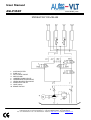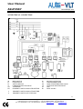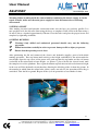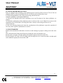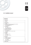
1
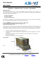
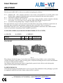
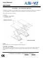
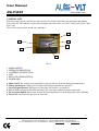
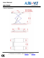
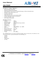
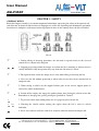
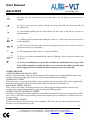
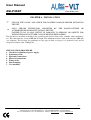
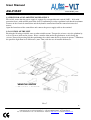
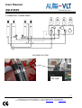
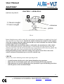
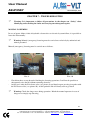
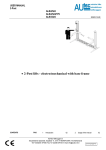
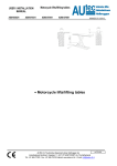
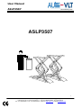
User Manual
ASLP3507
Issued: BG May, 2010
ASLP3507
1
AUTEC - VLT Automotive Equipment (divisie van Autec Hefbruggen bv)
Industrieterrein IJsselveld, Vlasakker 11, 3417 XT MONTFOORT, The Netherlands
Tel: +31 348 477000 - Fax: +31 348 475104 - Internet: www.autec.nl - E-mail: [email protected]
User Manual
ASLP3507
Issued: BG May, 2010
CONTENTS
FIRST PART
CHAPTER 1. INTRODUCTION-PACKING-TRANSPORT
CHAPTER 2. MACHINE DESCRIPTION
CHAPTER 3. SAFETY
CHAPTER 4. INSTALLATION
CHAPTER 5. OPERATION
CHAPTER 6. MAINTENANCE
CHAPTER 7. TROUBLESHOOTING
CHAPTER 8. ACCESSORIES
CHAPTER 9. DECLARATION OF CONFORMITY
page 3
page 5
page 9
page 11
page 18
page 19
page 20
page 23
page 24
SYMBOLS
.................................................................... HAZARD – DANGER
................................................................................ PROHIBITED
................................................................................... WARNING
Follow the instruction given by the messages preceded by a safety alert symbol !
2
AUTEC - VLT Automotive Equipment (divisie van Autec Hefbruggen bv)
Industrieterrein IJsselveld, Vlasakker 11, 3417 XT MONTFOORT, The Netherlands
Tel: +31 348 477000 - Fax: +31 348 475104 - Internet: www.autec.nl - E-mail: [email protected]
User Manual
ASLP3507
Issued: BG May, 2010
CHAPTER 1 - INTRODUCTION - PACKING – TRANSPORT
INTRODUCTION
This instruction manual has been created for workshop personnel using lifts and for ordinary and
extraordinary maintenance technicians. The manual must be read before proceeding with operating the lift
and contains important information for:
-
the safety of personnel;
the safety of the lift;
the safety of lifted vehicles.
This manual is an important part of the lift and must be kept where it is easily accessible for consultation
and we recommend particular attention in reading the chapter on safety.
The lift “ASLP3507” has been designed and built as required by:
EUROPEAN RECOMMENDATIONS: EEC 2006/42/CEE
EUROPEAN RULES:EN 1493
All operations of the lift must be carried out by skilled and authorised personnel, especially operations of
transportation, assembly, installation, maintenance, overhaul, moving, dismantling, etc. The manufacturer
cannot be held responsible for damages to persons, vehicles or objects caused by improper use of the lift.
Carefully read this instruction manual before using the lift.
The lift must be used only for lifting vehicles up to the specified capacity. Improper use of the lift
is forbidden.
Disconnect the lift from the main electric supply before carrying ordinary and extraordinary
maintenance operations.
The lift must be installed according to instructions.
PACKAGING
Pict. 1
3
AUTEC - VLT Automotive Equipment (divisie van Autec Hefbruggen bv)
Industrieterrein IJsselveld, Vlasakker 11, 3417 XT MONTFOORT, The Netherlands
Tel: +31 348 477000 - Fax: +31 348 475104 - Internet: www.autec.nl - E-mail: [email protected]
User Manual
ASLP3507
Issued: BG May, 2010
The lift model ASLP 3507 is delivered assembled and packaged as follows:
N° 2
N° 1
N° 1
N° 1
platforms (P1 – P2) complete with bases and scissors and positioned on wooden pallets with
wooden shims wrapped in pluriball plastic and closed with metal clips and relative gaskets.
control unit wrapped in pluriball plastic.
carton box containing the contol unit , set of short ramps (on-floor version) complete with tube
cover canals , or a set of space covers and four rubber pads H=40.set of space covers.
set of short or long lifting ramps, complete with tube cover canals.
For single deliveries (up to 3 units) the articles described above (long ramps excluded) are placed one on
top of the other and packed onto platforms with metal clips and relative seals (see picture 1).
For multiple deliveries (over 3 units) the packaging for the platforms remains the same whilst all other
articles are positioned and packaged onto europallets (picture 2).
PACKAGING SIZES (mm) FOR SINGLE DELIVERIES (UP TO 3 UNITS)
A: LENGTH
B: WIDTH
MODEL
ASLP3507
C: HEIGHT
A
1700
B
660
C
950
WEIGHT/KG
850
TRANSPORT
Pict. 2
The packages described in page 5 can be lifted and transported using forklifts, cranes or other lifting
systems of adequate capacity. Upon receiving goods, verify that no damage has been caused and that there
are all parts indicated on the checklist.
Any damages and/or missing parts must be immediately reported to the deliverer and subsequently
reported and documented to the manufacturer.
PACKING REMOVAL
All wooden packaging and pluriball plastic can be recycled. Total elimination of the packaging is possible
in compliance with the laws of the country where the lift is installed.
4
AUTEC - VLT Automotive Equipment (divisie van Autec Hefbruggen bv)
Industrieterrein IJsselveld, Vlasakker 11, 3417 XT MONTFOORT, The Netherlands
Tel: +31 348 477000 - Fax: +31 348 475104 - Internet: www.autec.nl - E-mail: [email protected]
User Manual
ASLP3507
Issued: BG May, 2010
CHAPTER 2 – MACHINE DESCRIPTION
ASLP3507 is a double scissor lift with free wheels designed and constructed for lifting cars of weight not
exceeding 3500 kg. It is equipped with extensions on platforms for also lifting longer vehicles.
The structure of the lift is as follows:
A. BASE
B. SCISSORS – PLATFORM
C. CONTROL UNIT
MOBILE STRUCTURE
FIXED STRUCTURE
Pict. 3
BASE
This is the fixed part of the lift equipped with floor-fixing holes.
SCISSORS – PLATFORM
This is the mobile and lifting part of the lift. It is made up of a series of arms and the upper platform all
fixed together by rotating pins on self-lubricating bushes. The mobile parts move on Teflon sliding
blocks.
5
AUTEC - VLT Automotive Equipment (divisie van Autec Hefbruggen bv)
Industrieterrein IJsselveld, Vlasakker 11, 3417 XT MONTFOORT, The Netherlands
Tel: +31 348 477000 - Fax: +31 348 475104 - Internet: www.autec.nl - E-mail: [email protected]
User Manual
ASLP3507
Issued: BG May, 2010
CONTROL UNIT
The unit is made up of a metallic box that contains all electrical, hydraulic and pneumatic functioning
parts of the lift. The controls are placed on the upper part of the unit, are of 24 V voltage and of the “dead
man” type.
There is one main control switch and a touchpad .
2
4
1
5
3
6
Pict. 4
1. MAIN SWITCH
2. LIFTING PUSH BUTTON
3. LOWERING PUSH BUTTON
4. LED
5. RE-ACTIVATION BUTTON
6. POWER LED
1. Main switch: The switch can be padlocked to prevent the use of the lift during the maintenance.
2. Lifting push button: When pressed, motor and lifting mechanism are operated.
3. Lowering push button: When pressed, lowering electrovalves are operated.
4. Led: It flashes during the final lift lowering at the same time with the acoustic transponder.
5. Re-activation button: This button restarts the lowering button (2) for the final phase under 250 mm.
6. Power led: it indicates the presence of electricity.
6
AUTEC - VLT Automotive Equipment (divisie van Autec Hefbruggen bv)
Industrieterrein IJsselveld, Vlasakker 11, 3417 XT MONTFOORT, The Netherlands
Tel: +31 348 477000 - Fax: +31 348 475104 - Internet: www.autec.nl - E-mail: [email protected]
User Manual
ASLP3507
Issued: BG May, 2010
OVERALL DIMENSIONS
7
AUTEC - VLT Automotive Equipment (divisie van Autec Hefbruggen bv)
Industrieterrein IJsselveld, Vlasakker 11, 3417 XT MONTFOORT, The Netherlands
Tel: +31 348 477000 - Fax: +31 348 475104 - Internet: www.autec.nl - E-mail: [email protected]
User Manual
ASLP3507
Issued: BG May, 2010
TECHNICAL CHARACTERISTICS
•
Electric-hydraulic functioning
•
Hydraulic synchronism of platforms
•
Safety hydraulic circuit (in case of accidental breakage or failure of hydraulic tubes)
•
Hydraulic safety using parachute valve
•
Overload security valve
•
Lowering control valve
•
Manual lowering device in case of power failure
•
Acoustic-light signal for final lowering phase
•
Inductive proximity sensors
•
Low voltage controls (24V)
TECHNICAL DATA
Capacity:
•
Maximum height:
•
Platform length:
•
Platform width:
•
Lifting time:
•
Lowering time:
•
Motor:
•
Noise level:
•
Exercise temperature:
•
Maximum pressure:
•
Maximum amperage:
•
Weight:
•
3500 kg
1910 mm
2000 mm when using extension
640 mm
50 sec
45 sec
3 PH 240/400 V 3 kw 50 HZ
< 74 db
-10° / +50°
300 bar
8A
850 ÷ 900 kg
The ASLP3507 lift has been designed and built for lifting vehicles in closed areas. Any other use is not
advised and the lift is especially unsuitable for the following uses:
- washing
- painting
- hoisting
- lifting people
- pressing
8
AUTEC - VLT Automotive Equipment (divisie van Autec Hefbruggen bv)
Industrieterrein IJsselveld, Vlasakker 11, 3417 XT MONTFOORT, The Netherlands
Tel: +31 348 477000 - Fax: +31 348 475104 - Internet: www.autec.nl - E-mail: [email protected]
User Manual
ASLP3507
Issued: BG May, 2010
CHAPTER 3 - SAFETY
GENERAL RULES
Read this chapter carefully as it contains important information concerning the safety of the operator and
risks that may be incurred with incorrect or improper use of the lift. Operating and maintenance personnel
must observe workplace accident prevention legislation in force in the country where the lift is installed.
Pict. 6
1. During lifting or lowering operations, the lift must be operated only in the reserved
control area as shown in the diagram.
2. Stopping or passing within the danger area when the lift is working or already raised is
strictly forbidden. Only the operator may stay under the lift when it is raised.
3. The operator must ensure the danger area is clear when lifting or lowering the lift.
4. Never use the lift without protection or when safety devices have been switched off or
tampered with.
5. When raising a vehicle use the supplied rubber pads on the correct support points as
advised by vehicle manufacturer.
6. Switch off the engine and engage the parking brake after placing the vehicle on the lift.
Remember to disengage the gear by placing the gearshift to “neutral”.
7. To prevent vehicle from falling make sure it is properly placed on the lift.
8. Entering the vehicle and/or starting the engine when the lift is raised is strictly
forbidden.
9. Never leave objects under the vehicle or scattered around it whilst lowering the lift.
9
AUTEC - VLT Automotive Equipment (divisie van Autec Hefbruggen bv)
Industrieterrein IJsselveld, Vlasakker 11, 3417 XT MONTFOORT, The Netherlands
Tel: +31 348 477000 - Fax: +31 348 475104 - Internet: www.autec.nl - E-mail: [email protected]
User Manual
ASLP3507
Issued: BG May, 2010
10. Keep the area around the lift clean and remove any oil spills to avoid the risk of
slipping.
11. Never use jets of water, steam, varnish or solvents in the lift areas around the lift and
the control unit.
12. Non-suitable lighting may be risky. Ensure all areas next to the lift are well lit in a
uniform manner.
13. Climbing on the platform when lifting the vehicle or when it has already been raised is
strictly forbidden.
14. Any use of the lift other what it has been designed for may cause serious accidents to
people and objects in its proximity.
15. The tampering of safety devices is strictly forbidden.
16. Never exceed the maximum lifting capacity (3500 kg). Check weight of vehicles that
are loaded.
17. In case of malfunction, stop the lift and block the on/off button by using a lock.
Only skilled technicians should be allowed to restart the lift. Make sure the main
power supply has been switched off before repairing and servicing the lift.
SAFETY DEVICES
ANTI-SHEARING AND FOOT SAFETY
The lift is provided with a safety device that automatically stops lowering at approximately 40 cm from
the floor. An acoustic-light signal is also activated during the final part of lowering.
HYDRAULIC SAFETY
This safety device is made up of parachute valves positioned inside the pistons. The valves automatically
block the lowering of the lift in case the hydraulic tubes are broken or accidentally cut.
DEAD-MAN SAFETY DEVICE
The car-lift is fitted with a dead-man control device. Releasing push button controls situated on the
console of the control unit immediately stops lowering and lifting operations.
DOUBLE CIRCUIT HYDRAULIC SAFETY
The lift has an independent double hydraulic system. Each circuit has the capacity to support the load but
not to raise it. This allows for positioning and/or lowering the load even when there is a failure in one of
the two circuits.
OVERLOADING SAFETY
The lift is fitted with a maximum valve for overloading. This valve does not allow for lifting when the
load has exceeded maximum capacity.
10
AUTEC - VLT Automotive Equipment (divisie van Autec Hefbruggen bv)
Industrieterrein IJsselveld, Vlasakker 11, 3417 XT MONTFOORT, The Netherlands
Tel: +31 348 477000 - Fax: +31 348 475104 - Internet: www.autec.nl - E-mail: [email protected]
User Manual
ASLP3507
Issued: BG May, 2010
CHAPTER 4 - INSTALLATION
UNPACK THE GOODS AND CHECK FOR POSSIBLE DAMAGE BEFORE INSTALLING
THE LIFT.
ONLY SKILLED TECHNICIANS APPOINTED BY THE MANUFACTURER OR
AUTHORISED DEALERS MUST INSTALL THE LIFT.
FAILURE TO DO SO MAY RESULT IN DAMAGES TO PERSONS OR OBJECTS FOR
WHICH THE MANUFACTURER CANNOT BE HELD RESPONSIBLE.
The lift must be installed according to the specified safe distance from walls, columns, other machinery,
etc. The room must be at least 4500 mm in height. The minimum distance from walls must be 2000 mm
(see diagram). The lift may be positioned on any type of floor as long as it is perfectly level and of
adequate resistance (min. 250 kg/cm²).
INSTALLATION PROCEDURE
1. Check for availability of power supply.
2. Positioning of lift.
3. Hydraulic connections.
4. Electrical connections.
5. Fixing of lift.
6. Initial running.
7. Use suitability
11
AUTEC - VLT Automotive Equipment (divisie van Autec Hefbruggen bv)
Industrieterrein IJsselveld, Vlasakker 11, 3417 XT MONTFOORT, The Netherlands
Tel: +31 348 477000 - Fax: +31 348 475104 - Internet: www.autec.nl - E-mail: [email protected]
User Manual
ASLP3507
Issued: BG May, 2010
1) CHECK FOR AVAILABILITYF POWER SUPPLY
First of all, ensure that the power supply is equipped by a magnet/thermic switch (380V – 16A) with
protection fuses) with suitable protection devices conforming to safety regulations and that the maximum
distance of the electrical connections and the hydraulic connections from the control unit must be 3
metres.
Open the front door of the control box and connect the power supply cable to the terminal.
2) LOCATION OF THE LIFT
Position the lift using a forklift, crane or other suitable means. To open the scissors, raise the platform by
at least 70 cm as indicated in picture . Place a wooden shim under the platform to avoid closing the
scissors. Proceed by moving and then positioning the vehicle onto the lift as shown in picture 7. Eliminate
the possible slight floor level differences (max 7mm) with the use of metallic thicknesses.
VEHICLE
VEHICLEENTRY
ENTRY
Pict. 7
12
AUTEC - VLT Automotive Equipment (divisie van Autec Hefbruggen bv)
Industrieterrein IJsselveld, Vlasakker 11, 3417 XT MONTFOORT, The Netherlands
Tel: +31 348 477000 - Fax: +31 348 475104 - Internet: www.autec.nl - E-mail: [email protected]
User Manual
ASLP3507
Issued: BG May, 2010
3) HYDRAULIC CONNECTIONS
BLEEDING SYSTEM
Oil tank
13
AUTEC - VLT Automotive Equipment (divisie van Autec Hefbruggen bv)
Industrieterrein IJsselveld, Vlasakker 11, 3417 XT MONTFOORT, The Netherlands
Tel: +31 348 477000 - Fax: +31 348 475104 - Internet: www.autec.nl - E-mail: [email protected]
User Manual
ASLP3507
Issued: BG May, 2010
HYDRAULIC DIAGRAM
1.
2.
3.
4.
5.
6.
7.
8.
9.
10.
SUCTION FILTER
PUMP 5 LT
FULL FORCE VALVE
MOTOR 3KW
UNIDIRECTIONAL VALVE
LOWERING ELECTROVALVE
LEVELLING ELECTROVALVE
PARACHUTE VALVE
HOLE 0.5mm
BRAKE PISTON
14
AUTEC - VLT Automotive Equipment (divisie van Autec Hefbruggen bv)
Industrieterrein IJsselveld, Vlasakker 11, 3417 XT MONTFOORT, The Netherlands
Tel: +31 348 477000 - Fax: +31 348 475104 - Internet: www.autec.nl - E-mail: [email protected]
User Manual
ASLP3507
Issued: BG April, 2010
4) ELECTRICAL CONNECTION
IN
F1
Z1
Y1
TA
FB
MAIN SWITCH
FUSE 5x20 1A
SAFETY MOTOR
LOWERING ELECTROVALVE
TOUCHPAD
PROXIMITY SWITCH HIGH STROKE END
3
4
PROXIMITY SWITCH HIGH STROKE END
PROXIMITY SWITCH OF LEVELLING
K1
T1
PU
Y2
SL
R1
MOTOR CONTACTOR
TRANSFORMER 70VA
HIGH STROKE END EXCLUSION
LEVELLING ELECTROVALVE
LED
RELE’ 24V DC
15
AUTEC - VLT Automotive Equipment (divisie van Autec Hefbruggen bv)
Industrieterrein IJsselveld, Vlasakker 11, 3417 XT MONTFOORT, The Netherlands
Tel: +31 348 477000 - Fax: +31 348 475104 - Internet: www.autec.nl - E-mail: [email protected]
User Manual
ASLP3507
Issued: BG April, 2010
Warning: Before working inside the control unit for connecting the electric supply or for the
repair of faults, make sure the main power supply has been disconnected to avoid being
electrocuted.
5) FIXING OF LIFT
After making electrical and hydraulic connections make sure the bases are perfectly parallel. It is
now possible to fix the lift to the floor using the bases as templates. Drill a hole in the floor using a
16 mm ∅ bit to a depth of approximately 150 mm. Clean the holes and place the proper inserts and
complete by tightening with bolts.
6) INITIAL RUNNING
Warning! Only skilled and authorised personnel should carry out the following
operations.
Follow instructions carefully in order to prevent damage to lift or injury to persons.
Ensure that the operating area is clear.
After positioning the lift and connected the electric and hydraulic supplies, proceed with initial
running operations. Press up button until arriving at the height established by the microswitch for
max height. Open the top cover of the power unit; push together the up button and the red button
(exclusion of the microswitch of amx height– see picture 1) placed beside the electric board, until
the complete rise of the platforms. Press again the buttons up and microswitch exclusion max height
in the way to fill the hydraulic circuit therefore allowing the bleeding of the air from the pistons. In
the moment in which from the unload tube (white) comes out only oil, the operation of bleeding is
concluded. Take the lift to ground. Repeat all the cycle of operations at least another 2 times.
16
AUTEC - VLT Automotive Equipment (divisie van Autec Hefbruggen bv)
Industrieterrein IJsselveld, Vlasakker 11, 3417 XT MONTFOORT, The Netherlands
Tel: +31 348 477000 - Fax: +31 348 475104 - Internet: www.autec.nl - E-mail: [email protected]
User Manual
ASLP3507
Issued: BG April, 2010
6A) PISTON BRAKE REGULATION
Lifts are equipped with a braking system which operates in the last 10 cm of travel. In case the two
platforms won’t go down synchronized in the last 10 cm, please follow these steps:
1) Check which platform is the slower in lowering with no load on
2) Put the platforms at an height of 20/30 cm
3) Unscrew the blocking nut of the regulation screw (on P1 piston of the slower platform, see
picture)
4) Check the synchronism of the platforms in the last 10 cm of the travel. Work if necessary on the
regulation screws of the brake (screwing will reduce velocity, unscrewing will increase it).
5) Screw the nut
6) Press the lowering button and check the synchronism of the platforms, repeat the operation if
necessary until a perfect synchronism is reached.
7) USE SUITABILITY
Follow with attention the indications in order to avoid damages to people or things and to the same
lift.
Once effectuated the fixing of the lift proceed with the static and dynamic tests.
For the static test apply a weight equal to the nominal capacity increased of the 25%
For the dynamic test, some cycles of lifting and lowering have to be carried out with a weight equal
to the nominal capacity increased of the 10%
17
AUTEC - VLT Automotive Equipment (divisie van Autec Hefbruggen bv)
Industrieterrein IJsselveld, Vlasakker 11, 3417 XT MONTFOORT, The Netherlands
Tel: +31 348 477000 - Fax: +31 348 475104 - Internet: www.autec.nl - E-mail: [email protected]
User Manual
ASLP3507
Issued: BG April, 2010
CHAPTER 5 - OPERATION
DRIVING SEQUENCE
1
2
1: Greater weight
2: lower weight
extension
piston
Pict. 8
Before lifting/lowering vehicles on the lift, ensure that the two platforms are completely closed and
that extensions have been inserted. Position the vehicle so that greater weight is on the opposite
side of the extension. Place the vehicle onto the lift very slowly and make sure that the vehicle
is properly positioned on the platforms.
Position rubber pads into the lifting points as indicated by the manufacturer of the vehicle.
Press the lifting button until the required height is reached and the lowering button to bring the
platforms back down. The lift will automatically stop at approximately 30 cm from the ground. The
acoustic-light signal will be then activated for the last lowering phase.
During the initial operations of the lift cracking noises may be heard. This is due to the
natural settlement of mechanical parts and will eventually stop.
CHECKS
Always carry out the following checks when operating the lift:
•
•
•
Carefully monitor the lift and its load during lifting/lowering operations.
Make sure the acoustic-light signal works correctly during the lowering main lift.
If the platforms are not level during these first operations, repeat air-bleeding procedures
with the pistons at their maximum height.
18
AUTEC - VLT Automotive Equipment (divisie van Autec Hefbruggen bv)
Industrieterrein IJsselveld, Vlasakker 11, 3417 XT MONTFOORT, The Netherlands
Tel: +31 348 477000 - Fax: +31 348 475104 - Internet: www.autec.nl - E-mail: [email protected]
User Manual
ASLP3507
Issued: BG April, 2010
CHAPTER 6 – MAINTENANCE
WARNING! Only authorised personnel must carry out maintenance. During maintenance
operations it is important to follow instructions in the chapter “SAFETY” and ensure that all
steps are taken to avoid accidental starting of lift.
PERIODIC MAINTENANCE
In order to keep the lift in peak condition, it is important to carry out periodic maintenance. The
manufacturer’s guarantee does not cover failure to do so.
•
•
•
•
•
The lift must be cleaned at least every 30-40 days. Do not use aggressive chemical products or
high pressure washing guns for cleaning.
Lubricate the sliding blocks and relative roller slideways periodically with grease.
Periodically check safety devices for proper working conditions.
Check high pressure hydraulic tubes once a year.
Check the oil level inside the tank every 3-4 months. Oil must be completely changed at least
every 3 years.
WARNING! Used oil is a highly polluting product. Always dispose of used oil according to
laws of the country where the lift is installed.
WARNING! Brake oil must be immediately removed as it is immediately corrosive for the
varnish. The piston stem must be protected from impurities that may cause damages or
prematurely wear out or even break the internal gaskets of the piston.
DEMOLITION
Only authorised and specialised technicians should proceed with the demolition of the lift.
Follow all precautions as specified in the chapter on “Safety”. Metallic parts can be scrapped as
“scrap iron”.
All other materials must be disposed of according to laws of the country where the lift is installed.
For fiscal purposes, all demolition operations must be properly documented according to laws of the
country where the lift is installed at the time of demolition.
19
AUTEC - VLT Automotive Equipment (divisie van Autec Hefbruggen bv)
Industrieterrein IJsselveld, Vlasakker 11, 3417 XT MONTFOORT, The Netherlands
Tel: +31 348 477000 - Fax: +31 348 475104 - Internet: www.autec.nl - E-mail: [email protected]
User Manual
ASLP3507
Issued: BG April, 2010
CHAPTER 7 – TROUBLESHOOTING
Warning: It is important to follow all precautions in the chapter on “Safety” when
identifying and searching for faults and carrying out subsequent repairs.
MANUAL LOWERING
In case of power failure, faults in hydraulic electrovalves or electrical system failure, it is possible to
lower the lift manually.
Warning: Manual (emergency) lowering must be carried out exclusively by authorised and
trained personnel.
Manual (emergency) lowering must be carried out as follows:
Pict. 9
-
Pict. 10
Check that there are no obstacles blocking the lowering operations. It will not be possible to
subsequently raise the lift without removing obstacles.
At first press only the EA electro-valve (see picture 9) and then keep on pressing it together with
the EO electro-valve (see picture 10). At this point the lift will slowly start to go down
Warning: Check the danger area during operation. Block the manual operators in case of
danger or to simply stop lowering.
20
AUTEC - VLT Automotive Equipment (divisie van Autec Hefbruggen bv)
Industrieterrein IJsselveld, Vlasakker 11, 3417 XT MONTFOORT, The Netherlands
Tel: +31 348 477000 - Fax: +31 348 475104 - Internet: www.autec.nl - E-mail: [email protected]
User Manual
ASLP3507
Issued: BG April, 2010
TROUBLESHOOTING
SYMPTOM 1
When pressing the lifting button, the lift does not move (the motor does not run).
POSSIBLE CAUSES 1
A. Lack of power supply to the electric card and the transformer.
Remedy – Check the relative fuse. Replace if fuse is blown.
B. Touchpad does not work.
Remedy – Check touchpad with a tester and replace if faulty.
C. Defective electric card.
Remedy – Check if relays and leds are activated when pushing buttons on the touchpad.
D. Uncertain connections between electric card and contactor; motor protector; valves.
Remedy – Check connections between electric card and contactor; motor protector; valves.
Replace faulty parts.
E. Photocell does not work.
Remedy – Check that photocell and relative connections are correct. Replace photocell if faulty.
F. Lifting limit switch does not work.
Remedy – check lifting limit micro and ensure connections are correct. Replace if faulty.
SYMPTOM 2
When pressing the lifting button, the lift does not move (the motor runs).
POSSIBLE CAUSES 2
A. Counter clockwise rotation.
Remedy – Invert the power supply phases of the motor if necessary.
B. Lack of oil.
Remedy – Check there is enough oil in the tank.
C. The lowering electrovalve on the hydraulic block remains open.
Remedy – Check if opening is due to a mechanical fault or magnet stimulation. Replace faulty
parts.
D. Maximum pressure valve broken.
Remedy – Tighten valve fully and turn back 1 and ½ turns. Retest the lift and replace valve if
problem persists.
E. Flexible hose connecting the pump and the hydraulic block is broken or loose.
Remedy – Check the hose in the tank. Replace if broken.
SYMPTOM 3
The lowering button is pushed but lift does not move.
POSSIBLE CAUSES 3
A. Follow instructions for step 1, lifting limit switch excluded.
Remedy – Follow remedy instructions for step 1.
SYMPTOM 4
The lifting button is pushed but lift stops.
21
AUTEC - VLT Automotive Equipment (divisie van Autec Hefbruggen bv)
Industrieterrein IJsselveld, Vlasakker 11, 3417 XT MONTFOORT, The Netherlands
Tel: +31 348 477000 - Fax: +31 348 475104 - Internet: www.autec.nl - E-mail: [email protected]
User Manual
ASLP3507
Issued: BG April, 2010
POSSIBLE CAUSES 4
A. If the lift moves when pushing the yellow exclusion button and the lifting button
simultaneously, the lifting limit switch is faulty or incorrectly positioned.
Remedy – Check the correct position of the cam and the functioning of the micro switch.
Replace if faulty. (The micro should intercept the cam when the platform is at maximum
height).
B. The lift does not move when pushing the yellow exclusion button and the lifting button
simultaneously.
Remedy – Follow instructions in step 1.
SYMPTOM 5
The acoustic signal is activated during the lowering phase, but the lift has not yet reached 30 cm
from the floor.
POSSIBLE CAUSES 5
A. The microswitch for the photocell cut-out is faulty or incorrectly positioned.
Remedy – Check the correct position of the cam and the functioning of the micro. Replace if
faulty. (The micro should intercept the cam when the platform is about 30 cm from the floor).
SYMPTOM 6
The P1 platform is fully lowered while the P2 platform remains lifted.
POSSIBLE CAUSES 6
A. The levelling valve remains closed due to. The P1 levelling microswitch is positioned
incorrectly.
Remedy – Check the position of the microswitch on its support. Replace the micro if faulty.
B. The magnet of the levelling valve is not excited.
Remedy – Check if the valve opens by connecting 24V directly onto the magnet. Check the
functioning of the electric card and the connection of cable between magnet and the card.
C. The levelling valve on the hydraulic block remains closed.
Remedy – Check if electrovalve is blocked. Pull it out from the block and verify if inner
cylinder is free to move using a small pin. Replace the valve if the pin remains blocked.
SYMPTOM 7
The P2 platform is fully lowered while the P1 platform remains lifted.
POSSIBLE CAUSES 7
A. The lowering valve remains closed due to. The P2 levelling microswitch is positioned
incorrectly.
Remedy – Check the position of the microswitch on its support. Replace the micro if faulty.
B. The magnet of the valve is not excited.
Remedy – Check if the valve opens by connecting 24V directly onto the magnet. Check the
functioning of the electric card and the connection of cable between magnet and the card.
C. The lowering valve on the hydraulic block remains closed.
Remedy – Check if electrovalve is blocked. Pull it out from the block and verify if inner
cylinder is free to move using a small pin. Replace the valve if the pin remains blocked.
22
AUTEC - VLT Automotive Equipment (divisie van Autec Hefbruggen bv)
Industrieterrein IJsselveld, Vlasakker 11, 3417 XT MONTFOORT, The Netherlands
Tel: +31 348 477000 - Fax: +31 348 475104 - Internet: www.autec.nl - E-mail: [email protected]
User Manual
ASLP3507
Issued: BG April, 2010
CHAPTER 8 – ACCESSORIES
The following accessories may be supplied upon request:
-
Supplementary rubber pads set (H = 40 mm)
Supplementary rubber pads set (H = 60 mm)
Supplementary rubber pads set (H = 80 mm)
Floorextensionset for increased lifting height 135mm
Drive on/off ramps long (extreme low cars)
BA-RB40
BA-RB60
BA-RB80
BA-A8H/ASLP3507
BA-A8L/ASLP3507
23
AUTEC - VLT Automotive Equipment (divisie van Autec Hefbruggen bv)
Industrieterrein IJsselveld, Vlasakker 11, 3417 XT MONTFOORT, The Netherlands
Tel: +31 348 477000 - Fax: +31 348 475104 - Internet: www.autec.nl - E-mail: [email protected]
User Manual
ASLP3507
Issued: BG April, 2010
CHAPTER 9 – DECLARATION OF CONFORMITY
AUTEC Hefbruggen b.v.
Vlasakker 11
NL 3417 XT Montfoort
Nederland
Hereby declares that the lift:
ASLP3507
To which this declaration is related, conforms with the following European directives:
2006/42/CE
It also declares that the following European rules have been respected:
EN 1493
CE Certificate number: 0062.150X0454.06.06
24
AUTEC - VLT Automotive Equipment (divisie van Autec Hefbruggen bv)
Industrieterrein IJsselveld, Vlasakker 11, 3417 XT MONTFOORT, The Netherlands
Tel: +31 348 477000 - Fax: +31 348 475104 - Internet: www.autec.nl - E-mail: [email protected]