1
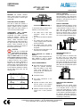
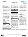
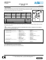
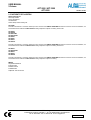
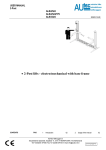
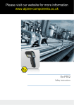
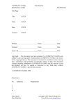
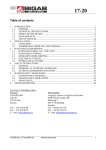
USER MANUAL
2-Column
APT-3000 / APT-3500
APT-5000
ISSUED 04-02-2004
• 2-Column vertical lifts
AUTEC Hefbruggen bv
Industrieterrein Ijsselveld, Vlasakker 11, 3417 XT MONTFOORT, The Netherlands
Tel:+31 348 477000 Fax:+31 348 475104 E-mail: [email protected]
en/TA-APT-3500-01
USER MANUAL
2-Column
APT-3000 / APT-3500
APT-5000
INDEX OF CONTENTS
1 Introduction
2 How to use this Manual
3 Description of the lift
4 Technical specifications
5 Safety
6 Controls and operation
7 Maintenance
8 Troubleshooting
9 Conformity Declaration
PAGE
02
02
02
03
03
05
07
07
08
1. INTRODUCTION
ability to explain the drawings and the
descriptions contained in this manual to
other people. At the same time he must
also be aware of the general and
specific safety regulations which apply
in the country where the lift is being
installed. The word “operator”, which
has been used throughout this manual,
refers to a person who is authorised to
use the platform. The minimum legal
age for using the lift is 18 years.
ISSUED 04-02-2004
CONTROL CABINET (Fig. 2)
The electrical control cabinet consists of
the following :
• Main switch (11)
• Lifting motion button (12)
• Lowering motion button (13)
3. DESCRIPTION OF THE LIFT
CAUTION
This Manual is intended for factory
personnel who are going to operate
the lift; read the Manual before you
use the platform in any way or
perform any actions on it. This
Manual
contains
important
information about the following
points :
n THE PERSONAL SAFETY OF THE
OPERATORS
n THE SAFETY OF THE LIFT
n THE SAFETY OF THE VEHICLES
LIFTED
2. INSTRUCTIONS FOR USE
The Manual forms part of the lift and
must be available for reference in the
immediate vicinity of the lift at all times.
The operator of the lift must be able to
refer to the Manual quickly and at any
given moment.
2 column electro-hydraulic column
vertical lift, models APT 3000, APT3500, APT-5000. These platforms are
embedded in the floor of the workspace
and are designed and manufactured for
lifting passenger cars and delivery vans
and to maintain them in this lifted
position.
The main components of the lift are :
• A steel case
• Hydraulic cylinders
• Electro-hydraulic pumping unit
• Safety arrangements
• Control cabinet
• Support chassis
In Fig. 1 you can see how the various
parts come together to form a lift.
SAFETY ARRANGEMENTS
n Non-return valves in the valve block
which are operated electrically.
When the voltage is cut-off, these
valves close automatically and
prevent the lift from sinking back to
the original position.
n Overpressure valve
n Arm locking mechanisms on the
support arms.
n Hydraulic non-return valves which
limit the speed of the lowering
motion in the case of hose rupture.
IT IS STRONGLY RECOMMENDED THAT
YOU SHOULD FIRST CAREFULLY READ
THE SAFETY INSTRUCTIONS.
The manufacturer hereby refuses to
accept any responsibility for injury to
persons or damage to equipment or
property if it appears that incorrect
handling of the lift has taken place. This
instructions manual only describes the
operating- and safety aspects which
persons who are installing the machine
need to know. In order to understand
the terminology used in this manual, it is
necessary that the person performing
the installation work should have
specific experience in industrial work,
service, maintenance and repair
activities, and must also possess the
Fig. 2
n The torsion beam prevents the
support plate and the sliding tracks
from getting displaced or distorted.
In addition, if any of the cylinders
fail, these torsion bars transfer the
power to the cylinder which is still
working properly.
Fig. 1
n Electrical protection through fusible
cut-outs.
AUTEC Hefbruggen bv
Industrieterrein Ijsselveld, Vlasakker 11, 3417 XT MONTFOORT, The Netherlands
Tel:+31 348 477000 Fax:+31 348 475104 E-mail: [email protected]
en/TA-APT-3500-02
USER MANUAL
2-Column
APT-3000 / APT-3500
APT-5000
4. Technical specifications
APT 3000/P
Max. Load capacity
Max. Speed of lifting in cm/sec
Max. Speed of lowering in cm/sec
Operating pressure in bar
Pressure limitation in bar
Operating voltage in Volt
Control voltage of the valve in Volt
Control voltage for the electronic
components in Volt
Noise level in dB(A)
Limit switch for height limitation
Limit switch for downward movement
signalling
Pneumatic emergency lowering valve
Working environment
Motor power in Kw
Voltage in Volt
Frequency in Hz
Connected load
APT 3500/R
APT 3500/R1
APT 3500 R/WF
APT 3500 R1/WF1
APT 3500/K
APT 3500/P
ISSUED 04-02-2004
APT 3500/V
APT 3500/VL
APT 5000/R1/WF1
APT 5000/V
APT 5000/R
APT 5000/R1
3000 Kg
6,5
7,0
160
180
400
196
24
3500 Kg
6,5
7,0
180
200
400
196
24
5000 Kg
4,5
5,0
180
200
400
196
24
70
Yes
No
70
Yes
Yes
70
Yes
Yes
No
Covered
Yes
Covered
Yes
Covered
3
400
50
400V / 16A
3
400
50
400V / 16A
3
400
50
400V / 16A
WEIGHT AND SIZE OF THE VEHICLE
The lift can be used for practically all
vehicles provided that the maximum
loading capacity at the support points is
not exceeded.
Always take into account the lifting
capacity of the lift in the case of large
vehicles with special characteristics
(such as delivery vans, etc.).
The safety zone (Fig. 3) is determined
by the dimensions of the vehicle.
MAX.3000 kg APT 3000
MAX.3500 kg APT 3500
MAX.5000 kg APT 5000
5. SAFETY
It is important to read point number 5 of
this Manual properly since it contains
important information about the risks
which the operator of the lift will be
exposed to if the lift is not used
properly. In what follows, you will find
information about how to avoid
dangerous situations.
WARNING.
The lift is designed and
constructed to lift vehicles
and to hold them in a certain
position in a covered working place. Any
other form of use is not permitted. In
short, the lift is not suitable for the
following purposes :
n Washing and spraying work.
n To be used as a device for applying
force.
n To be used as a goods lift.
n To be used as a jack or for lifting
vehicles for changing wheels.
The manufacturer hereby refuses to
entertain any claims for damages
arising in connection with injury to
persons or damage to vehicle or other
property caused due to incorrect and/or
unauthorised use of the lift.
During lifting- and lowering movements,
the operator must be within the zone of
operation (1), as shown in Fig. 3. The
presence of any person in the danger
zone (2) is strictly forbidden. The
presence of persons under the vehicle
is only permitted if the vehicle is parked
in the lifted position.
USE THE LIFT ONLY IF ALL THE SAFETY
ARRANGEMENTS
ARE
WORKING
PROPERLY. IF THESE RULES ARE NOT
FOLLOWED, SERIOUS INJURY COULD
BE CAUSED TO PERSONS AS WELL AS
IRREPARABLE DAMAGE TO THE LIFT
AND THE VEHICLE ON THE LIFT.
GENERAL PRECAUTIONS
•
The operator is bound to follow the
regulations which apply in the
country in which these lifts are
installed.
In addition, the operator must :
•
•
•
Always work in the operator area as
designated in the manual.
Never remove the protective guards
or dismantle or shut down the
mechanical, electrical or other types
of safety arrangements or locks.
Read the safety regulations relating
to the lift and take cognisance of the
safety information provided in this
Manual.
The following terms have been used in
this Manual to describe the various
types of risk :
Fig. 3
RISK : this indicates a potential danger
which could lead to serious injury or
death.
AUTEC Hefbruggen bv
Industrieterrein Ijsselveld, Vlasakker 11, 3417 XT MONTFOORT, The Netherlands
Tel:+31 348 477000 Fax:+31 348 475104 E-mail: [email protected]
en/TA-APT-3500-03
USER MANUAL
2-Column
APT-3000 / APT-3500
APT-5000
RISKS TO PERSONS
This paragraph describes the risks to
which the operator or any other person
near the working area where the lift is in
operation, in case the lift is not used in
the appropriate manner.
WARNING: this indicates situations
and/or actions which are unsafe and
could lead to injuries of various types
except death.
RISKS AND PROTECTIVE MEDIA
The risks to which the operator is
exposed when the vehicle is in a raised
position, together with the protective
media which have been installed, in
order to limit the possible dangers.
LONGITUDINAL AND LATERAL
MOVEMENTS OF THE VEHICLE.
Longitudinal and lateral movements
include the following : forward- and
backward movements of the load (the
vehicle). Lateral movements include
displacement of the vehicle to the left or
the right, particularly during the lifting
process. These movements can be
prevented by positioning the vehicle on
the lift in the correct manner.
CAUTION
Do not try to move the
vehicle when it is on the lift.
The support part of the lift should
only be shifted when it is in the
lowest position and there is no load.
It is extremely important that the vehicle
is placed on the lift in such a manner
that there is an uniform distribution of
weight over the arms (Fig. 4). Try to
place the centre of gravity of the load as
far as possible in the centre of the lift.
For the maximum distribution of weight,
see the table shown below and the
drawing as well.
MAX. WEIGHT DISTRIBUTION
APT-3000
3
:
1800 Kg
2
1200 Kg
APT-3500
2
:
2333 Kg
1
1167 Kg
APT-5000
2
3333 Kg
:
1
1667 Kg
ISSUED 04-02-2004
Fig. 4
To ensure the safety of persons and of
materials, you must see to it that :
• The safety zone is kept under
observation during the lifting
process.
• The motor of the vehicle is switched
off.
• The vehicle must be lifted on the
car-jack support points as indicated
by the manufacturer.
• The support points of the vehicle,
and the lift must both be free of oil
and grease.
• Due account has been taken of all
the dimensions and weights.
RISKS INVOLVED IN LIFTING A
VEHICLE
The following safety arrangements have
been installed in order to prevent
damage due to overloading and faults :
SAFETY ARRANGEMENTS
n Non-return valves in the valve block
which are operated electrically.
When the voltage is cut-off, these
valves close automatically and
prevent the lift from sinking back to
the original position.
RISKS TO PERSONNEL
When the lift with the vehicle is moving
downward, it is not permissible for any
of the personnel to enter the room or
walk under the (downward) moving
parts of the lift (Fig. 5). The operator
should not start the motion of the lift
until he has assured himself that there
are no persons within the danger zone.
Fig. 5
DANGER ARISING DUE TO
COLLISIONS
This danger arises in connection with
the parts of the car or other vehicle
which are at head-height. If the lift is still
at a lower level, the personnel must
take care to see that they do not bump
into parts of the vehicle, the lift or other
parts, which are not marked with special
warning colours. (Fig. 6).
n Overpressure valve
n Arm locking mechanisms on the
support arms.
n Hydraulic non-return valves which
limit the speed of the lowering
motion in the case of hose rupture.
n Electrical protection through fusible
cut-outs and a motor protection
switch.
Fig. 6
RISKS INVOLVED IN MOVING A
VEHICLE
Movements may be caused during
activities which involve the application
of an adequate amount of force for
moving the vehicle (Fig. 7). In cases
where the vehicle being lifted is almost
of the maximum permissible weight or
the maximum permissible dimensions,
movements in the vehicle could lead to
overloading or unbalancing.
AUTEC Hefbruggen bv
Industrieterrein Ijsselveld, Vlasakker 11, 3417 XT MONTFOORT, The Netherlands
Tel:+31 348 477000 Fax:+31 348 475104 E-mail: [email protected]
en/TA-APT-3500-04
USER MANUAL
2-Column
APT-3000 / APT-3500
APT-5000
ISSUED 04-02-2004
RISKS ARISING DUE TO DEFECTIVE
COMPONENTS DURING USE
Autec uses material of the highest
quality in its lift. The use of these must
be made according to the standards,
and maintenance must be done
regularly.
Fig. 7
RISKS INVOLVED IN POSITIONING A
VEHICLE
This type of risk may arise if the vehicle
is not properly placed on the support
points (Fig. 8), or if the support arms
platforms are not properly aligned with
respect to the lift. One can avoid this by
always lifting the vehicle using the carjack support points as recommended by
the manufacturer, and which are
normally used for supporting car-jacks
while changing tyres, and to place the
vehicle as far as possible in the middle
of the platform.
6. CONTROLS / OPERATION
Fig. 10
Fig. 13
Fig. 11
Fig. 8
Never rest any fittings or other objects
against the columns and never place
such objects under the platform when it
has a load mounted on it, since this can
impede the lowering operations and
may cause the vehicle to fall off the
platform (Fig. 9).
RISK OF ELECTROCUTION
Never spray water or steam or solvents
or paint in the area immediately
surrounding the platform and the control
cabinet (Fig. 12).
Fig. 12
Fig. 9
Never enter the vehicle or start the
motor when the vehicle is on the lift
(Fig. 10).
The control cabinet consists of :
RISK OF SLIDING OUT
This risk can be overcome by avoiding
the spillage of oil or grease in the area
surrounding the lift (Fig. 11).
RISKS
ARISING
DUE
TO
INSUFFICIENT LIGHTING
The area surrounding the lift must be
well-lighted according to the legal
requirements applicable in the region or
country where the platform is installed.
Fig. 14
MAIN SWITCH (11)
Position 0 : In this position, the lift is no
longer live, and one may now open the
control cabinet. If necessary, a lock may
be placed on the main switch, so as to
prevent unauthorised access or
operation of the lift.
Position 1 : When the main switch
(11) is in the position “1”, one cannot
open the control cabinet.
LIFTING MOTION BUTTON (12)
This is a counter-sunk button which
must be kept pressed down during the
lifting process. (also called the 'dead
man's button').
LOWERING MOTION BUTTON (13)
This is a counter-sunk button which
must be kept pressed down during the
lowering process. (also called the 'dead
man's button').
WHEEL-FREE SYSTEM (14 Fig. 14)
In order to use the wheel-free system,
the WF button (14) must be pressed
simultaneously with the lifting motion
button (12), during the lifting process.
During the lowering motion, the
AUTEC Hefbruggen bv
Industrieterrein Ijsselveld, Vlasakker 11, 3417 XT MONTFOORT, The Netherlands
Tel:+31 348 477000 Fax:+31 348 475104 E-mail: [email protected]
en/TA-APT-3500-05
USER MANUAL
2-Column
APT-3000 / APT-3500
APT-5000
downward motion button (13) and the
WF button (14) must be pressed
simultaneously.
SEQUENCE OF OPERATIONS AND
POINTS OF IMPORTANCE
• The support points with which the
vehicles are to be lifted are the
same as the ones normally used
for applying conventional car-jacks.
In case of doubt, as to the location
of the car-jack support points,
please get back to your car
manufacturer or dealer.
• Before the car is positioned on the
lift, one should ensure that the lift
is in its lowest position.
• Sudden acceleration or application
of the brakes while the car is on
the support plates is not
permissible.
• In the case of low-slung (with the
chassis very close to the ground),
that no direct contact is made with
the lift.
• Take care to see that the support
points are free of oil or grease.
• In the case of wheel-free systems,
check that the car is positioned
properly.
• During the lifting and lowering
operations, it is not permissible
that persons are present in the
danger zone.
•
SUPPORT POINTS
APT-3500 / R / WF
APT-3500 / R1 / WF1
APT-5000 / R1 / WF1
Push the vehicle onto the support
plates. Now position the vehicle in the
centre of the plates for sliding cars onto
and down from the lift. A thumb rule
which applies is that the front wheel
comes to rest about 30 cm in front of
the wheel-less lifting plates. The wheelfree lifting plates can be pushed out
length-wise, on both sides. Push out the
plates until they are under the car-jack
support points recommended by the
manufacturer. Then use the rubber
support blocks supplied along with the
lift, for lifting the vehicle.
APT-3500 / R
APT-3500 / R1
APT-5000 / R
APT-5000 / R1
Push the vehicle onto the support
plates. Now position the vehicle in the
middle of the sliding plates.
APT-3000 / P
APT-3500 / P
Push the support plates out upto the
desired length. Move the vehicle in the
correct direction over the support plates.
Now position the rubber supports under
the car-jack support points of the
vehicle
as
specified
by
the
manufacturer. In case of doubt
regarding these car-jack support points,
consult the dealer or the manufacturer
of the vehicle.
APT-3500 V
APT-3500 / VL
APT-5000 V
Place the support arms along the length
of the support wheels. In other words,
place the support arms along the sliding
direction. The slide-through area is now
at its maximum. Slide the vehicle
between the arms. Position the vehicle
such that the distance between the
front- and the rear wheels is more or
less the same with respect to the centre
of the lift. Position the rubber supports
of the support arm under the car-jack
support points specified by the
manufacturer.
APT 3500 / K
Push in the support arm to the shortest
length possible. Now position the
ISSUED 04-02-2004
vehicle in the centre of the lift. Push the
support arms over the support beams
until they are in line with the car-jack
support points. With the left hand,
release the support arm locks. With the
right hand pull out the arm until the
support arm rubber comes to rest
exactly below the car-jack support point
specified by the manufacturer.
• LIFTING
Turn the main switch into position 1,
and press the lifting motion button.
Release the lifting motion button after
the vehicle has been lifted above the
ground level, and check whether the
vehicle is safely positioned on the lift. If
the vehicle is safely positioned, press
the lifting motion button until the desired
height is reached.
• PARKING
Release the lifting button when the
desired height is reached, and then turn
the main switch to the 0 position.
• LOWERING
First check whether there are any
obstacles under the lift, turn the main
switch in the position 1, press the
lowering motion button, in order to lower
the vehicle down to the desired height,
or down to the ground. In case of
lowering to ground level, the lift will be
stopped when it reaches a height of
about 120 mm above the ground, and
an acoustic signal is given. The signal
warns the user that he should first
ensure that the danger zone is
completely free of obstacles.
When the lowering motion button is
pressed again, the lift will be lowered
further, accompanied by a continuous
acoustic signal.
EMERGENCY LOWERING OF THE PLATFORM
If the powers gets interrupted, it is possible to lower the bridge, in the following manner : remove the centre plate. Hold the air hose and roll it
out. Supply the air hose with compressed air. Before doing this, take care to see that the safety zone is free of persons and/or objects. Some
types have a hole in the side of the control cabinet. Now supply the hole with compressed air.
AUTEC Hefbruggen bv
Industrieterrein Ijsselveld, Vlasakker 11, 3417 XT MONTFOORT, The Netherlands
Tel:+31 348 477000 Fax:+31 348 475104 E-mail: [email protected]
en/TA-APT-3500-06
USER MANUAL
2-Column
APT-3000 / APT-3500
APT-5000
ISSUED 04-02-2004
7. MAINTENANCE
The lift must be inspected once a year according to the CE Regulations, by a person who is certified to do the same. In addition, preventive
maintenance must also be carried out once a year on the lift (ask for AUTEC maintenance contracts).
We recommend the following lubricants for lubricating the lift :
No.
Texaco
Shell
ESSO
Castrol
1. Hinged joints in the arm
Molytex EP32
Alvania HDX-2
MS3
2. Lubricating nipples in
the guides
3. Hydraulic system
Molytex EP32
Alvania HDX-2
Rando 32
Tellus 32
Multipurpose +
moly
Multipurpose +
moly
Nutto H32
No.
1.
2.
3.
Lubricating points
Hinged joints in the support arms, if any + arm locks, if any
Lubricating nipples in the column guides
Replacement of hydraulic oil
MS3
HYSPIN HWS
32
Lubricating
interval
3 Months
1 year
5 years
Search for the source of the fault, and carry out the necessary repairs only after all the necessary SAFETY REGULATIONS as described
have been taken into account.
i
ALL “RESETTING” ACTIONS, REPAIRS TO THE SAFETY ARRANGEMENTS AND ELECTRICAL COMPONENTS IN THE LIFT MUST BE
CARRIED OUT BY AUTHORISED PERSONNEL ONLY.
PROBLEMS
POSSIBLE CAUSES
?
The lift does not move upward when the lifting button is
pressed (motor is not running)
?
The platform does not rise when the lifting motion button is
pressed (the motor is running)
?
The lift rises only partially
?
The lift comes down on its own
?
?
?
REMEDIAL ACTION
The lift does not come down although the lowering motion
button has been pressed
?
?
?
?
?
?
?
?
?
•
•
?
?
?
?
?
•
•
The fuse has burnt out
No power
Fault in the electrical system
Insufficient oil
?he hydraulic hose has ruptured
The relief valve has opened
?he overpressure valve is in operation
Leakage in the hydraulic circuit
Seal is not sealing properly
The thermal protection keeps tripping
The lifting bridge is overloaded
Voltage too low
Insufficient oil
Leakage in the airing valve
Relief valve is choked up
Relief valve is defective
Foreign object under the lifting table
Fault in the electrical system
?
?
?
?
?
?
?
?
?
•
•
?
?
?
?
?
?
?
Replace the fuse
Reconnect
Call up the Autec service department
Fill in oil
Replace the hose
Check/replace
Check the weight on the lift
Ring up AUTEC
Ring up AUTEC
Re-set the thermal protection
Maintain the weight according to the specifications
Check the voltage
Fill in oil
Ring up AUTEC
Clean the valve
Ring up AUTEC
Remove the foreign object
Ring up Autec service department
The pump makes a noise
Oil leakage in the cylinder
?
?
Oil is contaminated
The seal is damaged
?
?
Replace the oil
Ring up AUTEC
DETAILS REQUIRED WHILE CALLING AUTEC SERVICE.
If you are reporting a fault, try to provide at least the following data :
n The serial number, the type and the year of manufacture of the lift.
AUTEC Hefbruggen bv
Industrieterrein Ijsselveld, Vlasakker 11, 3417 XT MONTFOORT, The Netherlands
Tel:+31 348 477000 Fax:+31 348 475104 E-mail: [email protected]
en/TA-APT-3500-07
USER MANUAL
2-Column
APT-3000 / APT-3500
APT-5000
ISSUED 27-01-2004
9. CONFORMITY DECLARATION
AUTEC Hefbruggen b.v.
Waardsedijk Oost 8b
NL 3417 ZK Montfoort
The Netherlands
declares hereby that the following lifts :
APT-3000/P
have been manufactured in accordance with the provisions contained in the RWTUV GUIDELINES and that the lift conforms to the said Guidelines, and
have obtained the CE Certificate : 04 205-1342/98 after being subjected to inspection and testing. And also that :
APT 3500/R
APT 3500/R1
APT 3500 R/WF
APT 3500 R1/WF1
APT 3500/K
APT 3500/P
APT 3500/V
APT 3500/VL
have been manufactured in accordance with the provisions contained in the RWTUV GUIDELINES and that the lift conforms to the said Guidelines, and
have obtained the CE Certificate : 04 205-0577/98 after being subjected to inspection and testing. And also that
APT 5000/V
APT 5000/R1/WF1
APT 5000/V
APT 5000/R
APT 5000/R1
have been manufactured in accordance with the provisions contained in the RWTUV GUIDELINES and that the lift conforms to the said Guidelines, and
have obtained the CE Certificate : 04 205-1343/98 after being subjected to inspection and testing.
RWTUV
Langemarckstrasse 20
D-45141 Essen
Postfach 1032 61
D-45032 Essen
Telephone +49 / 201 8 25-0
AUTEC Hefbruggen bv
Industrieterrein Ijsselveld, Vlasakker 11, 3417 XT MONTFOORT, The Netherlands
Tel:+31 348 477000 Fax:+31 348 475104 E-mail: [email protected]
en/TA-APT-3500-08