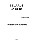
1
MTZ
2022
2022V
2022-0000010РЭ
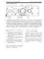
OPERATION MANUAL
Operation manual has been compiled by V.G. Levkov, engineer of Headquarters Specialized Design
Office
Editor-in-Chief – Chief Designer - M.G. Meleshko
Supervisor for the Issue – Chief, Design Office
Bobrovnik A.I., (DTecn.Sci.)
Tractors MTZ 2022/2022V. Operation manual / V.G.Levkov/
The Operation Manual contains description and technical specification of tractors MTZ 2022/2022V
manufactured by Minsk Tractor Works.
Main procedures of machines’ maintenance are set forth, adjustment and servicing data are given.
The Manual is intended for tractor operators engaged in the operation and maintenance of MTZ tractors.
As the policy of MTZ is aimed at the constant improvement of machines under manufacture, changes in
the design of some components, not elucidated in the present edition, may be introduced. Address your
local “MTZ” dealer for more details.
© Minsk Tractor Works RUE, 2003
All rights reserved. The book shall not be reproduced or copied fully or in part without written
permission of Minsk Tractor Works RUE.
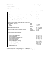
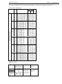
Contents
Introduction
1. Safety regulations
2. General data
3. Technical data
4. Controls and instrumentation
5. Arrangement and operation of tractor’s components
6. Tractor pre-starting procedure
7. Tractor ganging-up
8. Transportation and towing
9. Scheduled maintenance
10. Storage
11. Supplements
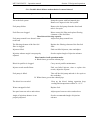
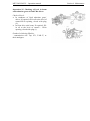
Possible malfunctions and correction procedures:
- diesel engine
- clutches
- gear box
- rear axle
- rear PTOS
- FDA
- brakes
- pneumatic system
- HTDS
- malfunction diagnosis
- major malfunctions
- average malfunctions
- minor malfunctions
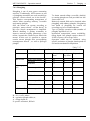
5
13
17
27
46
152
158
185
186
218
219
62
71b
78
83
88
99
113
118
125
137
139
141
142
MTZ 2022/2022V
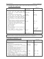
To attention of operators
TO ATTENTION OF OPERATORS!
1. Before starting the tractor, carefully study the present manual and strictly observe all operation and
maintenance directions.
2. Be sure to run-in the tractor for 30 hours. Before the first maintenance (125 hours) load diesel up to
80% of rated power.
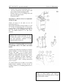
3. Your tractor is equipped with range gear box. Ranges are shifted by means of tooth-type couplings
and synchronizers, and gears within each range are selected by synchronizers.
First the range is shifted, then the gear is put in.
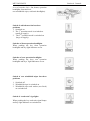
TO SHIFT THE RANGE:
-
press the clutch pedal and wait until tractor comes to a full stop;
using the range shifting lever, smoothly and without jerks shift the required range; ranges are shifted
according to recommendations given in section “Tractor pre-starting procedure”.
TO PUT IN GEAR:
-
press the clutch pedal;
smoothly and without jerks pull the gear shifting lever and hold it pressed until the gear is fully put
in;
- smoothly release the clutch pedal.
Change gears on the go within one range only during transport works on hard roadway covering. DO
NOT shift gears when moving in cross-country conditions (ploughed field, sand soil, peat terrain) due to
abrupt stops. In this case move on such terrain using the earlier put in gear. Non-observance of these
regulations will result in premature wear of tooth-type coupling pinion’s splines, as well as damage of
synchronizers.
CAUTION! If, with clutch pedal pressed, ranges and gears are put in with grinding sound,
immediately consult your local dealer and correct malfunction.
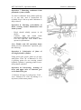
4. Observe rules of PTOS engagement. To avoid damage of the shaft, reduction gear pinions and PTOS
during PTOS switching, pull steering lever smoothly with travel delay by 2…4 starting from the middle
of travel from neutral to PTOS switch.
5. The operating and parking brakes should be adjusted only on horizontal ground with the engine shut
down and wedges placed from the front and behind rear wheels to avoid accidental movement of the
tractor.
6. The tractor shall not be operated without a storage battery in the electrical equipment.
MTZ 2022/2022V
Introduction
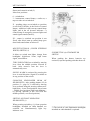
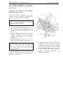
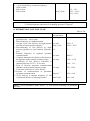
INTRODUCTION
The present manual contains description of the design, technical data, directions for operation and
maintenance of agricultural high-power wheeled tractors MTZ 2022 and MTZ 2202V (reversible
model).
Tractor MTZ 2022 has 4×4 wheel arrangement and has been designed for performing various
agricultural works using mounted, half-mounted and trailing machines and implements, for
transportation, using loading-unloading mechanisms, harvesting complexes, as well as for driving
stationary agricultural machines.
Tractor MTZ 2022V is a reversible model, designed for prolonged operation in the reverse mode.
The difference lies in the additional reversible steering post that includes an additional steering column,
duplicate transmission control, brakes, fuel supply system, as well as special reversible seat to be used
for direct and reverse movement.
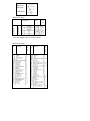
Abbreviations and symbols:
DAI
SB
DL
TDC
PTOS
HTDS
RLM
HLS
CL
GB
TC
M
DSM
IVR
PIS
FDA
TCM
- differential automatic interlock;
- storage battery;
- differential lock;
- top dead center;
- power take off shaft;
- hydraulic three-dimensional steering;
- rear lift mechanism;
- hydraulic lift mechanism;
- clutch;
- gear box;
- turbo-compressor;
- maintenance;
- daily shift maintenance;
- integral voltage regulator;
- power intake shaft;
- front drive axle;
- traction-coupling mechanism;
UCS - universal control system of agricultural machinery;
FPTOS- front power take off shaft;
HPH - high-pressure hose;
MTA - machine-tractor assembly;
SPK - spare parts, tools and appliances kit;
SAC - supercharged air cooler;
SCU - starter control unit;
ILCU - incandescent lamps control unit
MTZ 2022/2022V
Introduction
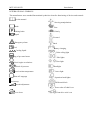
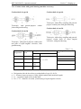
INTERNATIONAL SYMBOLS
The manufacturer uses standard International symbols to describe functioning of devises and controls.
See the manual
Steering manipulations
Brake
Fast
Parking brake
Slowly
Signal
Forward
Emergency alarm
Fuel
Cooling liquid
Back
Battery charging
Cabin ceiling light
Plug of pre-start heater
Diesel engine revolutions
diesel oil pressure
Diesel coolant temperature
Shut-off/ stoppage
On/start up
Side lights
Turn light
Headlight
Lower light
Operation head-lights
Differential lock
Smooth adjustment
Power take off shaft is on
Lever down
Front drive axle is on
MTZ 2022
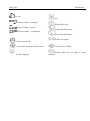
Introduction
Lever up
Fan
External cylinder “ extending”
Wind shield wiper
External cylinder “ pull-in”
Front wind shield wiper
External cylinder “ equilibrium”
Rear wind shield wiper
Trailer turn signal
Oil pressure in KP
Air pressure in the pneumatic system
Air filter clogging
Oil pressure in HTDS
Braking fluid level in tanks of main
cylinders
MTZ 2022/2022V
Section 1. Safety regulations
1. SAFETY REGULATIONS
1.1 GENERAL PROVISIONS
1.1.1 Strict observance of regulations ensures tractor operating safety, improves its reliability and
increases operation life.
1.1.2 The tractor can be operated by at least 17-yers old persons who received tractor operator
license and passed occupational and fire safety tests.
1.1.3 Carefully study the present manual before using the tractor. Insufficient knowledge of
tractor control and maintenance can be the reason of accidents.
1.2
SAFETY REQUIREMENTS IN TRANSPORTATION AND REACTIVATION
1.2.1 During transportation and loading/unloading operations follow directions set forth in section
8.
1.2.2 In preserving the tractor and additional equipment follow requirements for fire safety and
hygiene when handling chemical substances, used cleaning cloth and oil paper.
1.3
REQUIREMENTS FOR TRACTOR’S TECHNICAL CONDITION
1.3.1. The tractor must by run-in in compliance with section 6.5. The tractor must be in complete
and technically operational.
1.3.2 Do not allow dismantling of protective housings and fencing being part of design, as well as
other parts and assembly units, that effect safety of its operation (fan protective grid, rear PTOS
housing, etc.)
1.3.3. Technical state of the brake system, steering, illumination and alarm systems, chassis should
comply with safety requirements, relative standards and the present manual.
1.3.4. Trailing agricultural machines and transport trailers should be provided with rigid hitching to
avoid swing and run-over the tractor.
1.3.5. Tractor’s controls should be reliably fixed in operation positions.
1.3.6. Keep all warning plates clean. Damaged or lost plates should be replaced for new ones.
1.3.7. Don’t allow leakage of electrolyte, water, fuel, oil and braking fluid.
1.3.8. Make the right choice of summer and winter fuel grades. To avoid moisture condensation
during the night, fill in the tank at the end of each working day. Use only oils and lubricants
recommended by manufacturers. The use of other greases and lubricants is STRICTLY
FORBIDDEN.
MTZ 2022/2022V
1.4. SAFETY
REGULATIONS
TRACTOR OPERATION
Section 1. Safety regulations
IN
CAUTION! Don’t start the engine being
out of operator’s working place. Always be
inside the cabin on the operator’s seat when
starting the engine and manipulating
controls.
1.4.1. Before starting the engine, the parking
brake should be switched on lever of the
power take-off shaft (PTO) should be in the
“brake” position, levers of changing ranges
and putting in gears – in “Neutral” position.
The switch of the gear box pump drive should
be in the driving position “off the diesel”.
1.4.2 Before starting movement, give a
warning signal to those around and working
on trailing machines, make sure the parkingstand-by brake is switched off, and slowly
start the movement. During transportation
works use fastening belts (supplied as option).
1.4.3. Don’t leave the tractor while on the
move.
Before leaving the cabin, switch the PTOS
off, shut down the diesel, engage the parking
brake and pull out the starter key.
1.4.4. Don’t operate the tractor inside the
premises with not sufficient ventilation,
exhaust fumes may be the cause of fatal
outcome!
1.4.5. If the diesel or steering fail immediately
stop the tractor. Remember, that much more
effort should be applied to the steering wheel
to drive the tractor with the diesel stopped.
Don’t work under lifted agricultural
implements. Don’t leave mounted tools in the
lifted position during prolonged stops.
1.4.6. If the tractor’s front part breaks away
off the ground when mounting heavy
machines on the hinging mechanism, place
front ballast loads.
1.4.7. No passengers are allowed in the cabin
during tractor operation (A passenger is
allowed only if an additional seat is installed
in the cabin).
1.4.8. Don’t operate the tractor with defective
instrumentation.
1.4.9. Don’t allow the diesel fuming and
drastic drop in revolution frequency due to
overloading.
1.4.10. During an accident, or excessive
increase of revolutions frequency of the diesel
crankshaft, immediately stop fuel supply, pull
diesel shut-down knob back, and brake the
tractor.
1.4.11. Switch on an independent rear PTOS
drive only with non-operational diesel, or at
minimum frequency of crankshaft rotation at
the time of starting up or shutting down the
diesel.
1.4.12. When the tractor operates without
using rear PTOS, put the switching handle of
the independent drive and PTOS control
handle in position “switched off”.
1.4.13. To switch on PTOS, move the control
lever smoothly with 2…4 s delay in the
middle of the travel from neutral to the PTOS
switching time to avoid breakage of the drive
shaft, reduction gear pinions and PTOS end.
MTZ 2022/2022V
1.4.14. After disconnecting PTOS driven
machines, remove the cardan drive and cover
the PTOS end with a protective cup.
1.4.15. Do not lower the mounted machine by
putting RLM control lever in position “forced
lowering”.
1.4.16. Before starting the diesel, put gears
and ranges shifting levers in neutral position.
During starting there should be no people
under, in front and at the back of the tractor,
as well as between the tractor and the
machine connected to it.
1.4.17. When hitching and mounting
agricultural machinery and tools to the tractor,
the operator’s assistant should keep himself at
safe distance till the full stop. Hitching
(mounting) can be started only upon
operator’s signal.
1.4.18. In case of malfunctioning immediately
stop the tractor and correct the problem.
1.4.19. When ganging the tractor up to
agricultural machinery, observe safety
regulations for these machines’ operation.
1.4.20.
Before
mounting
agricultural
machines on the tractor, make sure automatic
grips of lower and upper RLM tie-rods are
clean and serviceable. Operation with nonserviceable, clogged with mud and foreign
particles interior surfaces of automatic grips,
is not allowed.
1.4.21. Before lifting and lowering of a
mounted agricultural tool, and when the
tractor is turning, make sure in advance there
is no danger to touch or brush against any
obstacle.
1.4.22. To avoid damage of the tractor or an
agricultural machine, movement and turning
of the tractor with a mounted agricultural
machine can be started only after putting
PTOS control lever in “brake” position.
1.4.23. Lower the mounted machine in the
operational position and lift it in the transport
position only during rectilinear movement of
the assembly.
1.4.24. The cardan shaft that passes rotation
of the tractor’s PTOS to the assembly tools
should be fenced.
1.4.25. Make sure that any additional
equipment or auxiliary device is properly
installed, and also that they are intended for
use with your tractor.
Remember, that your tractor, if improperly
operated, can be dangerous for you and other
people. Don’t use equipment that is not
intended to be installed on the tractor.
Section 1. Safety requirements
1.4. 26. When tractor assemblies operate in
the column, the interval between them should
be 30 meters minimum.
1.4.27. The movement of the tractor assembly
on slippery roads with DAI switched on is
allowed at the speed of 12 km/h maximum.
MTZ 2022/2022V
Section 1. Precautionary measures
1.4.28. When operating on slopes, increase
the tractor’s wheel track to maximum.
1.4.29 Don’t make sharp turns when fully
loaded and at high movement speed.
1.4.30. During dark time operation switch on
illumination devices.
1.4.31. Stop the diesel and switch off PTOS to
clean, lubricate, adjust and repair the tractor.
1.4.32. When using PTOS driven equipment
brake the PTOS end and shut down the diesel
before leaving the cabin.
1.4.34. When operating stationary PTOS
driven machines, always engage the parking
brake and block rear wheels on both sides.
Make sure, the machine is securely fixed.
1.4.35. Make sure, PTOS end is properly
protected, and if PTOS is not used, replace
PTOS end cup.
1.4.36. The tractor is allowed to operate
across slopes with up 9° steepness only in the
daytime at the speed of 10 km/hour maximum
and wheel span 1800 mm minimum.
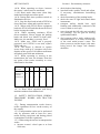
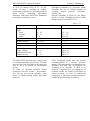
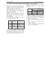
1.4.37. When operating or moving in the
transmission line area, the distance from the
top point of the tractor assembly to wires
should not be less than:
TL voltage,
up to kV
Horizontal
distance, m
Vertical
distance, m
11
2025
110
154220
330500
1.5
2
4
6
9
1
2
3
4
6
1.4. 38. Don’t allow operation with heavy
machines without front ballast load.
1.5. SAFETY REGULATIONS DURING
TRANSPORT WORKS AND TRACTOR
TOWING
1.5.1. During transportation works observe
traffic regulations in force on the territory of
the country.
1.5.2. Transportation works can be performed
only by operators with at least two years
tractor driving experience and having passed
examinations in traffic regulations.
1.5.3. When using the tractor in transportation
works:
increase tractor’s wheel span to at least
1900 mm;
check brakes functioning;
interlock brakes pedals, check and adjust,
if necessary, simultaneous functioning
thereof;
check functioning of the parking brake;
check the state of light and sound alarm
instruments;
transport trailers should have rigid
hitching and additionally connected with
reserve chain or steel rope;
never descend the hill with gear switched
off (coasting). Use one gear for moving
uphill and downhill;
don’t operate with a trailer without selfcontained brakes, if its mass exceeds half
of the total actual tractor’s mass. The
faster you move and the larger is the mass
being towed, the longer safe distance
should be.
MTZ 2022/2022V
1.5.5. Before starting the work, switch the
compressor on, check the state of the brakes
pneumatic drive, air pressure in the system.
Correct malfunctioning revealed.
1.5.6. Trailers ganged up to the tractor, should
be equipped with the braking system capable
of:
a) trailer braking while on the move;
b) brakes engagement when the trailer is
disconnected from the tractor;
c) trailer retaining when parked on slopes;
d) prevention of trailer’ s pushing action on
the tractor during sharp change in
movement speed.
The trailer should be connected to the
tractor by a reserve chain.
1.5.7. Transportation of people in trailers is
not allowed.
1.5.8. To avoid overturning, be careful when
driving the tractor. Select safe speed in
accordance with road condition, in particular,
when moving on the cross-country terrain,
crossing ditches, slopes and during sharp
turns.
1.5.9. Movement speed when making a turn
should not exceed 5 km/hour, on slippery
road – 3 km/hour. Put in 1st, or 2nd gear when
descending the hill. Movement speed on rail
road approach lines should not exceed 10
km/hour.
1.5.10. During trailer loading (unloading)
brake the tractor with the parking-reserve
brakes.
1.5.11. Tractor can be towed with nonoperational HTDS at the speed of 10 km/hour
maximum and to the distance of 5 km.
1.5.12. When used with a trailer on public
roads, the tractor should have road train
identification sign switched on according to
“Traffic regulations”.
1.6. SAFETY REGULATIONS DURING
MAINTENANCE
1.6.1. Maintenance should be carried out on
horizontal site, with diesel shut down and
wedges placed on both sides of rear wheels.
PTOS end must be braked, mounted machines
lowered and tractor braked.
1.6.2. To lift the tractor use the jack, and
when raised put supports under the front axle
beam, half-axles of rear wheels or basic parts
of the tractor frame.
1.6.3. Observe safety regulations when using
lifting-transport mechanisms.
Section 1. Safety regulations
1.6.4. To avoid fuel splashing during
mechanical tractor refueling, remove meshed
filter from the fuel tank neck. The meshed
filter is intended only for manual refueling in
field conditions.
1.6.5. To examine places to be controlled and
adjusted, use portable lamp with voltage not
more than 36 V. The lamp should be
protected by wire mesh.
MTZ 2022/2022V
Section 1. Precautionary measures
__________________________________________________________________________
1.6.6. The tools and appliances used for
maintenance should be serviceable, serve the
purpose and be safe in use.
1.6.7. Don’t inflate tires without gauging
pressure.
1.6.8. When servicing storage batteries:
a) avoid electrolyte dropping on skin;
b) wipe batteries with cloth soaked in
ammonium solution (salmiac);
c) when adjusting electrolyte level add only
distilled water;
d) do not check the battery charging by short
circuiting terminals;
e) do not connect the storage battery with
reverse polarity.
1.6.9. To avoid failure of electronic units in
the electrical equipment system observe the
following precautionary measures:
do not disconnect SB terminals with the
diesel in operation. This results in peak
voltage in the charge circuit and
inevitably causes diodes and transistors
failure.
Do not disconnect electrical wiring before
diesel stoppage and switching off all
electric switches;
Do not cause short circuiting arising due
to improperly connected wiring. Short
circuiting or wrong polarity lead to
damage of diodes and transistors;
Do not switch of the electrical equipment
system using the starter and instruments’
switch, as well as “ground” switch before
diesel completely stops;
Do not connect SB to the electrical
equipment
system
without
prior
examination of terminals' polarity and
voltage;
Do not check electric current “by
sparking”, as this will immediately lead to
transistors’ break down.
1.6.10. The cooling system operates under
pressure, sustained by the valve installed in
the surge tank cover. It’s dangerous to remove
cover on hot diesel. To avoid face and hands
burn, be careful when opening the tank neck
cover of the hot diesel. Put cloth on the plug
and use gloves.
1.6.11. To avoid danger of explosion, don’t
allow open flame source close to the diesel
fuel system and storage batteries
1.6.12. To avoid burns be careful when
draining coolant from the cooling system, hot
oil from diesel, hydraulic system and
transmission.
1.6.13. To assembly and dismantle the diesel
use steel rope fixing it to eye bolts provided
on the diesel.
1.6.14. Switch off SB when using electrical
welding during maintenance works.
1.6.15. Do not introduce any alterations in the
tractor design, or its components without
notifying the manufacturer. Otherwise, claims
under the warranty are not accepted.
1.6.15a The tractor shall not be operated
without SM as part of the electrical
equipment.
MTZ 2022/2022V
Section 1. Safety requirements
________________________________________________________________________________
1.7. FIRE SAFETY REGULATIONS
1.7.1. The tractor should be equipped with
fire-fighting implements – a spade and a fire
extinguisher.
1.7. 2. Never refuel the tractor with diesel
functioning.
1.7.3. Do not smoke when refueling the
tractor.
1.7.4. Do not fill in the fuel tanks to the full.
Leave some space for fuel expansion.
1.7.5. Never add benzene or mixtures to the
diesel fuel. These combinations may increase
danger of explosion and inflammation.
1.7.6. Tractors’ parting lot, fuel and lubricants
storage sites should be surrounded with at
least 3 m wide ploughed zone and provided
with fire-fighting implements.
1.7.7. Refuel the tractor mechanically with
diesel shut down. Use illumination at night.
The use of buckets for filling in fuel tanks is
not recommended.
1.7.8. Remove vegetation remains from
assembly units and parts when using electric
and gas welding during repair works under
field conditions.
1.7.9. Do not soil the muffler and collector
with dust, fuel, straw, etc.
1.7.10. Do not allow reeling of straw up the
rotating parts of machines ganged up to the
tractor.
1.7.11. When rinsing parts and assembly units
in kerosene or benzene, take measures to
exclude inflammation of rinsing fluids’
vapors.
1.7.12. Do not allow tractor’s operation in fire
dangerous areas with hood and other
protective items taken off heated diesel parts.
1.7.13. Do not use open flame to heat oil in
the oil pan, during filling in fuel tanks or
burning out soil in the radiator core.
1.7.14. When place of ignition arises, bury it
with sand, cover with tarpaulin or some other
dense material. Use carbon dioxide fire
extinguisher. Do not pour water on burning
fuel.
1.7.15. Check that during diesel operation
there were no inflammable materials close to
the exhaust collector and muffler.
1.7.16. When harvesting hay or straw, or
operating in fire highly dangerous areas, use
spark traps complete with muffler in the
exhaust system, or use them separately.
1.8.
SAFETY
STORAGE
REQUIREMENTS
IN
1.8.1. When putting the tractor for storage,
during maintenance in storage, or removing
from storage, observe relative requirements of
the present section and safety regulations
under GOST (state standard) 9.014-78.
MTZ 2022/2022V
1.8.2. During storage the tractor should be
placed on specially manufactured supports or
trestle to exclude its turning over or accidental
shifting.
1.9. HYGIENE REQUIREMENTS
1.9.1. First aid kit should be supplied with
bandages, iodine, salmiac, boric vaseline,
validole and analgine.
1.9.2.
Depending
on
environmental
conditions, use natural cabin ventilation, or
air conditioner/ heater.
Section 1. Precautionary measures
MTZ 2022/2022V
Section 2. General data.
2. GENERAL DATA
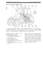
Farm high-power wheeled tractor MTZ 2022
of 3.0 class traction with 4 x 4 wheel
arrangement is designed for different
agricultural works using mounted, halfmounted,
trailing
machines,
loadingunloading
mechanisms,
harvesting
complexes, for driving stationary agricultural
machinery, including transportation in various
climatic zones.
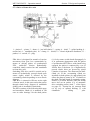
The tractor is equipped with an in-line sixcylinder diesel engine with turbo-charging
and intermediate cooling of supercharged air,
having rated power of 210 h/p with 2100
rev/min of the crankshaft.
Straight behind the diesel engine there are
power transmission mechanisms, the clutch,
gear box, rear axle with differential interlock,
rear power-take-off shaft with four-speed
independent drive (590; 720; 1105 and 1460
rev/min at 2100 rev/min of the diesel engine).
The clutch – two-disk, dry permanently
closed, with hydrostatic control drive.
Gear box – synchronized, fixed-ratio, rangetype, allows 24 front movement gears and 12
reverse movement gears.
The tractor chassis – drive rear wheels, drive
and guide front wheels. Front wheels’ tires
size – 420/70R24, rear wheels’ tires size –
580/70R42.
The front drive axle of MTZ: portal, with onepiece beam and planetary-cylindrical wheel
reduction gears.
Tractor’s steering – hydraulic, threedimensional, to ensure ease and simplicity of
tractor control in different applications.
Additional balance loads are installed on the
front beam to improve tractor’s coupling
characteristics and steering ability.
Hydraulic system of RLM control with threesection
distributor,
electro-magnetically
controlled governor, gauges, panels and
BOSCH electronic control unit provide tractor
operation with agricultural machines and
implements using power, position and mixed
control of implements position relative to the
tractor frame, and power take-off to drive
agricultural machinery tools. The tractor is
equipped with a pneumatic system that
controls hydraulically driven trailers’ brakes
and one-tube and two-tube pneumatic brakes
system.
Tractor’s brakes –hydraulically driven, wet,
multi-disk, installed on drive pinions of
vehicle-borne gears.
The cabin is solid, comfortable, airconditioned, it has cylindrical shape and upto-date exterior and interior design. To
improve operator’s working conditions the
tractor is provided with toned, spherical,
injury-safe glass, sun-proof curtains, enlarged
cabin space, more convenient location of side
panel levers, additional folding back seat,
additional rear window. Frameless door and
glued windscreen spherical glass provide
excellent all-round visibility.
Lining and wings are of modern design.
MTZ 2022/2022V
Section 2. General data
Two fuel tanks with total capacity of 357 l are
installed under the cabin floor on the right
side of the tractor.
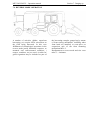
The diesel is shielded with a forward – swung
hood and removable sides. In the open
position the hood is fixed with a rod.
Optionally, the tractor can be supplied with
auxiliary equipment (RLM cross-bar,
additional seat, PTO-driven front mounted
mechanism, etc.).
Tractor MTZ 2022V is equipped with
reversible steering post intended for
prolonged operation in the reverse mode with
agricultural machinery mounted on the rear
hinge mechanism.
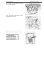
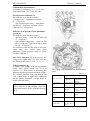
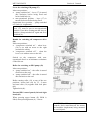
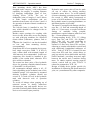
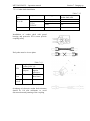
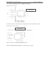
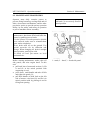
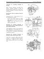
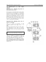
SERIES NUMBERS
COMPONENTS
OF
TRACTOR’S
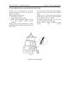
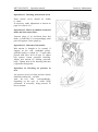
The company’s plate with series numbers of
the tractor and diesel is attached in the cabin
right-side niche on the tractor rear.
MTZ 2022/2022V
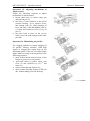
Series number of the tractor is duplicated on
the right-side frame girder, and right-side
plate of the front ballast.
Series diesel number is duplicated on the
company’s plate fixed to the cylinder block
(on the left side).
Series number of the diesel turbo-compressor.
Clutch series number.
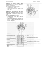
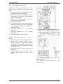
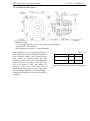
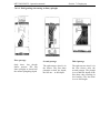
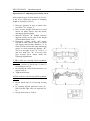
Section 2. General data
MTZ 2022/2022V
Series chassis number is punched on the right
side of the rear axle body
Series FDA number is punched on the FDA
body in frond of the tractor.
The cabin series number and number of the
OECD certificate. The plate is fixed in the
cabin right-side niche under company’s plate.
Section 2. General data
MTZ 2022/2022V
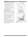
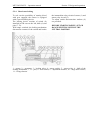
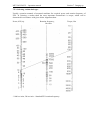
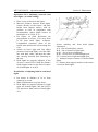
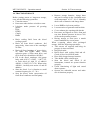
Section 3. Technical data
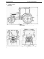
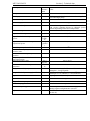
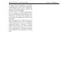
3. TECHNICAL DATA
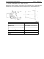
Dimensions
Left-side view
Front view
Rear view
MTZ 2022/2022V
Section 3. Technical data
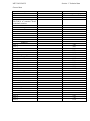
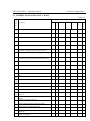
General data
Description
Type of tractor
Tractor make
Tractor model
Rated travel speed using tires
580/70R38 at nominal diesel
crankshaft rotation:
Forward motion
Range 1
Gear 1
Gear 2
Gear 3
Gear 4
Gear 5
Gear 6
Range II
Gear 1
Gear 2
Gear 3
Gear 4
Gear 5
Gear 6
Range III
Gear 1
Gear 2
Gear 3
Gear 4
Gear 5
Gear 6
Range IV
Gear 1
Gear2
Gear 3
Gear 4
Gear 5
Gear 6
Rear motion
Range I
Gear 1
Gear 2
Gear 3
Gear 4
Gear 5
Gear 6
Unit of measurement
Km/hour
Value
Agricultural, general purpose
MTZ
2022; 2022V
1.79
2.38
3.10
3.99
5.13
6.65
3.46
4.60
5.99
7.71
9.90
12.85
5.35
7.10
9.24
11.90
15.29
19.83
10.33
13.72
17.85
22.98
29.53
38.30
2.51
3.34
4.35
5.60
7.20
9.34
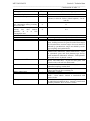
MTZ 2022/2022V
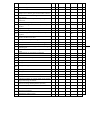
Description
Unit of
measurement
Section 3. Technical data
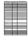
Continuation of table 3.1
Value
Range II
Gear 1
Gear 2
Gear 3
Gear 4
Gear 5
Gear 6
Nominal traction force
Km/h
4.86
6.46
8.40
kN ( kgs)
10.82
13.90
18.03
30 (3000)
* length in travel condition (with
loads), rear hinge system including
* width, at ends of rear wheels halfaxles
* height, cabin top
mm
5230 +/- 50
mm
2500 +/- 20
mm
3090 +/- 30
Tractor wheelbase
mm
2920 +/- 50
Tractor wheelspan
mm
* front wheels (stepwise)
mm
1640-2190
* rear wheels (stepless-stepwise)
mm
1800-2500
degrees
35
mm
430 (550 for tires 580/70R42)
m
5.3
kg
6830 +/- 100 ( 6900 +/- 100 - 2022V)
Tractor dimensions (nominal)
Angle of rolling static stability,
minimum
Ground clearance ( with standard
tires)
under rear axle body
Minimum turning radius from the
center of the track of the outside
front wheel with 1800 mm
wheelspan and braked inside rear
wheel
Tractor mass ( as dispatched from
the manufacturer)
Allowable load on axles (not
accounting for tires carrying
capacity):
* front axle
* rear axle
Braking distance at the speed of 30
km/h with cold brakes, maximum
Depth of ford being crossed
Full mass of towed trailer ( brakes
of the tractor and trailer
interlocked)
DIESEL
Type
Number of cylinders
Firing order
Cylinder diameter
Piston stroke
Displacement volume
kN
m
50
75
13
m
0.85
kg
25000
pieces
-
D-260.4 or D-260.4C2
6
1-5-3-6-2-4
mm
mm
L ( cm)3
110
125
7.12 (7120)
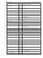
MTZ 2022/2022V
Section 3. Technical data
Continuation of table 3.1
Description
Unit of
measure Value
ment
-
Compression ratio
15.0
Cooling system
-
Lubrication system
-
Fluid-type with forced circulation of cooling fluid
from centrifugal pump
Combined
Oil cooling system
-
In-built fluid-oil heat exchanger
Thermal mode adjustment
-
Rated diesel power
hp (kW)
Automatic, using two thermostats and a ventilator
with viscous coupling driven by thermal- power
element depending on the diesel temperature
210 (154)
Operational diesel power
hp (kW)
200 (147)
Specific fuel consumption at rated
power
g/h.p.h
(g/kW.
h)
G/h.p.h
(g/kW.h
)
Rev/min
162 (220)
2100 + 40 -25
Rev/min
2275
Rev/min
800
Rev/min
1400
N.m (
kgs.m)
807.5 (82.3)
Specific
fuel
operational power
consumption
at
Rated frequency of crankshaft rotation
Maximum frequency of idle run
rotation, max.
Maximum stable frequency of idle run
rotation
Frequency of crankshaft rotation at
maximum torque
Maximum torque value
Correct coefficient of torque allowance,
minimum
High pressure fuel pump
170 (230)
15 +10 / -3
%
-
type
-
363.1111005-40.04 (YAZDA) or PP6M10P1f-3493
“Motoplan”, Czeck Republic
YAZDA: 19-21 0 (D-260.4); 16-18 O (D-260.4C);
“Motorpal” 21-23 (D260.4); 17-19 (D-260.4C)
6- plunger, in-line (“Motorpal”, YAZDA)
Direction of camshaft rotation
-
Right-side
Type of booster pump
-
Hand mump type
-
piston
Rotation frequency governor
-
injector
-
Variable-speed with automatic fuel supply dresser at
starting regimes and pneumatic corrector
17/171.1112010-01 (D-260.4); 17/171/1112010-0101
(D-260.4C)
Angle of lead of power supply to TDC
degrees
Piston, eccentric driven
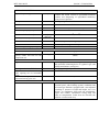
MTZ 2022/2022V
Section3. Technical data
________________________________________________________________________________
Continuation of table 3.1
Air purifier “Donaldson” - with dry three-step purification, with built-in mono separator
Starting system
Mass of the dry diesel
Make of turbo-compressor
Relative oil consumption, in % to
fuel consumption during warranty
service life, max.
Relative oil consumption for
burning
loss
after
60-hors
operation,
in
%
to
fuel
consumption, max.
POWER TRANSMISSION
Clutch
Clutch control drive
Gear box
-
Electric starter with pre-start heating plug
kg
700 +/- 3%
-
TKP-7 or S2A; “Shwitzer” K27 (TBP4 “Garret”
(France) or G22-02 “Turbo” (Check republic) – for D260.4C)
%
1.1
%
0.4
-
Friction-type, dry, constantly closed, two-disk
Hydrostatic
24F + 12R; mechanical, stepwise, with constant mesh
gears, shifting between six gears in each of four ranges
in forward motion, and two ranges of reverse motion is
effected by synchronizers, ranges are shifted by toothtype couplings and synchronizers.
Supplied with final drive- a pair of cone gears with
circular teeth; differential; vehicle-borne drives – a pair
of cylindrical gears and final planetary-type drives;
with mechanical differential interlock with hydraulic
drive and electric- hydraulic control.
Portal, beam-type with planetary-cylindrical final
drives. The final drive -–a pare of cone gears with
circular teeth, with self-lock differential.
From GB via friction electrically-hydraulically
controlled coupling, cardan shaft
Electrical-hydraulic distributor provides automatic
control and forced drive switching on.
Hydrostatic, isolated
Wet, multi-disk, effect rear, and via FDA drive disk
brake – front wheels. Control is interlocked with
trailer’s brake.
Multi-disk, wet, integrated with working brakes, with
an individual mechanical drive. Control is interlocked
with the pneumatic drive of trailer’s brakes.
Rear axle
-
Front drive axle MTZ
-
FDA drive
-
FDA control
-
Brakes control drive
Brakes
-
Parking-reserve brake
-
MTZ 2022/2022V
The drive for trailers’ brakes
control
Pneumatic system pressure limited
by safety valve
Controller-sustained pressure
Mpa
(kgs/c
m2)
Mpa
(kgs/c
m2)
Section 3. Technical data
Continuation of table 3.1
Pneumatic one-pipe ( optionally – two-pipe), interlocked
with tractor’s brakes control
0.85…1.00
(8.5…10)
0.65…0.80
(6.5…8.0)
REAR PTO
Drive
-
Four-speed, independent
End rotation frequency
* independent drive (standard)
Rev/m 540 at 1924 rev/min of the diesel to transmit power not
in
more than 60 kW; 1000 at 1909 rev/min of the diesel to
transmit full power
* independent (economical) drive
Rev/m 540 at 1603 and 1000 at 1615 rev/min of the diesel
in
Size of the end and rotation
Ends of type 1; 1C*; 2; 3 ( clockwise, if one looks at the
direction
end face)
FRAME, CHASSIS
Tractor’ frame
-
Half-frame
Frame suspension
-
Stiff
Chassis
-
Front and rear drive wheels with pneumatic tires
Guide front wheels
Rear wheels can be doubled using an attachment
Tires :
front wheels
4220/70R24; 480/65R24
rear wheels
580/70R42;580/70R38; 650/65R42
STEERING
Type
-
Hydraulic, three-dimensional
Type of supply pump
-
Gear
Displacement volume
cm3/re
v
Mpa
(kgs/c
m2)
-
14-16
Rated pressure made by supply
pump
Rotation direction
Type of metering pump
-
Displacement volume
Pressure of safety valve adjustment
Pressure of shock proof
adjustment
valves
Type of turning mechanism
Force of steering wheel turn with
operational supply pump
Steering wheel play
*) Available in spare parts kit
cm3/re
v
Mpa
(kgs/c
m2)
Mpa (
kgs/c
m2)
N
degrees
16
(160)
Left-side
Gerotory
160
14+ 1.5
(140 + 15)
20 +2
(200 + 20)
Two-rod hydraulic cylinder or two hydraulic cylinders
50 x 250 mm in diameter
30
25
MTZ 2022/2022V
Section 3. Technical data
Continuation of table 3.1
HYDRAULIC SYSTEM
Hydraulic system type
Pump
-
Remote-cylinder hydraulic system allowing for power,
position and mixed control of agricultural machines
position and dampening of agricultural machinery
swing in travel position
Gear-type, right-hand rotation
Model
-
NSH32M-3
Drive
-
-
Maximum pump capacity
Pressure of safe valve adjustment
Hitch cylinders (2 pieces)
Distributor
l/min
56
Mpa
(kgs/cm2)
Mm
20 -2.0 (200 –20)
-
Controller
Electric magnets supply voltage
V
REAR HITCH
Hitch mechanism
Load- lifting capacity, with load
kN (kgs)
gravity center 610 mm off the
suspension axis
TRACTION-COUPLING MECHANISM
Type
-
Towing mechanism (TSU-38)
*distance from PTO face to towing
yoke opening axis in horizontal
plane
* distance from ground surface to
horizontal towing yoke axis
CABIN
See section 2 “General data”
From diesel via the pinion of PTO independent drive
TS 90 x 250
3-section, 4-position, flow type by BOSCH
Electric-hydraulic, type EHR4 by BOSCH
12
Articulated, four-link, category 3
46
(4600)
-
General-purpose; includes towing mechanism (yoke),
and (optional) connecting device of “python” type, and
trailing mechanism ( towing bar)
Lifting-type, height adjusted
400 +/- 10
mm
400-850 ( in 65 mm)
-
One-seat, with safe rigid frame, thermal-noisevibration proof, with a heating system, ventilation and
air heater-type filtration, equipped with a seat adjusted
according to operator’s weight and height, rear view
mirrors, air conditioner, front and rear windshields’
wipers and washers, illumination ceiling lamp and
radio set compartment. Cabin doors are lockable, the
left door is locked with a key
MTZ 2022/2022V
Section 3. Technical data
Continuation of table 3.1
Reversible steering post (2022V)
* steering column
Additional, with a metering pump
* fuel supply control
Duplicated, steel rope
* clutch and brakes control
Duplicated pedal drives for clutch and brakes control
* seat
Main seat, reversed by 180 0 by reversing mechanism
ELECTRICAL EQUIPMENT AND INSTRUMENTATION
Rated voltage:
* tractor-system voltage
V
12
* starting system
V
24
Supply system
Storage batteries ( 2 pcs.) 12 V, capacity 120 A.h each,
connected in parallel, starting discharge at –18 0C –
500A, 12V generator, 2000W power, alternated current
with built-in rectifier and voltage regulator
Illumination and light alarm
- front road illumination head lights (high beam,
system
lower beam) – 4 pieces;
- front (2 pcs.) and rear (4 pcs.) operation headlights,
containing side lights and tractor turning alarm
lights;
- rear lamps ( 2 pieces) containing side lights,
turning alarm lights and brake alarm lights;
cateyes;
- license plate illumination lamp;
- cabin ceiling light;
- emergency alarm lights
Sound alarm system
A set of two horn tone signals and one horn-less signal
Emergency sound alarm system
Buzzer ( upon diesel oil pressure drop or rise of
cooling liquid temperature above rated value
MTZ 2022/2022V
Section 3. Technical data
Continuation of table 3.1
Tachometer-speedometer
Electrical ( complete with programming panel)
Control lamps
Signaling system of high beam; tractor and trailers’
turns, parking brake, air filter clogging, HTDS oil
pressure; engagement of differential and FDA
interlocking; braking fluid pressure in brake master
cylinders; diesel starting up, means of easing diesel
start up.
BALLAST LOADS
Mass of one load
kg
45 +/- 1.5
Total mass
kg
510 +20 + additionally 420
-
MM-2
kg
250
-
SA-1
* distance from PTO end face to hitching point
mm
675
* vertical movement of hitching point
mm
200-980 (stepless)
* diameter of connecting opening
mm
32
* horizontal movement of hitching point
mm
400 (on both sides space 8 )
* vertical static load
kgs
600
mm
400; 500
mm
465
* with 400 mm overhang from PTO end face
kgs
2000
* with 500 mm overhang from PTO end face
kgs
1500
pieces
2
-
For a passenger
-
Independent, one-speed
rev/min
1000
-
Clockwise (when looking at the end)
-
PTO 2; 21 slots
AUXILLIARY WORK EQUIPMENT ( optional)
Front mounting mechanism (MM)
* load-lifting capacity of lower tie-rod axis
Automatic front MM coupling
Crossbar of the rear hinging mechanism
Hitching device ( towing bar):
* distance from PTO end face to hitching point
in horizontal plane
* distance from ground surface to hitching point
* allowable vertical load:
Support for rear wheels doubling
Additional seat
Front PTO:
* drive
* rotation frequency of the PTO end with 1845
rev/min rotation frequency of the diesel
crankshaft
* direction of the end movement
* end size
MTZ 2022/2022V
Transmitted power, maximum
Section 3. Technical data
Continuation of table 3.1
60
(44)
Non-adjustable
Towing- hitching device TSU-2P “Python”
h.p.
(kW)
-
Outside diameter of the connecting rod
mm
44.6
*distance from PTO end face to the center
mm
110
* allowable vertical load
kgs
3000
* distance from ground surface to hitching
point
mm
530
MTZ 2022/2022V
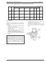
Section 4. Controls
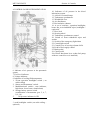
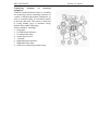
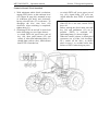
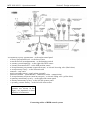
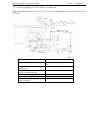
4 CONTROLS AND INSTRUMENTATION
10. Indicator of oil pressure in the diesel
lubrication system
11. A block of control lamps
12. Tachometer-speedometer
13. Windshield visor
14. Air distributors
15. Recirculation shutters
16. A set of switches ( operation headlights,
heater fan, rear windshield wiper, headlights “
road train”
17. Door lock
18. Steering wheel
19. Tachometer-speedometer control
20. Switch of front windshield wiper and
washer
21. Switch of the emergency light alarm
22. Central light switch
23. Control lever of steering column tilt fix
24. Pedal of fuel supply control
25. Brake pedal
26. Clutch pedal
26a. Diesel shut down lever (when fuel pump
with two control levers is installed)
6. Indicator of air pressure in the pneumatic
system
7. Fuel level indicator
8. Voltage indicator;
9. Indicator of cooling fluid temperature
1. *Front operation headlights switch ( on
cabin railing)
2. Starter and instruments’ switch
3. Multifunctional switch ( turn indicator,
high beam, lower beam, sound alarm)
4. Storage battery remote switch
(combination of instruments (pos. 5, 6, 7,
8, 9, 10)
5
Oil pressure indicator in GB
*) road headlights switch (on cabin railing –
optional)
MTZ 2022/2022V
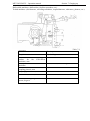
Section 4. Controls
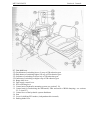
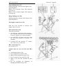
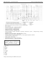
27. Gear shift lever
27a. Push button of switching lower (L) step of GB reduction gear
27b.Push button of switching higher (H) step of GB reduction gear
27c. Indicator of switching on lower step of GB reduction gear
27d. Indicator of switching on higher step of GB reduction gear
28. Range shift lever
29. Fuel supply control lever
30. PTO switching lever
31. Control unit of hydraulic mounting system (see section 5.12)
32. Control unit for interlocking the differential, FDA and mode of RLM damping ( see sections
5.3; 5.4 and 5.7)
33. Control lever of the hydraulic system distributor
34. Seat
35. Lever for shifting PTO modes ( independent drive/neutral)
36. Parking brake lever
MTZ 2022/2022V
Section 4.Controls
Starter and controls switch (2)
It has four positions:
0 – switched on
I – instruments, control lamps, a radio set, a
tape recorder are switched on
II - sparking plugs are switched on (position
is not fixed) with this, in the block of control
lamps ( with diesel cold) start up control lamp
lights, and in the oil pressure indicator -–a
control lamp of emergency pressure lights and
sound signal sounds (buzzer);
III – starter is switched on (position is not
fixed), after diesel start up control lamp goes
down and sound alarm switches off
MULTIFUNCTIONAL (UNDER STEERING
WHEEL) SWITCH (3)
It allows to switch turn lights, change front
headlights’ high/lower beam, high beam
signal, sound alarm.
PUSHBUTTON (4) OF REMOTE SB
SWITCH
When pushing the button, batteries are
activated, repeated pushing switches them off.
TURN INDICATORS are switched by moving
lever from the middle position forward or
back. After tractor’s turn the lever is
automatically reset.
SOUND ALARM is activated by pressing the
lever in axial direction. Signal is switched on
in any position of the switch.
CHANGING HIGH/LOWER BEAM OF
HEADLIGHTS ( after pushing button (22) in
position <3>, page 36, is effected by moving
lever up/down along the steering column axis:
high beam – lower fixed position; lower beam
– middle fixed position; high beam blinking –
by moving upwards to the end from the
middle position ( non-fixed position).
SWITCH* OF FRONT OPERATION
HEADLIGHTS (1).
When pressing switch key (1), front operation
headlights, installed on cabin handrail are
switched on. Simultaneously light key
indicator is on.
_____________________________________
*) The switch of road illumination headlights
installed on cabin handrail is optional.
MTZ 2022/2022V
Section 4. Controls
Combination of instruments
It includes six indicators ( 5, 6, 7, 8, 9, 10 )
with signal lamps ( 6a, 7a, 8a, 9a, 10a)
GB oil pressure indicator (5)
The indicator scale has three zones:
- operation zone – from 800 to 800 kPa
(8…15 kgs/cm2);
- non-operation zone (two) – from 400 to
800 kPa (4…8 kgs/cm2) and from 1500 to
1800 kPa (15…18 kgs/cm2).
Indicator of air pressure in the pneumatic
system (6)
The indicator scale has three zones:
- operation zone – from 500 to 800 kPa
(5…8 kgs/cm 2);
- non-operation zones (two) – from 0 to 500
kPa (0-5 kgs/cm 2) and from 800 to 1000
kPa (8…10 kgs/cm 2).
The indicator scale has the built-in red color
signal lamp (6a), which lights when
pneumatic system pressure drops to below
500 kPa (5 kgs/cm 2).
Fuel level indicator (7) with reserve fuel
orange color signal lamp (7a). The scale has
the following divisions < 0-1/4 – ½, ¾, -1>.
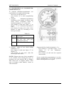
Voltage indicator (8)
It displays SB voltage with non-operational
diesel, when starter switch key (2) is in
position <I>. With diesel in operation, the
indicator displays generator terminals voltage.
The voltage indicator scale has built-in red
color control lamp. It lights when additional
storage battery terminals’ voltage drops to
below allowable limit.
IMPORTANT! If voltage indicator (8)
shows absence of SB charging, check the
state and tension of the generator driving
belt.
The voltage indicator scale has the following
zones:
Table 4-1
Supply system state
Scale zone, color
With diesel in
operation
10.0 –12.o V
red
SB is charged
12.0-13.2 V
yellow
SB is normally
charged
With
nonoperational
diesel
Generator
doesn’t function
No SB charge
(low
charging
voltage)
13.2 – 15.2 V
Green
Normal charging
mode
15.2 – 16.0 V
red
SB recharging
White mark in the
yellow zone
Normal, EMF
of the SB is
12.7V
MTZ 2022/2022V
Section 4. Controls
________________________________________________________________________________
Indicator
of
diesel
cooling
fluid
temperature (9) with excessive temperature
indicator (9a) (red color)
The instrument scale has three zones:
- operation zone – 80-100 °C;
- non-operation zones (two) – 40-80 °C and
100…120 °C
Indicator of oil pressure in the diesel
lubrication system (10) with a red color
control lamp of emergency pressure drop
(10a)
The indicator scale has three zones:
- operation zone – from 100 to 500 kPa
(1…5 kgz/cm2)
- non-operation zones (two) – from 0 to 100
kPa (0…1 kgs/cm2) and from 500 to 600
kPa (5…6 kgs/cm2)
A set of control lamps (11)
Control lamp of tractor turn
(green color)
Control lamp of trailer turn
(green color)
Control lamp of parking brake
(red color)
Control lamp of oil pressure
critical drop in HTDS system
(red color)
Control lamp of maximum
clogging of air purification
filter (orange color)
Control lamp of high beam (blue
color)
Control lamp of interlocking rear axle
differential (orange color)
Control lamp of sparking plugs (orange color)
Control lamp of diesel start up (red color)
Control lamp of braking fluid level (red color)
MTZ 2022/2022V
Section 4. Controls
Tachometer-speedometer (12)
Electrical tachometer-speedometer installed
on the instrument panels operates as follows:
When tractor stops and after starter and
instruments switch is put in position < I
>, the display (7) indicates (5) total diesel
operating time in hours;
Upon diesel start up the pointer indicator
(8) moves along the circular scale (1) to
indicate frequency of diesel crankshaft
rotation. Meantime, display (4) shows
PTO rotation frequency (rev/min). Scale
(3) – for PTO I, and scale (2) – for PTO
II. Electric signal of rotation frequency is
sent from the generator phase winding;
During tractor travel display (7) indicates
movement speed (km/h), while indication
(5) disappears. The electric signal of
movement speed is sent from speed
sensors installed on the rear axle cover.
Tachometer-speedometer
panel (19)
(12)
control
The control panel is installed on the
instruments’ board and is used for
programming
tachometer-speedometer
according to tractor MTZ models, radius of
rear wheels swing and diesel models.
1. Scale of diesel crankshaft rotation frequency,
rev/min.
2. Scale of PTO II rotation frequency –1000
rev/min.
3. Scale of PTO I rotation frequency – 540
rev/min.
4. Display of PTO rotation frequency.
5. Indication of diesel operating time, hours.
6. Indication of tractor movement speed, km/h.
7. Display of diesel operating time and tractor
movement speed.
8. Pointer indicator of diesel crankshaft rotation
frequency.
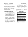
Parameter Value
NOTICE! Tachometer-speedometer has
been programmed exactly for your tractor
model at the manufacturer. Reprogramming will be required only upon
changing of tires type. Do not re-program
the tachometer-speedometer, if not
required.
1. Pushbutton for entering parametric code
on the tachometer-speedometer display
(7).
2. Pushbutton for entering to the tachometerspeedometer display (7) of coded
numbers’ values when programming
according to tractor models, radius of rear
wheels swing and diesel models.
MTZ 2022/2022V
A set of switches (16), ( fan, heater, operation
headlights, front and rear,
rear windshield wiper, road train headlights).
Switch of cabin heater fan has three
positions:
1. Switched on:
2. The 1st operation mode is switched on
(small air supply).
3. The 2nd operation mode is switched on
(large air supply).
Switches of front operation headlights
When pushing the key front operation
headlights and key light indicator are on.
Switches of rear operation headlights
When pushing the keys rear operation
headlights and keys’ light indicators are on.
Switch of rear windshield wiper has three
positions:
1. Switched off
2. Windshield wiper is switched on
3. Windshield wiper and washer (not fixed)
are switched on.
Switch of “road train” sign lights
When pushing the key road train signal lamps
and key light indicator are switched on.
Section 4. Controls
MTZ 2022/2022V
Fuses
Fuse box is installed under cover “A”.
Five fuses protect from overload the following
electric circuits:
1. Cabin ceiling light and “road train” sign (7.5
A)
2. Rear windshield wiper and washer (7.5A)
3. Two pairs of front operation headlights (25
4. Two pairs of rear operation headlights (25 A)
5. Cabin ventilation and heating system (15 A)
6. Reserve (15 A)
Cabin door lock (17)
Handle (A) is designed for opening the cabin
door: pull the handle back to open the door . Push
handle (B) back to interlock the door from
possible opening from outside.
Multifunctional switch, the right-hand (20)
provides:
switching on two-speed electric front
windshield wiper;
switching on front windshield washer.
To switch on the windshield wiper shift the
switch handle from position “switched off” (the
end front position “0”) to position “I” back (1st
speed), or “II” (2nd speed). All positions are fixed.
To switch on the windshield washer (not fixed)
shift the handle up from any of the three switch
positions.
Section 4. Controls
MTZ 2022/2022V
Section
Switch of light emergency alarm (21)
Press button (21) to switch on light
emergency alarm. The control lamp built-n
the button is blinking as light alarm blinks.
:
Central light switch (22)
It has three positions:
1. Switched off. The right button part is
pressed.
2. Front and rear side lights are switched on,
instruments illumination, license plate
illumination, trailing machine side lights,
auxiliary trailing machine headlights,
information display and processing panel.
Middle position.
3. All systems from position “2” and front
road headlights are switched on.
Left button side is pressed.
OFF
4.
Controls
MTZ 2022/2022V
Section 4. Controls
Fuse boxes
Two electric circuits’ fuse boxes BP-1 and
BP-2 are installed under the instruments
panel.
To get access to fuses unscrew screw (A) and
remove cover (B).
Eleven fuses protect the following electric
circuits from overload:
FB – 1
1. Instruments’ power supply (7.5 A);
2. Interrupter of turn indicators (7.5 A);
3. Lower light of the right-hand road
headlight (7.5 A);
4. Lower light of the left-hand road
headlight (7.5 A );
5. Right-hand side lights and instruments
panel illumination (15 A);
6. Left-hand side lights (7.5 );
FB-2
1.
2.
3.
4.
5.
High light of road headlights (15 A);
Sound signal (15 A);
Sparking plugs of the pre-start heating;
Emergency light alarm(15 A);
Front windshield wiper and washer (15
A);
6. Stop light (15 A);
Safety system unit for control of FDA, DL,
RLM and GB reduction gear
Fuses (7.5 A) protect the following circuits:
1. Front drive axle;
2. Rear axle DL;
3. Reserve;
4. Suppression of RLM damping;
5. Control of GB reduction gear;
6. Reserve.
CAUTION! To avoid tractor wiring
burning, never use fuses with strength of
current over the rated values given below. If
a fuse blows too often, find out the reason
and correct it.
MTZ 2022/2022V
Connecting
elements
of
electrical
equipment
Combined multifunctional socket is intended
for connecting current consuming elements of
a trailer or hitched agricultural implement, as
well as a portable lamp. It is mounted outside
to the rear cabin wall. The socket is connected
to wiring bundle plug of machines being
hitched and portable lamp plug.
Socket terminals’ markings:
1. Stop light;
2. Left-hand turn indicator;
3. Left-hand side lamp;
4. Sound alarm device;
5. “Ground”;
6. Right-hand turn indicator;
7. Right-hand side lamp;
8. Socket for connecting portable lamp.
Section 4. Controls
MTZ 2022/2022V
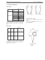
Gears shifting lever (27)
Shifting diagram is shown in the figure to the
right (diagram I)
Button (27a) switches lower GB reduction
gear step (L).
Button (27b) switches higher GB reduction
gear step (H).
Range shifting lever (28)
Shifting diagram is shown in the figure to the
right (diagram II).
Fuel supply control lever (29)
Push the lever forward to increase fuel
supply, and visa versa.
PTO control lever (30)
It has three positions:
smooth lever movement from position <
N > (neutral) down to the end switches
PTO on ( position “Ф” (friction clutch);
to switch PTO off, move the lever from
the end front position to position “N”
(neutral);
to brake PTO end (position “T” (brake),
move the lever up to the end.
HLS control unit (31)
(see section 5.12)
Control unit for rear axle DL and FDA
(32)
sound alarm button (32a);
key for FDA drive control (32b);
light of FDA switched on state (32c);
key for control of rear axle DL (32d);
light of rear axle DL switched on state
(32e);
key for switching on “damping” of
hinging mechanism swing (32f).
Section 4. Controls
MTZ 2022/2022V
Section 4. Controls
Levers for control of hydraulic system
distributor (33a, 33b, 33c)
Control levers are located on the cabin righthand side panel. They have the following
positions: “neutral”, “lowering”, “floating”,
and “lifting”.
Lever (33a) controls left-hand tractor
distributor section along the motion direction,
and left-hand rear outlets of the hydraulic
system.
It is fixed in positions “floating” and
“neutral”. Lever (33b) controls the middle
distributor section and middle rear outlets of
the hydraulic system. It is fixed in “floating”
and “neutral” positions.
Lever (33b) controls right-hand distributor’s
section and right-hand real outlets of the
hydraulic system. It is fixed in all positions.
Seat (34)
It can be adjusted according to:
Weight of an operator. To adjust for
greater weight, rotate the lever clockwise,
and visa versa.
Longitudinal adjustment. Move the lever
upwards to the end and move the seat
forward or backwards.
Back tilt. Move the back tilt adjustment
lever upwards to the end, then lower and
fix the back in the required position.
Height adjustment. Move the seat
upwards by hands (to increase the seat
height). To decrease the seat height,
sharply jerk the seat up to the end and
then lower it by pushing downwards (after
pushing the seat drops to the lowest
position all by itself).
-
adjustment of back tilt angle
-
place for safety belt attachment
-
longitudinal adjustment
-
operator’s weight adjustment
MTZ 2022/2022V
Handle (35) for switching on the
independent PTO drive
The handle (35) has two positions:
“Independent PTO drive is switched on” the end lower position;
“Switched off” (neutral) – the end top
position.
Parking brake control lever (36)
“Parking brake engaged” - top end
position,
“Parking brake disengaged” - end low
position.
Switch for changing velocity of PTO
independent drive (35a)
The independent drive switching lever (35a)
has two positions:
I – 590 and 1105 rev/min – the end, anti
clockwise;
II - 720 and 1460 rev/min – the end,
clockwise.
To set the required velocity of PTO rotation,
loosen bolt (1), turn the lever and tighten the
bolt.
Steering wheel (18)
1. Position of the steering wheel can be
adjusted by height within 100 mm.
To make adjustment do the following:
take the cover off (2);
unscrew fastener (1) by 3…5 turns;
move steering wheel (18) back or forward,
choosing the position most comfortable
for operation;
screw the fastener up and put the cover in
place.
2. Tilt of the steering column can be changed
stepwise in the range of 25°– 40°with 5° space.
To change the steering column tilt pull back
handle (23) (see page 29), tilt the column and
steering wheel to the required position,
release the lever and slightly lower the
column to the fixed position.
Section 4. Controls
MTZ 2022/2022V
Section 4. Controls
Lever for switching GB pump (37)
It has two positions:
“pump switched on” - lever (37) is turned
anti clockwise before being fixed and
locked with bolt (A);
non-operational position – lever (37) is
turned clockwise before being fixed.
Operational lever position – “pump switched
on” (bolt (A) is tightened).
NOTE. If cover (B) needs to be dismantled,
lever (37) must be put to non-operational
position. Upon drive setting turn the lever to
position “pump switched on” again and fix it
with bolt (A).
Handle for switching off compressor drive
(38)
It has two positions:
“compressor switched on” - when lever
(38) is set with an arrow to the right
(towards the cabin);
“compressor switched off” - when the
lever is set with an arrow to the left.
OFF
ON
Switch on the compressor with nonoperational diesel or at minimum revolutions
of the idle run.
Roller for switching on HLS pump (39)
It has two positions:
“pump switched on” - the roller is turned
clockwise to the end;
“pump switched off” - the roller is turned
anti clockwise to the end.
Before turning roller (39) to any of the two
positions, loosen bolt (41) by 1.5…2 turns
and turn roller (39) together with lock plate
(40)
Tighten bolt (41).
External HLS control panels (left and right
hand) (42)
When pressing upper button (P), RLM is
lifted, when pressing button (0) – lowers.
CAUTION! When using external
controls, don’t stand between the tractor
and machine (implement) being mounted
to avoid injures.
MTZ 2022/2022V
4.1. REVERSIBLE CONTROL
(MTZ 2022V)
Section 4. Controls
POST
To improve possibilities of ganging up
tractors to front mounted agricultural
machines they are equipped with a reversible
control post.
Elements of reverse control:
auxiliary steering column with a meter
pump;
duplicated pedal drives for control of
friction clutch, brakes, fuel supply;
seat reversing mechanism;
auxiliary sound alarm button and light of
emergency modes of diesel operation.
NOTICE!
1. Tractor’s reversible control post is
designed only for agricultural
operations when moving in reverse
direction.
2. Be sure to interlock forward motion
brake pedals when working in the
reverse order.
3. Do not drive in reverse on public
roads, in operations not related
agriculture, or loading/unloading
the tractor itself.
MTZ 2022/2022V
Section 4. Controls
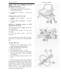
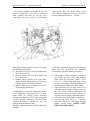
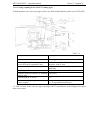
4.1.1 Reversible post controls
Additional controls are placed in the rear
cabin section, as shown in the figure to the
right.
1. Clutch pedal. Press the pedal to disengage
the clutch, release it to engage it.
2. Brakes pedal. Press the pedal to engage
both brakes of the tractor and pneumatic
drive of trailer brakes.
3. Pedal of fuel supply control. Press the
pedal to increase fuel supply.
4. Sound alarm button.
5. Lever of fuel supply control. The end rear
position (on the reverse post) corresponds
to maximum fuel supply, the middle end –
diesel shut down.
6. GB range shifting lever. ( see shifting
diagram II)
7. GB gear shifting lever (see shifting
diagram II).
8. Forward motion steering column.
Do the following operations to work in
reverse:
interlock forward motion braking pedals;
reinstall the steering wheel on the
auxiliary column. To this end, unscrew
the hand wheel fixing the steering wheel,
reinstall the steering wheel and fix it at the
required height.
Install the reversible seat for operation in
the reverse.
Fulfill operations from Section 5.2 to
transfer clutch control in the reverse
mode.
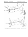
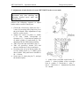
1- clutch pedal; 2- steering wheel; 3- brakes
pedal; 4- fuel supply control pedal; 5sound alarm button; 6 – fuel supply lever;
7- GB range shifting lever; 8 – gear
shifting lever; 9 – forward motion steering
wheel.
“L” – button of switching lower step of GB
reduction gear;
“H” – button of switching higher step of GB
reduction gear.
MTZ 2022/2022V
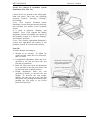
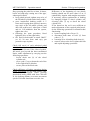
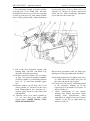
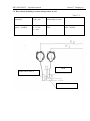
Observe the following sequence of operations
to adjust the seat for the work in reverse:
Lower clamps (1) and push them aside to
release cheek-pieces (3) of the upper
lifting mechanism frame;
Applying effort upwards and downwards,
bring the seat to the utmost position;
Pull handle (4) to release turning
mechanism and turn the seat by 180°;
Insert clamps in-between cheek-pieces
and tighten them to the end.
Follow reverse order to put the seat in the
forward motion position.
Seat adjustments are independent and can be
performed while on the move.
Use handle (7) to make adjustments according
to operator’s weight. By turning the handle
clockwise, the seat is set for larger weight,
while turning it anti clockwise – for smaller
one.
Longitudinal adjustment is effected by lever
(6), which should be pushed to the end right
side to shift the seat forward or back.
To increase the seat height pull it manually
upwards in a stepwise manner.
To reduce the seat height sharply jerk the seat
upwards to the end, and then lower it by
pushing downwards.
Seat back tilt angle is adjusted by lever (5).
To change the back tilt, pull lever (5) up to
the end, set required tilt and< having lowered
the lever, fix it in the required position.
Besides the seat described above, the tractor
may be equipped with another seat MTZ (see
page 39 for adjustment).
Section 4. Controls
In the reverse mode
Forward motion
1, 2 – clamp; 3 - cheek-pieces, 4-turning
lever,5. adjustment of back tilt angle; 6 –
longitudinal
adjustment;
7weight
adjustment.
MTZ 2022/2022V
Section 4. Controls
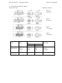
4.2. PROGRAMMING OF TACHOMETERSPEEDOMETER (12)
To program tachometer-speedometer use
control panel (19) and do the following:
- take cover (4) off panel (19);
- press button (I) to enter programming
mode;
1. program
tachometer-speedometer
according to the number of pinion teeth
where diesel revolutions sensor is
installed (parameter “I”); to this end:
- press button (I) and enter figure “I” on
display (7) of tachometer-speedometer
(12);
- press button (2) and set the value of the
number of teeth (Z) according to the
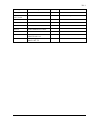
below given table:
Parameter Value
Table 4.2
N
of
teeth (Z)
69
23
Tractor model
MTZ 570; 590; 80; 1; 890;
900; 922; 950; 1025 and
modifications thereof
MTZ 1021, 1221; 1222; 2022
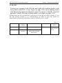
2. Program radius of rear wheel rolling
(parameter “2”):
- press button (1) and enter figure “2” on
display (7);
- press button (2) and enter value Rk
according to table below.
Program the diesel model (parameter <3>);
- Press button (1) and enter figure <3>on
display
(7)
of
the
tachometerspeedometer;
- Press button (2) and enter the required
diesel model
NOTE: If data on the type of tires assembled
is not available, before putting the tractor in
operation one can measure Rk as distance
from wheel axle to support surface. Then
enter on display coded number, closest to
value measured.
Seven seconds after programming is over the
device automatically is set in the operation
mode. Put the panel cover in place.
MTZ 2022/2022V - Operation manual.
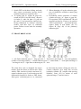
Section 5. Design and operation
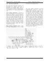
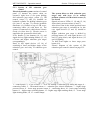
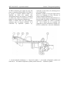
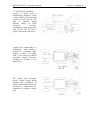
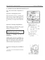
5. DESIGN AND OPERATION OF THE TRACTOR COMPONENTS
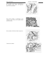
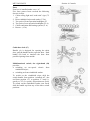
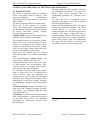
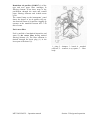
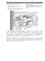
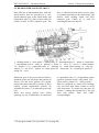
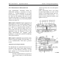
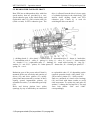
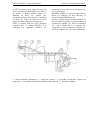
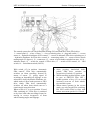
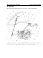
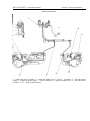
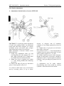
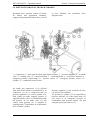
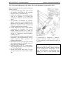
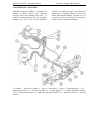
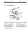
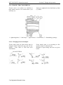
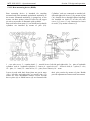
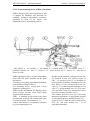
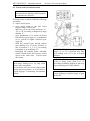
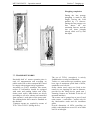
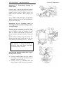
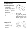
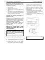
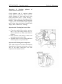
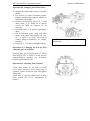
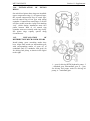
The front shaft end bears: pinion for driving
gas distribution mechanism, oil pump drive
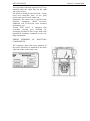
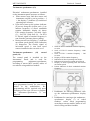
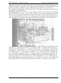
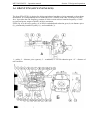
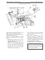
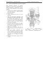
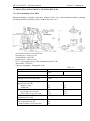
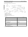
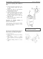
5.1. DIESEL ENGINE
The tractor is equipped with a six-cylinder,
pinion, water pump, generator and air
in-line, four-stroke diesel D-260.4*, with
conditioning generator (if available) drive
turbo-supercharging,
intermediate
pulley.
supercharged air cooling, direct fuel injection,
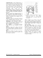
To reduce the level of crankshaft torsion
fluid cooling.
vibrations, the pulley is provided with fluid
The diesel is started with an electrical starter.
torsion vibration damper (3).
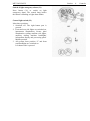
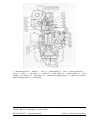
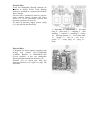
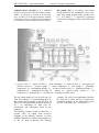
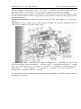
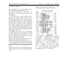
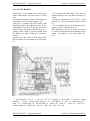
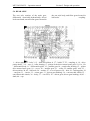
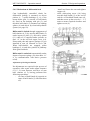
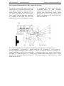
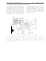
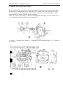
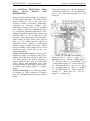
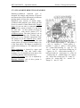
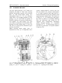
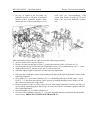
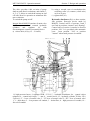
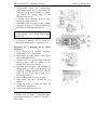
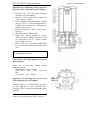
Diesel (pp. 47, 48) consists of a cylinder
Piston is made of aluminum alloy. The piston
block, two cylinder heads, crank mechanism,
bottom has combustion chamber. The upper
gas distribution mechanism, and also fuel and
section thereof is provided with two
air supply, lubrication, cooling, starting,
compression and one oil-control rings with an
electrical equipment systems.
expander. The upper compression ring is
Cylinder block (20) has a mono-block design
trapezoid-shaped and has barrel-like profile
and looks like a rigid cast iron casting.
coated with chrome; the second compression
ring is of the “minute” type. To accommodate
The boring block has six removable cylinder
the upper ring the piston is provided with
sleeves (15) made of special-grade cast iron.
“niresistive” insert (see figure on page 49).
Sleeves are installed in the cylinder block
along two centered belts. In the upper belt the
sleeve is fixed with a clamp, and in the lower
one it is sealed with two rubber rings
From below the cylinder block is covered
with cast oil crank case (1) made of aluminum
alloy.
Two interchangeable cylinder heads (18)
(one for three cylinders) are iron cast.
Cylinder heads have insert valve seats made
of heat-resistant and wear-resistant alloy.
Cylinder heads are provided with injectors
(14), page 48, (three for each head).
To seal space between heads and cylinder
block, a filler piece (19) of asbestos-steel
cloth is placed (page 47). Openings for
cylinder sleeves and oil duct are backlined
with sheet steel. During diesel assembly at the
manufacturer’s filler piece cylinder openings
are additionally backlined with fluoroplastic
rings.
Crank mechanism includes crankshaft (25)
with main and crankpin bearings, flywheel
(22), pistons (14), including rings and pins,
connecting rods (13).
Crankshaft is a steel seven-bearing structure
with counter-balances. Connecting rod necks
are provided with cavities for additional
centrifugal oil purification, covered with
threaded plugs
MTZ 2022/2022V – Operation manual
*) The tractor may be equipped with diesel D260.4C
Section 5. Design and operation
1 – oil crank case; 2 – oil mump; 3- torsion vibration damper; 4 – crankshaft pulley; 5 – fan drive
belt; 6 – cover of distribution pinions; 7 – stretcher pulley; 8 – generator drive belt; 9 – fan; 10 –
water pump; 11 – casing of thermostats; 12 – piston pin; 13 – connecting rod; 14 – piston; 15 –
cylinder sleeve; 16 – cover cup (2 pieces); 17 – cylinder head cover ( 2 pieces); 18 – cylinder head
(two pieces); 19 – cylinder head filler piece (one piece); 20 – cylinder block; 21 rear sheet; 22 –
flywheel; 23 – counter balance; 24 – cover; 25 0 crankshaft; 26 – piston cooling injector; 27- oil
receiver.
MTZ 2022/2022V – Operation manual
Section 5. Design and operation
1 – distribution shaft; 2 – pusher; 3 – valve; 4 – guide bushing; 5 – rod; 6 – turbo compressor; 7 –
rocker; 8 – roller; 9 – valve plate; 10 – dentils; 11 – inside spring; 12 – outside spring; 13 – fixed
member; 14 – injector; 15 – fuel pump*; 16 – manual fuel supply pump; 17 – plug for air removal
from fuel pump head; 18 – sealing ring.
*) Presently, distribution-type fuel pumps shown above are replaced with in-line fuel pumps
“Yazda”, Russia, or “Motorpal”, Czech republic.
MTZ 2022/2022V – Operation manual
Section 5. Design and operation
Connecting rod is a steel T-shape device. A
bushing is pressed in its upper head. Openings
are provided in the upper connecting rod and
sleeve section for piston pin lubrication. The
lower head consists of a lower connecting rod
section and a cover with a similar marking.
Connecting
rods’
covers
are
not
interchangeable. Besides, connecting rods are
marked by upper and lower heads, put on the
end face of upper connecting rod head. One
group connecting rods should be installed on
the diesel.
Inserts of main and crankpin bearings of
the crankshaft are thin-walled and made of
bimetal strop. Inserts have two sizes of inside
diameter according to the nominal size of
crankshaft necks.
Flywheel is made of cast iron and is fastened
to the crankshaft flange with bolts. A steel
toothed ring is compressed on the flywheel.
Mechanism of gas distribution consists of
pinions, inlet and exhaust camshaft, as well as
parts of installing and driving thereof.
The camshaft is a four-bearing structure
being rotated by the crankshaft via gear
pinions.
Pushers (2), page 48, are made of steel and
have spherical bottoms. Camshaft cams have
slight tilt that imparts rotational movement to
pushers.
Rods (5) of pushers are made of steel bar.
Spherical part coming inside the pusher and
the rod cup are tempered.
MTZ 2022/2022V – Operation manual
1- piston; 2- “niresist”-type insert; 3- upper
compression ring; 4 – the second
compression ring; 5- oil-control ring with
an expander.
Valves’ rockers (7) are made of steel and
sway on rollers installed in fixed members.
The rocker’s roller is shallow and has six
radial openings for lubrication of rockers. The
rockers motion along rollers is limited by
distance springs.
Inlet and exhaust valves (4) are made of
heat-resistive steel. They move in guide
bushings compressed in cylinder heads. Each
valve is closed by two springs: the outside
(12) and inside (11), which are fastened to its
rod by way of a plate (9) and dentils (10)
Sealing rings (18) installed on valves’ guide
bushings exclude oil trapping in diesel
cylinders via spacing between valves’ rods
and guide bushings.
Section 5. Design and operation
Diesel supply system consists of an air purifier, air intake pipeline, intake and exhaust manifolds,
turbo compressor, supercharged air cooler, muffler, fuel tanks,
fuel coarse and fine filters, fuel pump, injectors, high and low pressure fuel lines.
Supercharged air cooler
1 – booster pump; 2 – by-pass pipeline; 3 – fuel pump, 4- high pressure fuel lines; 5 – main filtering
element; 6 – control filtering element; 7 – air purifier; 9 – sleeve; 10 –turbo compressor; 11 – bypass; 12 – air purifier clogging light; 13 – exhaust pipe; 14 – muffler; 15 – injector; 16 – guard ring;
17 – fuel coarse filter; 18 – filler neck; 19 – fuel tank; 20 – fuel level float; 21 – coupler of sediment
drain; 22 – stop valve, 23 – drainage pipeline; 24 – pneumatic corrector pipeline; 25 – fuel fine
filter; 26 – sealing ring; 27 – bolt; 28 – air outlet plug; 29 – supercharged air cooler; 30 water
radiator ( for reference); 31 - input diesel manifold.
*) Diesels equipped with in-line fuel pumps have a fine filter with a paper filtering element in the
supply system.
MTZ 2022/2022V Operation manual `
Section 5. Design and operation
Donaldson Air purifier (G100317) is of dry
type and uses paper filter cartridges as
filtering element. It has three steps of dry
purification through the main and control
paper filtering elements and in-built mono
cycle/
The control lamp on the instruments’ panel
shows the degree of an air purifier clog up.
An electrical sensor of air purifier clogging up
operates at the manifold vacuum 459 +/-50
mm of water
Fuel coarse filter
Fuel is purified of mechanical impurities and
water by the coarse filter having meshed
filtering element (4). The filter sediment is
drained through the drain plug (1) in the
lower part of the barrel (3).
1 – plug; 2 – damper; 3 – barrel; 4 – meshed
reflector; 5 – scatterer; 6 try square; 7 – filter
body.
MTZ 2022/2022V – Operation manual
Section 5. Design and operation
Fuel fine filter
It has two changeable filtering elements (0)
adopted to diesels D-243. Each filtering
element is installed in a separate knock-down
filter-cartridge
Fuel fine filter is intended for multi-use purposes
under condition filtering elements and rubber
spacers (15, 16) are periodically replaced, and
operation regulations are observed.
To outlet air from the supply system a plug
(3) is provided in the filter body.
1 – input duct; 2 – exhaust duct; 3 – air outlet
plug; 4 – filter body; 5 – coupling; 6 – inlet
opening; 7 – bottom; 8 – coupling; 9 – clamp;
10 – filtering element; 11 – fuel outlet duct;
12 – spring; 13 – cup; 14 – nut; 15,16 –
spacer; 17 – escape plug; 18 – plug; 19 –
body.
Fine fuel filter
is designed for diesel engines equipped with
in-line
fuel
pumps
363.11110005404
(YAZDA, Russia), or PP6M10PIF-3493
(Czech republic). It has one changeable
filtering element installed in the body (19).
Injectors (15) of closed type with five
openings atomizer (see figure on page 50)
inject fuel.
MTZ 2022/2022V – Operation manual
Section 5. Design and operation
FUEL PUMP
High pressure fuel pump is of a distribution type*) and has two sections with fuel dosage by
means of supply end change, and a pneumatic anti-fume corrector. The fuel pump is driven by the
diesel crankshaft via gas distribution pinions.
1 - oil level plug; 2 – bushing; 3 – flange; 4 – cam shaft; 5 – main lever tie-bar; 6 – adjusting lever;
7 – metering drive bushing; 8 – bolt; 9 – start spring; 10 – cover; 11 – fuel supply coupling; 12 –
damper spring; 13 – damper body; 14 – damper piston; 15 – plunger bushing; 16 – high-pressure
couplings; 17 – spring; 18 – supercharging valve; 19 – technological plug; 20 – reverse valve; 21 –
plunger; 22 – meter; 23 – plug; 24 – tooth bushing; 25 –upper plate spring; 26 – upper governor
cover; 27 – governor shaft; 28 - <stop> screw; 29 – maximum revolutions screw; 30 – intermediate
pinion; 31 – lever bushing; 32 – control lever; 33 – governor spring shackle; 34 –main level
bearing; 35 – main lever; 36 – corrector cup; 37 – governor spring; 38 – limiter; 39 – check-nut; 40
–lever; 41 –corrector spring; 42 - check nut; 43 – corrector tie-rod; 44 – lever; 45 – check nut; 46 –
pneumatic corrector cover; ,47 – diaphragm; 48 – spring; 49 – pneumatic corrector tie-rod; 50 –
corrector body; 51 – check-nut; 52 – corrector lever; 53 – plate; 54 – bearing; 55 – corrector lever
axis; 56 – governor bushing; 57 – splint; 58 – driven pinion; 59 – supercharged pump drive shaft;
60 –governor damping spring; 61 – governor shaft adjusting washer; 62 drive pinion; 63 drive
pinion; 64 – pump body; 65 – plunger pusher; 66 – pusher roller axis; 67 – pusher spring; 68 –
lower spring plate; 69 – pusher roller.
MTZ 2022/2022V – Operation manual
The fuel pump is aggregated with an all-mode
governor and a piston-type booster pump.
The governor has a fuel supply corrector, an
automatic fuel supply dresser, operating at
starting revolutions velocity, and connected to
the inlet diesel collector via an air conduct.
The booster pump is installed on the high
pressure pump body and is actuated by the
camshaft eccentric.
Turbo compressor
The turbo compressor uses exhaust gases
\energy to charge air into diesel cylinders. It
consists of a centrifugal one-step compressor
(6) and a radial centripetal turbine (1).
The turbine wheel (1) is made of heat
resistant nickel alloy welded to the rotor shaft.
The compressor wheel (6) is aluminum alloy
cast, being fastened to the rotor shaft by a
special nut (7)
The turbo compressor principle of operation
is that exhaust gases outgoing under pressure
from cylinders, pass through the exhaust
collector to the gas turbine chamber and,
being expanded, rotate the turbine wheel, at
the other end of which is the compressor
wheel.
Gases go out through the exhaust pipe.
The excessive air pressure behind the
compressor at the rated diesel operation mode
should be 0.07…0.10 MPa (0.7…1.0
kgs/cm2).
Section 5. Design and operation
To remove air from the supply system, the
manual, booster, piston –type pump (1) and a
plug (see figure on page 50), as well as a plug
(see figure on page 48) installed in the fuel
pump head.
To supply fuel use pedal (24) (see figure on
page 27) or lever (29) (see figure on page 28).
To stop the diesel with an in-line pump use
lever (26a).
To lubricate the fuel pump parts use diesel
lubrication.
1 – turbine wheel and shaft; 2 – turbine body;
3 – bearing; 4 – oil deflector; 5 – sealing ring;
6 – compressor wheel; 7 – special nut; 8 –
bushing; 9 – diffuser; 10 – disk; 11 –
compressor body; 12 – stop ring; 13 – fixing
element; 14 – medium body; 15- bushing.
MTZ 2022/2022V – Operation manual
Section 5. Design and operation
________________________________________________________________________
SUPERCHARGED AIR COOLER
(see figure on page 50)
Supercharged air cooler (SAC) (29) is
connected to the turbo compressor (10) and
inlet diesel collector (31) by way of air
manifolds and hoses.
SAC is an air heat exchanger consisting of the
core in the form of aluminum pipes, tanks and
manifolds. It is installed in front of water
radiator and attached to radiator poles. Air is
conducted to the SAC from the turbo
compressor and cooled, improving diesel
power and economic characteristics, and then
comes to the diesel inlet collector
MTZ 2022/2028 - Operation manual
Section 5. Design and operation
LUBRICATION SYSTEM is of a combined
design; some parts are lubricated under pressure,
others – by spraying. It consists of an oil pump
(20), oil filter (2) with paper filtering element,
centrifugal oil filter (14), fluid-oil heat-exchanger
(3). Lubrication system diagram is shown below.
Oil pump (20) is of pinion, one-section
design driven by the crankshaft. It gas a bypass valve being opened under pressure over
0.7…0.74 MPa (7…7.5 kgs/cm2), by-passing
oil from the charging cavity to the inlet suck
cavity.
1- by-pass valve; 2 – paper oil filter; 3 – heat exchanger; 4 – main oil duct; 5 - emergency oil
pressure sensor; 6 – pressure gauge; 7 - turbo compressor; 8 – fuel pump; 9 – pneumatic
compressor; 10 – intermediate pinion; 11 – oil duct of rocker axle; 12 – distribution shaft; 13 –
crankshaft; 14 – centrifugal oil filter; 15 – piston; 16 – piston cooling nozzle; 17 – oil
crankcase; 18 – drain plug; 19 – oil drain; 20 – oil pump;21 safety valve.
The oil pump intakes oil via oil pick-up (19)
from oil crankcase (17) and through ducts of
the cylinder block supplies to the full flow oil
filter (2) with a paper filter element, an part of
oil – to centrifugal oil filter (14) for
purification and subsequent drain in the
crankcase.
The filtering element of the oil filter has a
by-pass valve (1) which, with excessive
clogging of the filtering element, or when
starting cold diesel, is opened and supplies oil
to the oil dust by-passing the filtering
element. The valve is not adjustable. Besides,
the filter has a safety valve (21) adjusted to
sustaining pressure in the lubrication system
at 0.28…0.45 MPa (2.8…4.5 kgs/cm 2)
MTZ 2022/2022V – Operation manual
Section 5. Design and operation
During diesel operation oil, purified in the filter and cooled in the fluid-oil heat exchanger (3), via
cylinder block ducts is supplied to all bearings of the crankshaft and the distribution shaft. Via
nozzles (16) built-in main support of the cylinder block, oil is supplied to cool pistons (15).
Oil is supplied for lubrication of turbo compressor (7) and tractor’s pneumatic system from heat
exchanger (3) via individual ducts.
The cooling system *) of the diesel is of fluid closed type with forced circulation of cooling fluid.
It consists of the water jacket, a water pump, a radiator, a fan with an automatically controlled
viscosity pipe coupling, two thermostats, expansion tank with a radiator plug having steam air
valve, connecting rods and drain valves. The water pump with a viscosity friction coupling is shown
on the next page. The expansion tank is provided with a measuring glass to control coolant level.
1 - a diesel fastening arm; 2 – water pump manifold;3 - shock absorber of water radiator rubber
suspension; 4 – water pump drive belt; 5 – lower radiator tank; 6 – radiator water drain valve; 7 –
water pump belt tensioning roller; 8 – automatic tension spring; 9 – automatically switched fan with
a coupling; 10 – water radiator core; 11 – stopper of the forced fan switching mechanism; 12 –
upper radiator tank; 13 – water radiator fill-in neck cover; 14 – steam air pipe; 15 – expansion tank;
16 – cooling fluid temperature sensor; 17 – emergency sensor of cooling liquid temperature; 18 –
indicator of diesel cooling fluid temperature (including emergency temperature signal lamp); 19 –
water pump impeller; 20 – water jacket cavity of the cylinder block; 21 – water intake pipe; 22 –
ducts for directing flows of cooling fluid system; 23 – eye-bolt; 24 – plug; 25 – valve to drain fluid
from cylinder block ( installed on the opposite side of the diesel); 26 – fluid-oil heat exchanger.
*) deaeration and compensation loop type.
MTZ 2022/2022V – Operation manual
Thermal state is adjusted by changing the
amount of air passing through the cooling
system radiator, and also by two thermostats.
The cooling liquid temperature is controlled
using the remote thermometer, sound and
light signal instruments, sensors of which are
located in the thermostats’ body cover. The
rated diesel temperature mode corresponds to
cooling liquid temperature of 80…97 °C.
The fluid-oil heat exchanger built-in diesel
body cools diesel lubrication oil. To control
oil pressure, the heat exchanger exhaust
flange is provided with operation and
emergency pressure sensors. The rated diesel
temperature mode in what concerns
lubrication oil is 80…120 °C.
Radiator is of pipe and plate design and is
provided with an in-fill neck with no steam
air valve.
The fan has two operational modes:
automatic;
forced.
The automatic mode is ensured by the
viscosity friction coupling in the following
way: at cooling fluid temperature below 80 °C
, the return spring (7) keeps valve (10) closed,
and viscous fluid overflows to the reserve
coupling cavity, dive (11) and driven disks
(13) rotate with space in-between, providing
minimum fan rotation. In this case fan
rotation should not exceed 1500 rev/min.
Section 5. Design and operation
1 – fan blade; 2 – driven cover; 3 – stoppage
opening; 4 – stopper nut; 5 – stopper; 6 – end;
7 – return spring; 8 –yoke – 9 pusher; 10
valve 11- drive valve; 12 – coupling; 13 –
driven disk; 14 – drive shaft; 15 – water pump
pulley; 16 – water pump; 17 - rod
When cooling liquid temperature exceeds 80 0
C, the thermal sensitive element by means of
rod (17) and pusher (9), overcoming return
spring (7) opens valve (10). Viscous fluid
overflows to the operation cavity via drive
disc opening, and fills the space between dive
and driven disks, resulting in these disks
coupling, thus switching the fan in the
operation mode.
CAUTION! Switch on forced fan
operation mode when the pneumatic
system compressor is operational.
MTZ 2022/2022V - Operation manual
Do the following to change for the forced
(permanent) fan operation mode:
unscrew nut (4) of stopper (5) by 4…5
turns (about 5 mm);
manually rotate the fan until stopper
enters opening (3) of drive disc (11). If
Section 5. Design and operation
needed, press stopper (5) with a hand to stop
drive and driven discs.
Electrical equipment and starting system
The diesel is equipped with 1250 W and 14 V
generator.
1 – lead of the additional storage battery charge; 2 – terminal “+14 V”; 3 – terminal “D” (lead of
excitation winding end); 4 – lead of the excitation winding start; 5 – terminal “+28V”; 6 – rectifier
block; 7 – rotor; 8 – stator; 9 – stator coil; 10 – excitation coil; 11 – generator tightening bolt; 12 –
generator coil cup; 13 – generator front cover; 14 – fan; 15 – pulley; 16 – one-time grease closed
type ball bearings; 17 – rotor bushing; 18 – 14 V integral voltage regulator; 19 – terminal “W”; 20 –
28 V integral voltage regulator; 21 – cover of the regulation device.
Generator is of brushless inductive design, alternating current with two levels of voltage regulation
(14 and 28 V) with built-in power and auxiliary rectifiers and electronic voltage regulators. The
generator is intended for operation within an electric equipment system and diesel start at rated
voltage of 24 V and vehicle-borne voltage of 12 V.
MTZ 2022/2022V – Operation manual
Section 5. Design and operation
The first voltage level (terminals “+14 V”, “D”; “W” (“-”) is used for the vehicle-borne supply line,
the second voltage level (terminal + 28 V) is used for additional storage battery charging.
The generator can operate both in an independent excitation mode (with a storage battery), and in
the self-excitation mode (without storage battery). The generator is driven by the wedge belt from
the crankshaft pulley.
The diesel starting device consists of an electric starter 20.3708 with voltage of 23 V and power
5.9 kW.
The starter is a direct current electric motor of series excitation. It is remotely switched on by way
of an electric- magnetic relay and a starter switch.
1 – yoke; 2 - half-ring; 3 – starter cover; 4 – starter switching lever; 5 – switching lever axle; 6 – the
core of the traction relay and a shackle 7 – traction relay; 8 – contact disc with a rod; 9 – contact
bolts; 10 – rear starter cover; 11 – a spring; 12 – a brush; 13 – a collector; 14 - safety housing; 15 –
starter body; 16 – starter armature; 17 – a spring; 18 – coupling of free drive movement; 19 –
driving pinion; 20 armature shaft; 21 – bushing.
To start the diesel at low ambient temperature incandescent bulbs are used that heat pre-start air
inletting diesel cylinders.
MTZ 2022/2022V – Operation manual
Compressor
To drive trailer’s pneumatic brakes and tires
inflation the diesel is equipped with a piston,
one-cylinder, one step compressor. During
tractor’s operation in agricultural works, not
requiring compressed air power, the
compressor should be switched off.
The compressor is installed on the distributor
cover flange and is driven by the fuel pump
driving pinion. The compressor is cooled by
air. When the compressor is in operation, the
fan should be switched to the forced mode.
The compressor has capacity of 180 l/min at
back pressure of 0.6 MPa (6 kgs/cm2) and
rated diesel rotation frequency.
Section 5. Design and operation
Segments
Expanders
NOTE: When the compressor is in
operation, the diesel fan should be switched
to the forced mode.
1 – roller bearing cut; 2 – intermediate
compressor driving pinion; 3 – compressor
switching shaft with an eccentrically located
pin; 4 – compressor switching lever; 5 – shaft
fixing arm; 6 – spring; 7 – fixing arm bolt; 8 –
crankcase; 9 – crankshaft and a driving
pinion; 10 – connecting rod; 11 – piston pin;
12 – plate; 13 – forced drought valve; 14 –
limiter; 15 – cylinder head; 16 – inlet valve;
17 – piston; 18 - compression rings; 19 –
segments, expanders ( oil-control ring); 20 –
cylinder; 21 – sealer; 22 – spring.
MTZ 2022/2022V – Operation manual
Section 5. Design and operation
5.1.1. Possible diesel failures and methods of removal thereof
Failure, appearance
Correction method
Diesel doesn’t start
Pump the system with fuel manual pipe.
Remove air ingress in the fuel system.
Air in the fuel system
Fuel pump failure
Remove the fuel pump from the diesel and
take it for repair
Fuel filters are clogged
Rinse coarse fuel filter and replace filtering
elements of fine fuel filter.
Diesel doesn’t develop capacity
Fuel pump control lever doesn’t come
Adjust fuel pump control bars
to the end
`
The filtering element of the fine fuel
filter is clogged.
Replace the filtering element of the fine fuel
filter
Injectors failed.
Find out failed injectors, rinse and adjust.
Injection advance angle is not properly
Set the required angle of injection advance.
adjusted
Diesel smokes in all operation modes
A. Black fumes get out the exhaust pipe
Diesel air purifier is clogged.
Carry out air purifier maintenance.
Injector nozzle needle floats.
Find out failed injector, rinse or replace the
nozzle, adjust the injector.
Fuel pump is failed.
Take off the fuel pump and take it for repair to
the workshop.
B. White fumes get out the exhaust pipe
The diesel is overcooled
Heat up the diesel, during operation keep
cooling fluid temperature within 70 –95 °C
Water entrapped in fuel.
Replace fuel.
No space between valves and rockers
Adjust space between valves and rockers.
Angle of injection advance is not
properly adjusted.
Set the recommended angle of injection
advance
MTZ 2022/2022V – Operation manual
Section 5. Design and operation
Continuation of table 5-1
Failure, appearance
Correction method
C. Blue fumes get out the exhaust pipe
* Oil entrapped in the combustion chamber
due to wear of piston group parts.
Replace worn out parts of the piston group.
* Excessive oil in the diesel crankcase
Drain out excessive oil having set the level
according to the upper mark of the oil metering
rod.
Diesel overheats
* Insufficient amount of cooling liquid in
the system
Fill in the cooling liquid to the normal level.
* The radiator is dirty outside.
Clean the radiator.
* Dirt and scale in the cooling system.
Clean and rinse the cooling system off dirt
and scale.
* The thermostat valve doesn’t open
completely
Replace one or two thermostats
* The fan belt is not tight enough:
* The tightening device spring is broken;
* Jamming of the tightening pulley at the
lever axle.
Replace the spring. If that is not possible,
temporarily interlock the tightening device,
having tightened generator bar and tightening
pulley with a bolt an a nut. But first, tighten the
belt.
Dismantle the tightening device and correct the
failure
* Oiling of the fan and pulley’s belt.
Remove the driving belt, and clean oil traces
from belt and pulley’ surface.
Underrated oil pressure of the heated diesel
* oil indicator or sensor are failed.
Replace the oil pressure indicator or sensor
after gauging oil pressure with a reference
gauge.
*Oil conducts sealing is no good.
Find out the sealing problem and correct it.
* Oil pump is failed.
Find out the problem and correct it.
* Oil level in the diesel crankcase
is lower than rated value
Fill –in oil to the upper mark of the oil
measuring rod
* Jamming of the safety valve in the
oil filter body
Rinse the valve and adjust pressure in the
lubrication system.
* Excessive wear of the coupling
“crankshaft necks – bearings”.
Correct the trouble.
MTZ 2022/2022V
- Operation manual
Malfunction, appearance
Section 5. Design and operation
Continuation of table 5-1
Correction method
Turbo compressor
* Rotor of the turbo compressor doesn’t
rotate (no typical high-tone sound):
* Foreign matter hinder rotor rotation
Take off inlet and exhaust manifolds, remove
foreign matter.
* Rotor is jammed in the bearing.
Replace turbo compressor.
* Increased oil injection on the side of
the compressor or turbine, leaks from
oil sealing of the turbo compressor.
Take the turbo compressor off the diesel
and send for repair.
Starter
* During starter switching diesel crankshaft
doesn’t rotate (or rotates very slowly):
* storage battery clamps are not properly
Strip lugs and tighten clamps.
tightened, or wiring lugs are oxidized
* storage battery discharged lower
allowable limit
Charge or replace the battery.
* collector and brushes are dirty;
Clean collector and brushes.
*brushes have poor contact with collector; Take the starter off the diesel, scrape the
collector, or replace brushes if worn out.
*burnt starter relay contacts;
Scrape starter relay contacts.
*starter driving coupling slips (worn out
coupling rollers, or yoke cracked);
Replace starter drive.
* After diesel start, the starter remains switched on:
* the power disc is stuck to contact bolts
of starter relay;
Stop the diesel, switch off the battery and
clean contacts of the traction relay.
* driving pinion stays engaged to the
Replace the return spring of the push lever.
flywheel ring due to break of push
lever spring.
MTZ 2022/2022V – Operation manual
Section 5. Design and operation
Continuation of table 5.1
Correction method
Failure, appearance
Generator
* Voltage indicator doesn’t show charging
after diesel start and further on during
operation:
*positive clamp torn off, or short-circuited
on the generator body;
Disconnect the rectifier, weld and insulate
*excitation coil open-circuit
damaged site, and if the trouble is not
corrected, replace the excitation coil.
*short -circuit in straight and opposite
rectifiers’ polarity of one phase;
Replace the rectifier.
*short-circuiting of one of stators phases
on generator body;
*generator doesn’t develop full capacity:
* torn off wiring leading to the regulator;
* one of stator’s phases torn off;
* turn short-circuiting of the stator winding;
* turn short-circuiting of the excitation coil
winding.
* Generator noise:
* driving belt slips or is too tight;
* ball bearings are worn out;
Replace the starter.
Solder and insulate the damaged site.
Replace the stator.
Replace the stator.
Replace the excitation coil.
Adjust driving belt tension.
Replace ball bearings.
MTZ 2022/2022V – Operation manual
Failure, appearance
Section 5. Design and operation
Continuation of table 5-1
Correction methods
The units of the automatic fan clutch control system
* If water temperature exceeds 97 °C at the
diesel outlet, the cooling system fan doesn’t
switch on , or with water temperature below
70 °C, the cooling system fan doesn’t
switch off:
fault with thermal power sensor, or a fan
clutch.
*remove fan clutch;
*press the rod in the water pump to the end,
and measure how far it extends;
*start the diesel and heat it to bring water
temperature at the outlet to 80-85 °C;
stop the diesel and measure rod extension
from the water pump;
1. If extension didn’t increase against the
initial, replace thermal power sensor;
2. If extension increased by 6-8 mm, replace
fan clutch, and send faulty clutch for repair. I f
the clutch can’t be replaced, interlock it by the
given above method (see “ The diesel cooling
system”).
Tachometer-speedometer
*During tractor travel the tachometerspeedometer shows constant speed of 0.2
km/h:
*One of speed sensors failed.
Replace sensor
*During diesel operation tachometer
doesn’t indicate rev/min:
*open-circuit from phase winding to
Correct the trouble.
tachometer – speedometer;
*no signal from generator phase winding. Replace the generator.
MTZ 2022/2022V – Operation manual
5.2. THE CLUTCH
Diesel flywheel (1) is provided with dry, twodisc clutch of permanently closed type.
The driving elements of the clutch are
flywheel (1), pressure clutch plate (3) and
middle plate
(2) with three pins on the outside surface,
coming in special flywheel grooves (1),
driven clutch elements are two driven discs
(24) provided with torsion vibration damper
(90) installed on the power shaft (7). Required
pressure effort of friction surfaces of driving
and driven coupling parts are provided by
nine outside and nine inside springs (22). An
elastic element is installed between floating
bushing (8) connected to the driving shaft (9),
and support plate (12).
The middle disc (2) has lever mechanisms
(11) that ensure disc (2) equal distance setting
between flywheel friction surface (1) and
pressure clutch plate (3). Yokes (13) serve as
squeeze clutch levers supports.
They are fixed on the support disc by way of
adjusting nuts and fixing washers (14).
Clutch is engaged and disengaged by shifter
(17) and squeezing bearing (16) moving along
bar (18). Shifter yoke (19) with roller (20) are
connected to clutch pedal via hydraulic static
drive.
Squeeze bearing (16) is lubricated by means
of the press-grease cup screwed in the shifting
neck.
Section
5.
Design
and
operation
The grease cup is on the left side of the clutch
body. To get access unscrew the plug.
1. – flywheel; 2 – middle disc; 3 – pressure
clutch plate; 4 – driving shaft; 5 – bushing; 6
– bearing; 7 – power shaft; 8 – floating
bushing; 9 – torsion vibration damper; 10 –
squeeze lever; 11 – lever mechanism; 12 –
support disc; 13 – yoke; 14 – washer; 15 –
nut; 16 – bearing; 17 – shifter; 18 – shifter
bar; 19 – switch off yoke; 20 – control roller;
21 – cup; 22 pressure clutch springs; 23
insulating washer, 24 – driven discs.
MTZ 2022/2022V – Operation manual
Section 5. Design and operation
5.2.1. CLUTCH BODY
Clutch body (30) contains drive and driven
shafts with pinions, oil pump drives of HLS
and
transmission hydraulic system. Drive shaft (4)
is mounted on two bearing supports. The
shaft has a toothed ring and splints with
installed pinion (5) forcing pinion (19) of the
independent PTO (18) of driving the driven
shaft to rotate, and pinion (8) that drives oil
pumps. Power shaft (1) passes through shaft
(4) which via splint pushing (6) transmits
torsion
moment from the clutch to GB input shaft.
Driven shaft (18) is mounted on two bearings
(17,
27) in clutch and GB bodies. The shaft of
needle bearings bears (25) driven pinions (19,
24) of
two-speed independent PTO drive. Fixed
pinions (19, 24) are connected with the shaft
by
way of toothed clutch (23) being moved by
means of yoke (20) and roller (21).
HLS oil pump is driven by means of pinions
(5) and (8), and transmission hydraulic system
pump – by pinions (5), (8) and shafts (15),
(12).
1 – power shaft; 2 – bar; 3 – 3, 10, 14, 17, 25, 27 – bearings; 4 – drive shaft; 5 – pinion; 6 - splint
bushing; 7 – cover; 8 – pumps drive pinion; 9 , 15 – shaft-pinion; 11 – nut; 12 – shaft-pinion; 13 –
shaft – 16 – sealing ring; 18 – driven shaft; 19 – pinion; 20 – yoke; 21 – roller; 22 – cover; 23 –
toothed clutch; 24 – pinion; 26 – cup; 28 – roller; 29 – yoke; 30 – body.
MTZ 2022/2022V – Operation manual
Section 5. Design and operation
CLUTCH DRIVE
The clutch drive is intended for clutch control
both for forward travel and driving in reverse.
The clutch drive is of hydraulic static design
with suspended pedals and a hydraulic
booster.
The drive consists of main cylinders (1) ( for
forward travel), and 19 – (for driving in
reverse), suspended pedals 10 (forward travel)
and 12 ( driving in reverse), valve 21 ( for
automatic
changing tractor forward travel mode to
reverse mode, and visa versa), operation
cylinder 28, hydraulic booster 31, lever 40,
tank 2, connecting pipelines and oil conduits.
Hydraulic booster 31 is of static model and is
intended for reduction of effort applied on
pedals 10 and 12 in the process of clutch
disengagement. It is connected via oil conduit
11 to the transmission hydraulic system
pump, and via hose 41 to clutch body drain.
In the forward movement mode when
pressing pedal 10 breaking fluid from main
cylinder 1 via pipeline 20 is supplied to cock
21. In cock 21 piston moves to the end right
position closes pipeline inlet 22. Then via
hose 23 braking fluid is supplied to operation
cylinder 28, thus moving piston 29. Piston 29
actuates pusher 30 of hydraulic booster 31,
resulting in hydraulic booster 31 operation,
extension of the piston and tie-bar 36, shifting
lever 40, which is via roller pushing the
clutch, leads to disconnection of the engine
from transmission.
In the reverse operating mode, when pressing
pedal 12, braking fluid via pipeline 22 from
main cylinder 19 is supplied to cock 21. In
cock 21 the piston moves to the end left
position and closes pump line inlet 20. Then
braking fluid via hose 23 is supplied to wheel
cylinder
28, performing described above functions.
In the clutch drive system “Neva M” TU
2451-053-36732629-2003, or “ROSDOT”
TU-004-36732629-99 braking fluids are used.
Transmission
Free
wheeling
Clutch body
Free
wheeling
CLUTCH CONTROL
1 – forward movement main cylinder; 2 – tank; 3 – spring; 4, 17 –bolt; 5, 7, 15, 18, 25, 37 – nut; 6, 13, 30 –
pusher; 8;, 16, 38 – yoke; 9, 32, 39 – pin; 10 – forward travel clutch pedal; 11 – oil conduit; 12 – reverse
mode clutch pedal; 14 – sheathing; 19 – reverse mode main cylinder; 20, 22 – pipe line; 21 – cock; 23 –
hose; 24 – support; 26 – by-pass valve; 27 – safety cup; 28 – operation cylinder; 29 – piston; 31 – hydraulic
booster; 33, 34 – arm; 35 – pull out spring; 36 – tie-bar; 40 – lever; 41 – hose.
MTZ 2022/2022V
Adjustment of clutch control
There are several stages of clutch control
adjustment:
1. Adjustment of clearance between a
piston and pusher 6 of main cylinder
piston 1 (forward travel)
- insert pusher 6 of main cylinder 2 in
yoke 8, having observed distance B,
then tighten nut 7.
- by screwing and unscrewing bolt 4 to
set clearance between piston and
pusher 6 of main cylinder piston 2,
adjust free pedal movement 10 to
within 6…12 mm (as measured by
cover center);
- tighten check nut 5.
2. Adjustment of clearance between piston
and main cylinder piston pusher 19
(reverse mode operation);
- take off cover 14;
- unlock pusher 13;
- insert main cylinder pusher 13 in yoke
16, having observed distance B;
- tighten nut 15 and put on cover 14;
- by screwing and unscrewing bolt 17 to
ensure clearance between piston of
main cylinder piston 19 pusher 13,
adjust pedal 12 free travel within
6…12 mm (as measured by cover
center);
- tighten check nut 18.
3. Adjustment of clutch shifter free travel:
-
-
-
remove spring 35;
disconnect tie-bar 36 from lever 40,
pulling pin 39 out;
unlock yoke 38;
turn lever 40 anti clock-wise to the
end of pressure bearing to squeeze
levers and, turning yoke 38, align
lever and yoke openings;
tighten yoke 38 by 5…5.5 turns and
connect to lever 40 by means of pins
39;
tighten check nut 37, secure pin 39
with a cotter pin, put spring 35 in
place.
4. Adjustment of clearance between piston
29 of cylinder 28 and pusher 30 of
hydraulic booster 31:
-
-
Section 5. Design and operation
- remove wheel cylinder 28 from arm
33,having pulled out pin 32;
set piston 29 in cylinder 28 to end
right position up to the cover;
set piston 29 of cylinder 28 until it
smoothly touches pusher 30 of
hydraulic booster 31, and by screwing
or unscrewing support 24, align
support and arm openings 33;
screw in support 25 by ½ turns, place
pin 32, tighten it with a pin, tighten
check nut 25.
Circulate oil through clutch control hydraulic
system.
MTZ 2022/2022V
Circulating oil through clutch control
hydraulic system
Before the operation fill braking fluid in tank
2 of forward travel main cylinder, and
compensation chamber of main cylinder 19
for reverse movement mode.
1.To circulate oil through the hydraulic
system for forward travel, do the following:
-
-
-
-
fill braking fluid in tank 2 to level
“MAX”;;
take safety cup 27 off cylinder 28 and
put rubber hose on by-pass valve head
26, having dipped it in braking fluid
reservoir;
press clutch pedal several times;
keeping it pressed, unscrew by-pass
valve 26 by one fourth of the turn and
let excessive braking fluid with air
bulbs out into the braking fluid
reservoir;
tighten by-pass valve 26 and release
clutch pedal;
pump the system until air bulbs in
braking fluid being drained disappear
completely;
take the hose off and put safety cup 27
in place;
check braking fluid in tank 4 and
refill, if necessary.
2. To circulate oil in the hydraulic system
for reverse movement mode, do the
following:
-
-
take case 14 of main cylinder 19;
check braking fluid in main cylinder
compensation chamber 19, which
should not be less than 15 mm lower
from upper compensation chamber
rim;
the order of bleeding the hydraulic
system is similar that of forward travel
mode.
Section 5. Design and operation
3. Checking hydraulic system bleeding as
per item 1.
CAUTION!
During hydraulic system
bleeding:
- for forward travel keep braking
fluid level in tank 2 within marks
“MIN” and “MAX”;
- for the reverse movement mode
keep braking fluid level in main
cylinder compensation chamber 19
not lower than 15 mm from
compensation chamber upper rim.
Upon checking clutch control adjustments,
check noise of clutch disengagement; to this
end:
- start the tractor and set diesel rotation
frequency to 1400 +/- 100 rev/min;
- pull the parking brake back to the full;
- press clutch pedal to the full and in at
least 5 seconds shift GB gear, which
should be noiseless.
If this requirement is not observed, check
adjustments anew.
MTZ 2022/2022V
Section 5. Design and operation
Possible clutch malfunctions
Table 5-2
Malfunction, appearance
Correction methods
GB gears are shifted with grinding sound ( not full clutch disengagement)
Clutch control is not adjusted
Make adjustments
Squeeze levers are out of level
Make adjustments
Driven discs’ bushings jam in power shaft Clean and grease cotter pins. If worn out or
cotter pins
damaged, replace discs or the power shaft.
Increased wobbling of driven discs’ blades
Replace discs
Flywheel bearing is destroyed
Replace the bearing
Air entrapped in the system
Find out the trouble. Bleed the hydraulic dive
system
Loss of pressure in operation cavities of main Replace sealing rings. Bleed the system.
and operation cylinders due to sealing rings
damage
Oil leakage through sealing rings of the Replace sealing rings in the hydraulic booster
hydraulic booster.
Clutch slips ( not full clutch engagement)
Clutch control is not adjusted
Make adjustments
Oiling of driven discs lining and adjacent Remove causes of oil trapping. Rinse oiled
friction surfaces
surfaces with benzene.
Lining of clutch driven discs is worn out
Replace lining or discs in assembly
Shrinkage of pressure springs
Replace springs
Jamming of main and operation cylinders’ Replace sealing rings. Bleed the system
pusher due to swelling of sealing rings
The hydraulic drive system is impossible to bleed in the reverse mode
(MTZ – 2522V/2822V)
Damage or wear out of the sealing ring of Replace sealing rings. Bleed the system.
main cylinder rod of the reversing mechanism
MTZ 2022/2022V – Operation manual
Section 5. Design and operation
5.3 GEAR BOX
The gear box is of mechanical, step-wise,
permanently clutched pinions, range-type
(four front travel ranges and two ranges of
reverse movement mode) design, with six
gears within each range shifted by means of
synchronizers. The gear box provides 24
gears for forward travel and 12 gears for
reverse movement, as well as front drive axle
drive.
1 – intermediate shaft; 2, 4, 14, 30, 33, 46, 49 – nuts; 3 – main drive; 5, 7, 8, 13, 20, 22, 23, 31, 34,
35, 38, 39, 43, 44, 50, 51, 52, 54, 55, 56 – pinions; 6, 12, 27, 53 – synchronizers; yokes’ body; 10,
18 – yokes; 11- hydraulic cylinder; 15 – ball fixing element; 16, 17 – levers; 19 – drag bar; 21, 36,
40 – bushings; 24, 45 – roller bearings; 25, 48 – adjusting washers; 26 – main output shaft; 28 –
shaft of pinions block; 29 – shaft of independent PTO drive; 32 – shaft of reduced gears and reverse
movement; 37, 42 – toothed clutches; 41 – stop ring; 47 – shaft; 57 – GB body.
MTZ 2022/2022V – Operation manual
5.3.1. Gear box design
The gear box (see figure on page 72) consists
of the body, gear block, reduced gears and
reverse movement shaft; pinions block; main
output shaft – a pinion; control mechanism an
hydraulic system.
Gear assembly consists of main output shaft
that bears drive pinions (8), (13), (5) and (7)
installed on needle bearings. They provide
shifting of gears 3, 4, 5, and 6
correspondingly, and 1 and 2 gears shifting
pinions are made as one assembly with shaft
(3).Shaft splines carry two synchronizers (6)
and (12), shifting gears 3, 4, 5 and 6.
Countershaft (1) bears with interference
driven gears (51), (50), (56) and (55) for gears
3, 4, 5 and 6 correspondingly are installed on
needle bearings. Shaft splines bear
synchronizer (53) for switching gears 1 and 2.
Reduced gears and reverse movement shaft
(32) has pinion (39) of forward travel ranges I
and II, and pinion (35) of reverse movement
ranges I and II. Splined bushing (40) bears
movement reducing pinion (43). Driven
pinion (44) is installed on splines of shaft
(47). If movement reducer is not installed,
pinion (44) is connected to reduced gear shaft
via pinion (43) and splined bushing (40).
Bushing (40 is connected to shaft (32) by
means of splines, and pinion (43) is fixed on
bushing (40) by retaining ring (41) to prevent
its axial travel.
Toothed coupling (37) serves to connect
pinions (35) and (39) to the shaft.
Pinion assembly shaft (26) bears pinions
(34) and (38) installed on splines. Pinion hub
(34) has FDA diving pinion (31) installed on
needle bearings.
Main output shaft-pinion (26) is installed in
GB case on coned roller bearings (24) and
(45). They are adjusted by means of washers
(48), and main output shaft (26) extension
(dimension 19.4 -0.13) is adjusted by selecting
of adjustment washer (25). The shaft has
immobile FDA driving pinion (23). The hub
has driven pinion (22) installed on needle
bearings. Bushing (21) carries driven pinion
(20) installed on needle bearings. Shifting
Section 5. Design and operation
between pinions (20) and (22) is effected by
way of synchronizer (27)
Parts’ assemblies on all shafts are tighten by
nuts (2), (4), (14), (30), (33), (46) and (49).
MTZ 2022/2022V –Operation manual
5.3.2 GB control mechanism
The GB control mechanism consists of a
mechanism for shifting gears and a
mechanism for shifting ranges with an
electric-hydraulic system for switching higher
("H”) and lower (“L”) stages of GB reduction
gear.
Gears shifting mechanism is mounted in
yokes’ case (9) (page 73), in control cover (9)
and body (57) (page 72). Gears are shifted by
means of yoke (16a) of GB shifting lever via
lever (11a), shaft (19) and lever (8a). The
yokes’ case has three carriers on which yoke
(10) (page 72) and levers are installed. To
prevent simultaneous shifting of two gears
locking steel balls are installed between
carriers. To fix carriers and yokes in neutral
and shifted positions, spring ball fixing
elements are provided.
Range shifting mechanism consists of yoke
(16), range shifting handle, lever (11), shaft
Section 5. Design and operation
(20) and levers (8). These parts are mounted
in control cover (9) and case (10).
The range shifting mechanism also has
electric-hydraulic system for control of
shifting higher and lower stages of the
reduction gear. It includes hydraulic cylinder
(11) (page 72), levers (16) and (17) , carrier
(19) and yoke (18), The reduction gear
control system is described below. Tooth-type
couplers (37) and (42) are moved by yokes
fixed on carriers (not shown). Synchronizer
(27) is switched by the electric-hydraulic
system. Position of tooth-type couplers (37)
and (42) in neutral and switched on state is
fixed by parts (6, 7a, 11) (page 77). In one of
its positions the synchronizer is fixed with a
ball with a spring and a pin. To exclude
simultaneous shifting of tooth-type couplers
(37) and (42), the GB case has locking steel
balls (6) and pin(7) (page 77).
1 – limiter; 2 – key; 3 – ball; 4 – nut; 5 – bolt; 6 – spring; 7 – bushing; 8, 8a – lever; 9 – cover; 10 –
case; 11, 11a – lever; 12 – pin; 13 – spring; 14 – sphere; 15 – sheath; 16, 16a – yoke; 17 – cover; 18
– pin; 19,20 – carriers; 21 – link.
MTZ 2022/2022V – Operation manual
5.3.3 System of GB reduction gear
control
Electric-hydraulic system consists of control
panel (1) situated the tractor cabin on
operator’s right, lever (3) for gears shifting
and reduction gear stages, sensor (5), GB
neutral, sensor (7) and (8), installed on
hydraulic cylinder for shifting reduction gear
(see item 11 on page 72), electric hydraulic
distributor (6), located on top of GB cover,
connecting cables (4) with shoes (9). The
system is connected to vehicle-borne electric
circuit via fuses box (2). Electric power is
supplied to the system after diesel start.
Lever handle (3) has buttons (10, 11) and
signal devices (light-emitting diodes) (13, 12)
of lower and higher reduction gear stages
correspondingly.
Panel (1) has signal devices (15, 14) of
switching of lower and higher stages of the
reduction gear and relay of reduction gear
control.
Section 5. Design and operation
The system allows to shift reduction gear
stages only with lever (3) in neutral
position (contacts of GB neutral sensor (5)
are closed)
Signals are sent to LEDs (13, 12) and (15, 14)
from relative pressure sensors (8 and 7).
After diesel start in the initial position lower
reduction gear stage is switched on. In this
case signal devices (13 and 15) should be
alight.
Higher reduction gear stage is shifted by
pressing button (11) with signal devices (13
and 15) going down, and signal devices (12
and 14) lighting.
To shift from higher to lower stage press
button (10).
Electric diagram of the system of GB
reduction gear control is shown on page 232.
1 – control panel; 2 – a box of fuses; 3 – lever for shifting of reduction gear shifts and stages; 4 –
connecting cables; 5 – GB neutral sensor; 6 – reduction gear electric distributor; 7 – higher stage
pressure sensor; 8 – lower stage pressure sensor, 9 – connecting shoes; 10 – lower stage switching
button; 11 – higher stage switching button; 12 – higher stage light emitting diode; 13 – lower stage
light emitting diode; 14, 15 – control lamps.
MTZ 2022/2022V – Operation manual
Section 5. Design and operation
Gears diagram of the tractor
MTZ 2022/2022V – Operation manual
Section 5. Design and operation
5.3.4 Diesel start locking
To rule out the possibility of starting diesel
with gear engaged, the tractor is equipped
with a special locking device
The locking device consists of switch (8)
installed in GB case on the left, balls (6) and
pins (7, 7a).
With range switched, the locking mechanism
disconnects contacts of the switch and breaks
the intermediate relay circuit of starter (1) and
starter relay tie-rod (5)
To adjust switch disconnection washers (9)
are provided.
BEFORE STARTING DIESEL, SET GB
RANGE SHIFTING LEVER IN THE
NEUTRAL POSITION!
1 – starter; 2 – generator; 3 – locking relay; 4 – starter switch; 5 – starter relay; 6 – balls of the
locking mechanism; 7, 7a – pins; 8 – lock switch; 9 – adjustment washers; 10 – range shift carriers;
11 – fixing element.
MTZ 2022/2022V – Operation manual
Section 5. Design and operation
5.3.5. Possible GB malfunctions
Table 5-3
Malfunction, appearance
Correction methods
Low pressure in the hydraulic system
Insufficient amount of oil in the Fill in oil to mark “P” on oil measuring
transmission case
window
Soiling of the hydraulic system mesh Rinse mesh filter
filter
Sticking of control valve of the filter- Rinse the valve of filter-distributor
distributor
High pressure in the hydraulic system
Sticking of control valve of the filter- Rinse the valve of filter-distributor
distributor
Oil drain ducts in the transmission are Rinse drain ducts
clogged
No pressure in the hydraulic system
Hydraulic system pump drive is switched Switch on the pump
off
Insufficient amount of oil in the Fill in oil to mark “P”
transmission
Noise when shifting gears
Clutch is not disengaged to the full
Wear out of coned
synchronizers and pinions
surfaces
Adjust the clutch
of Replace worn out parts
High noise
the Fill-in oil to mark “P”
Insufficient amount of oil in
transmission
Wear-out or breakage of bearings and Replace bearings and other elements
other transmission parts
MTZ 2022/2022V – Operation manual
Section 5. Design and operation
5.3.6. The hydraulic system of transmission control and lubrication
1 – oil intake filter; 2 – six-pinion oil pump. 3 – safety valve; 4 – oil filter (meshed) 5, 6 – cam halfclutches for rear axle DL; 7 – shift yoke; 8 – piston for switching rear axle DL; 9 – greasing of rear
axle differential; 10 – centrifugal oil filter-distributor; 11 – oil pressure gauge; 12 – oil conduct to
shafts and bearings; 13 – lubrication of rear axle planetary reduction gear; 14 – main outlet shaft; 15
– main valve; 16 – electric hydraulic valve of FDA control; 17 – electric hydraulic valve of rear
axle DL; 18 – reverse movement shaft; 19 – shaft of movement reducer; 20 – electric-hydraulic
valve for shifting GB reduction gear; 21 – oil pressure sensor ( lower stage of GB reduction gear);
22 – oil pressure sensor ( higher stage of GB reduction gear); 23 – hydraulic cylinder for GB
reduction gear switching; 24 – PTO friction clutch; 25 – friction clutch for braking PTO end; 26 –
friction clutch for driving FDA; 27 – hydraulic distributor for PTO control; 28 – gliding yoke
support for FDA dive.
MTZ 2022/2022V – Operation manual
The hydraulic system is designed for control
of GB reduction gear, FDA dive, rear PTO,
rear axle DL; as well as transmission bearings
lubrication, cooling of its components and oil
purification. Six-pinion oil pump (2) with
switched off driving mechanism, is installed
to the left of clutch case.
The pump sucks oil from the transmission
refuel tank via meshed intake filter (1) and
supplies it to the hydraulic system through
safety valve (3), adjusted to pressure 18…20
kgs/cm2, to full-flow meshed filter (4) and on
to centrifugal filter-distributor (10). Purified
oil under pressure of 9…10 kgs/cm2 is
supplied to electric-hydraulic valves (16, 17,
20) to control FDA drive, rear axle DL and
GB reduction gear, correspondingly. Under
pressure oil is also supplied to hydraulic
distributor (27), controlling rear PTO, sending
oil to friction clutches (24, 25). Electric
Section 5. Design and operation
hydraulic valves are connected by way of oil
conduits to actuating mechanisms: friction
clutch for driving FDA (26), piston for
switching rear axle DL clutch on and off
(5,6); hydraulic cylinder (23) for switching
lower and higher stages of gear box reduction
gear.
Purified by centrifugal oil pump, oil is
supplied to lubrication system under pressure
2.0…2.5 kgs/cm2, sustained by lubrication
valve (lower valve of filter-distributor).
Through main pipeline (12) oil is supplied to
bearings of GB shaft bearings (14, 15, 18,
19), planetary reduction gears of rear axle end
transmissions (13), gliding yoke supports of
FDA drive (28).
Oil drained through lubrication valve and
filter-distributor middle valve, lubricates the
differential and rear axle main gear (9).
MTZ 2022/2022V – Operation manual
Section 5. Design and operation
5.4. REAR AXLE
The rear axle consists of the main gear,
differential, electrically-hydraulically driven
lock cam clutch; tractor-borne gears located in
the rear axle body, and finite gears located in
half-axles’
coupling.
1 – driven pinion; 2 – bolt; 3, 13 – half-axle pinion; 4, 17 – brake; 5, 25 – coupling; 6, 19 – drive
pinion shaft; 7, 16 – cup; 8 – roller bearing; 9 – pinion of the drive tractor-borne gear; 10, 11a, 12a
– differential body; 11 – differential spider; 12 – satellite gear;14 – coned roller bearing; 15 – pinion
drive tractor-borne gear; 18 – cover; 20 – satellite gear; 21 – roller; 22 satellite gears’ axle; 23 –
driven pinion; 24, 42 – half-axle; 26 – washer; 27 - a set of spacers; 28 – bolt; 29 – locking plate; 30
– sun gear; 31 – carrier; 32 – crown gear; 33 - driven gear bushing; 34 – cam movable clutch; 35 –
cam immovable clutch; 36 – body; 37 – rear PTO; 38 – driven gear; driven gear bushing; 40, 43 –
shaft; 44 – cup.
MTZ 2022/2022V – Operation manual
5.4.1. Main gear
The main gear has coned shape with circular
teeth, and consists of driving coned pinion,
made in assembly with secondary GB shaft
(see page 72) and driven pinion (1), fastened
with bolts (2) between differential bodies (10,
11a, 12a).
5.4.2. Differential
Differential is a coned, closed locked
structure, consisting of three bodies (10, 11a,
12a) connected by bolts (2), a spider (11),
four satellite gears (12) with spherical
washers. The differential body in assembly is
mounted in rear axle case (36) on two coned
roller bearings (14). The differential is locked
by electrically-hydraulically driven cam
clutch (34, 35), mounted on bushings (33, 39)
of drive gears (9, 15), and by means of shafts
(6, 19) locks differential half-axle gears (3,
13).
5.4.3. Tractor-borne gears
Tractor-borne gears consist of two pairs of
spur pinions (9, 38) and (15, 23).
Drive pinions (9, 15) are set on spline shafts
(6, 19) mounted on roller bearings (8) in cups
(7, 16).
Section 5. Design and operation
Shafts of drive pinions (6) and (19) by way
of spline connections couple half-axle pinions
of the differential and drive pinions of
tractor-borne and brake discs (4, 17).
Driven pinions (22, 38) are set on spline
bushings (33, 39), mounted on ball bearings
on rear axle body (36) and cup (41, 44).
Between cups' flanges (7, 16) and rear axle
body, 0.20 and 0.50 mm thick adjustment
spacers are installed. By changing the number
of the latter axial clearance in coned roller
bearings (14) and side clearance of main gear
pinions’ engagement are adjusted.
5.4.4. Finite gears
Finite gears comprise of two spur planetary
gears situated in hoses (25, 42), and spline
shafts (43, 40), connecting driven pinions (23,
38) to planetary gears.
The planetary gear consists of fixed crown
pinion (32) mounted on cup teeth (44), carrier
(31), sun pinion (30), four satellite gears (20)
rotating on satellite gears’ axles (22) on roller
bearings (21).
Coned roller bearings (45) of half-axles (24,
42) are adjusted by selecting a set of 0.2 mm
and 0.5 mm thick spacers put between halfaxle end face and washer (26).
MTZ 2022/2022V – Operation manual
Section 5. Design and operation
5.4.5. Mechanism of differential lock
-
Cam hydraulically controlled clutch for
differential locking is mounted on driven
pinions (1, 7) spline bushings (2, 6) of the
tractor-borne gear. It consists of half-clutch
(4) fixed on the bushing with pin (3), and
movable half-clutch (5) mounted on bushing
splines (6) and driven by electrical-hydraulic
system (see page 82).
-
Differential is locked through engagement of
half-clutches (4, 5) by moving half-clutch (5)
under impact of yoke (13), moved by piston
(11) when oil is supplied under pressure to
duct “A” in the rear axle upper cover (14).
Piston with yoke and squeeze springs (12) are
installed in arm (8) fastened to cover 3M.
When half-clutches are engaged, spline
bushings (2, 6) and drive pinions of planetary
finite gears interlock.
Differential is unlocked automatically under
impact of squeeze springs (12) when duct “A”
is in communication with drain (pressure
relief).
Adjustment of locking mechanism
No adjustments are required in the process of
operation. After repair works adjust clearance
of 1.5…2.0 mm between end faces of cam
half- clutches (4, 5), having performed the
following operations:
- set cams of half-clutch (4) opposite to
cams of half-clutch (5) with arm taken
off;
install and fasten the arm and tighten
stopper (9);
while unscrewing screw (10) bring
movable half-clutch (5) to the end of
end face of fixed half-clutch cams (4),
and then screw up the screw by 1…1.5
turns to ensure required clearance and
tighten screw (9).
MTZ 2022/2022V – Operation manual
Section 5. Design and operation
5.4.6. System of differential lock ( DL) control for rear axle
The system of rear axle DL control consists of
control panel (1), situated in the tractor cabin
to the right of an operator, sensor (10) of dive
wheels turning angle, two sensors (13) of
work brakes operational state situated under
brake pedals electrical hydraulic distributor
(6), installed on the right GB cover and
hydraulically connected to hydraulic cylinder
for switching cam clutch of rear axle DL,
connecting cables (9) with connector
assembly (4) and shoes (12). The system
operates from tractor-borne electric circuit
through box of fuses (2). The system power
supply is switched on after diesel start from
start relay block (3).
The control system for rear axle differential lock (DL), and front drive axle (FDA) drive:
1 – control panel; 2 – box of fuses; 3 – starting relays block; 4 – connector; 5 – reverse sensor; 6 –
electric-hydraulic distributor of DL control; 7 – sensor of automatic FDA dive switching; 8 –
hydraulic distributor of FDA drive switching; 9 – connecting cables; 10 – sensor of drive wheels
turn angle; 12 – connecting shoes; 13 – sensors of the switched state of work brakes; 14, 16 – signal
elements; 15 – switch for FDA drive control; 17 – DL control switch; 18 – HLS switch; 19 – sound
alarm switch (2022V).
MTZ 2022/2022V – Operation manual
Section 5. Design and operation
Panel 1 accommodates pushbutton switch
(17) for rear axle DL control, and signal
element (16) indicating switched on state of
rear axle DL.
Pushbutton (17) has three positions:
- “Automatic lock” ( upper part of the
pushbutton is pressed – fixed
position);
- “Forced lock” ( lower part of the
pushbutton is pressed – non-fixed
position);
- “Lock is switched off” ( middle part –
fixed position).
When pushbutton (17) is in position “lock is
switched off”, power is not supplied to
electric-hydraulic distributor (6), head end of
the cylinder piston communicates with
exhaust and DL clutch is unlocked.
With pushbutton (17) in position “automatic
lock” (when rear wheels have considerable
relative slippage during work performance),
electric-hydraulic distributor (6) is switched
on and directs flow of oil under pressure to
head end of the hydraulic cylinder piston, cam
clutch is switched on, and DL is blocked.
Differential is unblocked automatically when
drive wheels turn to more than 13 0 angle to
any side, or when one or both work brakes are
engaged.
If short-term locking of rear wheels is
required, during turning including, press
lower part of pushbutton (17) to position
“forced lock” and keep it pressed. Releasing
the pushbutton results in unlocking ( “lock is
switched off”).
CAUTION! With locking switched on,
tractor movement speed should not exceed
12 km/h. DO NOT operate the tractor with
permanently switched on differential
locking when travelling on hard surface
roads!
5.4.7. Possible rear axle malfunctions
Table 5-4
Fault, appearance
Correction methods
Increased noise in the main gear
Wrong adjustment of main gear pinions
engagement according to contact spot
and side clearance
Make adjustment of main gear engagement according
to contact spot.
Make adjustment of the side clearance in main gear set
engagement (0.25…0.55 mm)
Adjustment of main gear cone bearings is Make adjustment of bearings tension
disturbed
Low oil level in the transmission body
Check oil level in the transmission body, re-fill, if
necessary
MTZ 2022/2022V – Operation manual
Section 5. Design and operation
Continuation of table 5-4
Malfunction, appearance
Correction methods
Damage of pinions’ teeth
Check the state of pinions’ toothed rings.
Cracks and pitting are not allowed Replace
pinions with damaged teeth in set
Differential locking doesn’t function
Low pressure of oil supplied to hydraulic
cylinder piston head end of the locking
clutch.
Electrical-hydraulic distributor of lock
control doesn’t function
Check oil pressure. If pressure is below 900
kPa, find out and correct the fault.
Check operation ability of fuses, relays and
other electric circuit elements, easiness of the
control valve, correct the trouble
Low pressure in the transmission hydraulic system
Shortage of oil in the transmission body.
Meshed filter of the hydraulic system is
soiled.
The by-pass valve of filter-distributor
hangs.
Re-fill oil to mark “P” on oil-measuring
window.
Rinse meshed filter.
Rinse filter-distributor valve
High pressure in the transmission hydraulic system
The by-pass valve of the filter-distributor Rinse filter-distributor valve
hangs.
No pressure in the hydraulic system
The hydraulic system pump drive is Switch on the pump.
switched off.
Re-fill oil to mark “P”
Shortage of oil in the transmission
Noisy gears shifting
Clutch is not disengaged to the full.
Wear-out
of
coned
surfaces
synchronizers and pinions
Adjust the clutch.
of Replace worn-out parts.
High noise
Shortage of oil in the transmission.
Re-fill oil to mark “P”.
Wear-out or destruction of bearings and Replace bearings and other parts.
other transmission parts.
MTZ 2022/2022V – Operation manual
Section 5. Design and operation
5.5. REAR POWER TAKE-OFF SHAFT
Rear PTO has an independent drive with four
speed modes, that are provided by a twospeed reduction gear in the clutch body, and
replaceable ends (15) (540 rev/min) and (16)
(1000 rev/min) in PTO reduction gear. The
drive is effected from the diesel via two pairs
of cylindrical pinions in the clutch body, GB
interior shaft, shifting clutch and PTO
reduction gear. Clutch (1) is used for
switching the drive on and off.
1 – shifting clutch; 2 – drive shaft; 3 – friction disc; 4 – intermediate disc; 5 – drum; 6 – brake disc;
7 – intermediate axle; 8 – roller; 9 – pinion; 10 – body; 11 – valve; 12 – cover; 13 – thrust washer;
14 – sheath; 15, 16 – replaceable ends; 17 – bushing; 18 – coned roller bearing; 19 – ring; 20 –
washer; 21 – nut; 22,23 – pinion; 24 – brake piston; 25 – thrust disc; 26 – friction gear piston; 27 –
spring; 28 – cover.
Reduction gear of the power take-off shaft is
mounted in the rear axle body and consists of
driven (22) and drive pinions (23) axially
placed and interconnected by means of three
equally spaced intermediate pinions (9)
assembled on axles (7) in reduction gear body
(10).
Drive and driven pinions have spline
openings, by way of which they are connected
to replaceable ends (15, 16) depending on the
required operation mode: with pinion (22) –
540 rev/min*; pinion (23) – 1000 rev/min*.
Ends are mounted on coned roller bearings
(18) and fixed with thrust washer to avoid
axial movement. To replace the end, take off
washer 13, change the end and fix it. The end
faces bear marks: “540” and “1000”
correspondingly.
_____________________________________________
*) To put gear switch (35a) to position “I” (see page 40)
MTZ 2022/2022V – Operation manual
Section 5. Design and operation
To engage and disengage PTO, multi-disc
friction clutch and PTO brake are used. Drive
shaft (2) clutch splintes of the friction gear are
provided with metal-ceramic lined discs (3),
and in drum (5) slots, connected to drive
pinion (23) reduction gear by way of splintes,
and intermediate discs (4). With PTO
switched on, under oil pressure piston (26)
squeezes discs, thus connecting PTO
reduction gear to drive shaft (2).
With friction clutch switched off, piston (26)
resets under impact of springs (27). Stand-by
driven PTO brake eliminates the end move
and stoppage. The brake is mounted in
reduction gear body (10) and consists of
piston (24), friction disc (6) and thrust disc
(25).
Friction disc (6) is mounted on drum splintes
(5). When pressure rises in the brake booster,
piston (24) squeezes discs (6) and (25),
braking drum and PTO end.
In neutral position, the end can be easily
rotated “by hand”.
5.5.1 Rear PTO control
When diesel is not operational, or when
pressure in the transmission hydraulic system
drops to below 0.8 mPa, handle (1) under
effect of spring (6) automatically resets from
the end upper position to neutral. Make
following adjustment of rear PTO control:
Rear PTO is controlled by handle (1) (see
figure below) of lever (15) located on the
console of side control panel (lever 30, page
28). It moves by means of steel rope (7) and
tie-rod (13) rotating lever (10) for control of
distribution control valve (9), which is
intended for control of oil supplied to friction
gear and brake.
Handle (1) (figure on page 86a) has three
positions:
- end front – “PTO switched on”;
- end rear – PTO end brake switched
on”;
- middle – “PTO and brake switched
off”.
Distribution lever (10) is fixed in three
positions with diesel in operation: upper –
“PTO switched on”; lower – “brake switched
on”, and middle (neutral) – “PTO and brake
switched off”.
Note: 1. Axial clearance in coned roller
bearings (18) should not exceed 0.10
mm. Make adjustment by selecting
rings (19) Torque nuts (21) to 220 Nm.
2. With PTO speed switch (35a) (see
page 40) put in position “II”, and
replaceable ends in place , as shown
above, two additional speeds of
independent PTO are obtained (720 and
1460 rev/min).
-
set handle (1) and lever (10) of
distributor (11) in neutral position;
by changing length of steel rope
rod(5) ( by screwing yoke up or down
yoke (3) , having in advance released
check nut (4) and tie-rod (13) (
screwing it up or down the rod, having
in advance released check nut (8),
align openings in yoke (3) and lever
(14) of switch (15), as well as in tierod (13) and lever (10) of distributor
(11), bring them together with your
fingers (2, 12) and fix with pin. After
completing adjustments tighten check
nuts (4) and (8).
MTZ 2022/2022V – Operation manual
Section 5. Design and operation
Design version
1 – control handle; 2 – pin; 3 – yoke; 4 – check nut; 5 – steel rope rod; 6 – spring; 7 – steel rope; 8 –
check nut; 9 – distributor; 10 – lever; 11 – tap; 12 – pin; 13 – tie-rod; 14 – lever; 15 lever.
MTZ 2022/2022V – Operation manual
Check operation of the control
mechanism. With force of maximum 30 N
(3 kgs) applied, handle (1) should move
easily and with no jams , and be fixed
accurately in three positions with diesel in
operation. With non-operational diesel it
should reset from end front position to
neutral by means of spring (6).
In the hydraulic version of PTO control (see
illustrated design version below), instead of
distributor (9) a cock (11) with a damper ( in
the form of pneumatic coupler that ensures
smoothness of PTO start) can be installed.
The difference against described above design
lies in the absence of return spring (6) and
Section 5. Design and operation
neutral handle (1) position. The control
handle has two fixed positions: the end front –
(PTO switched on), and end rear – “brake of
PTO end switched on”.
CAUTION! To engage PTO, smoothly push
the control handle with 2…4 s delay in the
middle of shifting from neutral to PTO
switch on.
For the latter design version: (when shifting
from rear position to PTO switch on) to
avoid breakage of drive shaft, reduction gear
pinions and PTO end.
MTZ 2022/2022V – Operation manual
Section 5. Design and operation
5.5.2 Possible rear PTO malfunctions
Malfunction, appearance
Table 5 – 5
Correction methods
Rear PTO doesn’t fully transfer torque, or keeps rotating after PTO brake is engaged
Control adjustment is violated
Low oil pressure in
hydraulic system.
Using distributor adjust control
the transmission Adjust reduction valve of transmission HS.
Low oil pressure at the outlet to friction gear Check pressure, if required, check sealing rings of
and PTO brake due to:
the friction gear and PTO reduction gear brake, or
a) leakage in the distributor, friction gear replace distributor.
and PTO brake;
b) distributor main valve seizure
Dismantle distributor, clean and rinse parts,
remove causes of seizure, replace damaged parts, if
necessary.
Violation of friction gear or brake operation Rinse friction gear and brake parts in pure diesel
due to pistons hang or wear-out of friction fuel, replace friction discs, if required.
discs
MTZ 2022/2022V – Operation manual
Section 5. Design and operation
5.6. FRONT PTO (ONCE INSTALLED)
The front PTO (FPTO) is design for driving agricultural machinery, being mounted on front hinge
mechanism. It is independently driven with clock-wise rotation of the end, if looking at its end
face. It provides the end frequency rotation of 1000 rev/min at diesel rotation frequency of 1845
rev/min and power output of 44 kW (60 h/p) maximum.
FPTO (fig A) is driven by pulley (1) of diesel crankshaft and reduction gear (4) via distance piece
(2), permanently installed in pulley (1), and crankshaft (3).
1 – pulley; 2 – distance piece (spacer); 3 – crankshaft; 4 – FPTO reduction gear “A” – distance of
rod extension
MTZ 2022/2022V –Operation manual
In FPTO reduction gear (figure B, page 89)
power is transferred from shaft (12) to end (1)
by means of shifted toothed clutch (11)
installed on shaft (12), pinion (10),
intermediate pinion (24), pinion (17) mounted
on shaft (16), which is connected to crown
pinion (9) of the planetary reduction gear.
FPTO is unified with rear PTO planetary
reduction gear of tractors MTZ-80. It is
controlled by hydraulic cylinder (5),
Section 5. Design and operation
connected to turn roller (18) effecting levers
(19) of belt brakes.
Hydraulic cylinder (5) rod (see figure below)
moves by changing oil flow direction in
electric-hydraulic distributor (1).
Oil flow coming along forced pipelined (2) is
directed either to pipeline (3) connected to rod
end head of cylinder (5) ( FPTO is switched
off – rod is drawn in), or to pipeline (4),
connected to piston end head of cylinder (5),
(FPTO is switched on – the rod is withdrawn).
1 - electric-hydraulic distributor; 2 – forced oil conduit; 3 - oil conduit of hydraulic cylinder rod
head end; 4 – oil conduit of hydraulic cylinder piston head end; 5 – hydraulic cylinder.
MTZ 2022/2022V – Operation manual
Section 5. Design and operation
5.3.6. The hydraulic system of transmission control and lubrication
1 – oil intake filter; 2 – six-pinion oil pump. 3 – safety valve; 4 – oil filter (meshed) 5, 6 – cam halfclutches for rear axle DL; 7 – shift yoke; 8 – piston for switching rear axle DL; 9 – greasing of rear
axle differential; 10 – centrifugal oil filter-distributor; 11 – oil pressure gauge; 12 – oil conduct to
shafts and bearings; 13 – lubrication of rear axle planetary reduction gear; 14 – main outlet shaft; 15
– main valve; 16 – electric hydraulic valve of FDA control; 17 – electric hydraulic valve of rear
axle DL; 18 – reverse movement shaft; 19 – shaft of movement reducer; 20 – electric-hydraulic
valve for shifting GB reduction gear; 21 – oil pressure sensor ( lower stage of GB reduction gear);
22 – oil pressure sensor ( higher stage of GB reduction gear); 23 – hydraulic cylinder for GB
reduction gear switching; 24 – PTO friction clutch; 25 – friction clutch for braking PTO end; 26 –
friction clutch for driving FDA; 27 – hydraulic distributor for PTO control; 28 – gliding yoke
support for FDA dive.
MTZ 2022/2022V – Operation manual
The hydraulic system is designed for control
of GB reduction gear, FDA dive, rear PTO,
rear axle DL; as well as transmission bearings
lubrication, cooling of its components and oil
purification. Six-pinion oil pump (2) with
switched off driving mechanism, is installed
to the left of clutch case.
The pump sucks oil from the transmission
refuel tank via meshed intake filter (1) and
supplies it to the hydraulic system through
safety valve (3), adjusted to pressure 18…20
kgs/cm2, to full-flow meshed filter (4) and on
to centrifugal filter-distributor (10). Purified
oil under pressure of 9…10 kgs/cm2 is
supplied to electric-hydraulic valves (16, 17,
20) to control FDA drive, rear axle DL and
GB reduction gear, correspondingly. Under
pressure oil is also supplied to hydraulic
distributor (27), controlling rear PTO, sending
oil to friction clutches (24, 25). Electric
Section 5. Design and operation
hydraulic valves are connected by way of oil
conduits to actuating mechanisms: friction
clutch for driving FDA (26), piston for
switching rear axle DL clutch on and off
(5,6); hydraulic cylinder (23) for switching
lower and higher stages of gear box reduction
gear.
Purified by centrifugal oil pump, oil is
supplied to lubrication system under pressure
2.0…2.5 kgs/cm2, sustained by lubrication
valve (lower valve of filter-distributor).
Through main pipeline (12) oil is supplied to
bearings of GB shaft bearings (14, 15, 18,
19), planetary reduction gears of rear axle end
transmissions (13), gliding yoke supports of
FDA drive (28).
Oil drained through lubrication valve and
filter-distributor middle valve, lubricates the
differential and rear axle main gear (9).
MTZ 2022/2022V – Operation manual
Section 5. Design and operation
5.4. REAR AXLE
The rear axle consists of the main gear,
differential, electrically-hydraulically driven
lock cam clutch; tractor-borne gears located in
the rear axle body, and finite gears located in
half-axles’
coupling.
1 – driven pinion; 2 – bolt; 3, 13 – half-axle pinion; 4, 17 – brake; 5, 25 – coupling; 6, 19 – drive
pinion shaft; 7, 16 – cup; 8 – roller bearing; 9 – pinion of the drive tractor-borne gear; 10, 11a, 12a
– differential body; 11 – differential spider; 12 – satellite gear;14 – coned roller bearing; 15 – pinion
drive tractor-borne gear; 18 – cover; 20 – satellite gear; 21 – roller; 22 satellite gears’ axle; 23 –
driven pinion; 24, 42 – half-axle; 26 – washer; 27 - a set of spacers; 28 – bolt; 29 – locking plate; 30
– sun gear; 31 – carrier; 32 – crown gear; 33 - driven gear bushing; 34 – cam movable clutch; 35 –
cam immovable clutch; 36 – body; 37 – rear PTO; 38 – driven gear; driven gear bushing; 40, 43 –
shaft; 44 – cup.
MTZ 2022/2022V – Operation manual
5.4.1. Main gear
The main gear has coned shape with circular
teeth, and consists of driving coned pinion,
made in assembly with secondary GB shaft
(see page 72) and driven pinion (1), fastened
with bolts (2) between differential bodies (10,
11a, 12a).
5.4.2. Differential
Differential is a coned, closed locked
structure, consisting of three bodies (10, 11a,
12a) connected by bolts (2), a spider (11),
four satellite gears (12) with spherical
washers. The differential body in assembly is
mounted in rear axle case (36) on two coned
roller bearings (14). The differential is locked
by electrically-hydraulically driven cam
clutch (34, 35), mounted on bushings (33, 39)
of drive gears (9, 15), and by means of shafts
(6, 19) locks differential half-axle gears (3,
13).
5.4.3. Tractor-borne gears
Tractor-borne gears consist of two pairs of
spur pinions (9, 38) and (15, 23).
Drive pinions (9, 15) are set on spline shafts
(6, 19) mounted on roller bearings (8) in cups
(7, 16).
Section 5. Design and operation
Shafts of drive pinions (6) and (19) by way
of spline connections couple half-axle pinions
of the differential and drive pinions of
tractor-borne and brake discs (4, 17).
Driven pinions (22, 38) are set on spline
bushings (33, 39), mounted on ball bearings
on rear axle body (36) and cup (41, 44).
Between cups' flanges (7, 16) and rear axle
body, 0.20 and 0.50 mm thick adjustment
spacers are installed. By changing the number
of the latter axial clearance in coned roller
bearings (14) and side clearance of main gear
pinions’ engagement are adjusted.
5.4.4. Finite gears
Finite gears comprise of two spur planetary
gears situated in hoses (25, 42), and spline
shafts (43, 40), connecting driven pinions (23,
38) to planetary gears.
The planetary gear consists of fixed crown
pinion (32) mounted on cup teeth (44), carrier
(31), sun pinion (30), four satellite gears (20)
rotating on satellite gears’ axles (22) on roller
bearings (21).
Coned roller bearings (45) of half-axles (24,
42) are adjusted by selecting a set of 0.2 mm
and 0.5 mm thick spacers put between halfaxle end face and washer (26).
MTZ 2022/2022V – Operation manual
Section 5. Design and operation
5.4.5. Mechanism of differential lock
-
Cam hydraulically controlled clutch for
differential locking is mounted on driven
pinions (1, 7) spline bushings (2, 6) of the
tractor-borne gear. It consists of half-clutch
(4) fixed on the bushing with pin (3), and
movable half-clutch (5) mounted on bushing
splines (6) and driven by electrical-hydraulic
system (see page 82).
-
Differential is locked through engagement of
half-clutches (4, 5) by moving half-clutch (5)
under impact of yoke (13), moved by piston
(11) when oil is supplied under pressure to
duct “A” in the rear axle upper cover (14).
Piston with yoke and squeeze springs (12) are
installed in arm (8) fastened to cover 3M.
When half-clutches are engaged, spline
bushings (2, 6) and drive pinions of planetary
finite gears interlock.
Differential is unlocked automatically under
impact of squeeze springs (12) when duct “A”
is in communication with drain (pressure
relief).
Adjustment of locking mechanism
No adjustments are required in the process of
operation. After repair works adjust clearance
of 1.5…2.0 mm between end faces of cam
half- clutches (4, 5), having performed the
following operations:
- set cams of half-clutch (4) opposite to
cams of half-clutch (5) with arm taken
off;
install and fasten the arm and tighten
stopper (9);
while unscrewing screw (10) bring
movable half-clutch (5) to the end of
end face of fixed half-clutch cams (4),
and then screw up the screw by 1…1.5
turns to ensure required clearance and
tighten screw (9).
MTZ 2022/2022V – Operation manual
Section 5. Design and operation
5.4.6. System of differential lock ( DL) control for rear axle
The system of rear axle DL control consists of
control panel (1), situated in the tractor cabin
to the right of an operator, sensor (10) of dive
wheels turning angle, two sensors (13) of
work brakes operational state situated under
brake pedals electrical hydraulic distributor
(6), installed on the right GB cover and
hydraulically connected to hydraulic cylinder
for switching cam clutch of rear axle DL,
connecting cables (9) with connector
assembly (4) and shoes (12). The system
operates from tractor-borne electric circuit
through box of fuses (2). The system power
supply is switched on after diesel start from
start relay block (3).
The control system for rear axle differential lock (DL), and front drive axle (FDA) drive:
1 – control panel; 2 – box of fuses; 3 – starting relays block; 4 – connector; 5 – reverse sensor; 6 –
electric-hydraulic distributor of DL control; 7 – sensor of automatic FDA dive switching; 8 –
hydraulic distributor of FDA drive switching; 9 – connecting cables; 10 – sensor of drive wheels
turn angle; 12 – connecting shoes; 13 – sensors of the switched state of work brakes; 14, 16 – signal
elements; 15 – switch for FDA drive control; 17 – DL control switch; 18 – HLS switch; 19 – sound
alarm switch (2022V).
MTZ 2022/2022V – Operation manual
Section 5. Design and operation
Panel 1 accommodates pushbutton switch
(17) for rear axle DL control, and signal
element (16) indicating switched on state of
rear axle DL.
Pushbutton (17) has three positions:
- “Automatic lock” ( upper part of the
pushbutton is pressed – fixed
position);
- “Forced lock” ( lower part of the
pushbutton is pressed – non-fixed
position);
- “Lock is switched off” ( middle part –
fixed position).
When pushbutton (17) is in position “lock is
switched off”, power is not supplied to
electric-hydraulic distributor (6), head end of
the cylinder piston communicates with
exhaust and DL clutch is unlocked.
With pushbutton (17) in position “automatic
lock” (when rear wheels have considerable
relative slippage during work performance),
electric-hydraulic distributor (6) is switched
on and directs flow of oil under pressure to
head end of the hydraulic cylinder piston, cam
clutch is switched on, and DL is blocked.
Differential is unblocked automatically when
drive wheels turn to more than 13 0 angle to
any side, or when one or both work brakes are
engaged.
If short-term locking of rear wheels is
required, during turning including, press
lower part of pushbutton (17) to position
“forced lock” and keep it pressed. Releasing
the pushbutton results in unlocking ( “lock is
switched off”).
CAUTION! With locking switched on,
tractor movement speed should not exceed
12 km/h. DO NOT operate the tractor with
permanently switched on differential
locking when travelling on hard surface
roads!
5.4.7. Possible rear axle malfunctions
Table 5-4
Fault, appearance
Correction methods
Increased noise in the main gear
Wrong adjustment of main gear pinions
engagement according to contact spot
and side clearance
Make adjustment of main gear engagement according
to contact spot.
Make adjustment of the side clearance in main gear set
engagement (0.25…0.55 mm)
Adjustment of main gear cone bearings is Make adjustment of bearings tension
disturbed
Low oil level in the transmission body
Check oil level in the transmission body, re-fill, if
necessary
MTZ 2022/2022V – Operation manual
Section 5. Design and operation
Continuation of table 5-4
Malfunction, appearance
Correction methods
Damage of pinions’ teeth
Check the state of pinions’ toothed rings.
Cracks and pitting are not allowed Replace
pinions with damaged teeth in set
Differential locking doesn’t function
Low pressure of oil supplied to hydraulic
cylinder piston head end of the locking
clutch.
Electrical-hydraulic distributor of lock
control doesn’t function
Check oil pressure. If pressure is below 900
kPa, find out and correct the fault.
Check operation ability of fuses, relays and
other electric circuit elements, easiness of the
control valve, correct the trouble
Low pressure in the transmission hydraulic system
Shortage of oil in the transmission body.
Meshed filter of the hydraulic system is
soiled.
The by-pass valve of filter-distributor
hangs.
Re-fill oil to mark “P” on oil-measuring
window.
Rinse meshed filter.
Rinse filter-distributor valve
High pressure in the transmission hydraulic system
The by-pass valve of the filter-distributor Rinse filter-distributor valve
hangs.
No pressure in the hydraulic system
The hydraulic system pump drive is Switch on the pump.
switched off.
Re-fill oil to mark “P”
Shortage of oil in the transmission
Noisy gears shifting
Clutch is not disengaged to the full.
Wear-out
of
coned
surfaces
synchronizers and pinions
Adjust the clutch.
of Replace worn-out parts.
High noise
Shortage of oil in the transmission.
Re-fill oil to mark “P”.
Wear-out or destruction of bearings and Replace bearings and other parts.
other transmission parts.
MTZ 2022/2022V – Operation manual
Section 5. Design and operation
5.5. REAR POWER TAKE-OFF SHAFT
Rear PTO has an independent drive with four
speed modes, that are provided by a twospeed reduction gear in the clutch body, and
replaceable ends (15) (540 rev/min) and (16)
(1000 rev/min) in PTO reduction gear. The
drive is effected from the diesel via two pairs
of cylindrical pinions in the clutch body, GB
interior shaft, shifting clutch and PTO
reduction gear. Clutch (1) is used for
switching the drive on and off.
1 – shifting clutch; 2 – drive shaft; 3 – friction disc; 4 – intermediate disc; 5 – drum; 6 – brake disc;
7 – intermediate axle; 8 – roller; 9 – pinion; 10 – body; 11 – valve; 12 – cover; 13 – thrust washer;
14 – sheath; 15, 16 – replaceable ends; 17 – bushing; 18 – coned roller bearing; 19 – ring; 20 –
washer; 21 – nut; 22,23 – pinion; 24 – brake piston; 25 – thrust disc; 26 – friction gear piston; 27 –
spring; 28 – cover.
Reduction gear of the power take-off shaft is
mounted in the rear axle body and consists of
driven (22) and drive pinions (23) axially
placed and interconnected by means of three
equally spaced intermediate pinions (9)
assembled on axles (7) in reduction gear body
(10).
Drive and driven pinions have spline
openings, by way of which they are connected
to replaceable ends (15, 16) depending on the
required operation mode: with pinion (22) –
540 rev/min*; pinion (23) – 1000 rev/min*.
Ends are mounted on coned roller bearings
(18) and fixed with thrust washer to avoid
axial movement. To replace the end, take off
washer 13, change the end and fix it. The end
faces bear marks: “540” and “1000”
correspondingly.
_____________________________________________
*) To put gear switch (35a) to position “I” (see page 40)
MTZ 2022/2022V – Operation manual
Section 5. Design and operation
To engage and disengage PTO, multi-disc
friction clutch and PTO brake are used. Drive
shaft (2) clutch splintes of the friction gear are
provided with metal-ceramic lined discs (3),
and in drum (5) slots, connected to drive
pinion (23) reduction gear by way of splintes,
and intermediate discs (4). With PTO
switched on, under oil pressure piston (26)
squeezes discs, thus connecting PTO
reduction gear to drive shaft (2).
With friction clutch switched off, piston (26)
resets under impact of springs (27). Stand-by
driven PTO brake eliminates the end move
and stoppage. The brake is mounted in
reduction gear body (10) and consists of
piston (24), friction disc (6) and thrust disc
(25).
Friction disc (6) is mounted on drum splintes
(5). When pressure rises in the brake booster,
piston (24) squeezes discs (6) and (25),
braking drum and PTO end.
In neutral position, the end can be easily
rotated “by hand”.
5.5.1 Rear PTO control
When diesel is not operational, or when
pressure in the transmission hydraulic system
drops to below 0.8 mPa, handle (1) under
effect of spring (6) automatically resets from
the end upper position to neutral. Make
following adjustment of rear PTO control:
Rear PTO is controlled by handle (1) (see
figure below) of lever (15) located on the
console of side control panel (lever 30, page
28). It moves by means of steel rope (7) and
tie-rod (13) rotating lever (10) for control of
distribution control valve (9), which is
intended for control of oil supplied to friction
gear and brake.
Handle (1) (figure on page 86a) has three
positions:
- end front – “PTO switched on”;
- end rear – PTO end brake switched
on”;
- middle – “PTO and brake switched
off”.
Distribution lever (10) is fixed in three
positions with diesel in operation: upper –
“PTO switched on”; lower – “brake switched
on”, and middle (neutral) – “PTO and brake
switched off”.
Note: 1. Axial clearance in coned roller
bearings (18) should not exceed 0.10
mm. Make adjustment by selecting
rings (19) Torque nuts (21) to 220 Nm.
2. With PTO speed switch (35a) (see
page 40) put in position “II”, and
replaceable ends in place , as shown
above, two additional speeds of
independent PTO are obtained (720 and
1460 rev/min).
-
set handle (1) and lever (10) of
distributor (11) in neutral position;
by changing length of steel rope
rod(5) ( by screwing yoke up or down
yoke (3) , having in advance released
check nut (4) and tie-rod (13) (
screwing it up or down the rod, having
in advance released check nut (8),
align openings in yoke (3) and lever
(14) of switch (15), as well as in tierod (13) and lever (10) of distributor
(11), bring them together with your
fingers (2, 12) and fix with pin. After
completing adjustments tighten check
nuts (4) and (8).
MTZ 2022/2022V – Operation manual
Section 5. Design and operation
Design version
1 – control handle; 2 – pin; 3 – yoke; 4 – check nut; 5 – steel rope rod; 6 – spring; 7 – steel rope; 8 –
check nut; 9 – distributor; 10 – lever; 11 – tap; 12 – pin; 13 – tie-rod; 14 – lever; 15 lever.
MTZ 2022/2022V – Operation manual
Check operation of the control
mechanism. With force of maximum 30 N
(3 kgs) applied, handle (1) should move
easily and with no jams , and be fixed
accurately in three positions with diesel in
operation. With non-operational diesel it
should reset from end front position to
neutral by means of spring (6).
In the hydraulic version of PTO control (see
illustrated design version below), instead of
distributor (9) a cock (11) with a damper ( in
the form of pneumatic coupler that ensures
smoothness of PTO start) can be installed.
The difference against described above design
lies in the absence of return spring (6) and
Section 5. Design and operation
neutral handle (1) position. The control
handle has two fixed positions: the end front –
(PTO switched on), and end rear – “brake of
PTO end switched on”.
CAUTION! To engage PTO, smoothly push
the control handle with 2…4 s delay in the
middle of shifting from neutral to PTO
switch on.
For the latter design version: (when shifting
from rear position to PTO switch on) to
avoid breakage of drive shaft, reduction gear
pinions and PTO end.
MTZ 2022/2022V – Operation manual
Section 5. Design and operation
5.5.2 Possible rear PTO malfunctions
Malfunction, appearance
Table 5 – 5
Correction methods
Rear PTO doesn’t fully transfer torque, or keeps rotating after PTO brake is engaged
Control adjustment is violated
Low oil pressure in
hydraulic system.
Using distributor adjust control
the transmission Adjust reduction valve of transmission HS.
Low oil pressure at the outlet to friction gear
and PTO brake due to:
c) leakage in the distributor, friction gear
and PTO brake;
d) distributor main valve seizure
Check pressure, if required, check sealing rings of
the friction gear and PTO reduction gear brake, or
replace distributor.
Dismantle distributor, clean and rinse parts,
remove causes of seizure, replace damaged parts, if
necessary.
Violation of friction gear or brake operation Rinse friction gear and brake parts in pure diesel
due to pistons hang or wear-out of friction fuel, replace friction discs, if required.
discs
MTZ 2022/2022V – Operation manual
Section 5. Design and operation
5.6. FRONT PTO (ONCE INSTALLED)
The front PTO (FPTO) is design for driving agricultural machinery, being mounted on front hinge
mechanism. It is independently driven with clock-wise rotation of the end, if looking at its end
face. It provides the end frequency rotation of 1000 rev/min at diesel rotation frequency of 1845
rev/min and power output of 44 kW (60 h/p) maximum.
FPTO (fig A) is driven by pulley (1) of diesel crankshaft and reduction gear (4) via distance piece
(2), permanently installed in pulley (1), and crankshaft (3).
1 – pulley; 2 – distance piece (spacer); 3 – crankshaft; 4 – FPTO reduction gear “A” – distance of
rod extension
MTZ 2022/2022V –Operation manual
In FPTO reduction gear (figure B, page 89)
power is transferred from shaft (12) to end (1)
by means of shifted toothed clutch (11)
installed on shaft (12), pinion (10),
intermediate pinion (24), pinion (17) mounted
on shaft (16), which is connected to crown
pinion (9) of the planetary reduction gear.
FPTO is unified with rear PTO planetary
reduction gear of tractors MTZ-80. It is
controlled by hydraulic cylinder (5),
Section 5. Design and operation
connected to turn roller (18) effecting levers
(19) of belt brakes.
Hydraulic cylinder (5) rod (see figure below)
moves by changing oil flow direction in
electric-hydraulic distributor (1).
Oil flow coming along forced pipelined (2) is
directed either to pipeline (3) connected to rod
end head of cylinder (5) ( FPTO is switched
off – rod is drawn in), or to pipeline (4),
connected to piston end head of cylinder (5),
(FPTO is switched on – the rod is withdrawn).
1 - electric-hydraulic distributor; 2 – forced oil conduit; 3 - oil conduit of hydraulic cylinder rod
head end; 4 – oil conduit of hydraulic cylinder piston head end; 5 – hydraulic cylinder.
MTZ 2022/2022V – Operation manual
Section 5. Design and operation
Control of front PTO (if installed)
1. With minimum stable diesel revolutions,
engage FPTO drive; to this end turn lever
(22) (figure B, page 89), mounted on top
of reduction gear body, anti clockwise,
having released bolt (23) in advance. To
disengage the dive, turn lever (22)
clockwise. After switching is completed,
tighten bolt (23).
2. Switching FPTO on and off is carried out
in the following way (see figure below):
- to switch FPTO on, press lower part of
key (20), then push button (22) and
release it. After that indicating lamp (21)
should light (yellow color), which means
that FPTO is switched on;
-
to switch FPTO off, press upper part of
key (20), signal lamp (21) goes out,
which indicates that FPTO is switched
off.
CAUTION!
When FPTO is not used, switch FPTO
drive off.
Before starting the diesel make sure that
key (20) and pushbutton (22) are in
position “FPTO is switched off”
(indicating lamp (21) doesn’t light).
When the control system is deenergized
(generator out of order, belt breakage,
etc.), switch off the drive, as shown
above in item 1, to exclude before time
failures of FPTO reduction gear parts.
MTZ 2022/2022V – Operation manual
3. Switch FPTO with diesel idling, and only
after tractor acceleration increase diesel
rotation frequency to required value.
4. To replace end (1) (figure B, page 89),
switch off FPTO, stop the diesel , unscrew
six bolts (3), take out plate (2), pull out
the end (1) and mount the required one,
having lubricated in advance centering
surface with thin layer of consistent
grease. Follow reverse order for assembly
operation.
Section 5. Design and operation
5. When changing oil in the reduction gear,
new oil should be refilled to control plug
level (13).
6. Periodically check extension of control
cylinder rod (size “A”, figure A, page 89).
If in position “FPTO switched off” the rod
extends less then by 25 mm, or in position
“FPTO switched on” – more than 90 mm,
replace lining of belt brakes (20, 21)
(figure B, page 89) of the planetary
reduction gear.
5.7. FRONT DRIVE AXLE
1 – left finite reduction gear; 2 – king pin axle; 3 - front drive axle beam; 4 – two-rod hydraulic
cylinder of steering control; 5 – central reduction gear; 6 – central brake; 7 – axial spherical hinge; 8
– steering tie-rod; 9 – right finite reduction gear; 10 – arm.
The front drive axle is designed for torque
transfer from the diesel to driven drive front
wheels. FDA consists of whole cast beam (3),
central reduction gear (5) with main gear and
differential fastened by bolts to FDA beam,
finite gears’ reduction gears (1, 9), connected
to axle beam by means of king pin axles (2).
Central reduction gear body has two-rod
hydraulic cylinder (4), coupled with steering
knuckles’ arms (10) by means of axial
spherical hinge (7) and tie-rod (8).
MTZ 2022/2022V – Operation manual
5.7.1. CENTRAL REDUCTION GEAR
WITH
FINAL
DRIVE
AND
DIFFERENTIAL
Body of central reduction gear (6) is fastened
to FDA beam with bolts. The body houses
coned pinions (12, 25) of the final drive
increased friction self-locking differential,
consisting of half-axle pinions (23),
differential (15) cups, discs (16, 17), satellites
(21), satellites’ axles (20) installed in boxes
(13, 14) that are tightened with bolts (5). Selflocking differential automatically unites both
half-axle shafts (9, 22) to function as one
assembly, when front wheels slip separately.
Under impact of axial forces cups squeeze
discs (16, 17), locking half-axle pinions to
differential boxes, resulting in differential
locking during straight movement. When
tractor is making a turn, outside forces exceed
friction in discs, which start to slip, and
differential unlocks.
Central disc brake comprises of disc (27),
fastened to flange (29) fixed by nut (28) to
splined end of the drive pinion of final drive
(25), and carriage (26), that is fastened to
central reduction gear body (6) with brake
blocks, driven with hydrostatic drive, thus
ensuring braking of front wheels, when tractor
is braked with linked pedals of working
brakes.
Tension of bearings (2, 4) of the drive pinion
is adjusted by some grinding of distance
sleeve (3) and tightening of nut (2) to required
torque.
Section 5. Design and operation
Tension of bearings (11, 24) and engagement
of final drive pinions (12, 25) are adjusted by
nuts (7, 19) with retaining plates (18) and
bolts (10).
1 – nut; 2, 4 – coned roller bearing; 3 –
distance sleeve; 5 – bolt; 6 – body; 7, 19 –
adjustment nut; 8 – control –refilling plug; 9,
22 – half-axle shaft; 10 – locking bolt; 11, 24
– coned roller bearing; 12 – driven pinion; 13,
14 – differential box; 15 – cup; 16, 17 – discs;
18 – retaining plate; 20 – axle; 21 – satellite;
23 – half-axle pinion; 25 – drive pinion; 26 –
carriage; 27 – brake disc; 28 – nut; 29 –
flange; 30 – sealing ring.
MTZ 2022/2022V – Operation manual
Section 5. Design and operation
5.7.2. FINAL DRIVE REDUCTION GEAR BOX
Planetary-cylindrical reduction gear is
designed for transfer and increase of torsion
movement from FDA differential at different
turning angles of front drive wheels.
Reduction gear consists of double hinge,
cylindrical and planetary gear, hinge pin and
levers for control of front wheels turn. Double
hinge (21) on one side is connected to FDA
differential by means of shaft (17), and from
the other side – to drive pinion (9) being in
engagement with driven pinion (27) of
cylindrical pinion. The drive pinion is set on
coned roller bearings (10). Toothed ring of
pinion (27) is in constant engagement with
sun pinion (2) of the planetary gear, which,
via satellites (4), axles (3), carrier (29) and
crown pinion (5) bring to rotation flange (30)
of the front wheel. The flange is mounted in
coned roller bearings (1, 25), adjusted by nut
(32).
Pivot connection is formed by upper and
lower axles (14, 24), and coned roller
bearings (16, 23) installed in body bores (26)
of steering knuckle and axle beam (18).
Tension of bearings (16, 23) is adjusted by
spacers (15).
Bearings clearance (10) of drive pinion is
adjusted by spacers (22).
1, 25 – coned roller bearing; 2 – sun pinion; 3
– axle; 4 – satellite; 5 – crown pinion; 6 –
breather; 7 – plate; 8 – plate; 9 – drive pinion;
10 – coned roller bearing; 11 – cup; 12 – oil
cup; 13 – bolt; 14 – upper axle of king pin; 15
– spacer; 16, 23 – coned roller bearing; 17 –
half-axle shaft; 18 – axle beam; 19 – yoke; 20
– sealing ring; 21 – double hinge; 22 – spacer;
24 – lower axle of king pin; 26 – body; 27 –
pinion; 28 – drain plug; 29 – carrier; 30 –
flange; 31 – nut; 32 – nut.
MTZ 2022/2022V – Operation manual
Section 5. Design and operation
5.7.3. Drive of front drive axle
1 – pinion; 2 – piston; 3 – drum; 4 – jaw half-clutch; 5 – spring; 6 – shaft; 7 – spline bushing; 8 –
torsion bar; 9 – crankshaft yoke; 10 – clamp; 11 – shield; 12 - electric-hydraulic distributor; 13 –
pusher; 14 – switch; 15 – plug.
FDA drive is designed for transfer of torsion
movement from gear box countershaft by
means of driving pinion of synchronized
PTO, multi-disc friction hydraulically
controlled clutch, torsion bar and crankshaft
to front drive axle.
Switching PTO drive on/off is carried out by
means of hydraulically pressed clutch upon
sensor signal, which is effected by the
overrunning clutch depending on rear wheels
slippage.
FDA drive is situated in GB case on the right
of tractor travel; in this case torsion bar passes
through clutch body. Support of crankshaft
sliding yoke is installed in clutch body.
The drive consists of the following main parts
and assemblies. Shaft (6) is mounted in GB
case on roller bearings. On the shaft pinion
(1) freely rotates (with clutch disengaged). It
is in permanent engagement with the pinion
of synchronized PTO drive; with clutch being
engaged, the pinion is connected by a set of
friction discs with drum (3) of hydraulically
pressed clutch, discs are pressed by piston
(2)under oil pressure. The drum and jaw halfclutch (4) of the overrunning clutch are
installed on shaft splines (6), and splined joint
allows the drum to rotate by 45 0 in relation to
the shaft. The half-clutch is constantly springloaded (5) to drum knuckles and can axially
move and act on pusher (13) of automatic
drive switching sensor (item 7 of the figure
on page 97). Torsion bar (8) connects shaft
(6) by way of splined bushing (7) with
crankshaft
sliding
yoke.
MTZ 2022/2022V - Operation manual
Operation of FDA drive
With no slippage forward travel of the tractor,
shaft (6) (figure on page 95), connected to
FDA wheels, has greater rotation frequency,
than pinion (1) and drum (3) rotate against
shaft. Drum (3) cams axially move the halfclutch along shaft splines, squeezing spring
(5).
With this, contacts of switch (14) of the drive
automatic switching on sensor are open and
hydraulic distributor electric magnet is
deenergized, and there is no pressure in the
friction clutch booster.
When rear wheels slip and exceed the rated
value, frequency of shaft (6) rotation drops to
an extend for drum (3) to start rotating in
reverse direction and spring (5) resets halfclutch (4) to initial position. By its coned part
5.7.2. The system of FDA drive control
(see fig. on page 97)
The system includes panel (1), drive wheels
turn angle sensor (11), installed on the FDA
right side, reverse sensor (5), installed on the
right GB side, two sensors (13) of work
brakes switching on, sensor (7) of automatic
FDA drive switching on, electric-hydraulic
distributor (8) installed on the GB cover right
side, electrical cables (9), connector (4) and
sockets (12).
The system is supplied is similar to
described above rear axle DL system.
Section 5. Design and operation
the half-clutch moves pusher (13), switch (14)
closes electric circuit of the electric magnet of
hydraulic distributor (10), oil under pressure
is supplied to the clutch booster, moving
piston (2). With this, a set of discs squeezes,
blocking pinion (1) with drum (3), and
providing transfer of torque.
With forced FDA switching on, oil is supplied
to the clutch booster irrespective of rear
wheels slippage. When FDA is switched off,
the distributor shuts off pressurized duct, and
from the clutch booster oil is forced to drain.
General arrangement and operation modes of
the FDA drive control system are described
below. Diagnostics opening covered with
plug (15) is provided for checking pressure in
the drive clutch booster. Switch (14) and
electric-hydraulic distributor (12) are
protected with clamp (10) and shield (11).
Automatic switching sensor (7) consists of
pusher (13), guide and switch (14), (page 95).
Key-type switch (15) for FDA drive control
and indicating lamp (14) of drive switched on
state, are placed on panel (1).
Switch (15) has three positions:
- “Automatic FDA control” (upper fixed);
- “ Forced FDA switching on” ( lower
fixed);
- “ FDA switched off” (middle fixed).
With switch (15) position “FDA switched
off”, power is not supplied to electrichydraulic distributor (8), FDA drive clutch is
connected to drain, and FDA drive is
switched off.
MTZ 2022/2022V Operation manual
Section 5. Design and operation
The control system for rear axle differential locking (DL) and front drive axle (FDA) drive:
1 – control panel; 2 – a box of fuses; 3 – a box of starting relay; 4 – plug-and-socket; 5 – reverse
sensor; 6 – hydraulic distributor of DL control; 7 – sensor of automatic FDA drive switching on; 8
– hydraulic distributor for FDA drive control; 9 – connecting cables; 11 – sensor of drive wheels
turning angle (25 degrees); 12 – connectors; 13 – sensor of work brakes switched on state; 14, 16 –
indicator lamps; 15 – switch for control of FDA drive; 17 – switch of DL control; 18 – HLS
switch; 19 – sound alarm switch (2022V).
With switch (15) in position “Automatic
FDA control”, FDA drive automatically
switches on when travelling forward by
means of sensor (7), giving signal of
switching on depending on slippage, to the
solenoid of electric-hydraulic distributor (8),
which sends oil flow under pressure to FDA
drive clutch. FDA drive automatically
switches off when front wheels turn at a
certain angle in any direction.
When switch (15) is set to position “Forced
FDA switching on”, FDA drive is switched
on by force both when travelling forward or
moving in reverse irrespective of front
wheels turning angles and slippage.
CAUTION!
when pressing interlocked brake
pedals, FDA drive switches on
irrespective of switch (15) position.
When travelling on hard surface roads,
be sure to SWITCH FDA OFF (
middle position of key (15)) to avoid
increased wear-out of front wheels’
tires and drive parts.
When tractor operates in the reverse
mode, use only forced FDA switching.
DO NOT switch FDA by force with
tractor movement speed over 15 km/h.
MTZ 2022/2022V – Operation manual
Section 5. Design and operation
5.7.5. Adjustment of the switch of FDA drive automatic switching on sensor
Make adjustment of switch (5) after
assembling hydraulically loaded clutch and
cover (6) installation on transmission in the
following order:
1. Turn drum (1) and put it in position I ,
when cams of half-clutch (2) and drum
(1) are fully brought together, pusher (3)
is extended to its utmost position.
2. Put initial quantity (5 – 6 pieces) of
adjustment spacers (4) under switch end
face.
3. Removing adjustment spacers (4) one by
one, get such switch (5) position when
its contacts are closed.
4. Put half-clutch (2) to position II, when
cams of half-clutch (2) and drum (1) are
fully disengaged, and pusher (3) is sunk
in its utmost position.
5. Check contacts opening of switch (5) in
position II.
The switch is thought to be properly
adjusted, if in position I its contacts are
closed, and in position II – open. Consult the
control lamp in making checks. Checks can
be made by indicating lamp on the control
panel, in this case key of FDA drive control
should be in upper position.
Note:
In position I, size A from pusher end face (3)
to switch (5) end face of less than 11.5 mm
is not allowable.
Violation of the requirement may lead to
switch (5) failure.
Position I (switched on)
Position II (switched off)
1 – drum; 2 – half –clutch; 3 – pusher; 4 –
spacer; 5 – switch; 6 – cover.
MTZ 2022/2022V – Operation manual
Section 5. Design and operation
5.7.6. Possible FDA malfunctions
Table 5-6
Correction methods
Increased final drive noise
Abnormal backlash in drive pinion
Address high-skilled specialist or dealer
bearings of final drive
Oil leakage on wheel reduction gear
Sealing rings of wheel flange or steering
Replace sealing
knuckle are worn-out or damaged
Increased wear-out and separation of front wheel tires
Improper convergence adjustment
Make adjustments
Non-compliance of tires’ air pressure with Adjust tires’ pressure according to
recommended rated values
manufacturer’s recommendations
FDA constantly operates in the forced
Observe directions laid out in the present manual
switched on mode
Driving clutch doesn’t transfer torque
No pressure in the clutch booster
Disassembly the distributor, rinse the body and
slide valve
Electrical part of the system is faulty
Find out and correct the trouble
Torque is not sufficiently transferred
Leakage in the hydraulic system of drive
control:
-wear-out of rubber sealing rings;
Replace sealing rings.
- wear-out of piston and drum sealing
Replace sealing rings
rings;
- wear-out of adjacent surfaces:
bearing race –drum bushing, drumpiston;
- wear-out of a set of discs;
Replace worn-out parts
- slippage of FDA drive clutch
Adjust pressure in the transmission hydraulic
system (9…10 kgs/cm2)
Insufficient oil pressure in the
Make adjustments
transmission hydraulic system
Malfunction, appearance
The drive doesn’t operate in the automatic mode
Switch of sensor automatic switching on
Adjust the switch
is poorly adjusted
MTZ 2022/2022V Operation manual
Section 5. Design and operation
5.8. BRAKES
Tractors are equipped with left-side and right-side working brakes with
foot pedals control (5, 6) (see figure on page 104), and a parking brake
with hand independent mechanical control by means of handle (9)at left
operator’s hand, effecting working brakes (see figure on page 102).
Working brakes are driven hydraulically by means of left and right main wheel cylinders (7), left
and right working cylinders (9, 11), correspondingly (see figure on page 104). Brakes are
independently mechanically controlled by means of a handle via lever system.
Brakes
Working
Parking
Brakes
control
Brakes drive
Brakes type
Foot operated
Hydrostatic
“Wet” disc
Hand
operated
Mechanical, with
independent working
brakes drive
Table 5-7
Installation
place
Drive pinion
shafts of final
drives
MTZ 2022/2022V – Operation manual
Section 5. Design and operation
5.8.1 WORKING BRAKES
Left and right multi-disc “wet” brakes are
mounted on shafts of final drive driving
pinions. Each brake consists of six friction
discs (2) with metal-ceramic lining; five
intermediate discs (11, 12), two pressure
clutch discs (1,9) brought together by four
springs (17), six steel balls (8) placed in
drop-like hollows of pressure clutch plates;
two pushers (13) with springs (15), cam
(14), shaft (5) mounted on two needle roller
bearings (4) with sealing ring (7); lever (6)
and cover (3) with spacers, fastened to pipe
(10) by seven bolts.
When pressing brake pedal, force is
transferred to lever (6) via hydraulic drive
system, rotating shaft (5), and its cam (14)
acts on pushers (13); pressure clutch plates
(1, 9) rotate relatively each other and as a
result of that balls (8) roll out of hollows and
spread pressure clutch plates. The whole set
of discs (2, 11, 12) compresses and brakes
the shaft on which it is installed. Braking
discs are lubricated and cooled by oil
supplied from transmission lubricating
system through opening “A”. Assembly
clearance of 1.2…1.8 mm between discs is
provided by placement of required number
of spacers (18).
1, 9 – pressure clutch plate; 2 – friction disc; 3 – cover; 4 – needle roller bearing; 5 – shaft; 6 –
lever; 7 – sealing ring; 8 – ball; 10 – pipe; 11, 12 – intermediate disc; 13 – pusher; 14 – cam; 15 –
spring; 16 – pin; 17 – spring; 18 – spacers (1…3 pieces); “A” – opening for oil conduit.
MTZ 2022/2022V – Operation manual
Section 5. Design and operation
5.8.2 Parking brake
Main working brakes with independent drive of rear wheels are used as parking brakes.
1 – stop-plate; 2 – lever; 3 – tie-rod; 4 – adjustment bolt; 5 – draw-out mechanism; 6 – axle; 7 –
fixation pin; 8 – fixing lock; 9 – handle; 10 – brakes roller; 11, 20 – lever; 12 pin; 13, 16 – tie-rod;
14, 17 – brakes lever; 15 – right-hand main cylinder; 18 – left-hand main cylinder; 19 – pin.
MTZ 2022/2022V – Operation manual
The drive (see figure on page 102) consists of
the draw out mechanism (5) unified with the
mechanism of tractor MTZ 1523, mounted on
axle (6), which is fastened to cabin left side
off the operator’s seat, and mechanical
transmission, comprising of lever (2), freely
set on brakes roller (10) with its hub, levers
(11 and 20) connected to the roller by way of
keyed joints.
To lever (2) plate (1) is welded, abutted by
adjusting bolt (4), screwed in left-side brake
lever (20).
Levers (11 and 20) via tie-rods (13 and 16)
are connected to two-arm levers (14 and 17),
fastened to splined ends of left and right
brakes. Their lower arms are connected to
main cylinders’ (15, 18) rods by means of
yokes and pins.
When pulling tie-rod (3) using draw-out
mechanism handle (9), the effort is transferred
to lever (2), and from its stop (1) – to bolt (4),
thus rotating lever (2) and roller (10),
connected with it by means of key, lever (11),
tie-rods (13 and 16), brakes levers (14 and
17), moving pressure clutch plates (1, 9) of
brakes ( see figure on page 101) via shaft (5),
cam (14) and pushers (13).
Section 5. Design and operation
Pressure clutch plates, rotating towards each
other, and with their contour grooves’ tilted
surfaces rolling on balls (8) expand, thus
squeezing sets of brakes discs (2, 11) and
braking final drives’ driving pinions.
When turning handle (9) (see figure on page
102) with tie-rod (3) by 35…400 around its
axis, tie-rod toothed comb disengages fixing
lock (8), and tie0rod is free to go downwards,
unbraking driving pinions of rear wheels’
final drives.
5.8.3. Brakes hydraulic drive
(see figure on page 104)
Brakes hydraulic drive provides independent
control of main brakes using two pedals (5, 6)
and consists of two wheel cylinders (7) with
rods jointed to brake pedals; two wheel
cylinders (1 and 9), interconnected by
pipelines (3, 4, 10, 13) and hoses (11, 12)
with main cylinders (7). Wheel cylinders’
rods are joint coupled with levers (2, 8) of
main brakes correspondingly.
When pressing pedals the force via hydraulic
drive can be transferred to:
- left main brake – via lever (8);
- right main brake – via lever (2).
MTZ 2022/2022V –Operation manual
Section 5. Design operation
Brakes hydraulic drive
1 – right-side wheel cylinder; 2 – right-side brake lever; 3,4,10,13 – pipelines; 5 – left-side brake
pedal; 6 – right-side brake pedal; 7 – wheel cylinders; 8 - right-side brake lever; 9 – left-side wheel
cylinder; 11, 12 – brakes flexible hoses
MTZ 2022/2022V – Operation manual
Section 5. Design and operation
5.8.4. Brakes adjustment
A. Adjustment of main brakes of tractor MTZ 2022
CAUTION! To avoid injury make adjustment
of main and parking brakes on horizontal
terrain and with diesel stopped. To exclude
accidental tractor movement place wedges
from behind and in front of rear wheels.
Make adjustment of tractor’s brakes in the
following order:
1. Using stop adjustment bolts (8) and
screwing them in to the depth of 20 +/- 3
mm, align pedal pads (8,9). Tighten nuts
(4). Pedals must be locked with a bar.
2. Adjust free travel of pedals (8,9) within
3…7 mm, having fulfilled the following
operations:
2.1 unlock and take off pins (6), disconnect
yokes (3) from pedals’ rods (8, 9).
2.2. Unscrew check nuts (7) by several turns
and by screwing yokes (3) up or down,
shorten or elongate rods of hydraulic
cylinders (1,2) to obtain required free travel of
pedals.
2.3. Tighten nuts (7), put pins (6) and secure
them with a cotter-pin.
Free pedals travel of 3…7 mm corresponds to
clearance between piston and pusher of each
wheel cylinder equal to 0.6 –1.3 mm.
2.4. Pedals should not touch cabin elements.
Height of pedal pads, if necessary, should be
adjusted by bolts (5) and length of hydraulic
cylinders’ rods, providing free pedals travel of
3…7 mm.
*) Adjustment can be made without
disconnecting yoke from pedals by rotating
cylinders’ rods with check nut released.
MTZ 2022/2022V – Operation manual
3. Set rod (1) length of the left brake (8)
hydraulic booster to 120 mm, if measured
between where hydraulic booster abuts
piston and axis of pin connecting lever (5)
Section 5. Design and operation
with yoke (4), correspondingly, with
piston fully drawn in, and pin (3) must
touch yoke slot from hydraulic cylinder
side.
Make adjustment using yoke (4), and carry out the following operations:
unscrew check nut (2) by several turns.
Remove a cotter pin and take off pin (3), having disconnected yoke (4) from lever (5).
Screwing yoke (4) up or down the rod of hydraulic booster (8), set dimension to 120 +/- 1 mm.
Tighten check nut (2), put and secure pin (3) with a cotter pin.
Similarly adjust length of hydraulic booster rod of the right brake.
4. Fill in the drive hydraulic system with braking fluid and run through the hydraulic system in the
following sequence:
fill in tanks (12, 13) of wheel cylinders (10, 11) with braking fluid up to marks “max” ( up to
level 15 +/- 5 mm from the tank top. In the process of running through control fluid level and
don’t allow its drop below mark “min”.
Remove protective cups (9) off by-pass valves of main brakes’ hydraulic boosters, put pipes on
valves’ heads, submerging free end of pipes in reservoirs with 0.5 l minimum capacity and halffilled with liquid fluid.
Interlock pedals (14, 15) with locking bar “A”.
Unscrew wheel cylinders valves by ½…3/4 turns, and after that press interlocked brake pedals
several times. PRESS FAST, RELEASE SMOOTHLY!
MTZ 2022/2022V – Operation manual
Section 5. Design and operation
Keep on pressing (bleeding air from the brakes) at least 10 times, until air bulbs from pipes
submerged in fluid, stop coming.
Keeping pedals pressed, tighten by-pass valves of both hydraulic boosters, and then release
pedals.
Press interlocked brake pedals 4…5 times and, keeping them pressed, unscrew valve of the left
hydraulic booster, and after full pedal travel, when part of fluid with air withdraws from the
system, screw the valve up. Repeat the operation several times until air completely withdraws
from the system.
Repeat bleeding air operation in the same sequence for the right brake hydraulic drive.
To bleed hydraulic drive of FDA brakes, remove protective cup from air outlet valve (5) (see
figure on page 104) of FDA brake and put a pipe on the valve head, having submerged free pipe
end into braking fluid reservoir. Unscrew valve by ½…3/4 turns and bleed the system with
pedals interlocked, as described above.
Add fluid to both tanks (12, 13) up to mark “max” (10…20 mm from tank top), remove pipes
from valves and put protective cups in place.
Check full travel of each unlocked pedal at force of 300N, which should be within 100-120 mm.
If full travel value exceeds the above-mentioned limits, make adjustments fulfilling the following
operations:
- loosen check nut (2) of hydraulic booster rod;
- screw yoke (4) up or down the rod of the left or right hydraulic booster;
- secure yokes with check nuts.
Check efficiency of brakes operation during tractor movement on dry hard surface road with
clutch disengaged. After pressing interlocked brake pedals with effort 590…600 N, with tractor
travel speed of 20 km/h, braking distance should not exceed 6.4. Difference of the beginning of rear
wheels braking should not be more than 0.5 m, as estimated by imprint with straight movement
direction. If necessary, adjust synchronism of braking start by changing length of the hydraulic
booster rod, screwing yoke (4) up or down the hydraulic booster rod.
If the thread is too small to make adjustment of pedal required travel, do the following for normal
brakes functioning:
- loosen coupling bolt of lever (5);
- disconnect both arms of lever (5) from yokes (4, 7);
- rearrange lever in slots of brake shaft (6);
- connect yokes to the lever, tighten the bolt and repeat adjusting operations.
MTZ 2022/2022V – Operation manual
Section 5. Design and operation
3. Set wheel cylinder (8) length of the left
brake to within 205…213 mm, if measured
from cylinder end face to pin (4) axis,
connecting lever (5) to yoke (3), with piston
fully inside. Pin (4) travel when force
350…400 N is applied to lever (5), on arm of
60 mm, should be within 10…12 mm.
Make adjustment by means of yoke (3), doing
the following operations:
disconnect tie-rod (7) of the parking brake
drive from lever (5);
unscrew check nut (2) on the cylinder rod
by several turns;
rotating wheel cylinder rod (1) by flats,
adjust cylinder length and travel of wheel
cylinder yoke pin to required limits;
tighten check nut (2), connect tie-rod (7)
of the parking brake drive.
4. Fill drive hydraulic system in with braking
fluid “Neva-M”, and bleed the hydraulic
system observing the following sequence:
If adjustment of required dimensions proves
to be impossible, dismount lever (5) from
brake shaft (6), having before loosened
tension of the bolt of lever (5) hub, and install
it back , having rotated by one slot in the
required direction ( rotation by one slot
changes dimensions by 8 mm).
Similarly, adjust dimensions of the right brake
cylinder.
Fill-in tanks of wheel cylinders (1) and (2)
(see figure on page 106) with braking
fluid “Neva_M” to marks “MAX” ( or to
level 15 +/- 5 mm from tanks top). In the
process of bleeding watch the fluid level,
not allowing it drop below mark “MIN”;
Take protective cup off stop valve (9) of
left brake wheel cylinder (8), put a pipe on
the valve head, having submerged free
pipe end in a reservoir with at least 0.5 l
capacity, filled by half with braking fluid;
Interlock pedals (8, 9) with a locking bar;
Unscrew stop valve (9) by ½…3/4 turns,
and after that press interlocked braking
pedals several times. PRESS FAST,
RELEASE SMOOTHLY!
MTZ 2022/2022V – Operation manual
Keep pressing the pedal for at least 10 times,
before air bulbs stop coming out of the pipe,
submerged in fluid;
keep pedals pressed, tighten stop valve of
the left wheel cylinder and release pedals;
press interlocked braking pedals 4…5
times and, keeping them pressed, unscrew
stop valve of the left wheel cylinder, and
after full pedal travel, when part of fluid
and air will withdraw from the system,
tighten the valve;
following the same procedure, bleed
hydraulic drive of the right brake;
fill- fluid in both tanks to mark “MAX”
(or 10…20 mm from tank top), put
protective cups in place.
Check full travel of each unlocked pedal
individually with force 300 N , which should
be within 100-120 mm. If the value of pedals’
full travel goes beyond the above-mentioned
limits, make adjustment by carrying out the
following operations:
- loosen check nut (2) of the wheel
cylinder rod;
- screw yoke (3) up or down the rod of the
left or right wheel cylinders;
- secure yokes with check nuts.
Check efficiency of brakes operation during
tractor movement on dry hard surface road,
with clutch disengaged. When pressing
interlocked brake pedals with force 590-600
N, the braking distance at tractor movement
speed of 20 km/h should not exceed 6.4 m.
Section 5. Design and operation
Difference of the beginning of rear wheels
braking should not be more than 0.5 m, if
estimated by imprint with straight movement.
If necessary, adjust synchronism of braking
by changing length of wheel cylinder rod,
screwing yoke (3) up or down the wheel
cylinder rod.
If the thread on the rod is not sufficient to
make adjustment of the required pedal travel,
do the following operations for normal brakes
functioning:
loosen coupling bolt of lever (5);
disconnect both arms of lever (5) from
yokes (3, 7);
rearrange lever in braking shaft slots (6);
connect yokes to the lever, tighten the bolt
and repeat adjusting operations.
MTZ 2022/2022V – Operation manual
Section 5. Design and operation
B. Adjustment of parking brake drive
Make adjustment of parking brake drive with
handle (13) travel of 120 mm maximum.
Before adjustment of the parking brake, make
adjustment of the main brake.
Observe the following sequence to adjust
control of mechanical brakes drive (parking
brakes):
1. push handle (13) with tie-rod (4) to the
end low position. The fixing pin (12)
should be in the arm slot.
2. Adjust length of left brake tie-rod (15)
within (75 +/- 2) mm , right brake tie-rod
(9) – (78 +/-) mm in such a way, that pin
(8) of the right brake touched oval yoke
slot, and pin of the left brake had
clearance of (3…4) mm, with brake
handle in the end lower position.
3. All pins should easily rotate in couplings
“yoke – lever head”, and move along yoke
slots without jams.
4. Make final adjustments of hand
mechanical control of braking start
synchronism (by imprint of tires’ tread on
dry asphalt) on assembled tractor during
movement, with brakes tension by means
of the lever with force of 400 N.
If required, correct the adjustment by
changing length of tie-rods (9) and (15).
NOTICE! When adjusting length of
tie-rod, don’t allow length of threaded
tie-rod section in the yoke to be less
than 12 mm. Torque tie-rod yokes’
check nuts to 40…45 Nm.
MTZ 2022/2022V – Operation manual
Design and operation
C. Adjustment of main brakes of tractor MTZ 2022V in the reverse mode
IMPORTANT!
Make
brakes
adjustment only after checking and
adjusting forward travel main and
parking brakes
Observe the following sequence to adjust
brakes with reversible control post:
1. Check and, if necessary, adjust size 20 +/2 mm, by screwing down stop bolt (9) to
the given depth. After adjustment of stop
bolt (9), secure nut (8).
2. Adjust free travel of pedal (1) within
6…12 mm, which corresponds to
clearance of 1…2 mm between pusher (4)
of wheel cylinder (3) and piston (2). For
adjustment do the following operations:
Take off a cotter pin and remove pin (7).
Take off protective sheath (10) and
unscrew check nut (5) by several turns.
Screwing yoke (6) up or down pusher (4),
set free pedal travel (1) to within given
above limits. Full pedal travel should be
90 – 110 mm.
Secure nut (5), cotter-pin pin (7) , and put
the sheath in place.
1 – pedal of the reversible main break; 2 –
piston; 3 – wheel cylinder of the reversible
post; 4 – pusher; 5 – check nut; 6 – yoke; 7 –
pin; 8 – check nut; 9 – adjustment stop bolt;
10 – sheath.
MTZ 2022/2022V – Operation manual
3. Set preliminary length of wheel cylinder
reversing gear (1) to within 204…206 mm,
and adjust it in a way to provide free coupling
of yoke (5) with lever (6), with wheel cylinder
rod (3) fully pushed inside. Make adjustment
4 Fill in the drive hydraulic system with
braking fluid “Neva-M” and bleed it by
doing the following operations:
4.1 Remove protective sheath (10) (see figure
on page 110), and fill expansion chamber
of wheel cylinder (3) with braking fluid to
level 10…15 mm from chamber upper
rim.
4.2 Remove rubber cup off stop valve (2) of
wheel cylinder (1). Put hose on the valve
head, submerging its free end into 0.5 l
capacity glass reservoir, half filled with
braking fluid.
4.3 Unscrew valve (2) of wheel cylinder by
1/2…3/4 turn and press brake pedal
several times. PRESS PEDAL FAST,
RELEASE SMOOTHLY!
Section 5. Design and operation
by screwing yoke (5) up or down rod (3) of
cylinder (1), having in advance unscrewed
check nut (4). After completing adjustment
secure the nut with a cotter-pin.
Repeat these operations until air bulbs stop
getting out of the pipe submerged into fluid.
4.4 Keeping pedal pressed, tighten stop valve
(2), then release the pedal, take pipe off
the valve and put the cup in place.
4.5 Check and, if necessary, add braking fluid
to the expansion chamber up to the
required level. Put sheath (10) in place of
wheel cylinder (3).
5. Check synchronism of rear wheels
braking start during movement. When
braking starts asynchronous, make
adjustment of length of rod (8) of wheel
cylinder of the left or right brake by
means of yoke (7).
MTZ 2022/2022V – Operation manual
Section 5. Design and operation
5.8.5. Possible brakes malfunctions
Table 5-8
Malfunction, appearance
Correction methods
Low braking efficiency
Increased travel of pedals
Make adjustment, as shown in section
“Adjustments”
Air entrapped in the hydraulic drive Add fluid to mark “Max”. Bleed the hydraulic drive
system due to braking fluid level drop system.
below mark “Min” in wheel cylinders’
tanks
Loss of pressure in end head cavities of Replace sealing rings. Bleed the system.
wheel cylinders due to damage of sealing
rings.
Leakage of braking fluid through pipeline Tighten coupling nuts, clamps, replace damaged
couplings, hoses in broken places
parts. Add fluid to the required level. If necessary,
bleed the system.
Brakes do not release
No free pedals travel.
Make adjustments
Jamming of pistons of wheel and master
cylinders and hydraulic boosters due to:
soiling and corrosion of working Replace protective sheathes. Clean cylinders , rinse,
remove rust. Replace sealing rings
surfaces;
swelling of sealing rings due to Rinse the system. Replace sealing rings.
mineral oil entrapping.
Not full return of pedals to initial position
after braking:
loosening or breakage of pedals’ Replace springs.
return springs, wheel cylinders,
pressure clutch plates
Jamming of brakes control lever on the Take the lever off the roller, clean seat on the roller,
grease and install it in place.
brakes’ roller.
One of main brakes doesn’t release
Loosening or breakage of return springs of Replace them.
pressure clutch plates.
No synchronism in braking of the right and left wheels
Wear-out of disc friction surfaces of one
Replace discs
of brakes.
Main brakes are not properly adjusted.
Make adjustment.
MTZ 2022/2022V – Operation manual
Section 5. Design and operation
5.9. PNEUMATIC DRIVE OF TRAILER’S BRAKES
Pneumatic drive provides control of brakes
for trailers and agricultural machines,
equipped with pneumatic brakes drive, as well
as tires inflation. See pneumatic drive
diagram below.
1 – compressor; 2 – main pipe-line from inlet diesel collector; 3 – pressure regulator; 4 – air intake
valve; 5 – braking valve; 6 – control manifold; 7 – connecting head; 8 – air pressure indicator; 9 –
emergency pressure signal lamp; 10 – pressure sensor; 11 – emergency pressure sensor; 12 –
cylinder; 13 – condensate removal valve.
Air intake into compressor (1) is effected
from inlet diesel collector via manifold (2). In
compressor (1) air is compressed and via
pressure regulator (3) is sent to cylinder (12),
from which air under required pressure is
supplied to brake valve (5). With brake pedals
not pressed, air via brake valve (5) and
control main pipeline (6) is supplied to
coupling head (7) and further on to pneumatic
drive of trailer’s brakes.
Pressure regulator (3) has air bleed-off valve
(4) used for tires inflation.
Air pressure in cylinder (12) is controlled by
pressure indicator (8) with signal lamp (9)
(red color) of air emergency pressure in
combination with pressure sensors (10) and
emergency pressure sensors (11).
MTZ 2022/2022V – Operation manual
Valve (13) is provided for condensate
removal from cylinder (12).
Connecting head (7) is of valve type. The
valve prevents compressed air outlet when the
pneumatic drive is used without a trailer (for
tires inflation).
Trailers’ brakes are controlled in two modes:
direct and automatic. Direct control is
effected by reducing pressure in the control
main pipe-line (6) during tractor braking. In
this case supply of compressed air to trailers’
pneumatic system ceases.
Trailer’s brakes are automatically engaged
in case of emergency disconnection of a
trailer from tractor due to pressure drop to
zero level in trailer’s coupling manifolds.
IMPORTANT! Before connecting or
disconnecting pneumatic main pipe-lines of
a tractor and trailer, engage the parking
brake.
Section 5. Design and operation
MTZ 2022/2022V –Operation manual
Section 5. Design and operation
5.9.1 Check and adjustment of the brake valve of the pneumatic system and its drive
Make adjustments with free position of tractor
brakes’ controls.
1. Connect pressure gage with scale at least
10 kgs/cm2 (1000 kPa) to the coupling
head of tractor’s pneumatic drive.
2. Switch the compressor on and fill cylinder
with air to pressure of 770-800 kPa
according to indicator on the instrument
panel.
3. Air pressure as indicated by pressure
gauge, connected to the coupling head,
should be not less than 770 kPa. If it is
below the mentioned value, perform the
following adjustment operations:
4. Check length of tie-rod (5) with built-in
compensator in assembly. The tie-rod
length should provide free (with no
tension) connection to lever (8) by means
of pin (7). If necessary, adjust length by
rotating yoke (6).
If air pressure according to pressure gauge
connected to the coupling head, doesn’t
reach required value, perform the
following operations:
5. Disconnect tie-rod (5) from eyelet (4) and
take rubber sheath (3) off brake valve (1)
to get access to check nut (2).
6. Unscrew eyelet (3) by 2…3 turns and by
unscrewing check nut (2) set air pressure
to 770 kPa minimum.
7. Screw eyelet (4) in check nut (2) to the
end and secure the eyelet with a check
nut.
1 – brake valve; 2 – check nut; 3 – jacket; 4 –
eyelet; 5 - tie-rod; 6 – yoke; 7 – pin; 8 – lever.
8 – Put on jacket (3) and connect tie-rod (5) to
eyelet (4).
IMPORTANT! When brake valve and its
drive are properly adjusted, pressure as
indicated by the pressure gauge, connected
to the coupling head, should drop to zero
with full movement of interlocked brake
pedals, as well as with parking brake
engaged.
MTZ 2022/2022V – Operation manual
Section 5. Design and operation
5.9.2 Check and adjustment of pressure regulator
With abnormal operation of pressure
regulator, as well as after its disassembly for
rinsing, lubrication or replacement of wornout parts, make adjustment in the following
sequence:
Connect to the cylinder a pressure gauge
with scale factor of 10…20 kPa and scale
for at least 1600 kPa.
Remove cup (1);
Using a wrench screw cover (2) to the
body end;
Start the diesel and compressor, and
pressurize the cylinder until safety valve
(6) operates under pressure 850…1000
kPa. If valve (6) operates under pressure
beyond given limits, make adjustments by
means of screw (8), having loosened
check nut (7) in advance;
By slowly unscrewing cover (2), adjust
springs’ (3, 4) force, so that air pressure in
the cylinder, at which relief valve (5)
opens, was 770-800 kPa;
Mark cover (2) position with paint on
threaded body part, and put cup (1) in
place;
Half open cylinder condensate relief
valve, and reduce air pressure in cylinder
to 700…650 kPa. At such pressure values
relief valve (5) should close and switch
compressor over to filling the cylinder
with air;
Disconnect the pressure gauge from the
cylinder.
1 – cup; 2 – cover; 3 – outside spring; 4 –
inside spring; 5 – relief valve; 6 – safety
valve; 7 – check nut; 8 – adjustment screw.
MTZ 2022/2022V – Operation manual
Section 5. Design and operation
5.9.3. Possible malfunctions of the pneumatic system and trouble-shooting methods
Table 5-9
Malfunction, appearance
Correction methods
Slow pressure rise in the cylinder
Air leakage from the pneumatic system:
nuts of pipe-lines, fittings, and
fastening clamps are not properly
tightened or damaged;
rubber sealing of the coupling head is
damaged;
tension of sealing ring nut of the
coupling head got loose;
mud got trapped under the coupling
head valve;
dust-proof cover is in touch with valve
spindle of the coupling head;
valve
elements
are
deformed:
diaphragm torn, fastening of cover in
the brake valve got loose;
valve drive adjustment disturbed;
operation of pressure regulator is
disturbed;
filter is clogged.
Find out leakage sites and eliminate them by
tightening couplings or replacing damaged
parts.
Replace damaged sealing.
Tighten the nut.
Clean the valve.
Correct the problem.
Check the state of valve elements and replace
them, if required; tighten fastening.
Make adjustment.
Remove and send for repair.
Rinse the filter.
Slow pressure rise in the compressor
Air leakage via compressor valves.
Take off compressor head, clean valves and
seats of coke sediments.
Hang up or wear of compressor piston Remove head and cylinder of the compressor,
rings.
clean rings of coke sediments and replace them,
if required
Pressure in the cylinder drops fast after diesel stop
Air leakage along pneumatic system Remove leakage.
coupling elements.
MTZ 2022/2022V – Operation manual
Malfunction, appearance
Section 5. Design and operation
Continuation of table 5-9
Correction methods
Pressure in the cylinder drops fast upon pressing brake pedals
The inlet valve is skewed, clogged or Remove skewness, clean or replace the valve.
damaged.
Brake valve diaphragm is damaged.
Replace the diaphragm.
Insufficient pressure in the cylinder
Air leakage.
Operation of pressure regulator is disturbed.
Draw-in or forced compressor valves are
faulty.
Great wear or damage of compressor piston
rings.
Eliminate air leakage.
Adjust pressure regulator.
Clean valves of coke sediments, and replace valves,
if considerably worn-out.
Clean piston rings of coke sediments, or replace
them.
Compressor injects too much oil in the pneumatic system
Damage or wear of compressor piston rings.
Clean piston rings of coke sediments, or replace
them.
Pressure regulator switches on compressor during the idle run with pressure less than
0.77…0.80 mPa (770…800 kPa), and during working stroke – with less than 0.65 Mpa (650
kPa), or more than 0.70 MPa ( 700 Kpa)
Soiling of cavities and ducts of pressure Rinse and clean.
regulator.
Adjustment cover is unlocked.
Make adjustment of compressor pressure switching
on/off.
Loss of elasticity , damage or destruction of Replace damaged parts.
rubber parts, shrinkage of springs.
Skewness of adjusting regulator section.
Check valves mobility, grease, if necessary.
Pressure regulator often starts (switches the compressor on) without air intake from the
cylinder
Air leakage from the pneumatic system or Establish and remove air leakage.
pressure regulator, damage of regulator
check valve.
MTZ 2022/2022V – Operation manual
Section 5. Design and operation
The end of table 5-9
Malfunction, appearance
Correction methods
Regulator functions in the mode of a safety valve
Adjustment cover is too deeply screwed in. Adjust the regulator (see page 117).
Seizure of balance piston of the diaphragm
assembly.
Dismantle pressure regulator and correct
seizure.
No clearance between balance valve and
lower cover, outlet cover openings are Unscrew the cover, clean outlet openings and
clogged.
check for clearance.
No air is supplied to connecting hose via air bleed-off valve
The rod of air bleed-off valve in the Thread connecting hose nut on the coupling.
pressure regulator is not sufficiently
recessed.
Pressure regulator has switched the Reduce pressure in the receiver to below 0.65
compressor over into the idle run.
MPa (650 kPa).
Displacement of the rubber ring on air Unscrew the cover, check position and state of
bleed-off valve.
the rubber ring.
Inefficient operation of trailer’s brakes
Brake cock doesn’t provide pressure Adjust brake valve and its drive (see page
0.77…0.80 Mpa (770…800 kPa).
116).
Brake valve doesn’t provide pressure drop Adjust the brake valve and its drive (see page
to zero in the main connecting pipe-line.
116).
Operation of trailer’s braking system is
disturbed.
Adjust it.
Slow release of trailer’s brakes
Adjustment of brake valve and its drive is Make adjustments (see page 116).
disturbed.
Operation of trailer’s braking system is Make adjustments.
disturbed.
MTZ 2022/2022V – Operation manual
Section 5. Design and operation
5.10 HYDRAULIC STEERING
Hydraulic steering (HTDS) is intended for
steering of drive wheels’ turn, reducing
steering wheel force during tractor turn. It
consists of metering pump (6), two hydraulic
cylinders (12, 15), or one two-rod hydraulic
cylinder (see figure on page 124), that effect
tractor turn, oil supply pump (11) driven by
diesel and hydraulic fittings. Oil tank (1) of 6
l capacity serves as oil reservoir. It has paper
oil filter with 25 mkm fine filtration.
1- oil tank; 2 – draw-in oil conduit; 3 – hose, 4 – drain hose; 5 – hose; 6 – metering pump; 7, 8, 9 –
high-pressure hoses, 10 – forced oil conduit; 11 – supply pump; 12 – left-side hydraulic cylinder;
13, 14 – high-pressure hose; 15 – right-side hydraulic cylinder; 16 – front drive axle; 17 – steering
oil drive.
MTZ 2022/2022V- Operation manual
5.10.1. Design and operation of HTDS
Metering pump (6) is mounted on the steering
column arm, turn hydraulic cylinders are
installed on arms in front of FDA ( or one
two-rod turn hydraulic cylinder is built-in
reduction gear body behind FDA beam). Oil
supply pump (11)is installed on the diesel.
The metering pump is connected to cavities of
turn hydraulic cylinders by means of hoses (7,
8), oil conduits (17) and hoses (13, 14); by
means of hoses (4, 5) – to oil tank (1); by way
of oil conduit (10) and hoses (9) – to supply
pump. During straight forward movement
cylinder cavities are closed by belts of
metering pump control valve, and oil from the
supply pump comes to the metering pump and
returns back to oil tank. When steering wheel
is rotated, main valve of the metering pump
shifts, providing oil supply to turn hydraulic
cylinder cavities in the amount proportional to
angle of steering wheel rotation.
Section 5. Design and operation
5.10.2. HTDS of the reversible tractor
MTZ 2022V
Design of HTDS requires no rearrangement
of HTDS system pipe-lines
when shifting from forward movement to
reverse mode, and visa versa.
To steer the turn when operating in the
reverse mode, the rear cabin wall bears
auxiliary steering column with a metering
pump, connected to four high-pressure hoses,
to be connected to cavities of turn hydraulic
cylinder, supply pump and forced main pipeline of front travel metering pump. To
rearrange steering wheel (1) from forward
travel to reverse movement mode, remove
cover (3), unscrew clamp (2), reinstall the
wheel on auxiliary steering column, and
adjust the position, as shown in section 4
(page 40).
MTZ 2022/2022V –Operation manual
Section 5. Design and operation
5.10.3. Metering pump
The metering pump (see figure below)
consists of rocking unit I, distributor II,
check valve (9), two shock-resistant valves
(7), safety valve (6) and two vacuum-resistant
valves
(8).
1 – stator, 2 – rotor; 3 – main valve; 4 – driven shaft; 5 – sleeve; 6 –safety valve; 7 – shockresistance valves; ; 8 – vacuum-resistant valves; 9 – check-valve; 10 – body; I – rocking assembly;
II- distributor.
Rocking assembly I consists of stator (1)
Shock-resistant valves (7) limit pressure in
fixed to body (10), and rotating rotor (2),
cylinders’ main pipe-lines during shock loads.
coupled to main valve (3) via driven shaft (4).
Pressure in shock-resistant valves is adjusted
Distributor II consists of body (10), sleeve (5)
to 22.5…24.5 Mpa (225…245 kgs/cm2).
and main valve (3), connected by slots to the
Vacuum-resistant valves (8) ensure required
end of steering column driven shaft.
supply of working fluid to the hydraulic
Safety valve (6) limits maximum pressure in
cylinder in the emergency mode and during
the forced main pipe-line to within
operation of shock-resistant valves.
2
17.7…18.0 Mpa (175…180 kgs/cm ).
MTZ 2022/2022V – Operation manual
Section 5. Design and operation
5.10.4. Hydraulic cylinder of steering control
Two piston hydraulic cylinders (12, 15) (see
figure on page 121) provide tractor’s drive
wheels turn and are mounted in front FDA.
Rods of the hydraulic cylinder are connected
to FDA steering knuckles via coned pins, and
hydraulic cylinders’ bodies are connected to
arms on the FDA body.
Spherical joints with grease cups used for
periodic joints greasing are installed in eyelets
of hydraulic cylinders’ bodies and rods’
heads.
The tractor may be equipped with two-rod
steering hydraulic cylinder, built-in the
reduction gear body behind FDA beam (see
figure below). Piston rods (5, 8) act on
steering knuckles’ arms (91, 12) via coaxial
joints (4, 9), tie-rods (3, 10) tie-rods’ and tierods’ joints (2, 11).
1, 12 – steering knuckle arm; 2, 11 – tie-rod joint; 3, 10 – tie-rod; 4, 9 – spherical coaxial joint; tworod hydraulic cylinder; 5, 8 – rod; 7 – piston.
Oil tank of HTDS
The oil tank of the welded structure has 6 l
capacity and is fixed to gear box body. It
houses drain filter (2) with replaceable paper
filtering element of 25 mkm fine filtration.
Oil is filled via neck with plug (3). The oil
filter has safety valve (5). Oil level is
controlled by means of oil measuring rod (4).
Drain plug is intended for oil drain (1).
MTZ 2022/2022V – Operation manual
Section 5. Design and operation
5.10.5. Possible malfunctions of hydraulic steering and correction methods
Table 5-10
Malfunction, appearance
Correction methods
Increased steering wheel force
No or insufficient pressure in the steering Rated steering wheel hydraulic system pressure
wheel hydraulic system due to:
– 140…155 kgs/cm2 (at pedal stop).
insufficient oil pressure in tank; supply
pump doesn't develop required pressure;
safety valve of the metering pump hangs
up in the open position , or is adjusted to
low pressure;
considerable friction or jamming in
mechanical steering column elements;
air ingress in the draw-in main pipe-line
system.
Fill the tank with oil to the required level and
bleed the hydraulic system to remove air.
Rinse safety valve and adjust to pressure
140…155 kgs/cm2 with rated diesel revolutions.
Find out and remove causes hampering free
travel in mechanical elements of the steering
column.
Check the draw-in main pipe-line, remove
leakage. Bleed the system to remove air.
Steering wheel rotates without driven wheels turning
Insufficient oil level in the oil tank.
Hydraulic cylinder piston sealing is worn out.
Fill the tank with oil to the required level and
bleed the hydraulic system to remove air.
Replace sealing or the hydraulic cylinder.
Increased initial effort at the beginning of steering wheel rotation
Increased oil viscosity (oil is cold)
Heat up oil with diesel in operation
The steering wheel doesn’t return back to “neutral”, “motoring” of the metering pump
Increased friction or jamming of mechanical
steering wheel elements.
Splined end of the steering column and
metering pump are misaligned (outward
thrust of cardan shaft).
Remove causes of friction and jamming.
Release cardan shaft.
To increase clearance put additional 1.5 mm
maximum thick washers between metering pump
and steering wheel arm.
MTZ 2022/2022V – Operation manual
Section 5. Design and operation
Completion of table 5-10
Malfunction, appearance
Correction methods
Increased steering wheel backlash
Coned pins of hydraulic cylinders or tie- Torque pins’ nuts to 12…14 kgs.m and secure
rods are not tightened.
with cotter- pins.
Increased backlash of splined coupling Replace lower yoke of the cardan shaft.
“steering cardan shaft – metering pump”
Different minimum radii of tractor right-left turns
Wheels convergence is not adjusted
Adjust wheels convergence
Turning angle of drive wheels is not complete
Too low pressure in the steering hydraulic Adjust pressure to within 140-155 kgs/cm2
system
(14…15.5 Mpa).
Gear-type supply pump is faulty.
Repair or replace the pump.
MTZ 2022/2022V-Operation manual
Section 5. Design and operation
5.11. CHASSIS. TRACTOR WHEELS
Tractor’s drive rear wheels are installed in
hubs which consist of cut coned inserts (3,4)
and body (2).
Inserts are tightened in the hub body by bolts
(1) (M20).
1 – tightening bolts; 2 – hub body; 3 – upper insert; 4 – lower insert; 5 – dismantling openings.
5.11.1. Changing tractor wheelspan
Tractor wheel span for front wheels may be
changed within 1640-2190 mm, and for rear
wheels – from 1800 to 2500 mm (tires
580/70R38).
(tires 420/70R24)
_________________________
*) as dispatched from the works
Front wheels span is set according to disc
location relative to hub and rim.
Diagram of span setting and sizes are given
below
MTZ 2022/2022V – Operation manual
Rear wheels span is set by moving the hub
with a wheel along the half-axle, and
rearranging wheels from one side to another.
To change the wheel span, do the following:
1. Place tractor on even terrain.
2. Clean half-axle.
2- Jack up corresponding half-axle hose.
3 -Unscrew coupling bolts (1) (see figure on
page 127) from each insert (3, 4), and
using four of them for releasing inserts by
having screwed them in dismantling
threaded openings (5). The remaining two
bolts should be released by three full turns
each.
For dismantling, screw bolts in smoothly
until an insert is released*.
4 Move the hub to the required span (use
table 5-11 for wheel span setting by
changing size “K” between half-axle end
face and insert end face).
5 Screw in coupling bolts, using them for
inserts tightening.
6 Torque bolts to 350…450 Nm (35…45
kgs.m) in several attempts until all bolts
are properly torqued.
Tire standard
size
580/70R38
20,8R38
Wheel position
A
B
A
B
Span size “L”,
mm
1800…2110
2230…2500
1800…2070
2230…2500
Section 5. Design and operation
CAUTION! After tightening bolts, check
that inserts’ end faces extended relative each
other by not more than 1…2 mm.
7 Adjust another wheel span.
8 Check and tighten coupling bolts after 310 hours of operation.
If double rear wheels need to be installed, use
special distance pieces (see section 7
“ganging up").
If during changing rear wheels span, wheels
were removed to install them back torque
coupling nuts to 200…250 N.m (20…25
kgs.m).
Mounting dimension** of the hug K to halfaxle end face, mm
155…0
245…110
135…0
245…110
_____________________________________
* If inserts are impossible to extend using dismantling bolts, pour kerosine in inserts seats, wait for some
time, and then screw in dismantling bolts tapping the hub body until inserts fully extend.
** Changing wheel span by value K corresponds to changing hub position by value K/2 on each side
MTZ 2022/2022V-Operation manual
Section 5. Design and operation
5.12. HYDRAULIC MOUNTING SYSTEM (HMS)
The system is designed for connecting to the
tractor mounted and semi-mounted machines,
control over their operation, as well as
.
5.12.1. Hydraulic system
operation of all hydraulically driven tools of
all machinery being ganged up to the tractor
The hydraulic system operates the mounting
mechanism, as well as hydraulically driven
tools of agricultural machinery ganged up to
the tractor. It allows to use height, power,
positional or mixed regime of adjusting depth
of travel of agricultural machinery tools.
The mounted device is operated by way of
electromagnetic control, which provides
power, positional and mixed adjustment
method when operating mounted and semimounted tools. The hydraulic system (see
diagram below) includes welded oil tank (2),
installed on the upper surface of the clutch
body, gear-type oil pump (15) and drive (16),
mounted on the left side of the clutch body,
main valve-valve regulator BOSCH (5),
hydraulic distributor BOSCH (4), external
hydraulic cylinders control and RMD two
hydraulic cylinders (7) (TS 90- x 250), drain
oil filter (11)fastened to rear axle upper cover.
Hydraulic devices are interconnected by
means of low-pressure main pipe-lines (10,
12), oil ducts and high-pressure hoses (6, 8, 9,
13).
1 – oil filling neck plug; 2 – oil tank; 3 – oil level indicator; 9 – high-pressure oil conduct; 4 –
distributor BOSCH for external hydraulic cylinders control; 6, 8 – high-pressure hoses; 7 – RMD
hydraulic cylinders; 5* - main-valve – valve regulator BOSCH; 11 – drain oil filter; 10 – lowpressure oil duct; 12 – drain oil duct; 13 – forced oil duct; 14 – draw-in oil duct; 15 – oil HMS
pump; 16 – oil pump drive, 17 – oil tank breather.
*) part of integral block BOSCH
MTZ 2022/2022V Operation manual
Oil tank (2) – is of welded design with 35 l
capacity.l is filled through filling neck plug
(1). The oil tank is provided with breather
(18) and oil level indicator (3). The bottom of
the tank has oil drain plug.
Hydraulic system oil pump is of six-gear
right-side rotation design. The pump drive is
Section 5. Design and operation
independent from clutch and is installed on
the left side of the clutch body.
The drive consists of body (1), pinion (2)
installed on shaft slots, rotating on two ball
bearings. Balls (4), placed in shaft openings,
engage or disengage the shaft with splined
bushings (5, 7) by way of race (6) driven by
yoke
via
four-faceted
roller
(8)
1 - drive body; 2 – drive pinion; 3 shaft; 4 – balls; 5 – pump shaft bushing; 6 – race; 7 – bushing; 8
switching roller; 9 stop plate; 10 – bolt; 11 – pump.
Pinion (2) is permanently engaged with PTO
drive pinion. In disengaged position (see
switching diagram) race (6) is shifted to the
end right position, balls under centrifugal
forces disengage bushing (5) , and shaft (3)
with pinion (2) freely rotate in bearings. In the
engaged position (race is shifted to the end
left position) balls are brought to bushing (5)
hollows by means of race cone (6), and
rotation from pinion (2) via shaft (3) and
splined bushing (5) is transferred to the pump
shaft. The drive can bear the second pump
(NSH 10/16) driven from splined bushing (7).
MTZ 2022/2022V- Operation manual
The drive provides 1980 rev/min of pump
shaft at rated diesel revolutions, and clutch (3,
4, 5, 6, 7) allows to switch the mump on and
off with diesel in operation at minimum idle
run revolutions.
To switch the pump on/off:
Integral block BOSCH consists of main valve
distributor, control of external hydraulic
cylinders
and
regulator
(9)
with
electromagnetic control of mounting device.
a) release bolt (10) by 1.5…2.0 turns;
Section 5. Design and operation
b) using a wrench, turn via tetrahedron the
switching roller (8) counter (clock-wise)
as far as it goes.
c) tighten bolt (10)
Hydraulic distributor (5) is a three-section,
four position, flow-type device made by
BOSCH. Control valves of sections 2 and 3
are fixed in positions “neutral” and “floating”.
Control valve of section 1 can also be fixed in
position “lift”. It is provided with automatic
reset
from position "“lift" to position
”neutral” when rated pressure is reached.
11- high-pressure hoses; 9 regulator EHR –23 LS; 5 – hydraulic distributor; 8a – control valves
(adapters; 6 – control steel ropes; 7 – arm; 8 – control levers; 12 – hydraulic cylinder TS 90 x 250 (
2 pieces); “I” – lever of control valve 3; “II” lever of control valve 2; “III”- lever of control valve
1; 1 – drain hose; 2 – low-pressure oil conduit; 3 – drain filter; 4 – high-pressure oil conduit; 10 –
forced oil conduit.
MTZ 2022/2022V- Operation manual
Outlet openings of distributor’s sections are
used for rear hydraulic system outputs. If
front mounting mechanism is installed,
hydraulic cylinders are filled from the central
distributor’s section by means of highpressure hoses (HPH).
Control valves (4) of distributor (see figure on
page 131) are controlled by two-way steel
ropes, that provide control of main valves (4)
of the distributor by means of levers (7)
mounted on the panel to the right of
operator’s seat. Steel ropes’ braiding is fixed
by nuts in arms (6) and (8).
By shifting any lever (7) from “neutral” (N)
forward as the tractor moves, control valve is
set to position “lowering” and “floating”,
backwards shifting sets to position “lifting”.
The system of mounting mechanism control
and
adjustment
consists
of
electromagnetically controlled
regulator,
position sensor ( movement induction sensor),
power sensor (two force-measuring pins),
control panel, electronic unit, wiring.
Position sensor (6) (see figure to the right) is
screwed in rear axle cover seat (4) and
controlled by eccentric (3) fixed on rotary
shaft (2). To install the sensor do the
following:
lift RMD to utmost high position, so that
mark “A” on ascending section of
eccentric (3) was opposite moveable
sensor rod (6);
if necessary, release screw (1) and rotate
eccentric (3) on shaft (2) until mark “A”
coincides with moveable sensor rod;
tighten screw (1);
Section 5. Design and operation
* manually screw the sensor in the eccentric
to the end, then turn it back by 0.5…1.0 turn
and secure with check nut (5). If sensor is
properly installed, control lamp of RMD
lifting goes down in the end position.
IMPORTANT! Do not over tighten nut (5)
so as not to damage sensor (6) made of
aluminum alloy.
1 – screw; 2 – rotary shaft; 3 – eccentric; 4
cover; 5 – check nut’ 6 – position sensor.
“A” – mark on the ascending part of the
eccentric.
MTZ 2022/2022V – Operation manual
Section 5. Design and operation
Power sensor is made in the form of two
power-gauging pins (5), being inserted in arm
(3) and serving as an axle for fastening lower
tie-rods (4). Position of the pin in the arm is
determined by clamp (1), coming inside the
slot of force-gauging pin and fixed on arm (3)
with two bolts (2).
Control of rear mounting device using
regulator BOSCH is carried out from the
main control panel (see page 135) installed to
the right of operator’s seat, as well as by
means of two remote pushbuttons (when
ganged up machines and tools are mounted),
situated on rear wheels’ wings (see figure on
page 134).
The following elements are brought out on the
main panel (page 135):handle (1) for
adjustment of lowering speed; handle (2) for
selection of the control method; handle (3) for
limitation of mounted mechanism lifting
height; lever (4) for adjusting depth of soil
tillage; handle (7) for lifting-lowering of rear
mounted machines, as well as lamps:
lifting/lowering signal lamps (5, 6) and
diagnostics (8).
1 – clamp; 2 – clamp fixing bolt (2pcs.); 3 –
arm; 4 – lower tie-rod; 5 – power-gauging pin
(power sensor).
MTZ 2022/2022V – Operation manual
Section 5. Design and operation
5.12.2. Electronic system for RMD control
1 – a box of instrument panel relays; 2 – a box of instrument panel fuses; 3 – electronic unit; 4 –
main RMD control panel; 5 – sensor of RMD position; 6 – remote control button for RMD
lowering; 7 – remote button for RMD lifting control; 8 – electric lifting valve; 9 – electric lowering
valve; 10 – left-side force sensor; 11 – right-side force sensor; 12 electric sockets.
Electronic section of regulator control
includes the following elements:
main RMD control panel (pos.4)
remote RMD control buttons (pos. 6, 7);
electronic unit (pos. 3);
force sensors (pos. 10, 11);
sensor of RMD position (pos.5);
electromagnetic valves for lifting (pos.8)
and lowering (pos.9);
connecting cables with electric sockets
(pos. 12).
Electronic part of the system operates as
follows. After diesel start, voltage is supplied
from box of relays (1) to electronic system
unit(3) via box of fuses (2). The electronic
unit polls sensors, system control elements
and after analysis commands electromagnetic
regulators. The system is controlled either
from main panel (4) situated in the tractor
cabin, or by remote control buttons (6, 7)
installed on rear wheels' wings.
MTZ 2022/2022V – Operation manual
Section 5. Design and operation
Main panel of RMD control
1 – handle for lowering speed control ( up – faster, down – slower); 2 – handle for selection of
adjustment method ( upper position – positional, lower – power, in-between – mixed adjustment); 3
- handle for control of mounted machine lifting height limitation (clockwise – minimum limitation,
anti clockwise – maximum limitation); 4 – lever for adjustment of soil tillage depth ( clockwise –
lesser depth, anti clockwise – greater depth; 5 – control lamp of mounted machine lifting (red light);
6 – control lamp of mounted machine lowering ( green light); 7 lever mounted machine control (up
– lifting, down – lowering, when pressing lever further down – putting the plough deeper, middle
position – switch off); 7a – locking switch (transportation) – locks lever (7) in the upper position by
shifting the switch to the right); 8 – control diagnostics lamp ( see malfunctions diagnostics).
Rear mounting device is controlled as
follows:
use handle (2) to set control method,
depending on the nature of activities;
using handles (4) and (3) set ploughing
depth and machine lifting height in the
transport position.
Move handle (7) to lower fixed position
,to lower mounted machine. In this case
lamp (6) lights.
In the process of work make adjustment for
optimal operation of the mounted machine:
using handle (2), set combination of
adjustment methods;
When the plough shallows up when tilling
hard soil or pot holes, put it deeper by
pressing lever (7) further down.
handle (1) – correction speed;
lever (4) – depth of soil tillage.
Adjustments sensitivity is provided by the
automatic
adaptation
system,
which
suppresses unjustified high frequency of
adjustments in the power mode. Meanwhile,
averaged adjustment frequency equals about 2
Hz.
If the system intensively heats up, reduce
correction frequency by moving handle (2) to
the positional method side, and handle (1)
towards
“turtle”.
MTZ 2022/2022V – Operation manual
After handle (7) is released, it resets to fixed
position “lowering” to the depth, set by
handle (4).
To shallow the plough up, move handle (7) to
upper position. During lifting lamp (5) lights.
CAUTION! To avoid RMD pump failure,
do not operate the tractor if lamp (5)
doesn’t go out after tool lifting.
One has to know the following features of
starting the system of rear mounting device
control:
1. After diesel start diagnostics lamp (8)
lights, which signals about operation
ability and steering system locking;
2. To unlock the system, put lever (7) of
lifting/lowering in the operation position
several times. Diagnostics lamp (8) goes
down.
3. After the system is unlock, due to safety
considerations, during the first instance of
switching on the speed of rear mounting
device lifting is limited. Repeated setting
of lever (7) in the operation position
relieves lifting speed limitation.
4. Lifting/lowering of rear mounting device
by means of remote buttons, located on
rear wheels’ wings, can be effected with
any control mode ( levers can be in
arbitrary position). Control system in the
cabin is locked in this case.
Section 5. Design and operation
WARNING! When using remote buttons,
do not stand between the tractor and
machine being ganged up. To avoid
accidents, in no way use buttons of
mechanical transfer of electrical valves (8,
9) (page 134) for lowering/lifting of the
mounted machine. They are intended for
adjustment of the control system by skilled
specialists.
Put the control system in operation in the
order, given in items 2, 3.
CAUTION! To avoid still further tool
(plough, etc) deepening during emergency
tractor stop, shift control lever (7) to
position “neutral”. After tractor starts
movement shift the lever to position
“lowering” (the plough will be put to
earlier set depth).
Besides functions described above, the
electronic system of rear mounting device
control has “damping” mode (damping of
mounted machine swing in the transport
mode).
Set damping mode in the following order:
shift handle (7) to position “lifting” (RMD
lifts to upper top position and
automatically switches off);
switch on “damping” mode (18) (page
82, 97) ( RMD goes from the end upper
position down by 3% of full RMD travel.
“Damping” switch may be situated on the
main RMD control panel (pushbutton with
mark, or DL, or FDA control panel
(pushbutton with plate) (see page 82, 97).
MTZ 2022/2022V – Operation manual
ATTENTION!
1. “Damping” mode is active only when
handle (7) is in position “Lifting”.
2. During
field
works
(ploughing,
cultivation, etc.), “Damping”
mode
switch should be in position “Switched
off”
Malfunction diagnosis
Electric hydraulic control system BOSCH has
self-testing capability and upon finding the
fault gives coded information for the operator
by means of control diagnostics lamp (page
135, pos. 8) on the control panel. After engine
start, if the system has no malfunctions, the
control lamp is constantly alight. After
shifting RMD control lever (page 135, pos.7)
up or down, the control lamp goes down.
When shifting the control lever down, green
RMD lowering control lamp lights (page 135,
pos. 6), upwards shifting leads to red control
lamp lighting (mounting device lifting) (page
135,
pos.5).When
the
system
has
malfunctions (after diesel start), the control
diagnostics lamp gives coded information on
malfunctions and, if required, the system
operation is locked
Malfunction code is a two digit number, the
first digit equals the number of control lamp
blinking after long pause, the second digit
corresponds to the number of blinking after a
short pause.
For example, long pause – three times lamp
blinking, short pause – six times lamp
blinking. It means that the system has
malfunction under code (36). When the
system has several malfunctions, their codes
are displayed one after another, separated by a
long pause.
All malfunctions are divided into three
groups: major, average and minor.
Section 5. Design and operation
When major defects are detected, adjustment
stops and the system switches off. It can’t be
operated neither by the main panel, nor by
remote pushbuttons. The control lamp gives
out malfunction code. After the malfunction is
corrected and diesel start, the system
operation is restored.
Average malfunctions result in system
locking and stop of adjustment. The system is
not controlled by the main panel, but is
controlled by remote pushbuttons. The control
lamp displays malfunction code. After the
malfunction is corrected and diesel starts, the
system operation is restored.
With minor defects the control diagnostics
lamp displays malfunction code. The system
is under control and not locked. After the
defect is removed, the diagnostics lamp goes
down.
MTZ 2022/2022V – Operation manual
When the system detects a malfunction,
perform the following operations:
1. Shut down the diesel.
2. Arrange controls on the main control
panel (page 135):
shift mounting device control lever (7) in
position “ switched off”;
shift lift limitation lever (3) in position
“0”.
Shift lever (4) (adjustment of soil depth
tillage) in position “0”;
Shift lowering speed adjustment lever (1)
in the middle position;
Shift lever (2) for adjustment of “powerpositional” mode in the middle position.
3. Start the diesel and, if there are no defects,
begin the work. If malfunctions were not
removed, make diagnostics of the system
and correct problems
Possible malfunctions and methods of their
detection are listed in table 5-12.
Section
5.
Design
and
operation
CAUTION!
1. Disconnect electric sockets of the
mounting device control system only
with diesel shut down.
2. Make measurement of the given
voltage values with diesel in operation,
observing safety regulations adopted
for work with energized electric
devices.
3. Numbering of contacts in bundle
sockets is shown on sockets’ bodies.
MTZ 2022/2022V – Operation manual.
Section 5. Design and operation
MAJOR DEFECTS
Table 5 –12
Defect
Code
Description, possible cause
Method of defect check
11
Malfunction
in
the
electromagnetic
lifting
valve control circuit. Break
in the electric magnet
winding or cable assembly
of electric magnet control
(8) (page 135)
Malfunction
in
the
electromagnet
lowering
valve control circuit. Break
in the electric magnet
winding or cable assembly
of electric magnet control
(9) (page 135)
Malfunction
in
the
electromagnet lowering or
lifting control circuit.
Short-circuit in one of
electromagnets, or shorting
of wires of electromagnets
control in cable assembly
9page 135, pos.8, 9)
Disconnect cable assembly from the electromagnet and test
it for break. Electromagnet resistance should be 2…4
Ohm maximum. If the electromagnet is healthy, check
cable assembly for mechanical damage and using tester
check wire between terminal of electromagnet socket
(page 143) and terminal (37) of 55- pole socket of the
electronic unit for break (page 143, 144)
Disconnect cable assembly from the electromagnet and test
it for break. Electromagnet resistance should be 2…4 Ohm
maximum. If the electromagnet is healthy, check cable
assembly for mechanical damage and using tester check
wire between terminal of electromagnet socket (page 143)
and terminal (19) of 55-pole socket of the electronic unit
for break (page 143, 144).
Disconnect cable assembles from the electromagnet, test
electromagnets for short-circuit. Electromagnet resistance
should be 1.6 Ohm maximum. You may also check
electromagnet consumption current by supplying 6V
voltage. Current should not exceed 3.2 A. Having
disconnected the socket from the electronic unit, test
terminals (19) and (35) for short circuit (page 143, 144).
Electromagnets should be disconnected.
12
13
MTZ 2022/2022V – Operation manual
Defect
code
Description, possible cause
14
Failure in the circuit of
lowering
and
lifting
electromagnetic valves control.
Wire break in the cable
assembly of electromagnets
control.
15
Defect of remote control
pushbuttons. Wires shortcircuit or locking of one of
remote
control
buttons.
Meanwhile, the mounting
device starts lifting up or
lowering down upon diesel
start
Electronic unit malfunction.
Stabilized supply voltage to the
control panel is lower than
rated value. Short circuit of
RMD power and position
sensors sockets is possible due
to moisture entrapped.
16
Section 5. Design and operation
Continuation of table 5-12
Method of defect check
Check the general system cable assembly for
mechanical damage. Disconnect the socket from the
electronic unit, disconnect terminal from
electromagnets, and test wire between terminal (35)
(page 144) of the electronic unit terminal and
terminal (2) of electromagnets sockets. Test supply
voltage on terminal (29) of the electronic unit socket
( start diesel for this purpose). If there is no voltage,
check how secure is connection of wires to a fuse,
and a fuse itself. The fuse is in box of fuses (2)
(page 134). Voltage is supplied to the fuse from
relays box (1) after diesel start.
Check cable assemblies to remote control buttons
for mechanical damage. Sequentially switch off each
button until defect disappears. When switching
buttons off, shut down the diesel. If defect does not
disappear after buttons are switched off, disconnect
the socket from the electronic unit and test terminals
(36) and (37) and (9) for continuity and short-circuit.
Disconnect general cable assembly from the main
control panel. Measure stabilized supply voltage on
contacts (6) (minus) and (4) (plus) of the main panel
socket (page 144), which should be 9.5 V (diesel
must be started). With lower supply voltage, or
absence thereof, check if electronic unit socket is
properly connected. Test contact (6) of main panel
socket connection to tractor’s minus. Disconnect
sensors of power and position one by one.
MTZ 2022/2022V – Operation manual
Section 5. Design and operation
Continuation of table 5-12
Defect
code
Description, possible cause
Method of defect check
17
Failure of the tractor electric
supply system. RMD control
supply voltage exceeds rated
value (over 18 V). Possible
generator fault.
Failure of position sensor.
Break of sensor wire, or the
sensor is not connected.
Check supply voltage of the lifting device electronic
control system from the box of relays (1) (page 134)
via box of fuses (2) after diesel start. With supply
voltage of 12V or over, check generator operation
ability.
Check:
if electric socket is properly connected to position
sensor (5) (page 134);
cable assembly, connected to the sensor, for
mechanical damage;
if RMD eccentric properly set, i.e., with max RMD
lowering, the sensor should be in min pressed state,
and visa versa;
adjustment of position sensor (if malfunctioning is
manifested in the lowest RMD position, screw in
the sensor, if it is in the top most position, the
sensor should be unscrewed).
22
Average size defects
23
24
28
Malfunction of the main
control panel. Potentiometer
of depth ploughing is faulty
(page 135, pos.4)
Malfunction of the main
control panel. Potentiometer
of the RMD upper end
position is faulty.
Malfunction of the main
control panel. RMD control
lever is faulty (page 135, item
7)
Check if control panel and electronic unit are properly
connected, also check cable assembly for mechanical
damage. Check output voltage according to electrical
diagram.
Check if control panel and electronic unit are properly
connected, as well as cable assembly for mechanical
damage. Check output voltage according to an electric
diagram. (page 144)
Check if control panel and electronic unit are properly
connected, as well as cable assembly for mechanical
damage. Check output voltage according to electric
diagram (page 144).
MTZ 2022/2022V –Operation manual
Defect
code
31
32
Description, possible cause
Malfunction of the right-side
power sensor. Cable break or
sensor short-circuit (page 134,
item 11)
Malfunction of the left-side
power sensor. Cable break or
sensor short-circuit (page 134,
item 10)
Section5. Design and operation
Continuation of table 5-12
Method of defect check
Check cable connection to the sensor and check the
cable for mechanical damage. Power sensor overload
is also possible.
Check cable connection to the sensor and check the
cable for mechanical damage. Power sensor overload
is also possible.
Minor defects
33
Malfunction of tractor electric
supply system. RMD control
supply voltage is below rated
value (less than 12 V). Burning of
fuse in the box of relays (page
134, item 1), or poor fuse contact
in the box of fuses (2)
34
Malfunction of the main control
panel. RMD speed control
potentiometer is faulty. (page 135,
item 1).
Malfunction of the main control
panel. Potentiometer for mixing
ploughing
modes:
powerpositional, is faulty. (page 135,
item 2)
Electric-hydraulic regulator is Check pressure of one of distributor sections foe
faulty. It’s possible that high- control of external hydraulic cylinders, which
pressure mump is not switched on. should not be less than 180…200 kgs/cm2. With
diesel shut down, check movement of regulator
control valve by acting on them by way of rubber
cups of electromagnets. The control valve must
move smoothly.
36
37
Check supply voltage of the mounting device
electronic control system from box of relays (page
134, item 1) via box of fuses (2) after diesel start.
Supply voltage should not be less than 12V. If
supply voltage is less than 12V, check the
generator. Check if connection in the box of relays
(1) and box of fuses (2) is reliable, as well as
connection of wires.
Check if control panel and electronic unit sockets
are properly connected, as well as cable assembly
for mechanical damage. Test output voltage
according to wiring diagram (page 144).
Check if control panel and electronic unit sockets
are properly connected, as well as cable assembly
for mechanical damage. Test output voltage
according to wiring diagram (page 144).
MTZ 2022/2022V – Operation manual
Section 5. Design and operation
-к основному пульту управления – to the main control panel
- к блоку предохранителей – to the box of fuses
- к выключателю демпфирования – to the damping switch
- к датчику усилия правому – to the right-side effort sensor
- к датчику положения НУ – to the MD position sensor
- к электроклапану опускания (черная колодка) –to electric lowering valve )black shoe)
- к электронному блоку – to the electronic unit
- защелка – stop catch
- минус питания (масса)- supply minus (ground)
- разъемы (кабина – трансмиссия) – connectors (cabin – transmission)
- к электроклапану подъема (желтая колодка) – to electric lifting valve (yellow shoe)
- к правому выносному пульту – to the right-side remote panel
- к левому выносному пультy –to the left side remote panel
- к датчику усилия левому – to the left-side effort sensor
- Numbering of connectors’
contacts not shown in the
figure, are imprinted on base
members of connectors.
Connecting cables of RMD control system
MTZ 2022/2022V – Operation manual
Electronic unit
-
Section 5. Design and operation
выключатель компенсации колебаний –switch of swing damping
масса – ground
индикация диагностики – diagnostics indication
способ регулирования – adjustment method
скорость опускания – speed of lowering
ограничение подъема – lifting limitation
величина заглубления – penetration value
подъем–опускание, быстрое опускание, опускание, выключено, подъем – lifting-lowering, lowering,
switched off, lifting
индикация , подъем, опускание – indication, lifting, lowering
питание, сигнал, масса - power, signal, ground
электромагнитный гидравлический регулятор – electro-magnetic hydraulic controller
датчик положения – position sensor
датчик усилия – effort sensor
левый выносной пульт- left-side remote panel
правый выносной пульт – right-side remote panel
Make voltage measurements, shown in
the diagram, relative to electronic unit
“negative” (terminals 1, 20, 38 ) on
the 55-contact connector assembly
Wiring colors:
Г – blue
Ж – yellow
З – green
К – red
Кч – brown
О – orange
Р – rosy
С – grey
Ф – violet
Ч – black
Wiring connection diagram of RMD control system.
MTZ 2022/2022V – Operation manual
Section 5. Design and operation
5.12.3. Rear mounting device (RMD)
Rear mounting device is intended for coupling
mounted and semi-mounted agricultural machinery to
the tractor. Mounted machinery is ganged up to the
tractor via three points: joints of lower tie-rod, upper
tie-rod or my means of automatic pick-up hitch.
Rear axle hoses bear arms (11) on which two hydraulic
cylinders are installed by means of pins (10).
Cylinders’ rods are connected to outside leftside and right-side levers (3) by means of pins
(3a). Outside levers through splined openings
are installed on shaft (2) on the rear axle
cover (1) Levers (3) are connected to lower
tie-rods (7) by means of braces (5)
1 – rear axle cover; 2 – rotation shaft; 3 – outside levers (left-side and right-side); 3a – pins of hydraulic
cylinders’ rods; 4 – hydraulic cylinders; 5 – braces; 6 – upper tie-rod; 7 – lower tie-rods; 8 – eyelets; 9 – ties;
10 – pins; 11 – arms; 12 – arms of ties; 13 – pins ( force sensors); 14 – arms.
Lower tie-rods with their front joints are put in arms
(14) ( left-side and right-side) on special pins (13)
which are force adjustment sensors. Lower tie-rods
have eyelets (8) to which braces (9) are fastened with
their yoke section by means of pins. Braids
provide adjustment of transversal movements
MTZ 2022/2022V – Operation manual
Section 5. Design and operation
5.12.3.1. Brace
The brace consists of screw (1), guide (2),
crosshead (3), cotter pin (4).
Lateral side of guide (2) has a through groove
and a through opening perpendicular to it.
The crosshead has two through openings in
one plane.
Use the following procedure to adjust braces’
length upon mounting agricultural machinery
on rear ends of lower tie-rods.
lift the machine to the upper position until
rods of hydraulic cylinders fully extend.
align opening on guide (2) with an
opening on crosshead (3). In case of
misalignment, rotate guide (2) clockwise
or anti clockwise until openings are
aligned.
Insert cotter pin (4) in the opening and fix
it with a spring clamp.
When the tractor operates with a plough, use
brace groove to provide its horizontal travel.
To this end, remove cotter pin (4) rotate guide
(2) by 90 0 and put the cotter pin in the
crosshead opening (3).
The other braces’ end with the joint is put in
braces’ arms (12)( page 145). Braces’ arms
are fixed on the lower part of hoses.
Upper tie-rod is fixed in the arm of towingcoupling device (see page 147).
1- screw; 2 – guide; 3 – crosshead; 4 – cotter
pin.
MTZ 2022/2022V – Operation manual
Section 5. Design and operation
5.12.4 General-purpose traction-coupling device (TCD)
TCD if the lifting type includes the yoke and
(optional), towing beam and device of
“Python” type.
Yoke (TCD-3V)
The yoke is intended for operating one and
two-axle trailers.
It consists of traction yoke (1) with pivot and
housing (2). The housing of the traction yoke
is connected to arm (4) by means of pin (3).
The height of housing with traction yoke can
be changed by its movement along guides in
arm (4) and is fixed by pin (3).
Trailing device (TCD –1M-01) traction
beam
It is intended for coupling heavy trailing and
semi-trailing machines. It consists of support
arm (5), tie-rod (6) connected to the arm with
pin (7).
Tie-rod (6) can be adjusted to size 395 and
495 mm from PTO end face to the place of
trailer yoke connection by rearranging pin (7)
in tie-rod (6) openings.
Device of “Python” type (TCD-2P)
It is designed for operating the tractor with
semi-mounted machines and one-axle trailers.
IMPORTANT! First remove tie-rod (6) of
the mounting device.
Device (item 8) is installed in arm guides (4)
and fixed by bolts (9). To couple a trailer,
remove pin (10), put trailer’s towing shackle
on pivot (8) and put pin (10) in place. The
latter prevents trailer’s towing shackle
disconnection.
1 – traction yoke with pivot; 2 – housing; 3 – pin; 4 – arm; 5 – support arm; 6 – tie-rod; 7 pin; 8 –
pivot; 9 – bolts; 10 – pin.
MTZ 2022/2022V – Operation manual
Section 5. Design and operation
5.12.5 Front mounting device (FMD) (if installed)
FMD is designed for tractor operation as part
of ganged up machines and intended for
attaching mounted agricultural machines,
operating in front of the tractor, and
adjustment of their operational position.
- side outlets; 2 – oil conduit; 3 – oil conduit; 4 – rotation shaft; 5, 6 – levers; 8 – lever; 9 –
hydraulic cylinder; 10 – arm; 11 – brace; 11, 12 – lower tie-rod; 14, 15 – braces; 16 – arm, axle of
lower tie-rods.
FMD –equipped tractor can have independent
power take-off shaft, installed on the front
arm surface.
Procedure of coupling agricultural machinery
to the FMD is similar to that of
rear mounting device, except that it uses
automatic coupling SA-1.
FMD has the mechanism for limiting down
travel of lower tie-rods’ front joints during
operation with machines.
FMD is installed on the front beam plane
and fastened to beam side surface and spars
by means of plates. Oil conduits (2, 3)
connect side outlets (1) to hydraulic cylinders
(9) of the mounting device.
Double-action hydraulic cylinders on one side
are fastened to arm (10), and by means of
rods – to steering levers (5, 6) installed on
steering shaft (4) splines. Steering levers with
their braces (11) are connected to lower tierods (12, 13) of the mounted machine, put on
axle (17), going through arm (10). The same
axle also bears arms (16) connected to lower
tie-rods by means of braids (14, 15)
The rotation shaft has lever (8) of lowering
limitation mechanism. In operational position
it rests against the pin, installed in arm (10).
Upper tie-rod (7) with one end is connected to
lever (8), and with another one – to an
agricultural machine.
MTZ 2022/2022V – Operation manual.
Section 5. Design and operation
5.13. The system of cabin ventilation an heating
The ventilation and heating system includes a
fan with a motor and a radiator that is
installed in the cabin cover, as well as two air
purification filters.
Observe the following recommendations for
efficient operation of the ventilation and
heating system:
1. After filling the cooling system with
cooling fluid (water) start the diesel, and
without opening the cock (1) on the rightside of the diesel cylinder block, let it
operate at middle speed until cooling fluid
in the cooling system heats up to 50-60
0
C. After that, open the cock, increase
diesel speed for 1-2 minutes until fluid
fills the heater radiator. Having opened
the right-side drain plug (2), make sure
fluid circulates through the heater. The
heater radiator must heat up. The level of
cooling fluid in the diesel cooling system
radiator will drop.
2. Fill in the diesel cooling system radiator
with cooling fluid to the required level (
up to mark “MAX” on the expansion
tank).
3. To heat the cabin fast switch on the heater
fan and open circulation shutters.
1 – cock; 2 – drain plug.
4. To drain cooling fluid from the heater and
diesel cooling system, place the tractor on
horizontal terrain, Remove expansion tank
plug, unscrew left- and right-side drain plugs
(2), open drain radiator and diesel cylinder
block plugs.
CAUTION! During cold season blow
through the heating system with compressed
air to avoid formation of ice plugs, if soft
water is used in the cooling system. To this
end, close water drain cocks on the radiator
and diesel cylinder block, and put expansion
tank plug.
5. During warm season, cock (1) should be
closed so that the system could operate in the
ventilation mode.
MTZ 2022/2022V – Operation manual
Section 5. Design and operation
5.14. ELECTRICAL EQUIPMENT
The tractor is equipped with direct current
electrical equipment with 12V tractor-system
rated voltage. The starting system voltage of
24 V is provided by two storage batteries
connected in series, 12 V each.
The wiring diagram and list of complete parts
are given in supplement on page 228-230.
The electrical equipment includes electric
power sources, diesel start instruments,
control and measurement instruments,
lighting devices, light and sound alarm,
switching devices and auxiliary equipment.
Electrical equipment devices are connected
according to one-wire principle, with metal
tractor parts (“ground”) to which negative
terminals of electrical equipment devices are
connected, serving the function of the second
wire.
Source of tractor electric power are two
storage batteries of 12V voltage and 120 A/h
capacity each, and alternating current
generator with built-in rectifier unit and
integral voltage regulator.
Rated generator voltage is 14V, and rated
power is 2000 W.
Diesel starting system consists of an electric
starter with 24 V voltage and power of 4.0
kW, starter switch and devices, starter control
unit, starter switching on relay, plugs with
control unit.
Illumination, light and sound alarm devices
include: two road head -lights with upper and
lower beams, four front and four rear working
head –lights, turn and side indicators, rear
turn indicators, side lights and braking signal
lamps,
license plate illumination lamp, road train
sign lamp, flashing beacon, cabin illumination
ceiling lamp, switch of emergency light
alarm, sound alarm and a set of horns, understeering wheel switches, switches and relays
for switching corresponding devices.
Control over tractor systems functioning is
effected by means of:
a set of devices, including an indicator of
air pressure in the pneumatic system with
a signal lamp of emergency pressure, an
indicator of oil pressure in the gear box;
an indicator of oil pressure in the diesel
lubrication system with a signal lamp of
emergency pressure, an indicator of
cooling fluid temperature in the diesel
cooling system with a signal lamp of
emergency temperature, an indicator of
fuel level in tanks with a control lamp of
the reserve level, voltage indicator for the
electrical equipment system;
a box of control lamps;
electrical tachometer-speedometer with a
control panel;
sound alarm ( buzzer) of emergency
modes – emergency oil pressure in the
system of diesel lubrication, emergency
temperature of cooling fluid in the diesel
cooling system.
Purpose and functions of devices, making up
the instruments combination, as well as an
electrical tachometer-speedometer with a
panel, and a box of control lamps, are
described in section 4 “ Controls and
instrumentation”.
MTZ 2022/2022V – Operation manual
Below are listed sensors of instrumentation
and indicators of emergency modes, or
operational ability of assemblies and systems
of the tractor:
sensor of cooling fluid temperature of the
diesel cooling system;
sensor of emergency temperature signal
lamp for diesel cooling system;
sensor of oil pressure in the diesel
lubrication system;
sensor of emergency oil pressure in the
diesel;
sensor of diesel air filter clogging;
sensor of the indicator of pneumatic
system air pressure;
sensor of emergency drop of pneumatic
system air pressure;
switch of control lamp of parking brake
engagement;
sensor of fuel level indicator and signal
lamp of reserve fuel level;
temperature sensor of plugs control unit;
sensor of emergency braking fluid level;
sensor of emergency oil pressure in
HTDS;
sensor of GB oil pressure;
stop light switches.
Section 5. Design and operation
To obtain information about tractor
operational parameters two sensors of rear
wheels rotation frequency are used: sensor of
PTO rotation frequency, signal from
generator phase winding to provide control
over rotation frequency of the engine
crankshaft.
Switch of diesel start locking serves to
exclude diesel start with gear shifted.
Auxiliary equipment includes:
cabin air conditioning and heating system;
front windshield wiper;
rear windshield wiper;
windshield washer.
Electric power consumers and their circuits
are protected by fuses situated in boxes.
MTZ 2022/2022V – Operation manual
Section 6. Tractor pre-starting procedures
6. TRACTOR PRE-STARTING PROCEDURES
6.1. General requirements
Before putting new tractor in operation, do
the following:
wash the tractor;
carefully examine the tractor, check it for
completeness; remove storage batteries,
bring them to operational state and install
back;
check tension of threaded connections,
and tighten them up, if required;
check oil level in the engine crankcase in
the transmission, front axle housing, front
wheels’ reduction gears, hydraulic system
oil tanks, and add it, if required.
Drain available fuel from fuel tanks and
fill them in with new stilled fuel: in winter
– with winter-grade fuel, in summer –
with summer grade one.
6.2. Diesel
procedures
pre-starting
and
starting
CAUTION! Before putting the tractor in
operation, make sure protective guard
shields are in place ( rear PTO end shield,
etc.
Start at normal conditions (+4 0C and above)
CAUTION! Start the diesel only from
operator’s working place.
IMPORTANT! Never start diesel with
cooling system not filled in.
engage tractor parking brake;
open fuel tank cock;
fill in fuel and bleed fuel supply system
to remove air;
shift fuel supply lever in the middle
position, and PTO control lever in
position “brake”;
install lever of gear and range shift of GB
in neutral position;
check braking fluid level in tanks of main
cylinders of clutch hydraulic –static drives
and main brakes, add it, if required.
fill in diesel cooling system with coolant
up to level “MAX” on the expansion tank
control window;
check and adjust generator belt tension, if
necessary;
grease tractor mechanisms and assemblies
according to supplement 11.8;
check and bring air pressure to normal in
tires, if necessary.
switch on SB;
turn starter key to position “I” (fixed). In
the control lamps box the lamp of
emergency oil pressure in HTDS lights,
and in the combination of devices – lamps
of emergency oil pressure in the diesel
(buzzer sounds), indicator of air pressure
(if it is below the rated value), indicator of
voltage and indicator of fuel level (if fuel
in tanks is in reserve level);
turn starter key to position “III” (Start) bypassing position “II” (Plugs) Meanwhile,
in the box of control lamps, diesel start
control lamp lights ( orange).
MTZ 2022/2022V – Operation manual
Section 6. Tractor pre-start procedures
If after turning key to position “III” the
control lamp is flashing at small
frequency (about 1.5 Hz), it means that
GB shifting lever is not in neutral position
or break in the circuit if diesel start
locking is possible. Control lamp flashing
at greater frequency (about 3 Hz) testifies
to the fact, that the circuit of the generator
phase winding is faulty (terminal “W”).
Keep the key in before diesel start, but for
not more than 15s; if diesel doesn’t start
repeat the attempt, but not earlier than in
30…40 seconds. If after the third try
diesel doesn’t start, find out and correct
the problem.
After diesel start check operation of all
indicator lamps and devices’ readings (
cooling fluid temperature, oil pressure in
the diesel and GB, storage batteries
charging, etc.) Let diesel operate at 1000
rev/min until pressure gets stable in the
operation range.
Starting at low temperatures (+ 4 0C and
below)
IMPORTANT! Your tractor is equipped
with turbo charged diesel. High turbo
charger revolutions require proper diesel
lubrication. When starting diesel for the first
time , or after prolonged storage, rotate the
crankshaft using starter for 10 seconds with
no fuel supply to provide lubrication of
turbo charger bearings. Let diesel operate
idle for 2…3 minutes before loading it.
NOTE: The circulation heater of cooling
fluid is used for the cooling system, filled in
with antifreeze.
IMPORTANT!
To
avoid
power
transmission damage, do not push or tow the
tractor to start diesel by towing.
Turn starter key to position “II” (Plugs) In
this case in the box of control lamps
plugs’ control lamp lights, giving signal of
switching on and heating of pre-start air
heating plugs. Keep the key in this
position. As soon as the control lamp
starts flashing, the diesel is ready for start.
Turn starter key to position “III” and start
the engine, as shown above for starting
the diesel at normal conditions.
To start diesel at ambient temperature
below 200 C, use special circulation
cooling fluid heater in combination with
pre-start heating plugs.
With stable low ambient temperature, use
winter-grade oils* in the diesel crankcase,
transmission, hydraulic system and HTDS
in accordance with recommendations of
the present manual. Keep storage batteries
fully charged.
Use pure winter-grade diesel fuel with no
water impurities. To avoid malfunctions, daily
drain sediment from fuel filter sump and fuel
tanks.
IMPORTANT! Fill in fuel tanks daily at
the end of each working day to exclude
condensate formation inside tanks.
__________________________
*) If winter-grade oil is not available, you may use
mixture of summer-grade motor oil with 10…12% of
diesel fuel.
MTZ 2022/2022V – Operation manual
Section 6. Pre-start procedures
6.3. Tractor take off and movement
CAUTION! Tractor is equipped with
one-person seat. During tractor operation
no outsiders are allowed.
To bring tractor to motion fulfill the following
operations:
reduce diesel speed;
press clutch pedal to the full; select
required range. To this end:
- shift lever (4) to one of the positions “A”,
“B” or “R” according to diagram of range
shifting “I”;
- press pushbutton (1) to switch on lowest
GB reduction gear stage (L) or pushbutton
(2) to switch on higher reduction gear
stage (H).
- Shift the required gear, having pushed
gear shifting lever (3) from “neutral” to
one of positions 1, 2, 3, 4, 5, 6 according
to diagram of gear shifting “II”;
- Disengage the parking brake, smoothly
release clutch pedal and increase diesel
speed at the same time. Tractor starts
movement.
IMPORTANT! To avoid noisy shifting,
shift range shifting lever (4) only when
tractor stops completely.
Do not keep your foot on the clutch pedal
during tractor operation., as it will lead to
clutch slippage, overheating and ultimate
failure.
IMPORTANT! Shifting to reduction gear
stages “L” or “H” is possible only after
gear shifting lever (3) is put to neutral
position.
IMPORTANT! To shift gear, smoothly
(with no sharp jerks) push lever (3)
according to shifting diagram II and keep
it pressed until gear is fully shifted.
CAUTION! Always press clutch pedal
before shifting to required range or gear
in the GB.
MTZ 2022/2022V – Operation manual
Section 6. Pre-start procedures
6. 4.Tractor stop
6.4.1. Diesel stop
To stop tractor:
reduce diesel speed;
press clutch pedal to the full;
shift gear shifting lever and range shifting
lever to neutral position;
release clutch pedal;
stop tractor by means of main brakes;
engage the parking brake.
CAUTION! For urgent tractor stop sharply
press
clutch
and
brake
pedals
simultaneously.
IMPORTANT! Before shutting diesel down,
lower an agricultural machine down, let
diesel operate at 1000 rev/min for 3…5
minutes. This will allow to reduce
temperature of diesel cooling fluid.
To shut down diesel:
shift lever of fuel supply control to
position corresponding to zero supply*.
Switch off PTO;
Push all distributor handles to neutral
position;
Lower agricultural machine down to the
ground;
Switch off SB to avoid discharging
_________________________________*) Pull diesel shut down auxiliary handle back
( diesel is equipped with six –plunger in-line
fuel pump “Motorplan”, Czeckia, or
“YAZDA”, Russia)
MTZ 2022/2022V – Operation manual
6.5. Running - in
IMPORTANT! Initial 30 hours of tractor
operation greatly effect operation parameters
an operation life of the tractor, its diesel in
particular.
Your new tractor will operate reliably and for
a long time, if running-in is properly carried
out, and servicing is made in recommended
time intervals.
CAUTION! Initial 15 hours of operation
should be spent at easy transport works, and
remaining running-in time – at field works
using HMS.
Take the following precautionary measures
during 30-hours running-in:
1. Monitor readings of instrumentation,
lubrication system operation, cooling and
power systems operation. Check oil and
fuel level in proper tanks.
2. Check tension and tighten outside
fastening couplings.
3. Do not overload the diesel, do not allow
fuming and speed reduction. Signs of
overload are sharp drop of speed, fuming
and diesel no response to increased fuel
supply. High gear operation under load
leads to exorbitant wear of friction diesel
parts.
4. Tractor operation at too low gear with
small load at high diesel speed results in
fuel over-consumption.
Section 6. Pre-start procedures
Correct choice of gears for concrete work
conditions saves fuel and reduces diesel wear.
5. avoid sustained unloaded operation at
minimal or maximum diesel speed.
6. Avoid sustained tractor operation at
constant diesel speed.
7. To guarantee alignment of friction clutch
parts in the process of running-in,
smoothly and more often engage the
clutch.
8. Carry out regular daily maintenance in
compliance with recommendations set
forth
in
section
9
“Scheduled
maintenance” of the present manual.
MTZ 2022/2022V – Operation manual
6.6 Maintenance after 30 hours running-in
1. Examine and wash the tractor.
2. Listen to functioning of all tractor
assembles.
3. Check tension of diesel cylinder heads’
fastening bolts, and tighten them, if
necessary (operation 42).
4. Clean rotors of diesel and gear box
centrifuges (operations 18, 19).
5. Check clearance between valves and
rockers and make adjustments, if required.
6. Clean GB meshed filter (operation 20).
7. Check tension of generator belt (operation
13). Make adjustment, if necessary.
8. Drain sediment from fuel tanks, diesel
fine and coarse filters (operation 12, 28).
9. Check and adjust, if necessary, free travel
of clutch pedal, brake pedal and
pneumatic system (operations 15, 31).
10. Check the state of storage batteries, clean
terminal connections an ventilation
openings (operation 32)
11. Change oil in:
diesel crankcase ( operation 21);
transmission (operation 46);
housing of front PTO reduction gear (if
installed) (operation 51);
wheel reduction gears and main FDA gear
case (operation 50).
Section 6. Pre-start procedures
12. Replace paper filtering elements of diesel
and hydraulic system filters (operation 22,
33).
13. Grease bearing of clutch shifter (operation
17).
14. Drain condensate from the pneumatic
system cylinder(operation 7).
15. Check and, if necessary, restore airtightness of air purifier and inlet duct
(operation 37).
16. Check and, if necessary, tighten outside
threaded connections (operation 43).
17. Control functioning of diesel, steering,
brakes, controls, illumination and signal
systems (operation 8).
18. Lubricate all greasing points with a gun
(operations 9, 10, 53).
MTZ 2022/2022V – Operation manual ….Section 7. Ganging-up
7. TRACTOR GANGING-UP
According to state standard (GOST) all
technical means are subdivided into the
following groups by way of their ganging up:
Mounted machine – machine hitched to
three-point mounting system. Mass of this
machine in transport position is fully
taken up by the power unit.
Semi-mounted machine – machine, which
mass in transport position is partly taken
up by the power unit, but mainly by its
own wheels. When the machine is
rearranged from operational to transport
position, the coupling point is transferred
to new height position.
Semi-trailed machine - similar to semimounted machine, except that when
rearranging from operational to transport
position the point of hitching to the power
unit doesn’t change by height.
Trailed machine - machine which mass
when in transport position is taken up by
its chassis system. When rearranging the
machine from operational to transport
position, the articulated coupling to the
tractor doesn’t change its position by
height.
Erected machine - machine coupled to the
power unit by means of auxiliary
assembly units. Machine mass is fully
taken up by the power unit, and in rare
cases, partly.
Tractors MTZ 2022/2022V are equipped with
standard towing-coupling and mounting
devices, as well as a set of mounting
openings, and provide all methods of ganging
up. Besides, PTO and free extensions of the
hydraulic system allow to drive tools of
machines being ganged up, by mechanical or
hydraulic-static methods.
Below are listed parameters of tractor’s
operation equipment, methodology of
selecting technical means, data on allowable
loading of the power unit as part of machinetractor assembly (MTA).
Due to great variety of technical means being
ganged up, the present section deals only with
general recommendations on ganging up
procedures.
MTZ 2022/2022V-Operation manual
Section 7. Ganging up
7.1. Wheel span adjustment
Front wheels
Table 7-1
Standard tires
size
420/70R24
Wheels
position
A
Wheel
mm
B
1750
C
1900
D
2010
A’
B’
C’
D’
1820
1930
2080
2190
span,
1640
Wheel position with disc rotation (letters with
primes) should be used only in exceptional
cases.
Rear wheels
Table 7-2
Standa
rd
tires
size
Wheel
positio
n
580/7 A
0R38
C
20.8
R38
A
C
Wheel
span
K,
mm
Size of hub H
to
semi-axle
end face, mm
1710…2
210
2150…2
650
1710…2
210
2150…2
650
250…5
250…0
250…0
250…0
* Changing wheel span by value P
corresponds to changing hub position by
value P/2 on each side.
Rim fixing relative to disc:
A (A’), C (C’) – inside; B, (B), D (D’) –
outside;
C, D – wheel rearrangement; A’, B, C’, D’ –
disc turning round
MTZ 2022/2022V – Operation manual
Section 7. Ganging up
7.2. Rear wheels doubling to reduce unit pressure on soil
Table 7-3
Standard tires size in Wheel
span, Mounting
hub Distance piece
assembly
K1,K2, mm
dimensions, N, mm
20,8R38 + distance
piece + 20,8R38
K1 = 1710,
250
2522-3109030
K2 = 2905
HUB
DISTANCE PIECE
HALF-AXLE
MTZ 2022/2022V – Operation manual
Section 7. Ganging up
7.3. MOUNTING AND TOWING-COUPLING DEVICES
7.3.1. Rear mounting device MD-3
Mounted machines: (ploughs, cultivators, planters, tillers, etc.); semi-mounted machines (ploughs,
soil tillage machines, planters, potato combine harvester, etc.)
-
ось заднего колеса –rear wheel axle
верхняя тяга – upper tie-rod
задний ВОМ – rear PTO
нижняя тяга - lower tie-rod
БСУ—fast-coupling device with changeable joints (FCD)
Зона ВОМ – PTO area
Сменные шарниры – changeable joints
Table 7-4
Description
Rear MD-3 (2)
cat. 3
Lower tie-rods
One-piece with FCD
Length of lower tie-rods, mm
1060
Size of changeable joints of
upper/lower tie-rods:
- diameter, mm
- width, mm
Nominal size of connecting elements:
- pin of upper tie-rod, mm
- joints of lower tie-rods, mm
Distance from PTO end face to
suspension axis, mm
Load capacity:
-on suspension axle, kN
- with overhang of 610 mm, kN
Cat. 2
51
45
51
38
32
37.4
650
25.5
28.7
60
48
MTZ 2022/2022V – Operation manual
Section 7. Ganging up
7.3.2. Front mounting device MD-2
Mounted machines: (cultivators, mower, tanks, etc.)
-
зона ВОМ –PTO area
верхняя тяга – upper tie-rod
ВОМ передний – front PTO
Нижняя тяга – lower tie-rod
Ось переднего колеса – front wheel axle
База- base
Table 7-5
Description
Device parameters
Lower tie-rods
Composite
Length of lower tie-rods, mm
885
Size of coupling elements of lower and upper tierods:
- joint diameter, mm
- joint width, mm
Distance from PTO end face to suspension axle,
mm
Load capacity, kN:
- with overhang of 610 mm
- on suspension axle
* size refers to machine being mounted
25 or 28
51 or 45
445
23
25
MTZ 2022/2022V- Operation manual
Section 7. Ganging up
7.3.3. Towing-coupling device TCD-1 ( single cross-piece)
Half-mounted machines (planters, potato planters, potato combine harvesters, vegetable harvesting
machines, etc.); half-trailed machines (mowers, pick-up presses, top-gathering machines, etc.)
Table 7-6
Description
Coupler
Device parameters
TCD-1 ( single cross-piece)
Installation place
Suspension axle of lower tie-rods
Distance from PTO end face to coupling pin 650
axle, mm
Diameter of coupling pin, mm
30
Vertical load on TCD, kN
6.5
Machine turning angle relative to tractor, 80
degrees
MTZ 2022/2022V-Operation manual
Section 7. Ganging up
7.3.4. Towing-coupling device TCD-1M-01 ( towing beam)
Half-trailed machines (same as for TCD-2V, TCD-2V), trailed machines (same as for TCD-2V and
TCD-3V)
Table 7-7
Description
Coupling device
Device parameters
Yoke reversible relative to PTO end
face
Distance from yoke to support 412 or 517
surface, mm
Distance from PTO end face to Pto-1,1C,2- 400 or PTO-3-500
axis of coupling pin, mm
Diameter of coupling pin, mm
30
Vertical load on TCD, kN
12
Machine turning angle relative to 85
tractor, degrees
MTZ 2022/2022V – Operation manual
Section 7. Ganging up
Half-trailed machines: (half-trailers, fertilizer spreaders, etc.).
Trailed machines: (disc harrows, soil-tillage machines, coupled harrows, cultivators, planters, etc.).
Table 7-8
Description
Device parameters
Coupler
“Python”-type
Distance from yoke to support
surface for not PTO-driven
machines, mm
Pin position for PTO-driven
machines
Distance from PTO end-face to
coupling pin axis, mm
Coupling pin diameter, mm
507…897
Vertical load on TCD, kN
25
Utmost lower, or utmost higher
115
40
Machine turning angle relative to +/- 50
tractor, degrees
MTZ 2022/2022V – Operation manual
Section 7. Ganging up
7.3.6. Towing-coupling device TCD-3V (lifting type)
Trailed machines (two-axle, truck-type trailers, etc), half-trailed machines (same as for TCD-1ZH).
Table 7-9
Description
Device parameters
Coupler
Rotating yoke with vertical movement ability
Distance from yoke to support surface 517…904 or 607…867 ( with yoke reverse )
for not PTO-driven machines, mm
stepwise, with 65 mm
Yoke position for PTO-driven machines Utmost lower or utmost higher, yoke reversal
including
Coupling pin diameter, mm
40
Distance from PTO end face to coupling 320 (305*)
pin axis, mm
Vertical load on TCD, kN
12
Machine turning
tractor, degrees
angle
relative
to +/- 45 (trailers)
+/- 50 (agricultural machinery)
**) Yoke reversal. In this case two upper openings with 27 mm diameter in the lifting device guard
arms are not used.
MTZ 2022/2022V – Operation manual
Rear mounting device MD-3 has been
designed under category 3 with readjustment
capability for category 2 coupling elements
by changing independent joints of fastcoupling device (FCD). The use of
changeable joints of category 3 and 2 allows
to make simple readjustment and use
machines from tractor sets of class 2 and 1.4
for operation in drastic climatic conditions or
on hard soil.
The left-side brace is installed in size 740
mm, which shouldn’t be changed with no
particular need.
Besides major openings for coupling with
lower tie-rods, braces have recess for ganging
up with wide-grip machines for improved
terrain follow (cultivators, planters, and so
on).
Couplers SA-2 and SA-1 can also be installed
on rear and front mounting devices,
correspondingly.
Suspension axle of rear mounting device may
have single cross-piece TMD –1. If PTO is
used, cardan shaft with nominal length of
1000 mm may be recommended. In this case
suspension axle should be installed in the
middle of the cardan shaft, otherwise PTO
drive will be overloaded.
The tractor has three pairs of free hydraulic
drives for operating coupled technical means
(if front MD-2 is not provided).
Oil consumption through outlets is 45…55
l/min (depending on the technical state of the
hydraulic pump). Oil extraction by mounted
machine hydraulic cylinders should not
exceed 25 l. Check oil level in the hydraulic
tank with drawn-in rods of operation
cylinders.
To avoid oil leakage when ganging up of
technical means or during unforeseen
disconnection, stop and rupture devices are
provided (Enclosing half-clutches and rupture
devices are in tractor spare parts kit).
Section 7. Ganging up
Hydraulic-static power take-off can be made
via one of outlets for driving auxiliary
hydraulic motor drives. To avoid hydraulic
system overheating, operation pressure should
not exceed 11 MPa, which corresponds to
power of 10 kW maximum. To drain oil from
the hydraulic motor by-passing distributor, an
individual pipeline is provided.
The tractor is equipped with fittings with flow
area Du = 12 mm and connecting thread of
M20 x 1.5. If necessary, to couple to different
fittings of machines being coupled,
manufacture required adapters with flow area
Du = 12 mm minimum yourself.
Towing-coupling device TCD –3V (lifting
type), page 186, and TCD –2P (“Python”type), page 165, are used according to
purpose. Coupling element TCD –2P is
situated 115 mm away from PTO end face,
allowing to sustain considerable vertical load
with sufficiently longitudinal stableness of
MTA. Yoke of TCD-3V is located 320 mm
away from PTO end face, which allows to
gang up actively driven half-trailed and fully
trailed machines, providing increased angle
between the tractor and a machine during
turns. To obtain required steering capacity
criteria, vertical load on yoke TCD-3V is
reduced as compared to TCD –2P.
Design of lifting device guides provide for
installation of connecting lift (hook instead of
yoke, etc.), manufactured by other companies.
MTZ 2022/2022V –Operation manual
To mount PTO driven machines, the tractor
is equipped with TCD-1M-01(towing beam)
with changeable position of the coupling link
relative to PTO under category 3 and 2 ( 500
and 400 mm correspondingly).
If TCD –1M-01 is installed (towing beam)
TCD –2P “Python” is not provided. TCD-3V
(yoke) can be installed in upper position when
TCD-1M-01 and TCD-2P are installed. Also
in all cases rear mounting device need not be
dismantled.
Front mounting device of MD-2 type in its
design is similar to the rear one. It is installed
on front loads place and serves for making up
combined assembles ( cultivator – in front,
planter from rear side, etc), echelon mounted
devices (front and side mowers, etc.), as well
as for transportation of individual machines
from combined rear mounted devices for long
travel.
Section 7. Ganging up
MTZ 2022/2022V – Operation manual
Section 7.Ganging up
7.4. PTO AND MACHINES’ DRIVE
Tractor: PTO end
Machine: PIS hub
PTO 1C
(8 splines)
PTO 1
(6 splines)
PTO 2
( 21 splines)
PTO 3
(20 splines)
Type of the Rotation frequency, rev/min
end
PTO
Diesel
Power transferred
kW (h/p)
Rear
independent
PTO 1C
PTO 1
PTO 3
60(80)
60(80)
185(250)
Front
independent
PTO 2
PTO
540
540
1000
1000
1924
1924
1909
1845
50 (68)
MTZ 2022/2022V –Operation manual
7.5. COUPLING DIAGRAM
Length of cardan shaft is
determined by distance L (shaft
is fully shifted) with horizontal
position of lower tie-rods. The
shaft is extended during
machine lifting, so check
telescopic
elements’
overlapping. Tilting angle of the
joint on the side of PTO is
greater, than on the side of PIS.
Length of the cardan shaft L is
determined
when turning a
machine to maximum angle
relative to tractor. If equality
A=B is not observed, rotation
irregularity sharply increases,
resulting in overload of the
whole drive.
The cardan shaft practically
doesn’t change length during
machine turn. Irregularity of
cardan shaft rotation during the
movement is compensated by
adjustment of angular velocity
joint.
Section 7. Ganging up
MTZ 2022/2022V- Operation manual
Section 7. Ganging up.
7.5.1. Cardan shafts with guard housing (machine accessory)
Cardan shaft of type 10
Cardan shaft of type 40
Telescopic, with general-purpose
joints and guard housing
cardan
Telescopic, with safety coupling and generalpurpose cardan joints with guard housing.
Cardan shaft of type 50
Cardan shaft of type 20
Telescopic, with general purpose cardan joint
and joint of equal angular velocities, with
guard housing.
Telescopic, with safety coupling and generalpurpose cardan shaft of equal angular
velocities, with guard housing.
Cardan shaft Torque,
designation* N.m
Length of cardan shaft, mm
10.016
10.040
160
400
510
560
10.063
630
10.1000
1000
610
710
610
710
L
L1
L1 = 1.35 l
Table 7-11
Housing diameter, D,
mm
150
175
200
220
Designation after the dot refers to cardan shafts of type 20, 40, 50
L – distance between centers of fully shifted cardan shaft (nominal length).
L1 – operation length of the cardan shaft.
D1 = 1.75 – diameter of cardan joint housing of equal angular velocitis.
MTZ 2022/2022V – Operation manual
Section 7. Ganging up
7.5.2. Cardan shaft installation
Cardan
type
shaft Coupler
MD-3
TCD-1ZH
TCD-1
TCD-3V
TCD-2
10 or 40
20 or 50
PTO 1C, 1, 3
PTO 1C, 1,2
PTO3
Table 7-12
Nominal length of
cardan shaft, mm
610, 710
510
710
PTO 1C, 1
710
The end type
Installation of cardan shaft with guard
housing and protective PTO screen provide
coupling safety.
End yokes must be in one plane.
PTO
Swithe
d on
Switch
ed off
Table 7-13
Angle (degrees, max) of
cardan joints’ tilt
GeneralOf
equal
purpose
angular
velocities
22
25 (50 for
short time)
55
55
Overhang of telescopic cardan shaft elements
should be 110 mm minimum, to avoid
disconnection and jamming of the coupling
MTZ 2022/2022V – Operation manual
Section 7. Ganging up
7.5.3. Selecting cardan shaft type
Usually, operation manuals of mounted machines list required power and rotation frequency of
PTO. In selecting a cardan shaft the most important characteristic is torque, which can be
determined in accordance with given below alignment shart:
Power, kW, h/p
Rotation frequency,
Rev/min
* 1000 rev/min, 540 rev/min – Standard PTO rotation frequency.
Torque, Nm
MTZ 2022/2022V –Operation manual
Section 7. Ganging up
7.5.4. Cardan-less PTO drive
-
шпильки – pins
2 отв. Глубина резьбы 25 мм – two openings, thread depth
корпус ВОМ –PTO housing
агрегатируемое средство – coupled machine
Some machinery can be coupled directly to
PTO without using the cardan shaft (reduction
gears, hydraulic pumps, etc). In this case the
body should be centered with 162 mm
diameter in PTO cover, and to avoid abutment
ductuli have to be provided on end face side
and at the outlet of PTO end splines. If
necessary, PTO cover fixing pins can be
substituted by elongated versions of the same
size, or lifting mechanism can be dismantled.
Coupling of machinery to rear and front PTO
is similar
Type of the end
PTO 1; 1C;2
A*
90
Table 7-14
C* min
40
PTO 3
140
50
*) Dimensions refer to machine being ganged
up.
MTZ 2022/2022V –Operation manual
Section 7. Ganging up
7.6. SELECTION AND OPERATION OF AGRICULTURAL MACHINERY
The tractor can be ganged up to traction class
3 machines, and machines completed with
wheeled tractor of class 4. Besides, under
unfavorable conditions , on hard soils tractor
may be coupled to machines in complete with
tractors of class 1.4 and 2. Design of lifting
and towing-coupling mechanisms, PTO and
hydraulic drives according to international
standards allows ganging up with foreignmade models.
To provide reliable, long-term and safe
operation, observe recommendations on
tractor loading and stability if tractor-machine
assembly (MTA). Load on tractor front and
rear axles as part of MTA are determined by
calculations. More easy way of determining
actual load on tractor axles is by weighing.
Index of longitudinal MTA stability is criteria
of steering, which equals relation of load on
driven axle to operational tractor weight.:
10 2 Tn
0,2
Ku = m
Where, Tn – load on front axle, kN
m – operational tractor mass, kg
To improve towing-coupling capability of the
tractor, and provide steering criteria, one has
to use ballast. To provide rational loads
distribution and reduce number of MTA
passages, the use of combined assemblies is
reasonable.
Three types of completeness are distinguished
according to ballast installation:
- A – without front ballast;
- B – with front ballast;
- C - with front ballast and mortar in front
tires.
CaCl 2 (25 parts by weight) dissolved in water
(75 parts by weight) can serve as mortar
poured in tires. The freezing temperature of
such mortar is – 32 0C, specific weight is 1.2 (
as measured by hydrometer.
MTZ 2022/2022V – Operation manual
Maximum safe loads on tractor’s axles:
Front axle - T f min… T f max = 14.5…45.0
kN:
- Rear axle - T r min … T r max = 20.0…70.0
kN:
but not more than total single tires load
capacity of front and rear wheels.
If wheels are doubled for tires of the same or
different standard sizes, their total capacity
should be reduced by 20%.
-
In all cases total load on tractor wheels should
not exceed
T f + T r -< 100 kN ( 10000 kgs)
Loads obtained on tractor and machine
propellers, used on fields, meadows and
pastures, should be checked for compliance
with norms of maximum pressure on soil and
normal mechanical stress in soil. GOST gives
complicated system of determining the given
above indices. Pressure on soil is higher than
air pressure in tires by approximately 0.02
MPa ( maximum value is chosen).
Soil compaction depends to a great extend on
the number of passages along the wheel track.
So it’s reasonable to reduce the number of
passages by combining operations by way of
combination of assemblies.
Section 7. Ganging up.
Wheels doubling allows to considerably
reduce specific pressure on soil, preserve soil
structure, wet fields in particular.
Wheels doubling on compacted soils allows
to improve traction-coupling characteristics of
the power unit, in particular, in combination
with tractor proper ballast installation and
loading.
Procedure of MTA assembly and operation
features are given in operation manuals of
machines being coupled. In all cases
compliance with coupling elements, load
capacity of mounted machines and tires,
maximum allowable load on TCD and tractor
axles.
Machine operating width and tillage depth
mainly depend on specific soil resistance. It
determines the range of operation speed with
due account of agricultural requirements. The
harder the soil the higher specific resistance.
MTZ 2022/2022V- Operation manual
In view of traction force of 27…36 kN,
tractor of class 3 develops on stubble,
approximate calculation of operation width of
major
power
consuming
agricultural
machines with tractor MTZ 2022. Submitted
results give possibility to select
Section 7. Ganging up
agricultural machines by operation width,
including the use of echelon-principle in
coupling devices (harrows, cultivators,
planters, etc).
Specific resistance is given for soil tillage
speed of 5 km/h. Changing speed by 1 km/h
changes specific resistance by 1%.
Machinery
Specific resistance, kN/M
Table 7-15
Possible operation width, m
Ploughs:
Soils:
- Hard
- average
- light
Disc harrows
18…25
12…14
6…8
1.6…2.1
1.2…1.6
2.1…2.5
up to 30
Up to 15
Stubble breakers
6.0…10.0
3…5
Cultivators
Reaper
Combine harvesters:
Silage combine
Sugar beat harvester
Potato harvester
1.6…3.00
1.2…1.5
Up to 15
Up to 20
2.6…3.3
6…12
10…12
Up to 3.0
Up to 3.0
Up to 2.7
To control MTA operation, the control panel
of a mounted machine may be used. To install
the panel, one can drill holes in the cabin side
wall to fix it by means of self-threaded
screws.
To gang up mounted technical means
(spraying reservoirs, loaders , hay-stackers,
etc), one can use erection openings of the
tractor to install framing beams and other
elements.
MTA assembling should take into account
recommendations of a machine operation
manual. The manufacturer recommends to use
machines and tools that are designed for
operating in its assembly. If there is no
protocol of agreement as to ganging up of
technical means, the works is not liable for
tractor breakage, in cases of complicated
ganging up in particular (mounted machines,
combined and harvesting assemblies).
MTZ 2022/2022V- Operation manual
Section 7. Ganging up
7.6.1. Tires load carrying capacity at various speeds of tractor travel.
Table 7-16
Standa
rd tires
size
Load on one tire, KN, and air pressure corresponding to it, MPa
420/7
0R24
Spe
ed,
km/
h
30
10
580/7
0R38
0.18
0.20
Amount
of
mortar
per each
tire, l
0.10
0.12
0.14
0.16
15.45
19.00
17.20
21.15
18.80
23.15
20.35
25.00
183
30
10
31.50
38.75
35.05
43.10
38.35
47.20
41.35
51.00
507
20.8R 30
38
10
28.52
39.98
32.90
46.13
42.69
49.35
39.06
54.75
58.1
5
500
Tires inflation
Inflate tires via air intake valve of pressure
regulator (1), having carried out the following
operations:
- release air from the cylinder through
condensate removal cock;
- unscrew wing nut (2) of coupling air
bleed-off valve;
- connect air inflation hose to the coupling
air bleed-off valve and tire valve;
- switch on the compressor and inflate tire
to required pressure, checking by pressure
gauge.
CAUTION! When pressure rises to 770
kPa, the compressor by means of pressure
regulator is switched over to idle run, tires
inflation automatically stops. So periodically
check air pressure by pressure indicator in
the panel of instruments and, if needed,
reduce it by means of condensate release
cock.
-
disconnect hose from tire valve and
coupling of air bleed-off valve;
switch off the compressor and screw the
wing nut up the coupling of air bleed-off
valve.
MTZ 2022/2022V – Operation manual
Section 7. Ganging u
7.6.2. Plaughing
Ploughing is one of most power consuming
activities. Traditionally, MTZ tractors as part
of ploughing assemblies are used according to
principle “tractor wheels are in the furrow”.
This requires corresponding arrangement of
wheels when operating ordinary, reversible
and rotating ploughs.
Still, the tractor can operate according to
principle ( tractor wheels – off the furrow” In
this case wheels arrangement is simplified.
Wheels doubling is getting reasonable to
improve traction-coupling parameters of the
tractor, in particular, when tires are filled with
mortar. In this case it’s possible to operate
crawler tractor ploughs after corresponding
rearrangement thereof , as well as pull-type
ploughs.
Soil
Black earth
Ashen-gray
soil
Chestnut soil
Alkaline soil
Soil background
To obtain smooth tillage reversible (double)
or rotating ploughs are used provided one side
furrow turn over.
Relatively smooth field can be obtained when
ploughing with ordinary ploughs, if beginning
and finish of ploughing are carried out
according to given recommendations.
Type of plough, operation width (number of
ploughs) depend on soil, its
mechanical composition, stones availability,
tillage depth. One plough requires about 1520 kW of power (for average soils).
Operation width can be estimated, using
specific resistance of ploughs, that depends on
soil and its mechanical composition.
Table 7-17
Specific resistance (P) of ploughs for soils, Kn/m2:
Clay
Heavy clay Average
loam
clay loam
Clay sand
Winter crop stubble
Perennials
Wild land
68
86
90
49
57
71
35
45
52
25
31
39
Winter crop stubble
66
47
34
26
Perennials
74
56
43
30
Wild land
92
71
50
40
Winter crop stubble
69
47
36
22
Wild land
98
58
55
29
Winter crop stubble
-
82
73
65
B = 30 ( A x P), where
B – operation plough width, m;
A – tillage depth, m;
P- specific resistance, KN/m2.
MTZ 2022/2022V –Operation manual
Section 7. Ganging up
7.6.2.1. Wheels arrangement when 5…8 ploughs are mounted
Tractor wheels are in furrow
Furrow wall
To calculate wheel track, add width of the corresponding tire contour to dimensions A and B.
Tractor wheels are off the furrow
Furrow wall
Rear wheels track is in accordance with doubling scheme
_______________________________
*) Size “A” should be 1220 mm minimum to avoid damage of rear wheels.
MTZ 2022/2022V- Operation manual
Section 7. Ganging up
7.6.2.2. Field grading when using ordinary ploughs
First passage
Second passage
Third passage
Only three last plough
shares operate. The last
share ploughs at about half
the normal ploughing depth.
The right tractor wheel is in
the furrow. The first share
plaoughs at half the depth,
the last one – at full depth.
The right tractor wheel is in
the first furrow after the
second passage. The plough
is set at half the depth of the
first share, thus resulting in
level surface. The last share
is set to full length.
MTZ 2022/2022V – Operation manual
Section 7. Ganging up
Ploughing completion
During the last passage
ploughing is made to full
length, leaving the field
untilled by 1-2 furrows.
During the last passage two
first
shares
till
two
remaining furrows, and the
last rear share ploughs
already tilled soil by half
the depth.
7.7. TRANSPORT WORKS
Practically half of tractor operation time is
used for transportation and travelling on
public roads. Due to this, transport MTA need
to comply with stringent safety regulations.
According to GOST, machines like tractor
trailers or half-trailers should be equipped
with main and parking brakes and safety
chains (steel ropes). Main brakes are driven
according to one-wire scheme and controlled
from operator’s work place of the power unit.
The parking brake drive must be installed on
the machine.
Transport means are coupled by means of
TCD –2P or TCD-3V (lifting device).
The use of TCD-1 (crosspiece) is strictly
forbidden due to safety consideration.
Trailers or semi-trailers-type machines must
bear sign of maximum speed limit of MTA,
attached to rear left side.
Safety chains (steel ropes) are fixed to the
tractor in one openings 24 mm in diameter,
provided in the lifting device guard arm (
fastening fixtures are included in the kit of
mounted machine).
The tractor can be ganged up as part of road
train (tractor + semi-trailer + trailer) only for
dry hard-surface roads and 4% maximum
grade.
Overall dimension of MTA travelling on
public roads should not exceed 2.5 m in width
and 3.8 m in height.
MTZ 2022/2022V – Operation manual.
Section 7. Ganging up
In case of deviation from these
requirement, agreement of traffic police
is required
IMPORTANT! For transport works on
hard-surface roads increase air pressure
in tires by 30 Kpa ( 0.3 kgs/cm2) over
recommended values.
To connect signal alarm devices of mounted
machines, tractor has connector for power
supply of the mounted machine according to
GOST and ISO.
Travel on public roads only forward.
Movement in reverse is not allowed, as
light alarm signals are arranged only for
forward movement.
7.8. SELECTING MOVEMENT SPEED
Table 7-18
Operation
Tractor features
Operation on slopes
Sharp MTA turns
MTA transportation to
operation site (except
transport vehicles)
MTA transfer ( from one Mortar in tires
field to another)
Double tires
Double tires
Transport works
TCD-2P, TCD3V
Transport movement speed may be limited by
coupled machine capabilities according to
sign imprinted on it.
Load carrying capacity of a transport vehicle
depends on terrain,
Speed,
max
10
10
20
20
20
20
km/h, Notes
Public roads
With no travel on
public roads
On public roads
slope and roads conditions. Accounting for
allowed longitudinal slope of 12 degrees, total
mass of a semi-trailer (trailer) must not
exceed 12000 kg, for relatively level terrain –
14000…15000 kg.
MTZ 2022/2022V – Operation manual
Section 7. Ganging up
7.9. REVERSE MODE OPERATION
A number of activities (fodder, sugar-beat
harvesting, etc) require MTA movement on
the field being harvested. In this case
fulfillment of technological operations in the
reverse mode justify additional expenses, as
mounted and semi-mounted machines (
reapers, combines, etc) are used. A trailer for
grind vegetation may be included as part of
the harvesting complex, ganged up by means
of front towing mechanism, including when
front loads are installed, or cross-piece on
suspension axle of the front mounting
mechanism MD –2.
Readjustment to reverse mode and visa versa
takes 3…4 minutes.
MTZ 2022/2022V – Operation manual.
Section 8. Tractor transportation
8. TRANSPORTATION AND TOWING OF TRACTOR
Tractors can be transported by rail road,
trucks and trailers, as well as by towing, or
under its own power.
When transporting the tractor:
shift GB lever to gear 1;
engage parking-reserve brake;
fasten tractor to platform using wire with
3…5 mm diameter, chains, tension
members.
During tractor loading-unloading use lifting
mechanisms having load carrying capacity at
least 10 tons.
Fix steel ropes to front axle beam and halfaxles of rear wheels, as shown in the diagram
below.
Tractor can be towed with non-operational
HTDS pump at speed of 10 km/h maximum
and for distance of up to 10 km/h.
To connect towing steel rope, use an eyelet
fixed to front ballast and loads arm.
Strictly observe traffic regulations when
towing
the
tractor.
Diagram of tractor slinging
MTZ 2022/2022V – Operation manual
9. SCHEDULED MAINTENANCE
Operator must daily examine tractor to
prevent fixing loosening, cooling fluid and oil
leaks, clean tractor mechanisms, as well as
regularly
make
scheduled
preventive
maintenance to provide its operation ability,
fire safety and safety of operation as part
machine-tractor assembly.
Instruction for operation and maintenance
of RMD and HTDS hydraulic systems:
In the process of maintaining hydraulic
systems of the mounting mechanism and
steering control, strictly observe intervals
of oil and filters replacement. Do not use
oil for filling-in (re-filling), that is not
mentioned in recommendations of tractor
operation manuals.
Before filling-in and replacing filtering
elements, clean fill-in plugs, necks, filter
covers and adjacent surfaces off dirt and
dust. When replacing filtering elements
rinse inside surfaces of filter bodies and
covers with diesel fuel.
When ganging up with hydraulics-fitted
agricultural machines, carefully clean
clutches, adapters, connecting pipes and
other elements of the tractor and
agricultural machinery.
Section 9. Maintenance
If hydraulic mounting system operates
under high loads (or with hydraulics –
fitted agricultural machinery), and is
filled-in with oil of unidentified origin,
interval of filtering elements replacement
should be shortened.
Remember, that pureness of oil in hydraulic
systems is guarantee of its trouble-free
operation.
Filling-in tanks, l
Table 9-1
Diesel
oil
crankcase/lubrication
18/22
system
Diesel cooling system
(OZH-40, OZH-65 or 36
Tosol A 40M
Transmission
45
Fuel pump*)
0.25
FDA
reduction
gear 2.0
(each)
Hydraulic system oil tank 35
HTDS oil tanks
6
Fuel tanks ( two tanks)
357
*) when new or repaired oil pump
is installed.
MTZ 2022/2022V – Operation manual
Section 9. Maintenance
9.1 SCHEDULED MAINTENANCE CHART
Table 9-2
#
of
op
er.
Description
Interval, hours
10
125
1
Check oil level in the diesel
X
2
Check level of diesel cooling fluid
X
3
Check oil level in transmission
X
4
Check oil level in HTDS oil tank
X
5
Check oil level in RMD hydraulic system oil tank
X
6
Check braking fluid level in tanks of main
cylinders of clutch and brakes hydraulic drive
X
7
Drain condensate from pneumatic system cylinder
X
8
Check brakes operation on the move, diesel
operation, steering, illumination and alarm devices
X
9
Lubricate joints of steering hydraulic cylinders
X
10
Lubricate bearings of FDA axle pivots
X
11
Check front wheels toe-in
X
12
Drain sediment from fuel tanks and fuel coarse
filter
Check generator belt tension
13
250
Check air pressure in tires
x
X
14
15
Check and adjust clutch control mechanism
X
16
Make service of diesel air purifier
X
17
Crease bearings of clutch shifter
X
18
19
20
Clean rotors of centrifugal oil filters of diesel and
gear box
X
Rinse meshed filter of transmission hydraulic
system
Change oil in diesel crankcase
X
Replace filtering element of diesel oil filter
X
23
Check tension of wheels fixing nuts
X
24
Check oil level in front PTO reduction gear (if
installed)
Check oil level in axle beam and reduction gears
of FDA finite gears
X
21
*
22
25
X
X
500
100
0
2
0
0
0
26
Check and adjust clearances of diesel valves
X
27
28
29
Check steering wheel backlash
X
X
X
30
31
32
33
34
35
36
37
38
39
40
41
42
43
44
Drain sediment from fuel fine filter
Check tension of bolts fastening of turbo
compressor to exhaust pipe arm and outlet collector
Check clearances in bearings of FDA reduction
gears flanges
Adjust travel of brake pedals and parking-reserve
brake lever
Make service of storage batteries
X
X
X
Replace filtering element of RMD hydraulic system
oil filter
Replace filtering element of HTDS oil filter
X
X
X
X
Check tension of generator fixing bolts
Clean filtering element pneumatic system pressure
regulator
Check air-tightness of connections between air
purifier and diesel inlet duct
Check pneumatic system air-tightness
X
Clean filter of cabin ventilation and heating system
X
Change oil in oil tank of RMD hydraulic system
Check and adjust bearings of FDA finite gear
reduction gear
Check bolts tension of fastening diesel cylinder
heads
Check tension of outside bolt connections
Clean fuel coarse filter
X
X
X
X
X
X
45
46
47
Rinse diesel turbo compressor
Change oil in HTDS oil tank
X
X
X
48
Change filtering element of fuel fine filter
X
49
50
51
52
53
Check generator
X
X
X
X
X
54
55
Change oil in transmission
Change oil in FDA body
Change oil in front PTO reduction gear(if installed)
Check state of brakes
Lubricate bushings of rotation shaft of rear (front)
hinge and towing mechanism
Check backlash in goints of steering tie-rod (FDA
with two steering wheel hydraulic cylinders)
Check fuel system
x
X
56
57
Check technical state of the starter
Rinse diesel breathers
X
X
58
Rinse diesel cooling system
x
MTZ 2022/2022V –Operation manual
Section 9. Maintenance
9.2. MAINTENANCE PROCEDURES
Operator must daily examine tractor to
prevent fixing loosening, cooling fluid and oil
leaks, clean tractor mechanisms, and do other
preventive works to provide tractor operation
ability, its fire safety, and safety of operation
as part of machine-tractor assembly.
CAUTION! Make sure mask (1)
and hood (2) are securely fixed in
raised position.
CAUTION! Before starting tractor repair or
maintenance, shut down diesel and brake the
tractor by parking-reserve brake.
If in the process of works protective shields
were removed, make sure to reinstall them
upon works completion.
Never drain used oil on the ground. Use
special reservoirs for its collection and
storage. When changing oil, drain it straight
after operation, until it gets cold.
To check oil level put tractor on level
horizontal site.
Before starting maintenance works, take off
side panels, and raise engine hood. To this
end:
pull back lower front mask section (1), lift
it and fix in the raised position with
supporting tie-rod;
press down catch handle and take off left
and right-side panels (3);
pull back handle of hood lock on the left
side of tractor, raise hood (2) and fix it in
raised position with by placing tie-rod in
fixing arm opening.
1 – mask, 2 – hood, 3 – hood side panel.
MTZ 2022/2022V- Operation manual
Section 9. Maintenance
9.3. OPERATIONS OD SCHEDULED MAINTENANCE
9.3.1. After each 10 hours of operation, or
daily
Operation 1. Checking diesel oil level.
Shut down diesel, wait for 3..5 minutes and
check oil level. Oil level should be between
upper and lower marks of dip stick (3). If
necessary, remove cover (2) of oil-filling neck
(1) and fill-up oil to upper mark of dip stick
(3).
Operation 2. Checking cooling fluid level
Remove plug (1) of expansion tank (2) and
fill up cooling fluid to level “max” © on level
indicator (3). Put plug (1) in place.
CAUTION! Do not allow fluid level
dropping below mark “min” (0). Do not fill
up the cooling system with water!
Operation 3.
transmission
Checking
oil
level
in
Visually check oil level on indicator (3),
situated on the right side of transmission. Oil
level should not be lower than 10 mm from
mark “P”. If necessary, remove plug of oilfilling neck and refill oil to mark “P”. Normal
oil level is about 0.5 mm from mark “P”.
Operation 4. Checking oil level in HTDS oil
tank
- put tractor on a level horizontal site and shut
down diesel;
MTZ 2022/2022V –operation manual
-
Section 9. Maintenance
Check oil level on oil measuring stick (1);
Oil level should be between upper and
lower marks on the measuring stick;
Remove plug (2) of oil filling neck and
top oil up the upper mark.
Put plug in place.
Operation 5. Check oil level in hydraulic
system oil tank
Check oil level in oil tank (2) on oil
measuring stick (3).
Oil pressure should be between marks “0” and
“P” of the oil measuring stick. If necessary,
remove plug (1) off oil filling neck and top oil
up mark “P” on oil measuring stick, and in
this case RMD should be in end lower
position.
NOTE When tractor operates with
machines that require increased oil take
off, refill oil to mark “C” on oil measuring
stick with hydraulic cylinders of the
mounted machine drawn in.
Operation 6. Checking fluid level in tanks
of hydraulic drives of clutch and main
brakes
Visually check fluid level in tank (4) of clutch
master cylinder ( on the left side as tractor
moves), and tanks (1,2) of brakes master
cylinders ( on the right side as tractor moves).
Fluid level should be between marks “min”
and “max” imprinted on tanks’ housing. If
necessary, full up liquid “Neva” ( TU 6-0134-93) to marks “max”, having unscrewed
covers (3) first.
To control fluid level in tanks (1,2) of main
brakes master cylinders, in cover of one of
cylinders sensor (5) for braking fluid level is
installed.
CAUTION! Filling in the system with
fluids of other grades can lead to
malfunctioning of hydraulic drives of clutch
and main brakes control.
MTZ 2022/2022V Operation manual
Operation 7. Removing condensate from
pneumatic system cylinder
To remove condensate fron cylinder pull ring
(1) to any side, and if compressed air
available, keep it this way until condenaste is
fully released.
Operation 8. Checking serviceability of
diesel, steering, brakes, illumination and
alarm systems
-
Diesel should reliably operate in all
modes.
Controls, light and sound alarm
instruments should be in running order.
Left and right-side main brakes must
operate in synchronism.
3.3.2. Within each 125 operation hours
fulfill previous maintenance operations plus
the following:
Operation 9. Lubrication of joints of
steering hydraulic cylinders
Using grease gun, grease joints via oil cups
with grease “Litol –24” or Behem LCP –G4 (
4 greasing points for two steering control
hydraulic cylinders, 2 greasing points for tworod hydraulic cylinder).
Operation 10. Lubricating bearings of
lower and upper axles of reduction gear
rod in finite FDA gear
* Lubricate oil cups (2) with grease “Litol –
24 or “Behem LCP –GM” by making 4…6
injections (4 lubrication points)
Section 9. Maintenance
MTZ 2022/2022V – Operation manual
Operation 11. Checking front wheels toe-in
Front wheels toe-in should be within
0…8mm.
If necessary, make adjustment as shown on
page 216 (item 9.4.3).
Operation 12. Drain of sediment from fuel
tanks and fuel coarse filters
Unscrew plugs (2, 4) and drain from fuel
tanks (1) and filter (3) correspondingly, until
pure fuel appears. Screw plugs up.
Operation 13. Generator belt tension
Belt tension is thought to be normal, if
sagging on the side: crankshaft pulleygenerator pulley is within 29…33 mm when
pressed with force 40 N (4 kgs). To adjust
belt tension, loosen generator fastening.
Adjust belt tension by shifting generator
body. Tighten bolt of bar fastening and nuts
of generator fixing bolts.
Operation 14. Checking air pressure in
tires
Air pressure in tires of front and rear wheels
should be within 100…160 kPa
And
80…160
kPa
correspondingly,
depending on the type of works being
performed. If necessary, bring pressure in
tires to normal.
Section 9. Maintenance
MTZ 2022/2022V – Operation manual
Operation 15. Adjusting mechanism of
clutch control
Follow the following sequence to adjust
mechanism of clutch control:
loosen check nut (1), remove cotter pin
and pull out pin (2);
turn lever (3) anti clockwise to the end of
pressure bearing up to squeeze levers,
and turning yoke (4), align openings of
lever and yoke. After that tighten yoke by
5.5 turns and connect to lever by way of
pin (2);
put parts back in place in the reverse
order; secure the yoke and put aside cotter
pin ends.
Operation 16. Maintaining air purifier
Use clogging indicator to control clogging of
air purifier filtering elements. With high
degree of clogging the signal lamp on the
instrument panel of the box of control lamps
lights. Make servicing of the air purifier in the
following sequence:
push forward hood mask in front of the
tractor to get access to air purifier ;
pull back catch (1) (yellow color), turn
cover (2) anti clockwise by 12.5 0 and
remove it;
remove main filtering element (3);
check control filtering element (CFE) for
dirt, without taking it out off the body.
Section 9. Maintenance
MTZ 2022/2022V- Operation manual
Section 9. Maintenance
-
CAUTION! Removal of CFE from the body
is not recommended.
Soiling of CFE testifies to the fact, that MFE
is damaged (breakage of paper curtain,
ungluing of the bottom). In this case rinse
CFE and replace MFE.
- Blow over the main filtering element with
compressed air, first from inside and then
from outside to remove dust. To avoid
breakage of the paper curtain, air pressure
should not exceed 0.2 – 0.3 mPa (2-3
kgs/cm 2).
Air jet should be directed at an angle to
filtering element surface. During servicing the
filtering element must be protected from
mechanical damage and oiling.
When compressed air blow over of soiled or
oily filtering element proves to be inefficient,
rinse it in soap paste solution OP-7 or OP-10
and water, heated to temperature of 40-50 0C.
Solution is made of 20 g of paste per one liter
of water. If paste is not available, one can use
solution of household detergents of the same
concentration.
To rinse the element, submerge it in soap
solution for half an hour, then rinse
intensively for 15 minutes, then rinse in pure
water heated to 35-45 0 C and let it dry out for
24 hours. Do not use open flame and air with
temperature over + 70 0 C for drying.
Assembly the air purifier in the reverse
sequence.
NOTE: When operating in very dusty
conditions, check state of MFE after each
20 hours of tractor operation.
CAUTION! After assembly of the air
purifier check air tightness of all outlet
duct connections. To this end, start the
diesel and at average frequency of diesel
crankshaft rotation shut air purifier pipe.
Diesel must stop fast. If not, find out the
cause and correct it.
- Reinstall the hood mask.
MTZ 2022/2022V – Operation manual
Operation 17. Lubricating bearing of
clutch shifter
Unscrew plug (1) on the left-side of the clutch
housing, insert in the opening the tip of leverplunger injector and via shifter grease cup
make four-six injections. Place plug (1) in
place.
9.3.3. within each 250 hours of operation
fulfill operations of the previous maintenance
plus do the following:
Operations 18, 19. Cleaning rotors of
centrifugal oil filters of diesel and gear box,
correspondingly
Unscrew nut (1) and remove cup (2). Using
wrench (4) and screwdriver (5) remove rotor
cup (3). Remove cover (6), impeller (7) and
filter (8). Rinse meshed filter in diesel fuel.
Scrape sediment off inside walls of rotor cup
(3)
Grease rubber sealing ring with motor oil.
During assembly align marks on the cup and
rotor housing. Torque nut (1) to 35…50 Nm.
CAUTION! Diesel and gear box filters
function properly, if upon shut down of
heated diesel, from under filters’ caps light
noise of rotating rotors is heard.
Operation 20. Rinsing meshed filter of gear
box hydraulic system.
Unscrew rotating elbow bolt (12), remove
two rings (13), having disconnected oil
conduit (11) from cover (1);
Unscrew cover (1) of meshed filter and
using clamp (4) pull out filter in assembly.
Section 9. Maintenance
MTZ 2022/2022V – Operation manual
-
-
Disassembly filter by sequentially
unscrewing check nut (2) and clamp (4)
with pin (9). Remove washer (1), spring
(6), piston (5), sealing ring (7) and
filtering elements (8).
Carefully rinse elements in diesel fuel
until dirt is fully removed;
Assembly filter in reverse order, paying
attention to rings (7) being installed on
both sides of filtering elements set.
ATTENTION! Screw clamp (4) upon pin
(9) until washer (10) is flush with piston
end face (5).
-
Connect oil conduit (11) to cover (1),
having installed rings (13) and bolt (18).
Operation 21*) Changing oil in diesel
crankcase
Heat diesel up to normal operation
temperature (700 C minimum).
Put tractor on plane surface, shut down
diesel and brake tractor.
Remove cover (2) of oil-filling neck and
unscrew drain cock (4). Drain oil in
proper reservoir for oil storage.
Put drain plug in place, and through oil
filling neck (1) fill in fresh motor oil
HESSOL TURBO DIESEL SAE 15W-40
(API CF-) up to the upper mark of oil
measuring stick (3)
Put oil-filling neck cover (2) in place.
Start diesel and let it operate for 1-2
minutes.
Using dip stick (3) check oil level, as
described in operation 1.
If necessary, top oil up to level.
*) Within each 125 hours of operation when
using motor oils M-8G 2; M-8G 2K, M-10G 2,
M-4 3 08G 2.
Section 9. Maintenance
MTZ 2022/2022V-Operation manual
Operation 22*) Replacing PFE of diesel oil
filter (do at the same time with oil change):
Unscrew cap (5) with paper filtering
element (6) as an assembly.
Unscrew nut (1) and remove bottom (2)
with washers (3 and (9).
Press clamping (4) having pushed it inside
the cap (5) by 3…4 mm, and than rotate it
to align three projections of clamping (4)
with cap grooves (5)
Remove clamping , PFE, relief valve,
spring (8).
Rinse all parts with diesel fuel.
Install new filtering element in reverse
order. If required, replace washers (3) and
(9). Torque nut (1) to 30…40 Nm. Grease
nut (9) with motor oil.
Screw filter as an assembly additionally
by ¾ of turn after washer (9) touches body
(10).
CAUTION! Screw filter in only manually
by grasping filter cap (5).
Operation 23. Checking tightness of wheels
fastening nuts
Check and, if necessary, torque wheels
tightening nuts to:
- front wheels – 280…320 Nm;
- front wheels ( disc – rim) – 160…200
Nm;
- rear wheels – 700…750 Nm.
Operation 24. Checking oil level in front
PTO reduction gear (if installed)
Unscrew plug (1) of control-fill-in opening (
on the right-side of the reduction gear
housing). Oil level should reach threaded plug
opening.
*) Within each 125 hours of operation if
motor oils complying with GOST are used.
Section 9. Maintenance
MTZ 2022/2022V – Operation manual
Operation 25. Checking oil level in beam
and reduction gears of final FDA drives
Check oil level:
In crankcase of final reduction gears’
drives. If required, fill-in oil to the level of
control-fill-in opening, closed with plug
(2).
In front drive axle beam. If required, fillin oil to the level of control – fill-in
opening, closed with plug (1).
Grades of oils being filled-in:
- transmission oils: Tap 15V, TAD-17, or
their analogues.
Section 9. Maintenance
MTZ 2022/2022V – Operation manual
Section 9. Maintenance
9.3.4. Within each 500 hours of operation
fulfill previous, maintenance operations plus
the following:
Operation 26. Checking and adjusting
clearances in diesel valves
Check and adjust clearances also after
cylinders’ head is removed, fastening bolts
are fastened, and valves start chattering.
NOTE: Check clearances with diesel cold,
having checked tightening of bolts of
cylinders’ heads in advance.
remove caps of cylinders heads’ covers..
check bolts and nuts tightening used for
fastening of rocker axles posts ( 60…90
Nm).
Rotate crankshaft until valves in the first
cylinder overlap ( inlet valve starts
opening, and discharge valve terminates
closing).
Adjust clearances in valves 3, 5, 7, 10, 11
and 12 ( numbering starts from the fan).
CAUTION! Clearances size between end
faces of valves’ rods (5) and heads of
rockers (4) should be 0.25…030 mm for
inlet valves, and 0.40…0.45 mm for
discharge valves.
* Rotate crankshaft by 360 p, having set
overlap in cylinder6, and adjust clearances in
valves 1, 2, 4, 6, 8 and 9.
To adjust clearance, loosen check nut (1)
of adjustment screw (2) and set required
clearance by clearance gauge (3) using a
wrench and a screwdriver. After clearance
is set, tighten check nut (1) check
clearance anew using a clearance gauge.
Having completed adjustments, put
removed parts in place.
MTZ 2022/2022V –Operation manual
Operation
steering
27.
Checking
backlash
Section 9. Maintenance
of
When steering backlash, exceeding 25p,
appears, eliminate backlash in joints of
steering trapezoid, tighten nut of turn levers,
eliminate backlash in steering column and
steering drive.
Operation 28. Drain of sediment from fuel
fine filter
Turn plug (1) by 2…3 turns (plug (3) for inline fuel pump) of air outlet.
- One by one unscrew cocks (2) of filter
caps (cock (4) for in-line fuel pump
diesel) and drain sediment until pure fuel
comes out.
- Tighten cocks and bleed-in the fuel
system (operation 48).
Operation 29. Checking tightening of
fastening bolts and the exhaust pipe arm to
diesel exhaust manifold
Check tightening of bolts (2) for fastening of
turbo compressor (1) and exhaust pipe (3) to
exhaust manifold. If required, torque bolts to
35…40 N.m (3.5…4.0 kgs.cm). No loosening
of fastening is allowed.
Operation 30. Checking clearances in
bearings of FDA reduction gear flange
Check and, if required, adjust coned roller
bearings (1, 3) of flange (4) without clearance
using nut (2). Tighten the nut in order to
chose clearance and secure it in two flange
slots.
MTZ 2022/2022V – Operation manual
Section 9. Maintenance
Operation 31. Adjusting travel of brake
pedals and parking-reserve brake lever
(See section 5.8)
Operation 32. Servicing storage batteries
To get access to SB and ground switch,
push forward hood mask.
Clean batteries of dust and dirt.
Remove plugs of filling-in openings of
storage batteries, check electrolyte level
and density in each cell jar; if required,
add distilled water to raise electrolyte
level to over protective grid by 12…15
mm, or between control marks on
transparent battery body.
Check state of terminals (2) of output rods
and ventilation openings in plugs. If
required, grease terminals with technical
vaseline and clean ventilation openings in
plugs.
Operation 33. Changing filtering element
of hydraulic system oil filter
Unscrew bolts (1) and remove cover (2) in
assembly with valve (4) and plug (3);
Pull out filtering element (5);
Clean inside body cavity (6)having
disconnected hose (7) in advance;
Install new filtering element, put in place
cover in assembly and tighten bolts.
Connect hose (7).
CAUTION! The battery contains sulphuric
acid, that causes burns when in contact with
skin, eyes or clothes.
When acids is in contact with outside bode
parts, rinse them profusely with pure water,
if it gets inside – drink big amount of water
or milk. When acid contacts eyes, wash the
profusely with pure water for 15 minutes
and then consult a doctor.
Do not allow sparkle or flame in electrolyte
zone – this may lead to explosion. Charge
batteries in well-aired room. To service
battery use goggles and gloves.
MTZ 2022/2022V – Operation manual
Section 9. Maintenance
Operation 34. Replacing PFE of HTDS oil
filter
Unscrew four bolts (4) and remove cover
(2) with filtering element and cup in
assembly;
Unscrew two bolts (3) and disconnect
filtering element from the cup;
Clean the inside cup cavity;
Install new filtering element and assembly
cover with filter elements an cup in
assembly, having fixed them by bolts (3);
Put filter element inside oil tank and
tighten bolts (4);
Check oil level and, if required, refill,
having removed plug (1).
Operation 35. Checking
generator fastening bolts
tightness
of
Check generator off dust and soil. Check
fastening bolts tightness, reliability of fixing
electric wiring contacts.
CAUTION! Next change PFE after
each 1000 hours of operation.
Operation 36. Cleaning filtering element of
the pneumatic system pressure regulator
Unscrew bolts (1);
Remove cover (2) and pull out filtering
element (3);
Rinse filtering element in washing
solution and blow over with compressed
air;
Assembly filtering element in reverse
order.
MTZ 2022/2022V – Operation manual
Operation 37. Checking air-tightness of air
purifier connection to inlet duct (after each
125 hours of operation)
start the diesel;
set average idle run speed;
shut inlet pipe to air purifier. Diesel must
stop;
if the diesel keeps on functioning, find out
and correct non-tightness of connection
between air purifier and inlet duct.
Section 9. Maintenance
remove panel (2) and pull out filter (3);
shake dust out of filter by light knocks.
To check air tightness of charged air cooling
system between turbo charger and diesel
output manifold:
Set maximum speed of diesel idle run;
Put soap solution in places, where hoses
and air ducts are connected;
Find out and correct non-tightness of
connections;
Operation 38. Checking air-tightness of
pneumatic system
Air pressure in the pneumatic system within
30 minutes should not drop by more than 0.2
MPa (20 kPa ), with free position brakes
steering and switched off compressor.
Air pressure in the cylinder, sustained by
regulator, should be 0.65…0.80 Mpa (
650…800 kPa)
Operation 39. Cleaning filter of cabin
ventilation and heating (after each 125
hours of operation)
CAUTION! With high ambient humidity,
before filter cleaning, do not switch on the
fan, as it’s difficult to remove dust from wet
paper filtering element.
Filtering elements of the ventilation system
are installed on both sides of the tractor cabin.
To get access to the filter place a platform
or small ladder;
Unscrew two screws (1) with plastic
heads under extended edge of cabin roof;
Take care not to damage paper filtering
element!
MTZ 2022/2022V – Operation manual
Clean filter by compressed air under
pressure of 1 MPa maximum. Not to
damage paper filtering element keep the
hose tip not closer than 300 mm away
from filter. Direct air jet through the filter
opposite to normal air flow movement,
indicated by arrows, imprinted on the
filter.
Operation 40. Changing oil in the oil tank
of RMD hydraulic system
After oil in the hydraulic system oil tank
reaches operation temperature:
unscrew plug (2) of the fill-in neck;
unscrew cock (1) in the drain opening and
drain oil out of oil tank in a special vessel;
screw cock (1) up, fill in fresh oil to mark
“F” of oil indicator (3), put plug (2) in
place.
Operation
41.
Checking/adjusting
reduction gear bearings of FDA final drive
1. Bearings (1, 9) of drive gear (2) should
have backlash not more than 0.05 mm. If
necessary, make adjustment by changing
the number of cut washers (4) between
cup (3) and the housing.
2. Bearings (8, 10) of pin axles (6, 11)
should be tight. If necessary, make
following adjustments:
Unscrew four bolts (5) and screw two of
them in dismantling openings in axle (6)
to shift out axle and release spacers (7);
Take off needed number of spacers and
put axle (6) in place, having tightened
bolts (5). Tightness of bearings should be
such, that cam rotation force applied to
flange (12), was within 60-80 N;
Section 9 Maintenance.
Put filter in place, fulfilling operation in
the reverse order. Repeat operations and
clean filter on the other tractor side.
NOTE: When tractor operates in very
dusty conditions, clean filter after 8-10
hours of operation, i.e., each shift.
MTZ 2022/2022V – Operation manual
9.3.5. After each 1000 hours of operation
fulfill operation of the previous maintenance
plus do the following:
Operation 42. Checking bolts tightness of
two diesel cylinder heads
With diesel heated up, tighten bolts in the
following sequence:
remove caps and covers of cylinder heads;
remove rocker axles together with rockers
and posts;
using torque wrench, check tightness of
all bolts that fix cylinder heads, in the
order shown in figure to the right. Torque
must be within 190…210 N.m (19…21
kgs.m).
After bolts are tightened, put axle of rockers
in place, check and, if necessary, adjust
clearances between valves and rockers ( see
operation 26).
Section 9. Maintenance
MTZ 2022/2022V – Operation manual
Operation 43. Checking
outside bolted connections
tightness
Section 9. Maintenance
of
Check tightness and, if required, tighten
outside bolted connections: front and rear
wheels, fastening of front wings’ arms, front
beam semi-frame; diesel – clutch housing; ;
clutch housing – gear box housing; gear box
housing – rear axle housing; rear axle housing
– upper cover; rear and front cabin supports;
nuts of front drive axle; bolts of cardan shaft
flanges; bolts of half-axles’ housings.
Operation 44. Cleaning fuel coarse filter
Clean the outside filter surface, unscrew
nuts (1) for cup fixing; remove cup (3),
unscrew deflector (2) with mesh. Remove
scatterer.
Rinse deflector with mesh, scatterer and
cup inside cavity in diesel fuel.
Assembly filter in reverse order and bleed
off fuel system ( see operation 48).
Operation 45. Rinsing turbo compressor
Take turbo compressor off diesel and without
dismantling it, submerge in kerosine or diesel
fuel for two hours, than blow over with
compressed air and put in place.
MTZ 2022/2022V – Operation manual
Operation 46. Changing oil in transmission
1. Operate the tractor and heat oil in
transmission.
2. Remove plug (1) of fill-in neck, situated
on the clutch body on the right side;
3. Unscrew drain cocks (1) of the
transmission and cocks (3) of half-axle
hoses;
4. Drain oil from transmission housing into
vessel intended for oil collection;
5. Put drain cocks in place and fill in fresh
oil up to mark “F” on the oil indicator (see
operation 3). Put plug (2) in place.
6. Operate the tractor for 5…10 min and
check oil level. If necessary, fill in up to
level.
Operation 47. Changing oil in HTDS oil
tank
_ Heat oil in HTDS hydraulic system.
CAUTION! Take care not to get burnt
when in contact with hot oil.
Put tractor on horizontal terrain.
Remove plug (2) of filling-in neck and
drain cock (3). Drain oil in vessel for used
oil. Dispose of oil correctly.
Put drain cock in place and fill in fresh oil
Hessol Bechem Staroil #32 Hydraulikoil
up to upper mark level on oil measuring
stick (1). Put plug of filling in neck in
place.
Section 9. Maintenance
MTZ 2022/2022V – Operation manual
Section 9. Maintenance
Operation 48. Changing filtering elements
of fuel fine filter
-
Unscrew filters (1) in assembly.
Disassembly each filter (1), having
fulfilled the following operations:
remove nut (5), bottom (3) with rings (2)
and (4);
pressing clamping (6) sink it inside cap
(8) by 3..4 mm and rotate until three
extensions of the clamping aligned with
outlet cap grooves;
take clamping, PFE (7) and spring (9) out
of the cap;
rinse inside cavities of caps, and all filter
parts in diesel fuel.
Replace filtering elements for new ones
and assembly filtering elements in the
reverse order.
Check state of rings (2) and (4) and, if
needed, replace them.
Torque nut (5) to 30-40 N.m.
Grease ring (4) with motor oil and screw
each filter by ¾ of turn after ring touches
filter body.
IMPORTANT! Screw filters in assembly
(1) inside the body only by hand.
For diesel with in-line fuel pump:
Unscrew cock (3) and drain sediment out.
Unscrew four nuts and remove cover (1).
Remove from the body and discard
filtering element (2).
Rinse body and cover with pure diesel
fuel.
Check cover sealing and, if necessary,
replace it.
Place new filtering element.
Screw cover (3) up.
Put cover and fixing nuts.
Open fuel tank valve and fill in the system
with fuel.
MTZ 2022/2022V-Operation manual
Release air from the fuel system, having
fulfilled the following operations:
Unscrew plug (5) by 2…3 turns to release
air from fuel pump (1), installed on the
block of cylinders’ side.
Unscrew plug (3) by 2…3 turns on body
(4) of fuel fine filters
Operation 49. Checking generator
Take driving belt (1) off pulley (2) of the
generator, and check rotation smoothness and
backlash in rotor bearings. If rotor has
backlash and jams, remove generator and
send for repair to a workshop.
Section 9. Maintenance
* Bleed fuel system off by manual pump (2),
turn by turn screwing up ( when fuel without
air bulbs comes out) plug (3) on fine filter,
then plug (5) on the fuel pump. Screw up
lever (2) of manual pumping.
MTZ 2022/2022V –Operation manual
Section 9. Maintenance
Operation 50. Changing oil in FDA bodies
Operate the tractor and heat up oil in FDA
bodies.
Put tractor on plane horizontal terrain.
Engage parking brake and lock wheels on
both sides with wedges.
Remove control-fill-in plugs (2, 3) and
drain cocks (1, 4). Drain oil in special
vessels for used oil. Dispose of oil
correctly.
Put drain cocks (1, 4) in place, and tighten
them.
Fill in reduction gears’ body and FDA
beams with fresh transmission oil Tap15V or TAD-17 up to the lower rim of
control- filling-in openings ( see "fillingin tanks").
Put plugs (2, 3) in place and tighten them.
Operation 51. Changing oil in front PTO
reduction gear (if installed)
Unscrew plug (2) and drain used oil. Fill-in
fresh oil Tap-15V, or TAD-17i to the level of
control-filling-in opening (1). (Filling-in
reduction gear tank (4, 4a)).
Operation 52. Checking state of brakes
Check main brakes for oil leaks on brake
cover spacer and drive roller sealing ring. If
required, replace worn-out parts and tighten
fixing bolts.
Check and, if required, adjust travel of main
brake pedals (see 5.8.4. “Adjustment of
brakes”).
NOTE: Also change oil during seasonal
maintenance
MTZ 2022/2022V – Operation manual
Section 9. Maintenance
Operation 53. Lubricating rotating shaft
bushings of rear (front) mounting and
towing mechanism
Clean two oil cups (1) situated on rear axle
cover bosses, and also oil cup (2) of towing
device. Lubricate them under pressure until
grease comes out of clearances.
Operation 54. Checking backlash in joints if
steering tie-rod (if FDA with two hydraulic
cylinders of steering control is installed)
With operational diesel, rotate steering wheel
to both sides to check free travel and backlash
in joints (1) of steering tie-rod (4).
If there is backlash in joints, do the following
operations:
untie securing wire (3);
screw up threaded plug (2) in a way to
eliminate clearance in joint connection;
secure plug with wire (3).
NOTE: If backlash in joints is not
eliminated by tightening of threaded plugs,
disassembly the joint and replace worn-out
parts.
MTZ 2022/2022V – Operation manual
9.3.6. After each 2000 hours of operation
fulfil operation of the previous maintenance
plus do the following:
Section 9. Maintenance
Operation 55. Checking fuel equipment
To check nozzles for injection pressure,
dismantle them from the engine, having
fulfilled the following operations:
Unscrew coupling nuts (5) of fuel pump
and nozzles’ couplings;
Remove high pressure pipes (6);
Take off coupling nuts (1) from each
nozzle together with sealing washers, and
remove drain pipeline (2);
Unscrew nozzles fastening bolts (4) and
remove nozzles (3);
Send nozzles to specialized workshop or
dealer to be checked and adjusted.
NOTE: Pressure of nozzle injection should
be 22…23 MPa The spray should be in the
form of fog, with no continuos jets and
leaks.
Angles of fuel injection start for diesels D—
260.4 AND d-260.4C, equipped with fuel
pumps YAZDA, or Motopal, should
correspond to those given in table to the right.
To check and adjust fuel pump, dismantle it
from the diesel and send to specialized
workshop.
Angles of fuel injection start ( degrees)
Diesel
D-260.4
D-260.4C
Fuel pump
YAZD Motopal YAZDA
A
19…21 21…23 16…18
Motopa
l
17…19
MTZ 2022/2022V- Operation manual
Operation 56. Checking technical state of
the starter
Unscrew screws (1) and remove cover (2).
Check state of collector (3), brush elements,
easiness with which brushes (5) move in
brush holders, and pressure of springs (4) on
brushes.
Working collector surface must be clean
Pressure of brushes should be within
750…1000 gs.
If collector is appreciably worn out or burnt,
send starter to specialized workshop for
repair.
Operation 57. Rinsing diesel breathers
Remove breathes bodies (1);
Pull out breathers from their bodies;
Rinse breathers in diesel fuel and blow
over with compressed air;
Assembly breathers and put them in place.
Operation 58. Rinsing diesel cooling system
Make ready solution of caustic soda (5060 g of soda per liter of water);
Add 2 liters of kerosine in the water
solution, and then fill in the system with
prepared solution;
Start diesel and let it operate for 8-10
hours;
Drain solution in proper reservoir, rinse
the system with pure water and fill in as
recommended in the present manual.
Section 9. Maintenance
MTZ 2022/2022V-Operation manual
9.4. MINTENANCE AS THE NEED
ARISES
Operation 9.4.1. Adjusting oil pressure in
diesel lubrication system
If oil pressure in the lubrication system of the
heated diesel at rated frequency of crankshaft
rotation is below 0.28 MPa, stop the diesel
and correct malfunction. Check oil conduit
tightness and serviceability of safety valve in
the oil paper filter. One of the ways to raise
pressure is fine adjustment of the filter safety
valve in a specialized workshop.
Operation 9.4.2. Adjusting safety valve of
gear box centrifuge
Valve (2) sustains oil pressure in GB
hydraulic system in the range of 0.9… 1.0
MPa.
If pressure drops below the given value, make
fine adjustment of the valve by placing
additional washers (5) between spring (3) and
plug (6).
IMPORTANT! If pressure drops below 0.7
MPa, stop tractor and address a mechanic.
Valve (7) sustains oil pressure in front of
centrifuge rotor. It should be 0.75 MPa and
can be fine adjusted by placing washers (9).
Lubricating valve (12) is adjusted to pressure
0.15…0.25 MPa and keeps oil pressure in GB
lubricating system. The valve is adjusted by
washers (11).
Section 9. Maintenance
MTZ 2022/2022V – Operation manual
Operation 9.4.3. Adjusting front wheels toe-in
After required span of front wheels is set, toein has to be adjusted by means of changing
length of steering tie-rod (2).
1. Bring air pressure in tires to rated value
(see table 7-22, section 7).
2. Drive tractor straight forward for several
meters on plane terrain, stop the tractor
and engage parking brake;
3. Measure distance “B” behind between
opposite points at rim edge at the height
of horizontal wheels’ axis.
4. Disengage parking brake, roll tractor
forward so that wheels turned by about
180 degrees and measure distance “A” in
front of FDA between the same measuring
points, as when measuring distance “B”.
Toe-in is set right, if size “A” is by 0…8
mm less than size “B”. If toe-in value
goes beyond given limits, make the
following adjustments:
I. FDA with two steering wheel hydraulic
cylinders:
loosen tension of check nuts (1) and (3)
of steering tie-rod (2).
By rotating the rod in both directions, set
required toe-in.
Tighten check nuts.
II FDA with two-rod steering wheel hydraulic
cylinder:
loosen check nuts (5) of steering tie-rods
(6);
by rotating aligned spherical joint (4) (
both left and right side) set required toein;
torque check nuts to 70 N.m.
Section 9. Maintenance
MTZ 2022/2022V – Operation manual
Section 9. Maintenance
Operation 9.4.4. Adjusting external road
head lights ( on cabin railing)
Place screen as shown in the figure.
Measure distance between head lights’
centers directly on the tractor, and their
height from support surface, with air
pressure in tires in compliance with
recommended values. Mark centers of
head lights A-A1, B-B1, E-E1.;
Put tractor on plain horizontal site
perpendicular to screen, 15 m away from
it till front head lights’ scatterers.
Longitudinal symmetry plane of the
tractor must intersect the screen along line
0-01.
Switch on lower light and first adjust
position of one head light ( cover the other
one with dark cloth), and then the other
one, havinig loosened their fastening on
the arm.
Head lights are properly adjusted, if line
of spots’ centers D-D is half the distance
from support surface to the line of centers
of of head lights A-A (h/2).
Peculiarities of adjusting built-in road head
lights
Put tractor at distance of 10 m from
scatterers to screen.
Mark all dimensions, as given above.
Head lights are properly adjusted, if light
spots are located higher, and line D-D is
150 mm lower than centers of head lights
A-A.
Screen marking and front head lights
adjustment:
A-A –line of head-lights’ centers;
D-D – line of centers of light spots;
O-O1 – line of screen symmetry;
B-B1 –vertical axis of left head light spot;
E-E1 vertical axis of right head light spot;
C – distance between centers of exterior flash
lights;
h – distance from support surface to the center
of exterior flash lights.
MTZ 2022/2022V – Operation manual
10. TRACTOR STORAGE
Before putting tractor to long-term storage,
carry out the following operations:
Clean the tractor.
Put tractor under shelter or inside a room.
Lubricate under pressure all greasing
points:
- FDA;
- HTDS;
- Clutch;
- RMD.
Drain cooling fluid from the diesel
cooling system.
Drain oil from diesel crankcase, fuel
pump body, clean rotor of the centrifugal
oil filter.
Drain oil from housings of power drive,
oil HMS and HTDS tanks, wheel
reduction gears of FDA main drive, and
fill in fresh oil with additive AKOR-1.
Fill in the diesel crankcase, fuel pump
body with oil K-17 (GOST – 10877-76),
or fresh dried oil with 55 of additive
AKOR –1 (GOST 15171-78). When using
AKOR-1, carefully mix motor oil and an
additive.
Start the diesel. Let it function at small
rotation frequency for 15…30 s.
Stop the diesel, drain conservation oil
from diesel crankcase and fuel pump.
Section 10. Tractor storage
Remove storage batteries, charge them
and put for storage in dry ventilated room
with temperature of 15…20 0C. Monthly
check state of batteries and charge them.
Lower RMD to its lowest position.
Loosen tension of generator and fan belts.
Cover exhaust pipe opening with sheath.
Put tractor on supports to relive front and
rear tires. Reduce pressure in tires to 70%
of the rated operation pressure.
During storage at least once a month
rotate crankshaft by several turns
When re-starting tractor after prolonged
storage, fulfil the following operations:
Take tractor off supports and bring air
pressure in tires to normal.
Refill fuel tanks.
Refill diesel with cooling fluid and oil.
Check oil level in all fill-in tanks.
Place fully charged storage batteries.
Take sheath off the exhaust pipe.
Start the diesel and check if all
instruments, controls an system function
properly.
Check functioning of light and sound
alarm systems..
Operate the unloaded tractor and make
sure it functions properly.
MTZ 2022/2022V
Section11. Supplements
11 SUPPLEMENTS
11.1.Diesel parameters to be adjusted
Table S-1
Description
Unit of
measurement
Oil pressure in the heated diesel lubrication system at MPa
rated frequency of crankshaft rotation
Kgs/cm2
0
C
Cooling fluid temperature in the cooling system
mm
Drive belt sag at effort of 40 N (4 kgs) on branch between
generator and crankshaft pulleys
Clearance between rocker pin and end face of valve rod
with cold diesel, for valves:
mm
- inlet
mm
- exhaust
degree
Advance angle of fuel injection
Mpa
Pressure of needle rise start of the nozzle sprayer
(kgs/cm 2)
N.m (kgs.m)
Value
0.28-0.45
(2.8-4.5)
80-95
29…33
0.25…0.30
0.40-0.45
19…21 YAZDA
21…23 Motorpal
21.6 +0.8
(220 +8)
Torque of main threaded connections:
bolts of cylinder heads fixing
bolts of main bearing
nuts of connecting rod bearings bolts
bolts of flywheel fastening
bolts of nozzles fastening
bolts of counterbalance fastening
bolts of crankshaft pulley
nuts of centrifugal oil filter cap
bolts of torsion vibration damper
fly-nuts of air purifier
*) For certified diesels – 16-18 (YAZDA), 17…19 (Motorpal)
**) with subsequent additional tightening to 30…35 N.m ((3… 3.5 kgs .m)
190-210 (19-21)
220-240 (22-24)
100-120 (10-12)
160-180 (16-18)
160-200 (16-20)
100-120 (10-20)
160-00 (16-20)
35-50 (3.5-5-0)
80-100 (8-10)
8-10 (0.8-1.0)
MTZ 2022/2022V
Section 11. Supplements
11.2 PARAMETERS OF FUEL PUMPS TO BE ADJUSTED ON TEST STAND:
A. YAZDA (363.1111005-40.04)
Table S-2
Description
Unit of
Value
measurement
1. Average cyclic fuel supply along high
pressure lines at rotation frequency 100
rev/min, min
2. Rated frequency of cam shaft rotation
3. Average cyclic fuel supply along high
pressure pipelines at rated rotation frequency
4. Non-uniformity of fuel supply along highpressure pipelines at rated rotation frequency,
max
5. Rotation frequency at regulator operation start
6. Complete automatic fuel supply shut down by
the regulator in rotation frequency range
7. Average cyclic fuel supply by pump sections
at rotation frequency:
- 800 0 10 rev/min
- 500 0 10 rev/min
8. Pressure of pneumatic corrector operation start
at n = 500 rev/min
9. Cyclic supply at rotation frequency 500
rev/min and absence of charging pressure
mm 2/cycle
140
rev/min
mm2/cycl
1050+10
103…107
%
6
rev/min
1075 + 10
1150
Kg/cm 2
120.5…126.5
92.5…99.5
0.1…0.2
0.2…0.3
Mm 3/cycle
82…90
NOTE: Check parameters to be adjusted according to items 1…7 with forced switching off of
pneumatic corrector ( air pressure in the pneumatic corrector is 0.8…1.0 kgs/cm 2)
B. ‘MOTORPAL” (PP6M10P1F – 3493)
Description
1.
2.
3.
4.
5.
6.
7.
8.
Unit
measurement
Geometric commencement of fuel delivery (as Mm
plunger moves).
Rated frequency of pump shaft rotation
Rev/min
Frequency of cam shaft rotation, corresponding to Rev/min
diesel idle run.
Non-uniformity of fuel delivery by pump sections at %
rated rotation frequency, maximum
Non-uniformity of fuel delivery by pump sections in %
the mode of minimal idle run, max
Frequency of pump cam shaft rotation , rev/min
corresponding to commencement of fuel supply
switch off through nozzles
Rotation frequency, corresponding to complete rev/min
automatic shut down of fuel supply through nozzles
Cyclic fuel delivery at frequency of pump camp
Table S2A
of Value
3.5 o 0.05
1050 o 10
400 o 10
%
%
1080…1090
1160…1170
shaft rotation 100 rev/min
9. Cyclic fuel delivery at rotation frequency:
1050 rev/min
800 rev/min
500 rev/min
NOTES:
mm 3/cycle
3
mm /cycle
160 o 6
116…120
120.5…125.5
96.4…103.6
1. To check parameters use nozzles with sprayers Motorpal DOP 119S534.
2. Check parameters under item 9 at charging pressure 0.5 kgs/cm2
B. DISTRIBUTION-TYPE FUEL PUMP
Table S-2B
Description
Unit
of Value
measurement
1. Average cyclic fuel delivery by high-pressure mm 3/cycle
180…250
pipelines at 40…100 rev/min
2. Rated frequency of camshaft rotation
3. Average cyclic fuel delivery by high-pressure rev/min
1050 + 5
pipelines at rated rotation frequency
mm 3/cycle
104.4…107.6
4. Non-uniformity of fuel delivery by highpressure pipelines at rated rotation frequency, %
6
max.
5. Rotation frequency at regulator operation
commencement.
rev/min
1080+5
6. Complete automatic fuel delivery shut down by
the regulator in the rotation frequency range.
rev/min
1130…1170
7. Coefficient of fuel delivery correction at
rotation frequency of 725 + 25 rev/min.
1.09…1.15
8. Point of corrector operation commencement
should be in the rotation frequency range.
rev/min
970…1030
9. Correction coefficient of cyclic delivery
10. Pressure of commencement of pneumatic
operation commencement
kgs/cm 2
0.50…0.60
11. Cyclic delivery at rotation frequency of 500
rev/min and absence of charging pressure
mm3/cycle
104…108
NOTE: Check parameters under items 1…8 with forced switching off pneumatic
corrector.
MTZ 2022/2022V
Section 11. Supplements
11.3. SPECIAL FEATURES OF DIESEL DISASSEMBLY AND ASSEMBLY
Main and connecting rod necks and shells of
During diesel disassembly pull pistons in
crankshaft bearings have two nominal
assembly with tie-rods only upwards. Before
dimensions:
withdrawing piston, remove carbon deposit
Table S-4
Designatio
Diameter
of
shaft
neck, mm
from the upper part of cylinder sleeve.
n
When replacing parts of sleeve-piston group
main
Connecting rod
and crank mechanism, pay attention to
1H
85.25cc 00..085
73.00 cc 00..100
dimension groups of parts.
104
119
Cylinders’ sleeves and pistons are divided
c 0.085
c 0.100
2H
85.00 c 0.104
72.75c 0.119
into three dimension groups (B, M, S) by
inside diameter and outside skirt diameter,
Crankshafts, connecting rod and main necks
correspondingly.
of which are manufactured according to the
Group designation is imprinted on the upper
second nominal value size, bear additional
sleeve clamp and piston bottom.
designation on the first cheek:
“2K” – main necks of the second nominal
Table S-3
value;
Group
Sleeve
Diameter
of
Designati diameter,mm
piston skirt mm
“2Ш’ – connecting necks of the second
on
nominal value size;
B
110 II 00..06
110 cc 00..05
04
07
“2КШ” – connecting rod and main necks
I 0.04
c 0.07
M
of the second nominal value.
110 I 0.02
110 c 0.09
S
110I 0.02
110 cc 00..09
11
For one diesel assembly select pistons,
connecting rods and piston pins of one weight
group. Balance weight of connecting rods in
assembly with pistons should not exceed 30 g.
MTZ 2022/2022V
11.4. INSTALLATION
RINGS
Section 11. Supplements
OF
PISTON
On each diesel piston three rings are installed:
upper compression ring (1) of trapezoid type,
the second compression ring of coned type,
and oil-control ring of box type with spring
expander. Compression coned rings (2) on the
end face surface near the circlip bear marking
“top”, which during installation must face
piston bottom. Butt of oil control ring
expander must not coincide with ring circlip.
Put piston rings equally spaced along
circumference.
11.5.
INSTALLATION
OF
DISTRIBUTION MECHANISM GEARS
Install timing gears according marks they
bear. Align letter marks on intermediate gear
with corresponding marks of gears (6) of
crankshaft and (2) camshafts, and gears (4)
for driving fuel pump, as shown in the figure
to the right.
1 – gear for driving HTDS hydraulic pump. 2
– camshaft gear; intermediate gear; 4 – gear
for driving fuel pump; main for driving oil
pump; 6 – crankshaft gear.
MTZ 2022/2022V
11.6.
SPECIFIC
FEATURES
OF
CLUTCH
INSTALLATION
AND
ADJUSTMENT
1. Install six bushings on flywheel pins.
2. Install driven discs (7) on both sides of
intermediate disc, with short ends of
bushings facing each other.
3. Install support disc (2) in assembly with
squeeze disc (1) In assembling discs use
technological bolts M12 x 45, screwing
them in squeezing disc (1) to the end of
the support one (2).
4. Center driven discs using mandrel and
unscrew technological bolts M12 x 45.
5. Adjust position of squeezing levers (5)
using nuts (4) to dimension 14 o 0.5 mm
from levers’ support surfaces to the end
face of support disc hub (6). Dimensional
difference for individual clutch levers
should not exceed 0.3 mm.
6. Secure adjustment nuts (4) with stop
plates (3).
Section 11. Supplements
MTZ 2022/2022V
Section 11. Supplements
11.7. SPECIFIC FEATURES OF ASSEMBLY AND ADJUSTMENT OF REAR AXLE
FINAL DRIVES
If parts and assembly units of final drives
need to be changed, subsequent assembly and
Assemble by a forced fit heated in oil
inside ring of outside bearing (10) on halfaxle to the end inside bushing (7).
Press-in outside rings of bearings (10, 11)
in sleeve (6) to the end in sleeve bead.
Install half-axle in assembly with inside
ring of the outside bearing in the sleeve,
and put inside ring of inside bearing (11)
on half-axle.
Put carrier in assembly (12) on half-axle ,
place washer (5) without a set of
adjustment spacers and tighten bolt (4) in
a way to select backlash in half-axle
bearings, and turning half-axle moment
was within 3…5 N.m.
Using a calliper square, measure distance
from half-axle end face to the outside
washer surface through an opening in
washer (5).
Subtract washer thickness (12 mm) from
measured value and calculate clearance
between washer and half-axle end face.
Unscrew bolt (4), remove the washer and
fill in clearance with a set of spacers. Put
adjustment operations should be in the
following order:
washer and stop plate (3) in place. Torque
bolt to 500…550 N.m.
Check half-axle turning moment. If it
exceeds given above limits, increase
number of spacers, and visa versa.
Secure stop plate bolt, having greased
plate surface, adjacent to washer, with
grease Litol-24 or Bechem LCP-GM.
Nibs of plate must go into grooves of
carrier (12). If required, screw bolt up
until a nib and groove align. Do not
unscrew the bolt. !
Install crown gear (2).
Install sun gear (13) in assembly with
shaft (1) in planetary gear carrier and
check smoothness of rotation in assembly.
Install cover (8) in assembly with sealing
ring, having greased the sealing ring and
rubber ring with grease Litol-24 or
Bechem LCP-GM. Tighten bolys of cover
fastening.
MTZ 2022/2022V
Section 11. Supplements
11.8. RECOMMENDED FUELS, OILS, LUBRICANTS/GREASES, FLUID AND THEIR
SUBSTITUTES
Table S-5
Description
Air
temperature
Grades
(main)
Substitutes (duplicate)
FUEL
Diesel
Diesel
From – 35 0
C
Up to +5 0 C
from +5 0 C
up to +30 0 C
Diesel fuel 30, 2-35
A-0.4, 3-0.2
L-0.2- 40 (m)
L-0.4-40 (s)
From – 45
C
up to +5 0C
M-8DM
0
Novoil-M
M-4/12G
From + 5 0 C
to +40 0 C
M-10 DM
3-0.5-35, 975-68 SAE (USA)
Mil-F-16884F; DEF 2402B, sort 47/0 Die SO
Mil –F-896, 1 klass;DEF-24021, 1 klass
BS8269 (Britain);ASTM-D-W-F (USA)
OILS
M-8G 2k;Mobil ND 10W/20 (USA), HESSOL
TURBO DIESEL SAE 15W/40 API CF-4;SHELL
ROTELLA SX20W/20 (Britain); BELC –1; SAE
10W-30 API; MOBIL DELVAC 1200 (USA)
M-10G 2k; M-10G 2; SHELL ROTELLA TX 30
(Britain); HESSOL TURBO DIESEL SAE 15W40 API CF-4 (Germany); MOBIL DELVAC XHP
SAE 15W –40 (Britain); SHELL ROTELLA SX30
(Britain); BRITISH PETROLIUM VANELUS OIL
SAE30 (Britain); ESSO ESTOR SDX SAE30
(USA); M7ADS 111 (Chechia)
Front PTO
transmissio
n
M10B 2
M10G 2
M12 By
SAE 30; Essolube DX30; Mobil Delvac Oil 1230;
Rimula Oil 30 series 3; Energol Diesel 230
Front drive
axle
TCp-15K
Tan-15 V
Tad-18i
SAE 80/90; Spirax EP80/90; Gear oul 80/90GP
Mobilube GX 80/90; Gear oil 80/90EP
RMD
hydraulic
system;
HTDS
Industrial oil M-8G 2k; I-30l; Hessoil Hydraulikoel HLP 32;
Bechem
m-G 2k; I-30A; Hessoil Hydraulikoil HLP 32
staroil # 32;
Bechem
Staroil #32
LUBRICANTS
Bearings:
For
all Litol 24
Beacon 3; Retinax A; Mobilux 3; Unedo 2,3;
temperatures
Bechem LCP-GM ( TU RB 14733172.001)
Of clutch
Fat
cup
branches ;
grease
Axles
of
Technical
FDA pins;
cup grease
Axis
of
FDA beam
oscillation;
Rotation
RMD shaft
; TCM
BRAKING FLUID
Tanks for
control of
brakes and
clutch
Neva-M
(DOT-3;
DOT-4)
COOLING FLUID
Diesel
cooling
system
OZH-40
OZH-65
(GOST
28084)
or Tosol A-40N, AL-3SORTS-735 (Britain)
Mil-F-5559 (BS 3150) (USA)
11.9. Circuit diagram
MTZ 2022/2022V – Operational manual
11.9(a) – Installation of road head-lights on lamps’ arms (version 1)
11.9 (b) – Installation of flash beacon (version 2)
11.9 (c) – Installation of heater EV 12-102 (version 3)
229-1
Designation
X59.3, x59.4
Description
Connector 602209
Quantity
2
X59.1, xs 9.2, Connector 1-480672-0
xs9.5, xs9.6
Xs12.1, xs12.3
Socket SHS 32UK12G-M-7
4
XS 12.2
Socket SHS 32P12G-M-7
1
XS15.1
Socket SHSP15G-M-6
1
XS15.2
Socket SHS36U15G-M-6
1
XS13.1
Connector 602213
1
XT21
Panel P14.3723 TU RB 1
05882559.001-94
Aerial “Sputnic-003”SICM .
464621.005 TU
WA1
Notes
2
AMP, Germany
MTZ 2022/2022V – Operation manual
1.9.1 LIST OF COMPONENTS FOR CIRCUIT DIAGRAM 11.9
Designation
Description
Table 11.9
Quantity Notes
A1
Stereo tape recorder
1
A2
Plugs
6
A3
Control panel AP70.3709-01 TU AP 3813.001-98
1
BA1, BA1
Loudspeaker
BK1
Sensor DUTZH-02M TU RB 07513211.001-95
1
BK2
Temperature sensor 233.3828 tu37.459.259-00
1
BN1
Fuel level sensor 38 0164 45 004
1
BP1
Pressure gauge DD-6M TU RB 600417525.009-2000
1
BP2
BP3
Pressure gauge DD-10-01M TU RB 600417525.009- 1
2000
Pressure gauge DD-20M TU RB 600417525.009-200
1
BV1,BV2
Speed sensor AP71.3843 TU AP 3843.002-2000
E1,E2
Road head-light 08 7101 000 TU RB 28927023.003- 2
98
Operation
headlight
8724.304.301
TU
RB 4
28927023.003-98
E3,
E4,E10,E11,
E12
E5
E13
Cabin illumination ceiling light 0.50.09.814
Part
of
recorder
set
KMGU,
Hungary
2
1
E14, E15
License plate illumination lamp FP131-AP GOST 1
6964-72
Operation
head-light
8424.302/4
TU
RB 2
28927023.003-98
Road head-light 05.524.00
2
EL1,EL2
Lamp HS4-60/55
2
EL4-EL15
Lamp A12-5
7
EL3,7,13,16
Lamp AKG 12-55-1
4
EL8,11,12,17
,19,20,22
EL18,24
Lamp A12-21-3
7
Lamp 12-10
2
F1
Box of fuses BP-4 TY RB 03428193.095-97
1
E6, E7
Part
of
engine set
Part
of
lamps set
E1,E2
Part of set
HL1…
Part of set
E3…
Part of set
HL4-6
Part of set
F2
Box of fuses BP-3-01 TU RB 03428193.095-97
1
F3
Box of fuses BP-11 TU RB 03428193.095-97
1
F4
Box of fuses BP –1-01 TU RB 03428193.095-97
1
F5
Box of fuses BP –1-01 TU-RB 03428193.095-97
1
FU2,FU3
Fuse 25A
2
G1
Generator AAN 5506, 14B,150A
1
GB1,GB2
Storage battery 12V-120A/h TT 80-3700080D
1
HA1
Sound alarm device C308 TU 37.003.1063-81
1
HA2
Sound alarm device C309 TU-37.003.1063-81
1
HA3
Alarm relay 733.3747 TU 37.003.074-76
1
HG1
Box of control lamps AP10.3803 TU AP 3803.—1-99
1
HL1…HL3
Road train head-light UP 101-G1 GOST 6964-72
3
HL4,HL5
Head light 3713.3712 TU RB 05882559.010-95
2
HL6,HL7
Head light 7303.3716 TU RB 05882559.010-95
2
K1
Plugs’ relay 161.3777 TU 37.476.013-2005
1
K2,6…11
Relay 902.3747-10 TU 37.003.1418-94
1
K3,K4
Relay 902.3747-20 TU 37 003.1418-94
2
K5
Relay 738 3747-30 TU 37.003.1417-93
1
KH1
KT1
Breaker of parking brake control lamp PC492 TU 1
37.003.1052-81
Breaker of turn indicator 8586.6/0031 TU 8586.6/0031 1
Tla
Box of plugs MUCH-01
1
M2
Starter AZF 4617 TU
1
M3
Windshield washer 122.5208 TU 37.459.176094
1
M4
Drive 961.5205100
1
F1
Box of fuses BP-4 TU RB 03428193.095-97
1
F2
Box of fuses BP3-01TU RB 03428193.095-97
1
F3
Distribution unit ANP-BP-60
1
F4
Box of fuses BP-1 TU RB 03428193.095-97
1
F5
Box of fuses BP-2-01 TU RB 034 28193.095-97
1
FU1
Fuse
1
FU2
Fuse 15A
1
G1
Generator AAN 5120 (14 V, 70-150A)
1
GB1,GB2
Storage battery 12V, 120 Ah
1
KH2
GOST 18699-70
Part
of
recorder
Part
of
wiring
HA1
Sound alarm, horn C 308 TU 37.003.1063-81
1
HA2
Sound alarm, horn C 309 TU 37.003.1063-81
1
HA3
Signal relay 733.3747 TU 37 003.074-76
1
HA4
Sound alarm device 20.3721-01
1
HG1
Box of control lamps AP10.3803
1
HL1…HL3
Road train head light FA-1 GOST 6964-72
3
HL4,HL5
Front head light 3713.3712 TURB 05882559.010-95
2
HL6,HL7
Rear head light 7303.3716 TU RB 05882559.010-95
2
HL8
Alarm beacon MC-2-12-0 TU RB 07526946.049-93
1
K1
Relay 16.3777 TU 37.459.280-2001
1
K3
Relay 738.3747-30 TU 37.469.023-97
1
KH1
Breaker of parking brake control lamp PC492 TU 1
37.003.1052-81
KH2
KT1
Breaker of turn indicators 8586.6/0031
8586.6/0031 Tla
Unit of BUS-1 TY RB 28981749.003-2000
KT2
Box of plugs
1
UZ1
Voltage converter 191.3759-01 TU84.214.008-02
1
XA9.1
Socket P9-1 TU RB 334210.020-97
1
Can
be
changed
with ERP1
TU 1
1
Pin connectors
XP11XP1.13
XP2.1-XP210
XP4.1
Receptacle 502601
13
Receptacle 502602
10
Receptacle 502604
1
XP9.1XP.9.4
XP12.1,
XP12.3
XP12.2
Receptacle 1-480673-00
4
Plug SHC 32P12SH –M-7
2
Plug SHC32PK12SH-M-7
1
XP151,XP15. Plug SHC36PK15SH-M-6
2
2
Female receptacles
XS1.1…XS1. Receptacle 602601
16
XS2.1
Receptacle 602602
16
XS 2.6
Receptacle 601202
11
XS3.1
Receptacle 601203
2
XS3.1
Receptacle 602604
2
9
AMP,
Germany
XS5.1
Receptacle 607605
11
XS5.6
Receptacle 602205
1
XS 6.1
Receptacle 602606
3
XS 7.1
Receptacle 602207
2
XS8.1
Receptacle 605608
9
XS8.6
Receptacle 610608
1
KT2
Relay 90.3747
7
M1
Fan EVI12-1 02 TU RB 500135046.002-2001
1
M2
Windshield wiper 96.5205 GOST 18699-73
1
M3
Starter AZF 4617
1
M4
Windshield washer 96.5205 GOST 18699-73
1
M5
Windshield wiper T240-5205 TU 213.201.027-01
1
M6
Electric motor 9742.3730 TU 37.459.125-91
1
P1
QS1
Tachometer-speedometer
AP70.3813
TU
3813.001-98
“Ground” switch TU RB 07513211.006-97
R1
Additional resistor CD-50
1
SA1
Switch 676.00.00/R TU RB 213.20.005-97
1
SA2
Switch P150M-07.28 TU RB 14795799.001-97
1
SA3-11
Switch P150M-07.28 TU 213.201.005-97
5
SA6
Switch BK 12-31 TU RB 37334210.004-97
1
SA7
SA9
Switch, under steering wheel PKP-3A TU RB 1
37334210.027-98
Switch, under steering wheel PKP-1A TU RB 1
37334210.027-98
Switch P147M-04.29 TU RB 14795799.001-97
1
SA10
Switch of starter and devices 1202.3704-03
1
SA12
Switch P147M-02.03 TU RB 14795799.001-97
1
SA14
Switch P147M –04.11 TU RB 14795799.001-97
1
SB1
Switch 245.3710 TU 37.469.019-96
1
SB2
Switch VK12-21 TU RB 07512465.017-94
1
SB3
Switch VK409 TU RB 37.003.478-76
1
SK1
Sensor DATZH TU RB 07513211.011-97
1
SL1
Sensor braking fluid emergency level AP 23.3829
1
SP1
Sensor of air-conditioner switching on
1
SA8
TU 37.003.14 18-94
AP 1
1
Part
of
conditione
r set
A5
Valve of fuel dresser
1
BK1
Sensor of cooling fluid temperature indicator DUTZH02M TU RB 07513211.001-95
Sensor of oil pressure DD-6M
TU RB 6004
17525.009-2000
Sensor of air pressure DD-10-01M
TU RB
600417525.009-2000
Sensor of oil pressure in KPP DD-20M TU RB
600417525.009-2000
Sensor of fuel level indicator 38 0164 45 004
1
3
E5
Speed sensor PM 71.384-02 TU BY 190245592.0012006
Road head light 08 7101 000 TU RB 78927023.0042004
Operation head light 8724.304/301 TU RB
28927023.003-98
Cabin illumination ceiling lamp 025009814
E6,E7
Road head light 8724.304/4 TU RB 28927023.004-03
2
E8
EL1,EL2
Lamp of license plate illumination FP131AP GOST 1
6964-72
Lamp AKG12-60+55-1
2
Part of set
EL4
Lamp A12-5
7
Part of set
EL9
Lamp A12 –21-3
6
Part of set
EL3
Lamp AKG12 –55-1
8
Part of set
EL8
Lamp AC12-10
1
Part of set
MS
Motor reduction gear 475.3730 000 TU 37.459.155- 1
93
Tachometer- speedometer AP70.3813.001-98
1
BP1
BP2
BP3
BN1
BV1,BV3
E1,E2
E3,E4
P1
P2
1
1
1
1
2
6
1
QS1
Combination of devices AP72.3801 TU AP 3801.005- 1
98
Switch 1212.3737-06 TU RB 07513211.006-97
1
R1
Additional resistor CD-50 (50 Ohm, 4W)
1
SA1
Switch P150-25.16 TU RB 14795799.001-97
1
SA2
Switch P150M –07.28 TU RB 14795799.001-97
1
SA3…
Switch P150M-25.52 TU RB 14795799.001-97
4
SA6
SA8
Switch, under steering wheel PKP-3A TU RB 1
1000093400.001-2001
Switch, under steering wheel PKP-1A
TU RB 1
37334210.023-98
Switch P147M-04.29 TU RB 14795.799.01-97
1
SA9
Switch 1202.3704-03 TU 37.003.780-76
1
SA11
Switch BK343M-0188
1
SA12
Switch BK12-21 TU RB 14795799.001-97
SA7
TU RB 14795799.001-97
KMGY
1
SB1-SB3
Switch BK 12-21 TU RB 37334210.015-97
3
SB5
Switch of emergency alarm
1
SB4
Switch BK12-1
1
SB6
Switch BK 409 TU 37.003.478-76
1
SK1
Sensor DATZH TU RB 07513211.011-97
1
SL1
Level sensor AP23.3839 TU AP 3839.001-01
1
SP1
Sensor DCF-65 TU RB 07513211.003-97
1
SP2
Sensor DADM-03
3
SP4
Sensor DADV
A1
Stereo tape recorder
BA1,BA2
Loud speaker IZHSK 467286.002
2
Part of set
FU1
Fuse
1
-“-
A2
Sparking plugs
6
-“-
A4
Air conditioner MT-8100000 “Ebershpekher”
1
A4.1
Air processing assembly
1
A4.1.1
Regulator of outlet air temperature
1
M1
Fan electric motor
1
S1
Switch of fan modes
1
A4.2
Compressor –capacitor unit
1
YC
Compressor electromagnetic clutch
1
A 4.3
Box of pressure sensors
1
-“-
SP1
Minimum pressure sensor
1
SP1
Maximum pressure sensor
1
SPI
Maximum pressure sensor
1
(4kgs/cm2
)
(12
kgs/cm2)
(16
kgs/cm2)
SP2, SP4
Sensor DADM-03 TU RB 07513211.004-94
2
SP3
Sensor DCF-65 TU RB 07513211.011-97
1
SP5
Sensor DADV TU RB 07513211.004-94
1
SP6
Sensor MM 111D-01 TU 37.003.546-76
1
UZ1
Voltage converter 191.3759 TU 84.214.008-02
1
TU RB 07512465.017-94
TU RB 075132211.004-94
TU RB 07513211.004-94
1
Pin receptacles OST 37.003.032-88
XP 1.1…
502601
11
XP 2.1
502602
9
Part of set
Part of air
conditione
r set
XP 4.1…
502604
2
XP6.1
502606
1
Female receptacles OST 37.003.032-88
XS 1.1
602601
17
XS 2.1
601202
4
XL 2.6
601202
3
XS 2.4
602602
4
XS 2.10
Sc 5.601.202
1
Pin receptacles OST 37.003.032-88
XS3.1
601203
4
XS 4.1
602604
3
XS 5.1
602605
7
XS 5.6
469.59.00.00
2
XS 5.12
602205
1
XS 6.1
602606
3
XS 6.4
602606-XX-10
1
XS 7.1
602207
3
XS 8.1
602608
7
XS 8.8
610608
1
XS 9.2
602209
2
XS 9.1
Receptacle AMP 1-480673-0
3
XA 9.1
Socket P9-1 TU RB 334210.020-98
1
XP 12.1
Plug SHR 32PK ESH1H 0 PO 364.028 TU
3
XP 15.1
Plug SHR 36P15H4H-0 PO 364.028 TU
1
XP 12.1
Socket SHR32PK12EG1H-0 PO 364 028 TU
1
XS 15.1
Socket SHR 36 CK 15HG4H-0 PO 364.028 TU
1
WA1
Aerial
1
MTZ 2022/2022V
Section 11. Supplements
Wires colors
Г – blue, Ж – yellow, З -green
К –red, Кч – brown, О – orange
Р –rosy, С –grey, Ф -violet
Ч -black
1.
Switch of DL control
2.
Switch of FDA control
3.
Sound alarm button
4.
Lamp of FDA signal
5.
Lamp of DL signal
6, 7 Relay of left side brake
8, 9 Relay of right side brake
10,16,17 – Diode
11 – Capacitor
12- Box of fuses
11
Relay of DL switching on
12
Reverse relay
13
14
19
20
21
22
23
24
Relay of FDA switching on
Receptacle
Electric magnet of FDA hydraulic
distributor
Electric magnet of DL hydraulic
distributor
Sensor of automatic FDA control
Reverse sensor
, 24 , 28 Connecting receptacle
Sensor of front wheels turning angle
(for DL)
11.10 Electric diagram of the control system of rear axle DL and FDA
В щиток прибора – to device panel
После запуска дизеля- +12V after diesel start
К датчику левого тормоза- to sensor of left side brake
К датчику правого тормоза- to sensor of right side brake
К лампе БД ЗМ- to RA DL lamp
К звуковому сигналу – to sound alarm
Панель управления БД и ПВМ – control panel of DL and FDA
К системе управления навесным устройством Бош- to control system of mounting mechanism
BOSCH
MTZ 2022/2022V
11.11 Electrical diagram of control system of gear box reduction gear
Панель управления БД…- control panel for DL, FDA and reduction gear
Из щитка приборов – from instrument panel
К системе управления БД…- to control system of DL and FDA
К системе управления…- to control system of mounting mechanism BOSCH.
1 – Relay of switching on lower degree
2 – Signal lamp of lower degree
3. – Signal lamp of higher degree
4,5 Relay of switching on higher degree
6 – box of fuses
7 – Diode
8 – Resistor
9,14 Connecting receptacle
10 – Electromagnet of reduction gear hydraulic distributor
11 – Pressure sensor of lower degree
12. Pressure sensor of higher degree
13– Sensor of GB neutral position
11
– LED of lower degree alarm
16 LED of higher degree alarm
17- Button of switching on lower degree
18- Button of switching on higher degree
Section 11. Supplements
MTZ 2022/2022V
Section 11. Supplements
11.12. Kinematic diagram of the tractor (see page 234)
-
Дизель - diesel;
Компрессор кондиционера - compressor of air conditioner;
Муфта сцепления - clutch;
Шина пневматическая - pneumatic tires
Насос - pump;
Остановочный тормоз (совмещен со стояночным) - stop brake (combined with parking brake)
Задний мост - rear axl
MTZ 2022/2022V
Section 11. Supplements
Gear ratios of GB, FDA, PTO and rocker bearings (see kinematic diagram on page 233)
Gear ratios of main gears
Ranges
Gears
Gears in engagement
Gear ration
Gear Trans
missi
box
on
speed
of
move
ment
(km/h)
I
Forward movement
II
III
IV
I
II
FDA gear ratios
Gears
in Gear ratio
engagement
Drive
Main pair
Wheel
reduction
gear
Total gear
ration
Rear axle
Main pair
Side gear
Final drive
Rear PTO drive
Gears
engagement
in
Gear
ratio
Shank
revers
e, min-
Independent
Rear PTO
1*
* at rated engine speed (2100 rev/min)
Rocker bearings
Pos.
No.
Designation
catalogue
in
Quan
tity
per
tract
or
Po
s.
No
.
Designation
catalogue
in
Qu
ant
ity
per
tra
cto
r