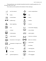
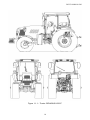
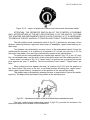
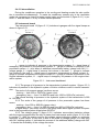
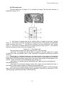
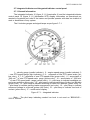
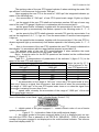
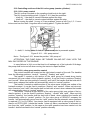
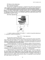
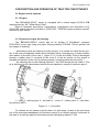
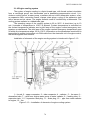
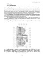
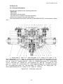
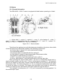
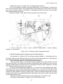
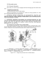
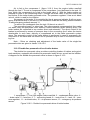
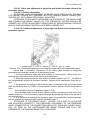
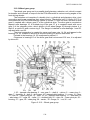
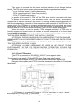
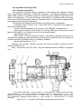
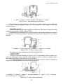
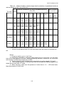
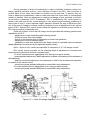
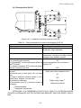
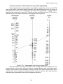
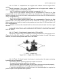
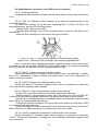
1
BELARUS
2022.5
2022.5-0000010 РЭ
OPERATOR'S MANUAL
2011
The operator's manual was composed by an engineer of the first Department of Constructive and Experimental Work, A.V. Runov, with participation of key specialists of DCEW-1 of
RUE “Minsk Tractor Works”
Publication responsible person – Y.M. Korotky, head of engineering office of design documentation of the DCEW-1.
Executive editor – A.G. Stasilevich, design manager of tractor production of PA “MTW”.
Editor-in-chief – I.N. Uss, PA “MTW” chief designer.
Operator's manual contains brief description and specifications of tractors Belarus 2022.5
produced by Minsk Tractor Works. The main tractors operating rules are set forth, the information about their adjustments and maintenance is provided.
Operator's manual is meant for tractor study, operation rules and servicing of tractors
“BELARUS-2022.5”.
In view of P/A “MTW” policy directed to constant upgrading of produced goods, the construction of some units and parts of Belarus tractor may undergo changes which are not
reflected in present edition. The detailed information may be obtained from “BELARUS”
dealer.
©
RUE ”Minsk Tractor Works”, 2009
All rights reserved. No part of this book may be reproduced in any form without written
permission of RUE “MTW”.
2022.5-0000010 OM
CONTENTS
1 TRACTOR DESCRIPTION AND OPERATION………………………………………… 13
1.1 Tractor assignment……………………………………………………………………… 13
1.2 Technical specifications ………………………………………………………………... 15
1.3 Tractor composition……………………………………………………………………… 18
1.4 Vibration level at operator's working place of tractor “BELARUS-2022.5”…………………. 20
1.5 Noise level at operator's working place of tractor “BELARUS-2022.5”……………….. 20
1.6 Tractor marking ………………………………………………………………………..... 21
1.7 Packing…………………………………………………………………………………… 21
2 CONTROLS AND INSTRUMENTS……………………………………………………… 22
2.1 Layout of controls and instruments of the tractor…………………………………….. 22
2.2 Switches of instrument board…………………………………………………………... 23
2.3 Upper shield unit of button switches ………………………………………………….. 26
2.4 Conditioner control………………………………………………………………………. 26
2.4.1 Conditioner control in conditioning mode…………………………………………… 26
2.4.2 Conditioner control in heating mode………………………………………………… 27
2.4.3 Cab ventilation…………………………………………………………………………. 28
2.5 Instrument board………………………………………………………………………… 28
2.6 Pilot lamps unit…………………………………………………………………………… 30
2.7 Integrated indicator and integrated indicator control panel…………………………. 31
2.7.1 General information…………………………………………………………………… 31
2.7.2 Assignment and operation principle of integrated indicator gauges …………….. 32
2.7.3 Pilot lamps of the integrated indicator………………………………………………. 35
2.7.4 Description of testing the integrated indicator performance………………………. 36
2.8 Information display………………………………………………………………………. 36
2.8.1 General information…………………………………………………………………… 36
2.8.2 Adjustment of brightness and sharpness of the information display…………….. 36
2.8.3 Call up of changeable images and parameters on the screen of the information
display ……………………………………………………………………………………...... 37
2.9 Engine control panel …………………………………………………………………….. 39
2.10 Steering…………………………………………………………………………………. 39
2.10.1 General information………………………………………………………………….. 39
2.10.2 Steering wheel adjustments ………………………………………………………... 40
2.11 Parking brake control……….................................................................................. 40
2.12 Pedals and handle for fuel feed manual control…………………………………….. 41
2.13 Switching of ranges, gears and passes of the gearbox reduction unit ……………………… 41
2.13.1 General information………………………………………………………………….. 41
2.13.2 Tractor velocity diagram …………………………………………………................ 42
2.14 Control panel for rear axle DL, FDA and FPTO drives. Rear power takeoff control……… 43
43
2.14.1 General information…………………………………………………………..
2.14.2 Indication of the engaged pass of the reduction unit…………………………….. 43
2.14.3 Front power take-off shaft control …………………………………………………. 44
2.14.4 FDA drive control…………………………………………………………………….. 44
2.14.5 Rear axle differential lock control………………………………………………….. 45
2.14.6 Annunciation of oil emergency temperature in the hydraulic lift linkage……….. 46
2.14.7 Rear PTO control ……………………………………………………………………. 46
2.15 Lift linkage controls ………………….……………………….................................... 47
2.15.1 General information on rules of rear lift linkage control………………………….. 47
2.15.2 RLL control panel……………………………………………………………………. 47
2.15.3 Remote buttons of RLL control system ………………………………….............. 50
2.15.4 Troubleshooting of RLL electronic control system……………………………….. 50
2.15.5 Front lift linkage control …………….………………………………………………. 51
2
2022.5-0000010 OM
2.16 Controlling sections of the HLL valve group (remote cylinders)…………………… 52
2.16.1 HLL pump control…………………………………………………………………… 52
2.16.2 HLL valve group section control…………………………………………………... 52
2.17 Cutout fuses…………………………………………………………………………… 53
2.17.1 Fuses for electrical equipment system…………………………………………… 54
2.17.2 Fuses of electronic control systems………………………………………………. 55
2.17.3 Fuses of engine electronic control system……………………………………….. 56
2.18 Switching unit………………………………………………………………………….. 57
2.19 Cab locks and handles……………………………………………………………….. 61
2.19.1 Cab door locks………………………………………………………………………. 61
2.19.2 Side glass opening…………………………………………………………………. 62
2.19.3 Rear screen opening……………………………………………………………….. 62
2.19.4 Cab hatch opening………………………………………………………………….. 62
2.20 Seat and its adjustments……………………………………………………………... 64
2.20.1 General information………………………………………………………………… 64
2.20.2 Seat adjustments…………………………………………………………………… 64
2.21 Controlling drive of transmission hydraulic system pump………………………… 65
2.22 Controlling pneumatic system compressor………………………………………… 65
2.23 Connector elements of the electrical equipment…………………………………... 66
2.23.1 Socket to connect coupled agricultural equipment……………………………………. 66
2.23.2 Connection of additional electrical equipment of coupled machines…………………. 66
3 DESCRIPTION AND OPERATION OF TRACTOR CONSTITUENTS……………... 68
3.1 Engine and its systems………………………………………………………………… 68
3.1.1 Engine…………………………………………………………………………………. 68
3.1.2 System of engine air cleaning………………………………………………………. 68
3.1.3 System of charged air cooling………………………………………………………. 69
3.1.4 Engine cooling system………………………………………………………………. 70
3.1.5 Exhaust system………………………………………………………………………. 71
3.2 Engine electronic control system……………………………………………………... 73
3.3 Coupling…………………………………………………………………………………. 78
3.3.1 Coupling clutch……………………………………………………………………….. 78
3.3.2 Peculiarities of clutch installation, dismantling and adjustment…………………… 79
3.3.2.1 General information………………………………………………………………... 79
3.3.2.2 Clutch dismantling…………………………………………………………………. 80
3.3.2.3 Clutch installation…………………………………………………………………... 80
3.3.2.4 Adjustment of clutch release levers………………………………………………. 80
3.3.3 Clutch drive…………………………………………………………………………… 80
3.3.4 Clutch control adjustment………………………………………………………….. 82
3.3.4.1 Clutch control adjustment………………………………………………………... 82
3.3.4.2 Bleeding of the hydraulic system of clutch control……………………………… 82
3.3.4.3 Clutch check for purity of disengagement……………………………………….. 83
3.3.5 Clutch case……………………………………………………………………………. 83
3.4 Gearbox…………………………………………………………………………………. 85
3.4.1 General information………………………………………………………………….. 85
3.4.2 Mechanism of engine start-up lock with range engaged and mechanism of
FDA disengagement when reversing…………………………………………………….. 89
3.4.3 Gearbox control mechanism………………………………………………………… 89
3.4.3.1 General information………………………………………………………………... 89
3.4.3.2 Speed shifting mechanism………………………………………………………... 89
3.4.3.3 Range shifting mechanism………………………………………………………... 90
3.4.3.4 Mechanism of switching between the higher and the lower passes of the
gearbox reduction unit……………………………………………………………………… 91
3.4.3.5 Gearbox control…………………………………………………………………….. 92
3.5 Reduction unit electro-hydraulic control…………………………………………….. 93
3
2022.5-0000010 OM
3.6 Rear axle…………………………………………………………………………………. 95
3.6.1 General information…………………………………………………………………… 95
3.6.2 Main drive………………………………………………………………………………. 96
3.6.3 Differential ……………………………………………………………………………... 96
3.6.4 Rear-axle drive………………………………………………………………………… 96
3.6.5 Final drive………………………………………………………………………………. 96
3.6.6 Rear axle final drive adjustment……………………………………………………... 97
3.6.7 Differential lock mechanism………………………………………………………….. 98
3.6.7.1 General information…………………………………………………………………. 98
3.6.7.2 Differential lock mechanism adjustment………………………………………….. 98
3.7 Rear power takeoff shaft………………………………………………………………... 99
3.7.1 General information…………………………………………………………………… 99
3.7.2 Rear PTO control……………………………………………………………………… 101
3.8 Front power takeoff shaft……………………………………………………………….. 102
3.9 Brakes…………………………………………………………………………………….. 104
3.9.1 General information…………………………………………………………………… 104
3.9.2 Service brake control………………………………………………………………….. 105
3.9.3 Service brake adjustment…………………………………………………………….. 106
3.9.4 Parking brake………………………………………………………………………….. 108
3.9.5 Parking brake adjustment…………………………………………………………….. 109
3.10 Pneumatic system…………………………………………………………………….... 110
3.10.1 General information………………………………………………………………….. 110
3.10.2 Single-line pneumatic drive of trailer brakes ……………………………………… 110
3.10.3 Double-line pneumatic drive of trailer brakes……………………………………... 111
3.10.4 Combined pneumatic drive of trailer brakes………………………………………. 112
3.10.4.1 General information………………………………………………………………... 112
3.10.4.2 Check and adjustment of single-line and double-line brake valves of the pneumatic system…………………………………………………………………………………….. 114
3.10.4.2.1 General information……………………………………………………………… 114
3.10.4.2.2 Check and adjustment of the single-line brake valve actuator of the
pneumatic system……………………………………………………………………………. 114
3.10.4.2.3 Check and adjustment of the double-line brake valve actuator of the
pneumatic system……………………………………………………………………………. 115
3.10.5 Check and adjustment of pneumatic system pressure regulator……………….. 116
3.11 Transmission hydraulic system……………………………………………………….. 117
3.12 Front driving axle……………………………………………………………………….. 119
3.12.1 General information………………………………………………………………….. 119
3.12.2 Central reduction unit………………………………………………………………... 119
3.12.3 Wheel gear group……………………………………………………………………. 120
3.12.4 Front driving axle drive………………………………………………………………. 121
3.12.4.1 General information………………………………………………………………... 121
3.12.4.2 Adjustment of FDA drive automatic switch……………………………………… 122
3.13 Electronic system for rear-axle differential lock control, front driving axle drive
control, front and power take off shaft control…………………………………………….. 123
3.13.1 Rear axle differential lock control…………………………………………………... 123
3.13.2 FDA drive control…………………………………………………………………….. 124
3.13.3 Front PTO control……………………………………………………………………. 125
3.14 Undercarriage and tractor wheels……………………………………………………. 126
3.15 Hydrostatic steering control…………………………………………………………… 127
3.15.1 General information………………………………………………………………….. 127
3.15.2 Dosing pump………………………………………………………………………….. 128
3.15.3 Steering hydraulic cylinder………………………………………………………….. 129
3.15.4 HSC oil tank…………………………………………………………………………... 130
4
2022.5-0000010 OM
3.16 Hydraulic lift linkage (HLL)…………………………………………………………….. 131
3.16.1 General information………………………………………………………………….. 131
3.16.2 Oil tank………………………………………………………………………………… 134
3.16.3 HLL pump drive………………………………………………………………………. 134
3.16.4 Valve group…………………………………………………………………………… 135
3.16.5 Installation and adjustments of position and force sensors of RLL ECS…………. 136
3.16.5.1 General information…………………………………………………………………. 136
3.16.5.2 Installation and adjustment of the position sensor……………………………... 136
3.16.5.3 Force sensor installation………………………………………………………….. 137
3.17 Indication of emergency states of hydraulic lift linkage……………………………. 138
3.18 Rear lift linkage…………………………………………………………………………. 139
3.18.1 General information………………………………………………………………….. 139
3.18.2 Turnbuckle……………………………………………………………………………. 139
3.18.3 Arm…………………………………………………………………………………….. 140
3.19 Rear lift linkage electronic control system…………………………………………… 141
3.20 Front lift linkage………………………………………………………………………… 143
3.20.1 General information………………………………………………………………….. 143
3.20.2 Rules of shifting FLL from operating position to transport position…………….. 143
3.20.3 Rules for coupling agricultural machines with FLL……………………………….. 144
3.21 All-purpose drawbar hitch……………………………………………………………... 145
3.22 Electrical equipment…………………………………………………………………… 146
3.22.1 General information………………………………………………………………….. 146
3.22.2 Heating plug operation principle……………………………………………………. 146
3.22.3 Order of integrated indicator programming………………………………………. 147
3.22.3.1 Control panel of integrated indicator……………………………………………. 147
3.22.3.2 Algorithm of integrated indicator programming………………………………... 147
3.22.4 Installation and adjustment of speed sensors and RPM sensor of rear PTO…. 149
3.22.4.1 Speed sensor installation………………………………………………………… 149
3.22.4.2 Installation of rear PTO RPM sensor……………………………………………. 149
3.23 Cab air conditioning and heating system…………………………………………… 150
3.24 Cab………………………………………………………………………………………. 153
3.24.1 General information………………………………………………………………….. 153
3.24.2 Cab installation……………………………………………………………………….. 153
3.24.3 Doors………………………………………………………………………………….. 154
3.24.4 Side screens………………………………………………………………………….. 155
3.24.5 Rear screen…………………………………………………………………………… 156
3.24.6 Outside mirrors……………………………………………………………………….. 157
3.24.7 Roof with opening hatch…………………………………………………………….. 157
3.25 Marking of tractor components……………………………………………………….. 159
4 INTENDED USE OF TRACTOR…………………………………………………………. 161
4.1 Safety measures to be taken preparing tractor for operation……………………….. 161
4.2 Tractor use……………………………………………………………………………….. 162
4.2.1 Boarding the tractor…………………………………………………………………… 162
4.2.2 Preparing for start and starting the engine………………………………………….. 162
4.2.3 Tractor motion start, GB shifting…………………………………………………….. 163
4.2.4 Tractor stop…………………………………………………………………………….. 165
4.2.5 Engine stop…………………………………………………………………………….. 165
4.2.6 Getting off the tractor………………………………………………………………….. 165
4.2.7 PTO use............................................................................................................... 165
4.2.8 Selection of optimal inner pressure in tires depending on operational conditions
and load on tractor axles, instructions for tire use………………………………………... 167
4.2.8.1 Selection of optimal inner pressure in tires depending on operational conditions and load on tractor axles……………………………………………………………… 167
4.2.8.2 Instructions for tire use……………………………………………………………… 171
5
2022.5-0000010 OM
4.2.8.3 Permissible combination of front and rear wheels……………………………….. 172
4.2.8.4 Tire inflation………………………………………………………………………….. 172
4.2.9 Rear wheel track formation…………………………………………………………… 173
4.2.10 Rear wheel twinning…………………………………………………………………. 174
4.2.11 Front wheel track formation…………………………………………………………. 175
4.3 Safety measures to be taken when operating the tractor…………………………… 177
4.3.1 General safety measures to be taken when operating the tractor……………….. 177
4.3.2 Fire safety measures………………………………………………………………….. 180
4.4 Tractor final assembly and run-in……………………………………………………… 181
4.4.1 Tractor final assembly………………………………………………………………… 181
4.4.2 Technical maintenance before tractor run-in……………………………………….. 181
4.4.3 Tractor run-in…………………………………………………………………………… 181
4.4.4 Technical maintenance during tractor run-in……………………………………….. 182
4.4.5 Technical maintenance after tractor run-in…………………………………………. 182
4.5 Actions in extreme conditions…………………………………………………………... 183
5 COUPLING OF IMPLEMENTS…………………………………………………………… 184
5.1 General information……………………………………………………………………… 184
5.2 Types of implements coupled with tractor “BELARUS-2022.5”…………………….. 186
5.3 Lift linkage………………………………………………………………………………… 187
5.3.1 General information…………………………………………………………………… 187
5.3.2 Three-point rear lift linkage…………………………………………………………… 187
5.3.3 Three-point front lift linkage………………………………………………………………. 191
5.4 Drawbar hitches………………………………………………………………………… 193
5.4.1 General information………………………………………………………………….. 193
5.4.2 Drawbar hitch DH-2V………………………………………………………………… 194
5.4.3 Drawbar hitch DH-ЗV………………………………………………………………… 195
5.4.4 Drawbar hitch DH-2R………………………………………………………………… 196
5.4.5 Drawbar hitch DH-1М-01…………………………………………………………….. 197
5.4.6 5 Drawbar hitch DH -1……………………………………………………………….. 198
5.5 Usage patterns of tractor hydraulic system for driving of operated parts and other
elements of unitized hydraulically operated machines and aggregates………………... 199
5.6. Selection of implements for coupling…………………………………………………. 201
5.6.1 General instructions…………………………………………………………………… 201
5.6.2 Methods of selection of the implements for coupling……………………………… 201
5.6.2.1 Calculating method for selection of implements for coupling……………………. 202
5.6.2.2 Experimental method for selection of implements for coupling………………….. 202
5.7 Test of correctness of composition of the machine and tractor unit………………... 205
5.8 Selection of ploughs…………………………………………………………………….. 206
5.9 Power take-off shaft ends………………………………………………………………. 207
5.10 Determination of PTO shaft and cardan shaft applicability………………………… 208
5.11 Features of application of PTO shafts and cardan shafts………………………….. 211
5.12 Ways of changing of drawbar features and passing ability of the tractors…………….. 215
5.12.1 General information……………………………………………………………………… 215
5.12.2 Ways of changing of drawbar features and passing ability of the tractors…………. 216
216
5.12.3 Application of hinge-mounted quick-detachable ballast
5.12.4 Filling up the tires with water (solution) for the purpose of adhesive weight
increasing…………………………………………………………………………………….. 216
5.12.5 Procedure of filling with water or water solution…………………………………. 218
5.12.6 Order of partial water or water solution drain from the wheels tires……………. 218
5.12.7 Order of full water or water solution drain from the wheels tires………………... 219
6
2022.5-0000010 OM
5.12.8 Selection of the tires internal pressure…………………………………………….. 219
5.12.9 Application of rear axis differential blocking………………………………………. 220
5.12.10 Doubling of wheels…………………………………………………………………. 220
5.13 Features of the tractor application in special conditions…………………………… 221
5.13.1 Tractor operation in areas with rugged topography. Possibility of the
tractor application for haylage allocation for reserve…………………………………….. 221
5.13.2 Application of substances for the purpose of chemical treatment………………. 221
5.13.3 Operation in a forest…………………………………………………………………. 221
5.13.4 Driving on public roads and selection of speed…………………………………… 222
5.14 Finding of total weight, loads on the front and rear axles, tires holding capacity
and required minimum ballast………………………………………………………………. 223
5.15 Choice and installation of front loader……………………………………………….. 225
5.15.1 General information………………………………………………………………….. 225
5.15.2 Safety measures at tractor “BELARUS-2022.5” operation with loader
installed……………………………………………………………………………………….. 227
5.15.3 Information about mounting holes………………………………………………….. 229
6 MAINTENANCE……………………………………………………………………………. 231
6.1 General instructions……………………………………………………………………... 231
6.2 Providing access to the components for maintenance services……………………………. 233
6.3 Maintenance procedure…………………………………………………………………. 234
6.4 Scheduled maintenance servicing operations………………………………………... 237
6.4.1 Maintenance on a shift basis (SBMS) in every 8 – 10 hours of operation
or per shift…………………………………………………………………………………….. 237
6.4.2 Maintenance services in every 125 hours of operation……………………………. 243
6.4.3 Maintenance services in every 250 hours of operation……………………………. 248
6.4.4 Maintenance services in every 500 hours of operation……………………………. 253
6.4.5 Maintenance service in every 1000 hours of operation…………………………… 258
6.4.6 Maintenance service in every 2000 hours of operation…………………………… 264
6.4.7 Maintenance service that is inconsistent with intervals of MS-1, 2MS-1, MS-2,
MS-3 and special MS………………………………………………………………………… 265
6.4.8 General maintenance services………………………………………………………. 266
6.5 Seasonal maintenance services……………………………………………………….. 268
6.6 Safety measures during maintenance and repair operations……………………….. 269
6.6.1 General safety requirements…………………………………………………………. 269
6.6.2 Safety precautions for exclusion of hazardous situations, related to an
accumulator battery and a fuel tank………………………………………………………... 269
6.6.3 Guidelines for safe use of leveling jacks and statement of places where they
shall be installed……………………………………………………………………………… 270
6.7 Filling and lubrication of the tractor with fuel and lubrication materials……………. 272
7. POSSIBLE FAILURES AND GUIDELINES FOR TROUBLESHOOTING…………... 276
7.1 Possible failures in clutch coupling and guidelines for troubleshooting……………. 276
7.2 Possible failures in gearbox and guidelines for troubleshooting……………………… 279
7.3 Possible failures in the electronic control system for rear axle differential
lock, front driving axle drive, front power take off shaft, GB reducing gear and
guidelines for troubleshooting………............................................................................. 280
7.4 Possible failures in rear axle and guidelines for troubleshooting…………………… 282
7.5 Possible failures in rear power take-off shaft and guidelines for troubleshooting… 283
7.6 Possible failures in front power take-off shaft and guidelines for troubleshooting... 284
7.7 Possible failures of brakes and guidelines for troubleshooting……………………... 285
7.8 Possible failures in pneumatic system and guidelines for troubleshooting………. 287
7
2022.5-0000010 OM
7.9 Possible failures of transmission hydraulic system and guidelines for troubleshooting……………………………………………………………………………………….. 290
7.10 Possible failures of FDA and guidelines for troubleshooting………………………. 291
7.11 Possible failures of hydrostatic steering control and guidelines for
Troubleshooting………………………………………………………………………………. 293
7.12 Possible failures in the electronic control system of RLL and guidelines for troubleshooting……………………………………………………………………………………. 297
7.13 Possible failures of the hydraulic lift linkage and guidelines for troubleshooting... 303
7.13.1 General information………………………………………………………………….. 303
7.13.2 guidelines for troubleshooting in HLL……………………………………………… 303
7.13.3 Section ЕНR-23LS lowering valve disassembly procedure……………………... 305
7.14 Possible failures in the electrical equipment and guidelines for troubleshooting... 307
7.14.1 General information………………………………………………………………….. 307
7.14.2 Search and elimination of failures in electrics power-supply system…………… 307
7.14.3 Search and elimination of failures in engine start-up system…………………… 309
7.14.4 Search and elimination of failures in lighting facilities……………………………… 310
7.14.5 Search and elimination of failures in air conditioner electrics…………………... 312
7.14.6 Search and elimination of failures in operation of front and rear wiper, windscreen washer, acoustic alarm……………………………………………………………… 313
7.14.7 Search and elimination of failures in operation of heating plugs………………... 313
7.14.8 Search and elimination of failures in engine management system……………... 313
7.14.9 Search and elimination of failures in test instruments located in
instrument board………………………………………………………………….................. 316
7.15 Possible failures of air-conditioning and cab heating systems and guidelines
for troubleshooting…………………………………………………………………………… 319
8. TRACTOR STORAGE……………………………………………………………………. 321
8.1 General instructions……………………………………………………………………... 321
8.2 Requirements for inter-shift storage of machines……………………………………. 321
8.3 Requirements for short-term tractors storage………………………………………… 321
8.4 Requirements for outdoors long-term storage………………………………………... 321
8.5 Preservation……………………………………………………………………………… 323
8.6 Depreservation and represervation……………………………………………………. 323
8.7 Putting tractor into operation after long-term storage………………………………... 323
8.8 Safety requirements for preservation………………………………………………….. 324
9. TRACTOR TRANSPORTATION AND TOWING………………………………………. 325
9.1 Tractor transportation……………………………………………………………………. 325
9.2 Towing of tractor…………………………………………………………………………. 325
10. TRACTOR DISPOSAL………………………………………………………………….. 326
SERVICE BULLETINS………………………………………………………………………. 327
ANNEX A (compulsory) - Electric circuit diagram of engine electronic control system
of “Belarus-2022.5” tractor………………………………………………………………….. 328
ANNEX B (compulsory) - Electrical circuit diagram of the DL, FDA and gearbox
reduction unit control system of “Belarus-2022.5” tractor………………………………... 329
ANNEX C (compulsory) - Electrical circuit diagram of electrical equipment
of “BELARUS-2022.5” tractor……………………………………………………………….. 330
8
2022.5-0000010 OM
Introduction
The present manual is designed for studying the structure, operation rules and
maintenance of tractors “BELARUS-2022.5”.
Scrutinize this manual and operation manual of the engine Д260 S3B – 0000100
РЭ, attached to your tractor. It will help you to study the rules of correct operation and
maintenance.
Failure to follow this instruction can lead to operator's injury or a breakdown of a
tractor.
Operation of a tractor, its maintenance and repair shall be carried out only by employees, familiar with all of its parameters and characteristics and informed about necessary safety requirements to prevent casualties.
In connection with constant development of the tractor some changes, which are
not depicted in the present manual, can be introduced in the structure of certain units and
parts.
Any arbitrary changes made by a consumer release the manufacturer from responsibility for possible further injuries to the operator and tractor breakdown.
Adopted abbreviations and conventional notations:
ADL – automatic differential lock;
AB – accumulator battery;
DL – differential lock;
RADL – rear axle differential lock;
PLU – pilot lamps unit;
SU – switching unit;
FB – fuse block;
FC – fast coupling;
ECU – engine control unit;
PTO – power takeoff shaft;
PRS – power reception shaft;
HSC – hydrostatic steering control;
HLL – hydraulic lift linkage;
HS – hydraulic system;
FFVS – frequency fuel volume sensor;
STM – shift-time maintenance;
RPTO – rear power takeoff shaft;
SPTA – spare parts, tools and accessories;
RA – rear axle;
RLL – rear lift linkage;
II – integrated indicator;
GB – gearbox;
CECS – complex electronic control system;
MTU – machine and tractor unit;
CC – coupling clutch;
LL – lift linkage;
IAH – inlet air heater;
FDA – front driving axle;
FPTO – front power takeoff;
VC – voltage converter;
FLL – front lift linkage;
FDAD – front driving axle drive;
9
2022.5-0000010 OM
CM – control module;
IICP – integrated indicator control module;
HPH – high pressure hoses;
HP – heating plugs;
SM – seasonal maintenance;
TCH – turbocharger;
MS – maintenance service;
MS1 – maintenance service No1;
MS2 – maintenance service No2;
MS3 – maintenance service No3;
DH –drawbar hitch;
ECS – electronic control system;
EECS – engine electronic control system;
EE – electrical equipment.
10
2022.5-0000010 OM
The manufacturer uses standard international symbols, regarding application of instruments and control units.
Given below are the symbols with indication of their meanings.
— see the manual ;
— control manipulations;
— brake;
— fast;
— manual brake;
— slowly;
— audible beep;
— forward;
— alarm signaling;
— reverse;
— fuel;
— accumulator charging;
— coolant;
— cab roof light;
— heating plugs;
— parking lights;
— engine speed;
— tractor turn indicator;
— oil pressure in the engine;
— trailer turn indicator;
— upper beam;
— temperature of engine coolant;
— low beam;
— off / stop;
— working lights;
— on / start;
— differential lock;
— gradual adjustment;
— PTO engaged;
11
2022.5-0000010 OM
— front screen wiper;
— front driving axle drive;
— rear screen wiper and
washer;
— fan;
— brake fluid level in main cylinder tanks;
— air filter clogged;
— oil pressure in HSC
— engine start;
— beacon
— road-train
— oil pressure in gearbox
— external cylinder – retracting
— braking of gearbox
— external cylinder – protracting
— air pressure in pneumatic
system
— external cylinder – floating
— swivel lever – up
— engine stop
— swivel lever – down
12
2022.5-0000010 OM
1 TRACTOR DESCRIPTION AND OPERATION
1.1 Tractor assignment
The tractor “BELARUS-2022.5” is intended for performance of various general –
purpose agricultural operations, for basic and preseeding treatment of soil, planting of
crops and other cultures in a structure with wide-span and combined units, for harvesting
operations in a structure with heavy-duty harvesting complexes that are designed for forage conservation, crop harvesting, for transport and loading operations.
The tractor “BELARUS-2022.5” is a general-purpose wheeled tractor of traction
class 3 with the wheel formula 4X4.
Appearance of the tractor “BELARUS-2022.5” is presented in figures 1.1.1.
13
2022.5-0000010 OM
Figure 1.1.1 – Tractor “BELARUS-2022.5”
14
2022.5-0000010 OM
1.2 Technical specifications
Main parameters and technical specifications of the chassis are given in table 1.1.
Table 1.1
Parameter
(characteristics) title
Parameter value for the tractor
“BELARUS-2022.5”
1 Traction class as per GOST 27021
2 Rated traction force, kN
3 Engine 1)
а) model
b) engine type 2)
3
30
Д-260.4 S3В
turbocharged with intercooling of the
charged air
six, in-line, vertical
7,12
c) number and position of cylinders 2)
d) displacement, l 2)
e) engine power, kW:
1) rated 2)
2) normal
f) crankshaft rated speed, rpm 2)
156,0±3,0
148,6±3,0
2100
g) specific fuel consumption at normal
power, g/(kW·h)
h) turning torque rated factor, % 2)
249
2)
i) max turning torque, N·m
4 Power on rear PTO in PTO mode
“1000 min-1”, kW, not less than:
5 Specific fuel consumption at power on
PTO in PTO mode “1000 min-1”, g/(kW·h),
not more than
6 Number of gears:
а) for forward travel
b) for backward travel
7 Tractor travel speed (design) at crankshaft rated speed, km/h:
а) for forward motion:
1) least creeping
2) highest traveling
b) for backward motion:
1) least
2) highest
8 Tractor weight, kg:
а) structural
b) operating
c) max. operating
d) ex-works 4)
15
30
923,0
130,4
247
24
12
1,86
39,70
2,60
18,40
6680±100
7220±100
10000 (11500 3))
6830
2022.5-0000010 OM
Table 1.1 continued
Parameter
(characteristics) title
Parameter value for the tractor
“BELARUS-2022.5”
9 Distribution of operating weight on axles, kg:
а) on front
b) on rear
10 Permitted load on axles, kN:
а) on front
b) on rear
11 Max weight of the trailer, kg
2890
4330
50
85
а) without brakes
b) with independent brake
c) with overrunning brake
d) equipped with a brake system (trailer
brakes are interconnected with tractor
brakes)
12 Clearance, mm, (on tyres of basic configuration) not less than:
а) under the rear axle body
3500
3500
12000
25000
540
410
b) under drawbar hitch bracket
13 Track dimensions (on tyres of basic
configuration), mm:
а) for front wheels
1620±20, 1725±20, 1790±20, 1890±20,
1940±20, 2040±20, 2105±20, 2205±20
b) for rear wheels
14 Least radius of turning circle (with
braking), m
15 Tractor base, mm
16 Crossed hindrances:
a) angle of climb without trailer, not less
than
b) angle of climb with trailer, not less
than
c) max fordable depth, m
17 Service life, years
18 Overall dimensions, mm:
а) length with rear lift linkage in transport
position
b) width on rear wheel axle shaft ends
1800±20 to 2010±20 and 2230±20 to 2500 ±20
5,3
2920±20
20º
12º
0,85
10
5230±50
2400±30
c) width on rear twinned wheels (on
tyres of basic configuration) with the preset
recommended track (1800 mm)
d) height to the top of cab
19 Tyres (basic configuration):
а) front wheels
b) rear wheels
16
3790±50
3120±30
420/70R24
580/70R42
2022.5-0000010 OM
Table 1.1 finished
Parameter
(characteristics) title
20 Electrical equipment as per GOST
3940:
а) rated supply voltage in on-board
power system, V
b) rated ignition voltage, V
21 Hydraulic system:
а) pump displacement under crankshaft
rated speed, l/min
b) safety valve operation pressure, MPa
c) conventional volume factor, not less
than
22 Working equipment:
а) rear power take-off shaft:
rated speed of PTO shaft end extension in the following modes, rpm:
- stage I 540/540Э (under 1929/1475 rpm
of engine crankshaft speed, respectively)
- II stage 1000/1000Э (under 1909/1460
rpm of engine crankshaft speed, respectively)
b) front power takeoff shaft:
rated speed of PTO shaft end extension
(under 2050 rpm of engine crankshaft), rpm
c) rear lift linkage:
1) loading capacity of rear lift linkage on
suspension axis, kg, not less than
2) time for raising rear lift linkage from
lowermost position into uppermost position
with test load on suspension axis, sec., not
more than
d) front lift linkage (against order):
e) drawbar hitch:
____________________________________
1)
Parameter value for the tractor
“BELARUS-2022.5”
12
24
53
20-2
0,75
540 (590/770 5))
1000 (1100/1460 5))
1000 (1025 5))
6500
6,5
In section 5 “Coupling of implements”
In section 5 “Coupling of implements”
Engine parameters, not specified in the table 1.1, shall meet 260 S3В – 0000100
РЭ document.
2)
For referential use.
3)
When operating in traction-drive mode and speed limit to 15 km/h.
4)
Specified depending on the configuration.
5)
At 2100 rpm of engine crankshaft speed.
17
2022.5-0000010 OM
1.3 Tractor composition
Tractor framework – semi-frame.
Undercarriage: front and rear driving wheels, with pneumatic tyres of low pressure.
Steering wheels are front wheels. The wheels are twinned by means of spacers.
The tractor is equipped with 4-stroke piston six-cylinder inner combustion engine with
in-line vertical arrangement of cylinders, with direct injection of diesel fuel and compression
ignition, corresponding to environmental requirements of Stage 3B.
System of engine lubrication is combined, some parts are lubricated under pressure, some – by spattering. The lubrication system consists of an oil sump, oil pump, liquid-oil heat exchanger, centrifugal oil filter and oil filter with paper filtering element.
The engine fuel supply system consists of the following parts:
- accumulator system of fuel supply Common RAIL, including a high-pressure fuel
pump, injectors, fuel accumulator under high pressure, sensors of engine working environment condition (pressure and temperature of fuel and air), electromagnetic actuating
mechanisms (fuel governor, electromagnetic injection valves), electronic unit of control and
communication check circuits, low-pressure pipelines, high-pressure pipelines;
- fuel fine filters;
- fuel coarse filters.
System of engine start-up is electric starter. A means of start-up facilitation under
low environmental temperatures is a heating plug.
System of air delivery consists of a turbocharger, an air pipeline and a system of
charged air cooling.
The turbocharger is executed as follows: radial centripetal turbine and centrifugal
single-stage compressor with cantilever arrangement of wheels in relation to supports.
The system of air purification consists of a dry-type air cleaner of “Donaldson” company FPG100318 with one paper filtering element P781039. This air cleaner has two stages
of purification.
Cooling system for charged air is of a radiator type. The CAC radiator is intended for
cooling the air, charged into the inlet collector.
System of engine cooling is closed-type with coolant compulsory circulation executed by a centrifugal pump. The water pump is driven by a V-belt from the crankshaft pulley. For acceleration of engine warming up after start-up and for automatic control of a
temperature mode at various loadings and ambient temperatures there are two thermostats ТС-107, mounted on the delivery line.
To provide for a required chemical composition of exhaust gases under Tier-IIIB
stage the system of selective catalytic reduction (SCR) is additionally installed in the exhaust system.
The coupling clutch is frictional, dry, two-disk, spring-loaded. The CC overlays are
ceramic-metal. The coupling control drive is hydrostatic with a hydraulic booster.
The gearbox is 24F + 12R, mechanical, fixed-ratio, with constant-mesh gears. Shifting of 6 gears within each of four ranges of front motion and two ranges of reverse is executed by means of synchro-mesh units, switching between ranges is executed by toothed
clutches and synchro-mesh units.
The rear axle:
- with the main drive as a pair of bevel gears with circular teeth;
- with final drives as a pair of cylindrical gears;
- with hub drives of a planetary type;
- with a differential with a mechanical lock, with electrohydraulic control.
18
2022.5-0000010 OM
Brakes:
Working brakes are multidisk, oil-lubricated, located on shafts of the driving gears of
the final drives. Working brakes control is interlocked with a pneumatic drive of trailer
brakes. The working brakes control drive is hydrostatic.
The parking brake is brought into coincidence with the working brakes, it has an independent manual mechanical control. The control is interlocked with the pneumatic drive
of trailer brakes.
The trailer brakes control drive is either single-wire pneumatic or double-wire
pneumatic, or combined pneumatic, interlocked with tractor brakes control.
The rear power takeoff shaft is continuous four-speed, with soft start-up, it has two
modes: basic and economy. The direction of rotation is clockwise when viewed from the
shaft end face.
The supply variant 1:
The tractor is equipped with the PTO shaft end extension 3 (20 splines) as per
GOST 3480,
The tractor set of spare parts, tools and accessories is completed with the PTO
shaft end extension 1c (8 splines) as per GOST 3480 and the PTO shaft end extension 2
(21 splines) as per GOST 3480 and ISO500.
The supply variant 2:
The tractor is equipped with the PTO shaft end extension 2 (21 splines) as per
GOST 3480 and ISO500
The tractor set of spare parts, tools and accessories is completed with the PTO
shaft end extension 1 (6 splines) as per ISO500 and the PTO shaft end extension 3 (20
splines) as per ISO500.
The front PTO (against order) is continuous, single-speed with a PTO shaft end extension of type 2 (21 teeth) under GOST 3480. The direction of rotation is clockwise when viewed
from the shaft end face.
The transmission hydraulic system provides for the following:
- switching of gearbox reduction unit passes, RPTO, FPTO and FDA drives, differential lock;
- filtration of transmission oil;
- pressure feed lubrication of gearbox bearings, planetary gear groups of the rear axle,
FDA support;
- clutch hydraulic booster operation.
Steering is hydrostatic. The feed pump is gear-type, the direction of rotation is left.
The dosing pump is gerotor-type. The type of the rotation mechanism - two hydraulic cylinders of bidirectional operation and a steering linkage.
The front driving axle is portal-frame, beam-type with planetary-cylindrical final
gears. The main drive is a pair of bevel gears with circular teeth. The differential is selflocked, with increased friction. The FDA is driven from the gearbox through the frictional
hydraulically-operated clutch and the crankshaft. The FDA control is electro-hydraulic.
The hydraulic lift linkage is remote-cylinder, providing for the draft, position and
combined adjustment of tillage depth of agricultural machinery, and suppression of vertical
oscillation of agricultural implements in traveling position; with electrohydraulic system
(HER) of rear lift linkage automatic control. The system has three pairs of independent outlets.
19
2022.5-0000010 OM
Free drain is available at the back of the tractor for operation with hydraulic units
with constant delivery, hydraulic motors for instance.
The rear lift linkage is a three-point linkage of category 3 under ISO 730 and a linkage 3 under GOST 10677. There are two cylinders 90x250.
The front lift linkage (against order) is a three-point linkage of category 2 under ISO
730 and a linkage 2 under GOST 10677. There are two cylinders There are two cylinders
Ts90x250
Drawbar hitches of a lift type:
- towing yoke DH 2V – for coupling with semi-trailers and semi-trailed implements;
- towing yoke DH 3V – for coupling with trailers and trailed implements;
- hydraulic hook DH-2 – for coupling with semi-trailers and semi-trailed machines
(against order);
- pin DH-2R (“Pithon”) – for coupling with semi-trailers and semi-trailed machines
(against order);
- towing bar DH-1M-01 –for coupling with semi-trailed and trailed agricultural machines;
- cross member DH-1 – for coupling with trailed and semi-trailed machines (against
order).
The cabin is a one-seated with a protective rigid framework, having thermal, noise
and vibration insulation, with a system of heating, air-conditioning and ventilation,
equipped with a sprung seat adjustable for operator's height and weight, with rear-view
mirrors, with a sun visor, with electrical wipers for front and rear screens, with front and
rear screen washers, with a roof lamp and a place to install a radio set. The cab doors
have got locks, there are keys for the left door. Upon request the tractor can be equipped
with an additional seat.
The electrical equipment complies with GOST 3940. The rated power supply voltage for on-board network is 12V. The rated voltage for the start-up is 24V.
Instruments are a combination of devices; these are an integrated indicator; informational display; pilot lamps (glow lamps and light emitting diodes), located on the block of
pilot lamps, on the control panel of the rear axle differential lock and FDA drive, on the engine control system board.
1.4 Vibration level at operator's working place of tractor “BELARUS-2022.5”
The vibration level at the operator's seat complies with the Council Directive
78/764/ЕEС. Values of the vibration level are given in the EU type approval for each type
of a seat.
1.5 Noise level at operator's working place of tractor “BELARUS-2022.5”
Noise level at the operator's workplace conforms to the Directive 2009/76/ЕС, Appendix 2, and does not exceed the value of 86 dB (A). External noise level conforms to Directive 2009/63/ЕС and does not exceed the value of 89 dB (A).
20
2022.5-0000010 OM
1.6 Tractor marking
1.6.1.
Metal nameplate is fixed at the rear of the cab on the right side, as shown in fig.
Additionally the tractor serial number is applied by means of percussion on the right
side member and duplicated on the right plate of the front ballast weight.
Nameplate on tractors supplied to the countries, not
being members of the EU
Figure 1.6.1 – Place of application the tractor nameplate
1.7 Packing
The tractor is dispatched to a consumer without packing.
21
Nameplate on tractors
supplied to EU countries
2022.5-0000010 OM
2 CONTROLS AND INSTRUMENTS
2.1 Layout of controls and instruments of the tractor
Controls and instruments, located in the tractor cab, are presented in fig. 2.1.1.
Figure 2.1.1 – Layout of controls and instruments of the tractor
22
2022.5-0000010 OM
To the figure 2.1.1 – Layout of controls and instruments of the tractor:
1 – sun visor; 2 – cab light with switch; 3 – place for radio receiver (car stereo) installation; 4 – conditioner control panel; 5 – upper shield unit of button switches; 6 – deflectors; 7
– recirculation shutters; 8 – supplementary switch of rear screen wiper; 9 – accumulator battery remote disconnect switch; 10 – starter and instruments switch; 11 – left multifunctional
underwheel switch; 12 – steering wheel; 13 – instrument board; 14 – pilot lamps unit; 15 –
integrated indicator; 16 – integrated indicator control panel; 17 – right multifunctional underwheel switch; 18 – emergency flashing switch; 19 – central light switch; 20 – switch of front
working lights mounted on front lights brackets; 21 – information display; 22 – handle to engage rear PTO drive; 23 – parking brake control lever; 24 – clutch control pedal; 25 – handle
for steering rake tilt fixation; 26 – left brake control pedal; 27 – right brake control pedal; 28 –
accelerator pedal; 29 – range shifting lever; 30 – lever to switch between gears and passes
of the reduction gear unit; 31 – rear lift linkage control console; 32 – console to control rear
axle DL and FDA drive; 33 – console of engine control system; 34 – handles to control the
hydraulic lift linkage valve group; 35 – rear PTO control lever; 36 – handle to control fuel
supply.
Notes – recirculation shutters are installed on “BELARUS – 2022.5” tractor upon request. When FPTO is installed upon request, pos. 32 – console to control rear axle DL,
drives of FDA and FPTO.
2.2 Switches of instrument board
1 – starter and instruments disconnect switch; 2 – left multifunctional underwheel
switch; 3 – right multifunctional underwheel switch; 4 – emergency flashing switch; 5 – central light switch; 6 – switch of front working lights mounted on front lights brackets; 7 – accumulator battery remote disconnect switch.
Figure 2.2.1 – Switches of instrument board
The starter and instruments disconnect switch 1 (see fig. 2.2.1) has four positions:
- «0» – off;
- «I» – instruments; pilot lamps unit, heating plugs are on;
- «II» – starter is on (non-fixed position);
- «III» – radio set is on.
The layout of positions of starter and instruments disconnect switch is given in fig.
2.2.2 and in informational plate of the switch.
23
2022.5-0000010 OM
Figure 2.2.2 – Layout of positions of starter and instruments disconnect switch
ATTENTION: THE REPEATED SWITCH-ON OF THE STARTER IS POSSIBLE
ONLY AFTER RETURN OF THE KEY INTO POSITION “0” OF THE SWITCH. TO TURN
THE STARTER AND INSTRUMENTS SWITCH INTO POSITION “III” IT IS NECESSARY
TO PRESS IN THE KEY WHEN IN “0” POSITION AND TURN IT CONTRACLOCKWISE!
The left multifunctional underwheel switch 2 (fig 2.2.1) provides for activation of turn
blinkers, switching between upper and lower beam of headlights, upper beam blinking, audible beep.
Turn blinkers are activated by moving a lever of the underwheel switch 2 from the
middle position forward (“a” is a right turn) or backward (“б” is a left turn) as in fig. 2.2.3. As
the tractor has made a turn the lever automatically returns to the initial position.
To switch on the road headlights set a central light switch 5 (fig. 2.2.1) into “III” position, as indicated below, and the lever of the underwheel switch into the middle position "в"
– "lower beam" according to fig 2.2.3. "Upper beam" is switched on by pushing the switch
lever against the stop (“г” position). The lever positions "lower beam" / "upper beam" are
fixed.
When pulling the lever against the stop (“д” position, fig 2.2.3) from the position of
the "lower beam" the lever is set into a non-fixed position activating the “upper beam”,
called “upper beam blinking”, irrespective of the position of the central light switch.
The audible beep is activated by pressing the lever in axial direction (axis of the switching lever). The beep can be activated in any position of the switching lever.
Fig 2.2.3 – Operational scheme of the left multifunctional underwheel switch
The right multifunctional underwheel switch 3 (fig.2.2.1) provides for activation of a
dual-speed wiper and a washer of the windscreen.
24
2022.5-0000010 OM
The windscreen wiper is activated by means of moving the underwheel switch lever
3 (fig. 2.2.1) from "off" position (“0” position according to fig. 2.2.4) into “a” position (first
speed) or (second speed). All positions are fixed.
The windscreen washer is activated (in a non-fixed position) by moving the switch
lever upward from any of three positions of the switch.
Figure 2.2.4 – Operational scheme of the right multifunctional underwheel switch
Pressing the emergency flashing button 4 (fig. 2.2.1) activates the emergency flashing. A pilot lamp, built in the button, flashes simultaneously with the emergency flashing
lights. Repeated pressing the button 4 deactivates the emergency flashing.
The central light switch 5 (fig.2.2.1) has three positions:
- position “I” – “off” (the upper part of the button is pressed as in fig 2.2.1);
- position ”II” – “front and rear parking lights, license plate lights, lighting of instruments on
the dashboard and also parking lights on a trailed machine are on” (middle position);
- position “III” – “all consumers of “II” position and road headlights are on” (lower part of
the button is pressed against the stop as in fig. 2.2.1).
When pressing the button of front working lights switch 6 (fig. 2.2.1) two front working lights, located on front light brackets, are actuated together with a light indicator, built in
the button.
Pressing the button (non-fixed position) of the accumulator battery remote disconnect switch 7 (fig. 2.2.1) the accumulator batteries are powered, the repeated pressing deactivates the accumulator batteries.
It is possible to activate and deactivate the accumulator battery by means of the accumulator battery manual switch 2 (figure 2.2.5) located in the area of the accumulator battery installation. To activate and deactivate the accumulator battery it is necessary to press
the button 1.
1 – button; 2 – AB manual disconnect switch; 3 – accumulator battery.
Figure 2.2.5 – Installation of the accumulator battery manual disconnect switch
25
2022.5-0000010 OM
2.3 Upper shield unit of button switches
Pressing the cut-out button 1 (fig 2.3.1) activates a flash beacon (if available).
Pressing the cut-out button 2 activates two front working lights, mounted on the cab
roof, and an indicating lamp, built in the button.
Pressing the cut-out button 3 activates two rear working lights (inner) and an indicating lamp, built in the button.
Pressing the cut-out button 4 activates two rear working lights (outer) and an indicating lamp, built in the button.
Pressing the cut-out button 5 activates the rear screen wiper or the wiper and the
washer of the rear screen simultaneously.
The cut-out button 5 has three positions:
- position “I” – “off”;
- position “II” – “rear screen wiper is on” – fixed position;
- position “III” – “rear screen wiper and rear screen washer are on simultaneously –
non-fixed.
During tractor operation on forward motion the cut-out switch 8 (fig. 2.1.1) shall be
in “on” position (i.e. in upper position).
Pressing the cut-out button 6 (fig. 2.3.1) activates “Road-train” signal lights and an
indicating lamp, built in the button (the “Road-train” lights are installed against order).
1 – flash beacon cut-out button; 2 – cut-out button of front working lights, mounted on
the cab roof; 3 – cut-out button of rear inner working lights; 4 – cut-out button of rear outer
working lights; 5 – cut-out button for rear screen wiper and washer; 6 – cut-out button of
“Road-train” signal lights.
Figure 2.3.1 – Upper shield unit of button switches
2.4 Conditioner control
2.4.1 Conditioner control in conditioning mode
The conditioner control unit 4 (figure 2.1.1) has switches 1 and 2 (figure 2.4.1).
1 – Switch for air flow adjustment;
2 – Conditioner cut-out switch and cooling capacity adjustment;
Figure 2.4.1 – Conditioner control unit
With the help of the switch 1 you can change air flow by changing fan speed. The
switch 2 allows to change temperature of cold and dry air outcoming from deflectors 6 (fig.
2.1.1) in the conditioning mode.
26
2022.5-0000010 OM
ATTENTION: THE AIR CONDITIONER CAN BE SWITCHED ON AND OPERATE
ONLY WITH THE ENGINE ON!
To switch on the conditioner it is required to do the following:
o turn the cut-out switch 2 (figure 2.4.1) clockwise to 180° until a blue scale begins;
o then turn the switch 1 to one of three marked positions (the fan rotor has three
kinds of rotation speed). After 3-5 minutes adjust a required temperature in the cab with
the switch 2;
o it is possible to adjust a mixture of outer air and recirculation air with recirculation shutters 7 (figure 2.1.1) if available;
To switch off the conditioner it is required to turn both switches 1 and 2 (figure 2.4.1)
contraclockwise into “0” position.
ATTENTION: MAKE SURE THE CONDITIONER IS SWITCHED OFF BEFORE
STOPPING THE ENGINE!
ATTENTION: WHEN THE CONDITIONER OPERATES IN THE COOLING MODE
MAKE SURE THAT THE HEATER CONTROL VALVE IS SHUT OFF IN ORDER TO
PREVENT THE SYSTEMS OF HEATING AND COOLING FROM SIMULTANEOUS OPERATION!
2.4.2 Conditioner control in heating mode
ATTENTION: REFILLING THE ENGINE COOLING SYSTEM SHALL BE CARRIED
OUT ONLY WITH LOW-FREEZING LIQUID SPECIFIED IN THE ENGINE OPERATIONAL
MANUAL!
To set the conditioner into the heating mode do the following:
- after refilling the cooling system with the cooling fluid start the engine and let the engine run at medium idle without opening the heater control valve to reach 70-80°C of cooling
system temperature;
- then open the heater control valve with a handle 2 (figure 2.4.2), to do this turn the
handle 2 contraclockwise against the stop;
- increase engine speed and let it run for one-two minutes until the heater radiator is
filled up with the fluid. Make sure the fluid circulates through the heater. The heater radiator must warm up. Herewith the cooling fluid level in the cooling system radiator will decrease;
- refill the cooling fluid through the filler of the expansion tank. Refill till the cooling
fluid level in the expansion tank reaches 50…60 mm below the upper edge of the filler;
- to warm up the cab quickly switch on the heater fan and open recirculation shutters;
ATTENTION: WHEN OPERATING IN THE HEATING MODE THE SWITCH 2 (FIGURE
2.4.1) SHALL BE COMPLETELY OFF TO PREVENT THE COOLING SYSTEM AND THE
HEATING SYSTEM FROM SIMULTANEOUS OPERATION!
1 – sun visor, 2 – handle of heater control valve; 3 – upper shield unit of button
switches.
Figure 2.4.2 – Installation of heater control valve
27
2022.5-0000010 OM
2.4.3 Cab ventilation
During the conditioner operation in the cooling and heating modes the cab ventilation is executed simultaneously. To make the conditioner operate only in the ventilation
mode it is necessary to close the heater control valve, set the switch 2 (figure 2.4.1.) in position “0” and the switch 1 in any of three marked positions.
2.5 Instrument board
The instrument board 13 (figure 2.1.1) includes six gauges with five signal lamps as
shown in figure 2.5.1.
Variant 1
Variant 2
1 – gauge to indicate oil pressure in the transmission system; 2 – signal lamp of
emergency air pressure in the pneumatic system; 3 – gauge to indicate air pressure in the
pneumatic system; 4 – pilot lamp of additional accumulator battery charge with 24V; 5 –
voltage gauge; 6 – signal lamp of reserve fuel volume in the tank; 7 – gauge to indicate
fuel volume in the tank; 8 – signal lamp of emergency temperature of engine coolant; 9 –
gauge to indicate temperature of engine coolant; 10 – gauge to indicate oil pressure in the
engine lubrication system; 11 – signal lamp of emergency oil pressure in the engine lubrication system;
Figure 2.5.1 – Instrument dashboard
2.5.1 The gauge of oil pressure in the transmission hydraulic system 1 (figure 2.5.1)
indicates oil pressure in the hydraulic system of friction clutches control in tractor transmission.
The scale of oil pressure gauge has three zones:
- working — from 800 to 1500 kPa (green color);
- emergency (two) — from 0 to 800 kPa and from 1500 to 1800 kPa (red color).
The normal working oil pressure in the hydraulic system of the transmission is 900
to 1100 kPa.
2.5.2 The scale of the gauge of oil pressure in the pneumatic system has three
zones:
- working – from 500 to 800 kPa (green color);
- emergency (two) — from 0 to 500 kPa and from 800 to 1000 kPa (red color).
A signal lamp 2 (red color) is built in the gauge scale which lights up when the pressure in the pneumatic system drops below 500 kPa.
2.5.3 The voltage gauge 5 (figure 2.5.1) indicates accumulator batteries voltage
with the engine stopped when the key of starter and instruments switch (figure 2.2.2) is set
in position “I”. With the engine running the voltage gauge indicates voltage on generator
terminals. A pilot lamp 4 of red color is built in the scale of voltage gauge. It is used only
with 24V starting system. It indicates the process of the additional battery charge with 24V
– it checks the workability of the voltage converter.
28
2022.5-0000010 OM
The states of the power supply system depending on the position of the gauge
pointer on the scale are given in table 2.1.
Table 2.1 – The states of the power supply system
Zone on the voltage gauge
States of power supply system
scale 5 (figure 2.5.1), color with the engine running
with the engine stopped
13,0 – 15,0 V
normal mode of charge
–
green
10,0 – 12,0 V
the generator is out of oraccumulator battery
red
der
discharged
12,0 – 13,0 V
No AB charge
AB has a normal charge
yellow
(low charging voltage)
15,0 – 16,0 V
AB recharge
–
red
white line in the yellow
Rated AB electromotive
zone
force is 12,7 V
ATTENTION: IF THE VOLTAGE GAUGE INDICATES ABSENSE OF AB CHARGE,
CHECK THE STATE AND TENSION OF THE GENERATOR DRIVE BELT!
2.5.4 The scale of the gauge indicating fuel volume in the tank 7 has the divisions
“0-1/4-1/2-3/4-1”. A signal lamp 6 (orange color) is built in the gauge scale, which lights up
when fuel volume in the tank drops below 1/8 of the total tank volume.
ATTENTION: DO NOT LET THE TANK BECOME EMPTY (THE GAUGE POINTER IS
IN THE ZONE OF ORANGE COLOR)!
2.5.5 The gauge of engine coolant temperature 9 reads data from the engine control
unit (ECU). The gauge scale has three zones:
- working – from 70 to 105 °С (green color);
- informational – from 40 to 70 °С (yellow color);
- emergency – from 105 to 120 °С (red color);
An emergency temperature lamp (red color) 8 is built in the scale, which operates in
two modes:
а) lights up and operates in a flashing mode with coolant values from 109 up to and
including 112 °С.
b) glows in a continuous mode with coolant temperature values from 113 °С and
higher.
2.5.6 The oil pressure gauge in the engine lubricating system 10 reads data from the
engine control unit (ECU). The gauge scale has three zones:
- working – from 100 to 500 kPa (green color);
- emergency (two) – 0 to 100 kPa and from 500 to 600 kPa (red color).
A signal lamp of emergency oil pressure drop 11 (red color) is built in the gauge
scale, which lights up when the pressure drops below 100 kPa.
ATTENTION: WHEN THE COLD ENGINE IS STARTED THE PRESSURE CAN BE
600 kPa and HIGHER!
ATTENTION: IF THE EMERGENCY PRESSURE LAMP IS ON WITH THE ENGINE
RUNNING, IMMEDIATELY STOP THE ENGINE AND ELIMINATE THE FAILURE!
29
2022.5-0000010 OM
2.6 Pilot lamps unit
The pilot lamps unit 14 (figure 2.1.1) includes five lamps. The allocation scheme is
presented in figure 2.6.1.
1 – pilot lamp to indicate that the air cleaner filter is clogged to the max. (orange
color); 2 – pilot lamp to indicate emergency oil pressure drop in the system of hydrostatic
power steering (red color); 3 – pilot lamp to indicate rear axle differential lock (orange
color); 4 – pilot lamp to indicate operation of heating plugs (orange color) 5 – pilot lamp to
indicate emergency brake fluid level (orange color).
Figure 2.6.1 – Pilot lamps unit
The operating principle of the pilot lamps of CLU is the following:
- pilot lamp 1 to indicate that the air filter is clogged to the max. (figure 2.6.1) lights
up when the max. permissible level of filter dirtiness is exceeded and the filter requires
cleaning;
- pilot lamp 2 to indicate emergency oil pressure drop in the system of hydrostatic
power steering lights up when the oil pressure in the system of hydrostatic power steering
drops below 0,08 MPa (periodic lighting up of the lamp 2 with engine minimal speed is assumed – when revolutions are increased the lamp will go out);
- pilot lamp 3 to indicate rear axle differential lock lights up when activating rear
axle differential lock;
- pilot lamp 4 to indicate emergency brake fluid lights up when brake fluid level in
the tanks of master brake cylinders is below the permissible level.
- pilot lamp of the heating plugs indicates heating plugs operation (functioning algorithm of the pilot lamp indicating heating plugs operation is provided in subsection 3.22.2
“Heating plugs operational principle” of this manual).
30
2022.5-0000010 OM
2.7 Integrated indicator and integrated indicator control panel
2.7.1 General information
The integrated indicator 15 (figure 2.1.1) (hereinafter II) and the integrated indicator
control panel 16 (figure 2.1.1) (hereinafter IICP) display information on operational parameters of systems and units of the tractor and provide operator with data on violation of
work or breakdown of any system.
The II includes gauges and signal lamps as per figure 2.7.1.
1 – velocity gauge (needle indicator); 2 – engine speed gauge (needle indicator); 3
– rear PTO speed gauge (light indicator); 4, 9 – segments of rear PTO speed scale (yellow color); 5, 7, 8 – segments of rear PTO speed scale (green color); 6 – annunciator of
“540 min-1” of rear PTO speed scale range (yellow color); 10 – annunciator of “1000 min1
” of rear PTO speed scale range (yellow color); 11 – pilot lamp to indicate headlights upper beam switching (blue color); 12 – pilot lamp to indicate switching of trailer turn blinkers
(green color); 13 – pilot lamp to indicate switching of tractor turn blinkers (green color); 14
– pilot lamp to indicate parking brake engagement (red color); 15 – pilot lamp to indicate
enhanced voltage in on-board system (red color); 16 – pilot lamp to indicate low level of
coolant (yellow color); 17 – multifunction display.
Figure 2.7.1 – Integrated indicator
Note – The pilot lamp indicating coolant low level is not used on “BELARUS –
2022.5” tractors.
31
2022.5-0000010 OM
The II control panel is presented in figure 2.7.2.
Figure 2.7.2 – The integrated indicator control panel
The control panel 16 (figure 2.1.1) allows to carry out manual programming with buttons «Параметр» (“Parameter”) and «Значение» (“Value”) (see figure 2.7.2), and also to
change the mode of showing data entered on the multifunctional display with «Режим»
(“Mode”) button. The “Режим” (“Mode”) button is also used to enter a non-fixed parameter
value when programming the device.
Rules on use of the IICP in the mode of displaying operational parameters and failure
messages on the multifunctional display are given below in subsection 2.7.2 “Assignment
and operation principle of II indicators”.
Rules on use of IICP in the II programming mode are given in subsection 3.22.3 “Integrated Indicator programming order”.
2.7.2 Assignment and operation principle of integrated indicator gauges
2.7.2.1 Velocity gauge 1 (figure 2.7.1) indicates a design speed of the tractor on a
needle indicator. The design speed exceeds the actual one, as tractor skidding is not
taken into account.
The velocity gauge 1 is actuated by signals coming from pulse sensors of rotation
frequency of toothed gears of final drives of right and left rear wheels. The speed is indicated in accordance with the signal from the sensor installed on the final drive gear of the
wheel, turning with a less speed.
In case one of the speed sensors is faulty the integrated indicator shows speed
readings in accordance with the signal coming from the correct sensor. Specific faults of
circuits or speed sensors when the signals from them are missing are displayed in the multifunctional indicator as “0” digit, characterizing the fault location – to the right or to the left
(see below).
2.7.2.2 The engine speed gauge 2 (figure 2.7.1) indicates rotation frequency of the
engine crankshaft on a needle indicator.
Information on engine speed comes from the electronic control unit. The range of
speed readings is from 0 to 3500 (rpm).
2.7.2.3 Rear PTO speed gauge 3 (figure 2.7.1) displays the rear PTO speed on a
light indicator.
The rear PTO speed gauge is actuated by signals coming from a pulse speed sensor, installed above the toothed washer of the rear PTO reduction unit.
Upon engaging the rear PTO in the mode of “540 min-1” the integrated indicator operates in the following way:
- the annunciator of “540 min-1” of rear PTO speed scale range 6 lights up;
- as the speed of the rear PTO shaft end extension reaches 320 min-1 a lower segment of the rear PTO gauge 9 lights up in combination with the annunciator 6.
- as the speed further increases, together with the annunciator 6 the rear PTO indicator segments light up successively from bottom upward in the following order: 8 – 7 – 5
– 4;
- then in the process of the rear PTO operation the rear PTO speed is displayed on
the indicator 3 in accordance with the upper lighting segment of the RPTO as per table 2.2.
32
2022.5-0000010 OM
The working order of the rear PTO speed indicator 6 when switching the mode “540
rpm efficient” is the same as for the mode “540 rpm”.
Upon engaging the rear PTO in the mode of “1000 rpm” the integrated indicator operates in the following way:
- the annunciator of “540 rpm” of rear PTO speed scale range 6 lights up (figure
2.7.1);
- as the speed of the rear PTO shaft end extension reaches 320 rpm a lower segment of the rear PTO gauge 9 lights up in combination with the annunciator 6.
- as the speed further increases, together with the annunciator 6 the rear PTO indicator segments light up successively from bottom upward in the following order: 8 – 7 – 5
– 4;
- as the speed of the RPTO shaft extension exceeds 750 rpm the annunciator 6 as
well as the segments 9, 8, 7, 5, 4 go out. Then the annunciator 10 and the lower segment
9 light up;
- as the speed further increases, together with the annunciator 10 the rear PTO indicator segments light up successively from bottom upward in the following order: 8 – 7 – 5
– 4;
- then in the process of the rear PTO operation the rear PTO speed is displayed on
the indicator 3 in accordance with the upper lighting segment as per table 2.2.
The working order of the rear PTO speed indicator 6 when switching the mode
“1000 rpm efficient” is the same as for the mode “1000 rpm”.
Note – A precise value for the RPTO speed can be checked on the multifunctional
display 17 (figure 2.7.1).
Table 2.2 – Correspondence of parameters of the indicator 3 (figure 2.7.1) to the
speed of the rear PTO end extension
Active annunciator of ranges of the rear PTO speed scale
Upper (as per fig. 2.7.1)
active segment of the
Annunciator 6 (figure 2.7.1)
Annunciator 10 (figure 2.7.1)
1)
rear PTO speed scale
“540 rpm”
“1000 rpm”
650
1150
4
580
1050
5
500
950
7
420
850
8
2)
320
750
9
___________________________________________________________________________________________________________
1)
the annunciator of the range of “540 rpm” of the rear PTO speed scale is actuated only if there is a signal from the sensor, and switches off when the annunciator of
the range of “1000 rpm” of the rear PTO speed scale turns on or when the signal from
the sensor is missing for more than 3 sec.
2)
speed value, whereby the annunciator of the range of “1000 rpm” of the rear
PTO speed scale turns on.
2.7.2.4 The multifunctional display 17 (figure 2.7.1) is a liquid-crystal display that
shows information in two fields 1 and 2 simultaneously (figure 2.7.3).
1 – digital symbol of the gear engaged; 2 – current numeric value of one of tractor
system parameters.
Figure 2.7.3 – Information fields of the multifunctional display
1 – the digital symbol of the gear engaged (digits 0 to 6) is displayed only on tractors with the CECS. Due to absence of the CECS on “BELARUS – 2022.5” tractors the
number of the gear engaged is not displayed on the multifunctional indicator. The informational field displays letter “A”.
33
2022.5-0000010 OM
The following parameters are displayed in the information field 2 (figure 2.7.3):
- total elapsed engine time;
- instant fuel flow;
- on-board voltage;
- remaining fuel volume;
- time of running with remaining fuel;
- rear PTO speed;
- testing workability of speed sensors;
- testing workability of frequency fuel volume sensor (FFVS);
- testing workability and connection of CAN-bus to the Integrated Indicator.
Switching between indication modes of “Total elapsed engine time “, “Instant fuel
flow”, “Remaining fuel volume”, “Time of running with remaining fuel”, “On-board voltage”,
“Rear PTO speed”, and switching between messages on faults are effected with “Mode”
button of the control panel (figure 2.7.2).
Samples of displaying operating parameters of the tractor on the multifunctional
display and their short description are given in table 2.3.
Table 2.3 – Samples of displaying operating parameters of the tractor on the multifunctional
display
Parameter
Sample of displaying
Parameter description
parameter on the multifunctional display
Total elapsed
engine time, h
The counter accumulates information on
the total elapsed engine time with uploading
a message “engine speed” from the engine
control unit and stores it when the power
supply is off. The range of engine time indications is from 0 to 99999 hours.
Instant fuel flow,
In this mode a current value of the instant
fuel flow with a resolution of 0,1 l/h is displayed.
On-board voltage, V
In this mode a current value of on-board
voltage with an accuracy of 0,1 V is displayed in a digital form.
Remaining fuel
volume in the
tank, l
In this mode a current fuel volume remaining in the tank is displayed in liters.
This mode is available only when the tractor is stopped (i.e. when there are no signals
from the speed sensors).
Time of running on remaining fuel, h
In this mode assessed engine time, calculated for current values of the instant fuel
flow and remaining fuel volume is displayed.
Rear
PTO
speed, rpm
In this mode a precise speed of the rear
PTO shaft end extension depending on the
signal from the rear PTO speed sensor is
displayed.
l/h
34
2022.5-0000010 OM
Samples of displaying fault messages on the multifunctional display and a short description of the tractor fault displayed are given in table 2.4.
Table 2.4 – Samples of displaying messages on tractor faults on the multifunctional display
Parameter tested
Testing workability and connection of speed sensors
Sample of fault displaying
on the Integrated Indicator
Fault description
In case there are no signals coming
from the speed sensor for 10-12 sec. a
message in the form of “0” digit is displayed on the multifunctional display
characterizing the location of the faulty
sensor (left or right) or breakage in the
circuit of the given sensor.
left
wheel
sensor
right
wheel
sensor
Testing workability of the frequency
fuel volume sensor
If there is no signal coming from the
frequency fuel volume sensor for two
sec. a message “FUEL” is displayed
on the screen.
Testing workability and connection of
CAN-bus to the Integrated Indicator with
CAN-interface
If there are no signals through CANbus of the integrated indicator a message “C-BUS” appears on the multifunctional display.
If the signal coming from the engine control unit is missing the respective indication
modes are switched off automatically and the message C-BUS appears in the information
field 2 of the multifunction display (figure 2.7.3).
Each of the abovestated fault messages is displayed in priority on the information
field 2 of the multifunctional display irrespective of the information currently displayed. With
sequential pushing the “Mode” button of the integrated indicator control module the messages shall be listed in turn. After the last message has been viewed and the “Mode” button has been repeatedly pressed the multifunctional display changes into displaying the
cyclic mode of the operating parameters specified before.
The fault messages are displayed on the LCD-screen every time the device is actuated until the cause is eliminated.
When the integrated indicator is powered-on the multifunctional display shows information in the indication mode which has been chosen before the moment of powering
off the integrated indicator.
2.7.3 Pilot lamps of the integrated indicator
The operating principle of pilot lamps on the integrated indicator is as follows:
- pilot lamp to indicate switching on the road lights upper beam 11 (figure 2.7.1)
lights up when switching on the upper beam;
- indicators of tractor turns and trailer turns 13 and 12 operate in a flashing mode
when actuated with the underwheel multifunctional switch 2 (figure 2.2.1) or when the
emergency button 4 is pushed in;
- pilot lamp to indicate the parking brake is enabled 14 (figure 2.7.1) operates in a
flashing mode with 1 Hz frequency when the parking brake sensor goes off;
- pilot lamp to indicate increased on-board voltage 15 gets activated when the tractor on-board supply voltage goes up above 19V and goes out when the voltage falls below
17V;
35
2022.5-0000010 OM
- pilot lamp to indicate low level of coolant. It is not used on “BELARUS – 2022.5”
tractors.
ATTENTION: WHEN THE TRACTOR ON-BOARD SUPPLY VOLTAGE GOES UP
ABOVE 19V THE INTEGRATED INDICATOR FULLY GOES OUT AND RECOVERES
WHEN THE ON-BOARD VOLTAGE FALLS BELOW 17V!
ATTENTION: PILOT SIGNALLING LAMS ARE ACTIVATED AND DEACTIVATED
SYNCHRONOUSLY WITH CHANGING THE STATE OF SYSTEM SENSORS!
2.7.4 Description of testing the integrated indicator performance
Each time the power supply is on, performance testing of needle pointers and scale
elements of the rear PTO indicator is carried out in the integrated indicator. Herewith the
indicator needle pointers move away from zero marks for one second (or the pointers flutter for not more than one second on indicator zero marks) and also both annunciators of
the rear PTO scale range 6 and 10 get actuated (figure 2.7.1) as well as all segments of
the rear PTO scale.
2.8 Information display
2.8.1 General information
The information display 21 (figure 2.1.1) is designed to display engine actual parameters and indication of the engine electronic control system (EECS) faults.
When the key of starter and instrument switch is set into “I” position (figure 2.2.2)
supply voltage is delivered to the engine electronic control system. After the supply voltage
is delivered the EECS constantly performs self-testing. If there are no faults in the EECS
operation, the information display functions in a working mode – it displays actual parameters of engine operation.
When the error is defined, the information display produces an acoustic signal and a
brief description of the identified errors appears on the screen, also a fault testing annunciator lights up or flashes on the engine control panel 33 (figure 2.1.1). Interpretation of error codes as well as recommended actions to be taken to eliminate the identified faults are
given in the engine operation book attached to your tractor.
ATTENTION: THE ERRORS IDENTIFIED ARE TO BE ELIMINATED! TO ELIMATE
THE ERRORS CONTACT YOUR DEALER!
2.8.2 Adjustment of brightness and sharpness of the information display
To enter the mode of adjustment of screen brightness and sharpness 7 (figure
2.8.2) press button 5. In the screen lower part images of buttons are given. Pressing button 1 decreases brightness, pressing button 2 increases brightness, pressing button 3 decreases sharpness, pressing button 4 increases sharpness, and pressing buttons 1,2,3,4
simultaneously adjusts to an average value of sharpness and max. brightness. Repeated
pressing button 5 exits the mode of brightness and sharpness adjustment.
36
2022.5-0000010 OM
2.8.3 Call up of changeable images and parameters on the screen of the information display
1 – button to activate the main (three-segment) image and choose between displayed parameters; 2 – button to activate four-section image and choose between displayed parameters; 3 – button to activate graphic display and choose between displayed
parameters; 4 – button to activate indication of error (fault) list and choose between displayed parameters; 5 – button to enter/exit the mode of adjustment of sharpness, brightness and configuration menu; 6 – changeable display of buttons functional purpose; 7 –
screen.
2.8.1 – Information display
Table 2.5 – Lift of parameters of four-segment and graphic indication of engine operation
Four-segment imag- Graphic imagParameters
Symbol
ing
ing
Electric voltage directly on terminals of
9
9
information monitor connection, V
Voltage on the terminals of the accumulator battery, measured by the
9
9
engine electronic control unit, V
Fuel flow
9
9
Engine oil temperature
9
9
Fuel temperature
9
Inlet air pressure
9
9
Engine oil pressure
9
9
Temperature of coolant in the engine
9
9
Air temperature at the inlet pipe
9
9
Accelerator position, %
9
Use of turning torque, rpm
9
Engine speed, rpm
9
37
9
2022.5-0000010 OM
The monitor buttons 1, 2, 3, 4, 5 (figure 2.8.1) are of multifunctional purpose. When
pushing any of the buttons 2, 3, 4 during the monitor operation, an image of the button
panel 6 appears on the screen, the icons denoting the current functions of each button.
Pressing the button 1 on the monitor activates the main three-segment image on the
screen. Hereby an engine speed scale is displayed in the upper left corner, and a scale of
oil pressure in the engine lubrication system in the upper right corner, cooling fluid temperature in the lower right corner, current fuel flow per hour in the lower left corner. When
the three-segment imaging is indicated the displayed parameters in the lower left corner
are chosen between with the button 1. To exit the mode of choosing between the displayed parameters in the upper right corner it is required to press button 5 after activation
of the button panel 6. After that the parameters are chosen between with the buttons 1 and
2.
After the button panel 6 has been called up a four-segment imaging of parameters
on the screen 7 is activated with the button 2. After the first pressing the button 2 four parameters are displayed in a digital mode on the screen:
- in the upper left corner – engine speed;
- in the upper right corner – coolant temperature;
- in the lower left corner – on-board voltage;
- in the lower right corner – oil pressure in the lubrication system.
When pressing the button 2 for the second and the third time, four parameters are
displayed on the screen in an analog from.
Using the mode of choosing between displayed parameters the customer can activate, if necessary, displaying of various engine parameters on the screen as per table 1.
The mode of parameter choosing is activated after calling up of the button panel with
short-time pressing the button 5. Sequential pressing the button 1 changes the parameters
displayed in the upper left corner, pressing the button 2 changes the parameters in the upper right corner, button 3 – in the lower left corner, button 4 – in the lower right corner. The
parameter choosing mode is exited with short-time pressing the button 5.
As the button panel has been called up pressing the button 3 activates graphical
displaying of parameters in the course of time (functions as parameter analogue recorder).
The required parameters are chosen with a sequential pressing the button 3 as per
table 2.5.
A temporary net can be adjusted in a configuration menu from 2, 10 or 30 min. to 1,
2, 4 or 8 hours. To enter the configuration menu it is necessary to press the button 5 for
more than 3 sec. Also it is possible to choose metric and British units of measurement in
this menu, among available languages it is possible to choose English, Spanish, Swedish,
French, German, Italian, Dutch, Portuguese and Russian.
ATTENTION: ONLY DEALERS ARE AUTHORISED TO CHANGE SETTINGS OF
CONFIGURATION MENU!
When errors (faults) are detected during operation the monitor produces a sound
signal and a rhombic flashing window with an exclamation mark appears on the screen.
After the button panel has been called up a list of active errors (faults) is invoked
with the button 4. Moving over the list is carried out with the button 1 and 2.
To exit displaying of the lift of active errors it is necessary to confirm reception of all
errors by pressing the button 3. After the errors stop to come into the display they are
automatically deleted from the list.
38
2022.5-0000010 OM
2.9 Engine control panel
The engine control panel is introduced in figure 2.9.1.
1 – button switch of testing activation, 2 – fault testing annunciator, 3 – testing jack,
4 – panel cover.
Figure 2.9.1 – Panel of engine control system
The button switch of testing activation 1 (figure 2.9.1) is intended to call up active
errors form the memory of the engine electronic control unit by means of light codes, displayed by the fault testing annunciator 2. This way of testing is alternative in comparison
with information display 21 (figure 2.1.1). Regarding reading and decoding light errors as
well as fault elimination refer to the engine operation manual, attached to your tractor. The
eliminated errors are to be eliminated. To eliminate the detected faults, please, contact
your dealer.
Five heater activation relays are located under the cover 4 from the side, as per figure 2.9.1.
After the key of the starter and instrument switch is turned from the position “Off” into the
position “Instruments are on”, the system is powered. After the system has been powered it
carries out a self-check. If there are no errors in the operation of the system the fault testing
annunciator 2 on the panel of engine control system shall turn on and go out, thus testifying of
workability of the annunciator 2 lamp and its correct connection to the tractor on-board system.
A special testing jack 3 is intended for connection of system testing devices KTS of
“BOSCH” company to carry out an extended service diagnostics of the engine under operation. The named system testing devices are recommended for dealer centers.
2.10 Steering
2.10.1 General information
“BELARUS-2022.5” tractors are equipped with hydrostatic steering control (HSC).
When the engine is stopped the HSC feed pump, driven by the engine crankshaft, does
not feed the hydraulic system of the HSC and it is automatically shifted to a manual mode,
which requires application of a greater effort on the steering wheel in order to turn the tractor.
39
2022.5-0000010 OM
2.10.2 Steering wheel adjustments
1 – steering wheel; 2 – chuck; 3 – handle to fix tilt of the steering column.
Figure 2.10.1 – Steering wheel adjustment
The steering wheel has the following adjustments:
- horizon tilt angle adjustment;
- height adjustment, along steering shaft axis.
To change height positioning of the steering wheel proceed as follows:
- unscrew the chuck 2 (figure 2.10.1) by 3-5 revolutions;
- set the wheel 1 to a position comfortable for work;
- screw in the chuck 2 with max. possible force of hand fingers.
The range of the steering wheel height adjustment is 100 mm, stepless.
To change the steering column tilt angle do the following:
- pull the handle 3.
- tilt the steering column to reach the position comfortable for work and releasing the
handle 3 swing the steering column smoothly in longitudinal direction until fixed firmly.
The steering column can be tilted and fixed in four positions from 25° to 40° with 5°
interval.
ATTENTION: HAVING FIXED THE STEERING COLUMN IN THE EXTREME
FRONT POSITION SET THE GEAR SWITCH LEVER OF THE GEARBOX TO A NEUTRAL POSITION, DISENGAGE GEARS OF THE GEARBOX (SET “0” GEAR), START
THE ENGINE AND WITH THE TRACTOR NOT MOVING MAKE SURE THE STEERING
CONTROL OPERATES WELL!
2.11 Parking brake control
Upper position of the lever 23 (figure 2.1.1) – parking brake “On”;
Lower position of the lever 23 – parking brake “Off”.
40
2022.5-0000010 OM
2.12 Pedals and handle for fuel feed manual control
2.12.1 Pressing the pedal 24 (figure 2.1.1) disengages the clutch.
2.12.2 Pressing the pedal 26 (figure 2.1.1) brakes the rear left wheel.
2.12.3 Pressing the pedal 27 (figure 2.1.1) brakes the rear right wheel. A joint plate
of the brake pedals is intended for simultaneous braking with the right and left brakes.
2.12.4 Pressing the pedal 28 (figure 2.1.1) increases the engine speed.
2.12.5 When the handle 36 (figure 2.1.1) is moved to the extreme front position, fuel is fed
to the max, when the handle is moved to the extreme rear position – fuel is fed to the min. in accordance with the minimum idle speed.
2.13 Switching of ranges, gears and passes of the gearbox reduction unit
2.13.1 General information
1 – lever to switch ranges of gearbox; 2 – lever to switch gears and passes of the gearbox reduction unit; 3 – diagram of switching gears and passes of the gearbox reduction unit; 4
– diagram of switching gearbox ranges; 5 – button to engage the lower (L) pass of the gearbox
reduction unit; 6 – button to engage the higher (H) pass of the gearbox reduction unit; 7 –
annunciator of the lower pass of the gearbox reduction unit (green color); 8 – annunciator
of the higher pass of the gearbox reduction unit (red color).
Figure 2.13.1 – Gearbox control
The required gear is set by means of the lever, shifting gears and passes of the
gearbox reduction unit 2 (figure 2.13.1) as per the scheme 3.
The required range is set by means of the range shifting lever 1 as per the scheme
4.
Pressing the button 5 or 6 on the handle for shifting gears and passes of the reduction unit 2 engages the lower or the upper pass of the gearbox reduction unit, respectively.
The annunciators 7 and 8 perform indication of the engaged pass of the reduction unit.
Engaging of passes “L” and “H” of the reduction unit is possible only when the gear
shifting lever 2 is set into “neutral” position.
41
2022.5-0000010 OM
2.13.2 Tractor velocity diagram
Figure 2.13.2 – “BELARUS-2022.5” tractor velocity diagram
The table of “BELARUS-2022.5” tractor velocity diagram (figure 2.13.2) on tyres of
basic configuration is attached to the cab right window.
42
2022.5-0000010 OM
2.14 Control panel for rear axle DL, FDA and FPTO drives. Rear power takeoff control.
2.14.1 General information
Elements of control panel of rear axle DL, FDA and FPTO drives (if available
against order) are introduced in figure 2.14.1.
1 – acoustic signal button; 2 – annunciator of FDA drive activation; 3 – switch of FDA
drive control; 4 – annunciator of rear axle DL engagement; 5 – switch of rear axle DL control; 6 – annunciator of engagement of the reduction unit higher pass; 7 – annunciator of engagement of the reduction unit lower pass; 8 – blank cover or annunciator of oil emergency
temperature in the tank of the hydraulic lift linkage; 9 – button to engage front PTO; 10 – annunciator of FPTO engagement; 11 – FPTO control switch.
Figure 2.14.1 – Control panel for rear axle DL, FDA and FPTO drives
2.14.2 Indication of the engaged pass of the reduction unit
After the engine has been started the lower pass of the reduction unit is engaged by
default – an annunciator 7 “turtle” (figure 2.14.1) lights up on the panel.
With the tractor stopped, pressing the button 6 (figure 2.13.1) on the lever handle engages the higher pass of the reduction unit. Hereby the annunciator 7 (figure 2.14.1) “turtle”
goes out and the annunciator 6 “hare” lights up.
With the tractor stopped pressing the lower button on the lever handle switches back
from the higher pass to the lower pass of the reduction unit. The annunciator 6 “hare” goes
out and the annunciator 7 “turtle” lights up on the panel.
Simultaneously with lighting up of the annunciators 7 and 6 corresponding annunciators on the lever of shifting gears and passes of the reduction unit light up.
IT IS FORBIDDEN TO SHIFT REDUCTION UNIT PASSES DURING TRACTOR
MOVEMENT!
43
2022.5-0000010 OM
2.14.3 Front power take-off shaft control
FPTO, if installed, is controlled with a switch 11 (figure 2.14.1) and a button 9. FPTO
engagement indication is performed by an annunciator 10.
In initial condition the FPTO drive is disengaged by default, the annunciator 10 does
not burn.
To engage the FPTO after the engine has been started it is required to set the switch
11 into position “Engaged” and press the button 9. After that the annunciator 10 will light up
confirming that the FPTO is in engaged condition.
To disengage the FPTO it is required to set the switch 11 into position “Disengaged”,
hereby the annunciator 10 will go out.
To engage the FPTO repeatedly, first it is required to set the switch 11 into position
“Engaged”, then press the button 9.
ATTENTION: AS THE ENGINE IS KILLED THE FRONT POWER TAKEOFF SHAFT
IS AUTOMATICALLY DISENGAGED. TO ENGAGE THE FPTO AFTER THE ENGINE IS
STARTED FOLLOW PROCEDURES ON THE FPTO ENGAGEMENT.
Note – Additional information on the FPTO operation rules is given in subsection
4.2.7 “PTO use”.
2.14.4 FDA drive control
The FDA drive is controlled with a switch 3 (figure 2.14.1). Indication of the FDA
drive operation is performed by an annunciator 2.
The switch 3 has three fixed positions:
- “FDA disengaged” – middle position;
- “FDA controlled automatically” – upper position;
- “FDA engaged positively” – lower position.
The mode “FDA disengaged” is used for traveling when moving on roads with hard
surface when the traveling speed is above 13 km/h in order to avoid increased wear of
front wheels.
In position “FDA automatic control” the FDA drive is automatically engaged when
the rear wheel skidding limit is exceeded and the tractor moves straightforward. The FDA
drive is disengaged automatically as the rear wheel skidding drops below the limit or the
guide wheels turn by more than 25 degrees to any side.
The annunciator 2 burns with the FDA drive engaged, and it goes out with the FDA
drive disengaged.
The mode “FDA automatic control” shall be used at various field works.
ATTENTION: IN THE MODE OF “FDA AUTOMATIC CONTROL” WITH REAR
WHEELS SKIDDING PREVENT FRONT WHEELS FROM TURNING AT ANGLES
CLOSE TO 25°, AS IN THIS CONDITION A CONSTANT ANTOMATIC ENGAGEMENT
AND DISENGAGEMENT OF FDA WILL TAKE PLACE, AND THIS CAN CREATE
ABRUPT DYNAMIC LOADS IN TRANSMISSION AND FDA DRIVE!
The mode of “FDA automatic control” is disengaged by setting the switch 3 into position
“FDA disengaged”. Herewith the annunciator 2 will go out.
If there is a necessity of FDAD positive engagement, irrespective of rear wheel
skidding, front wheel turning angle, it is required to set the switch 3 into position “FDA engaged positively”. The FDA drive is hereby permanently engaged and the annunciator 2 is
on. To disengage the positive mode set the switch 3 into position “FDA disengaged”, the
annunciator 2 will go out.
ATTENTION: OPERATING ON REVERSE USE ONLY POSITIVE ENGAGEMENT
OF FDA!
44
2022.5-0000010 OM
ATTENTION: USE ONLY POSITIVE ENGAGEMENT OF FDA WHEN OPERATING
THE TRACTOR UNDER BAD TYRE GRIPPING CONDITONS WHEN REAR WHEELS
SKID INCLUDING TRACTOR TURNING, TO INSURE SMOOTH ENGAGEMENT OF
FDA, FOR THIS DO THE FOLLOWING:
- STOP THE TRACTOR, HAVING DEPRESSED THE CLUTCH PEDAL;
- ENGAGE THE FDA IN THE MODE “FDA DRIVE ENGAGED POSITIVELY”,
HOLDING THE BUTTON 25 IN DEPRESSED CONDITION;
- SMOOTHLY RELEASE THE CLUTCH PEDAL.
ATTENTION: AUTOMATIC ENGAGEMENT OF FDA DRIVE, IRRESPECTIVE OF
THE SET MODE (INCLUDING THE MODE “FDA DISENGAGED”), TAKES PLACE WHEN
PRESSING THE INTERCONNECTED BRAKE PEDALS!
ATTENTION: WHEN OPERATING ON ROADS WITH HARD SURFACE IT IS
NECESSARY TO DISENGAGE THE FDA DRIVE IN ORDER TO PREVENT INCREASED
WEAR OF FRONT WHEEL TYRES!
ATTENTION: IN CASE WIRES IN CIRCUIT OF FDA DRIVE CONTROL ARE
BROKEN, AUTOMATIC ENGAGEMENT OF THE FRONT DRIVING AXLE TAKES
PLACE!
ATTENTION: VIOLATION OF RULES FOR USING FDA DRIVE OPERATION
MODES MAY RESULT IN BREAKDOWN OF FDA PARTS AND OTHER PARTS OF
TRANSMISSION!
IT IS FORBIDDEN TO OPERATE THE TRACTOR WITH FDA DRIVE ENGAGED
WHEN THE SPEED OF MOVEMENT IS ABOVE 13 KM/H!
2.14.5 Rear axle differential lock control
The rear axle differential lock (DL) is controlled with a switch 5 (figure 2.14.1). Indication of rear axle DL operation is performed by an annunciator 4.
The switch 5 has three positions:
- “DL disengaged: - middle non-fixed;
- “DL automatic control” – upper fixed;
- “DL engaged positively” – lower non-fixed.
To avoid increased wear of the rear wheel tyres and the rear axle differential use
the mode “DL engaged” when traveling on roads with hard surface with the travel speed
above 13 km/h.
The mode “DL automatic control” with guide wheel position corresponding to linear
movement, engages the rear axle DL and the annunciator 4 go off.
The real axle DL is disengaged automatically when the guide wheels turn to the angle above 13° or when any or both brake pedals are depressed. Herewith the annunciator
4 goes out.
The mode “DL automatic control” is disengaged by setting the switch 5 into position
“DL disengaged”. The annunciator 4 will go out.
Use the mode “DL automatic control” when carrying out operations with significant
relative skidding of rear wheels.
If there is a necessity of rear axle DL positive engagement for short time, irrespective of front wheel turning angle, it is required to push the switch 5 and hold it pressed in
position “DL engaged positively”. The rear axle DL remains engaged during holding the
switch 5 depressed. Simultaneously the annunciator 4 goes off. On releasing the switch 5
the RADL returns to its initial (disengaged) state and the annunciator 4 goes out.
IT IS FORBIDDEN TO OPERATE THE TRACTOR WITH RADL ENGAGED WHEN
THE SPEED OF MOVEMENT IS ABOVE 13 KM/H!
IT IS FORBIDDEN TO OPERATE THE TRACTOR WHEN TRAVELLING ON
ROADS WITH HARD SURFACE WITH RADL CONSTANTLY ENGAGED!
45
2022.5-0000010 OM
2.14.6 Annunciation of emergency oil temperature in the hydraulic lift linkage
“BELARUS – 2022.5” tractors manufactured since 2012 can have an annuncitor of
emergency oil temperature in the hydraulic lift linkage instead of the blind plug 8 (figure
2.14.1). The annuncitor of emergency oil temperature in the hydraulic lift linkage lights up
when oil temperature in the hydraulic lift linkage tank exceeds the permissible temperature.
2.14.7 Rear PTO control
The handle to engage the rear PTO drive 22 (figure 2.1.1) has two positions:
- upper position – “PTO drive engaged”;
- lower position – “PTO drive disengaged”.
The rear PTO control lever has two positions:
- shifting the lever 2 (figure 2.14.2) from the rear extreme position to the front extreme position engages the rear PTO;
- shifting the lever from the front extreme position to the rear extreme position disengages the rear PTO.
Note – The PTO control lever 2 in figure 2.14.2 is set into position “PTO disengaged”.
1 – instruction shield for rear PTO control; 2 – rear PTO control lever.
Figure 2.14.2 – Rear PTO control lever
The shaft for switching modes of the rear PTO drive 38 (figure 3.3.6) is located to
the left on the coupling clutch body under the HLL pump.
The rear PTO drive has two operation modes:
- standard – 540 and 1000 rpm;
- economy – 770 and 1460 rpm under engine rated speed.
Switching between the modes of the rear PTO (standard and economy) shall be
carried out only with the engine killed or with the engine min. speed. To do this it is required to loosen a fixing bolt 39 (figure 3.3.6) and turn the shaft 38 until engaged into the
clutch, after that tighten the fixing bolt. To engage the standard mode it is necessary to
turn the shaft contraclockwise against the stop, to engage the economy mode it is required
to turn the shaft clockwise against the stop.
Switching between the rear PTO speeds of 540 and 1000 rpm is carried out exclusively by installing the corresponding PTO shaft end extensions, that have respective
markings of “540” and “1000”. “BELARUS-2022.5” tractors do not have a special switch
between the speeds of 540 and 1000 rpm of the rear PTO.
Note – The RPTO operation is controlled over the integrated indicator, as specified
in subsection 2.7.2 – “Assignment and operation principle of the integrated indicator
gauges”.
Note – Additional information on the RPTO operation rules is given in subsections
4.2.7 “PTO use” and 5.9 “Power takeoff shaft ends”.
46
2022.5-0000010 OM
2.15 Lift linkage controls
2.15.1 General information on rules of rear lift linkage control
The RLL is controlled with the control panel 31 (figure 2.1.1) and remote buttons 4
and 5 (figure 2.15.3). If there are failures in RLL electronic-hydraulic control system a diagnostics annunciator 9 (figure 2.15.1) displays information on the failure and, if necessary, operation of RLL control system is blocked.
2.15.2 RLL control panel
RLL control panel, located on a side console in tractor cab, is presented in figure
2.15.1.
1 – handle to adjust speed of lowering; 2 – handle to select control method; 3 –
handle to adjust height limit of linkage uplifting; 4 – handle to adjust depth of soil tillage; 5
– annunciator of linkage uplifting (red color); 6 – annunciator of linkage lowering (green
color); 7 – handle to control RLL; 8 – retainer of blocking of RLL control handle; 9 – troubleshooting annunciator (red color); 10 – button to engage “dampening” mode; 11 – annunciator of “dampening” mode activation (orange color).
Figure 2.15.1 – RLL control panel
Order of RLL control is the following:
- set a method of control depending on operation character using the handle 2 (figure
2.15.1). Turning of handle clockwise against the stop – position method of control; contraclockwise against the stop – draft control, in between – combined control, the combined control is preferential;
- set a required height of implement uplifting in transport condition with the handle 3.
Turning the handle clockwise against the stop corresponds to max. uplifting, contraclockwise against the stop - to min. uplifting;
- set tillage depth with the handle 4. Turning the handle clockwise against the stop
corresponds to min. depth, contraclockwise up to “A” position corresponds to max depth;
turning of the handle contraclockwise against the stop corresponds to floating position;
- lower the linkage moving the handle 7 to a lower fixed position.
Then during operation it is required to adjust a trailed implement for optimal operation conditions:
- with the handle 2 – combination of control means;
- with the handle 4 – depth of soil tillage.
- with the handle 1 – speed of RLL lowering and uplifting. Turning of the handle
clockwise against the stop corresponds to the max. speed of lowering (uplifting), turning the
handle contraclockwise corresponds to min. speed lowering (uplifting).
47
2022.5-0000010 OM
The handle 7 has four positions:
а) middle position – disengaged;
b) upper position – uplift;
c) lower position – lowering (in operation – automatic control);
d) moving the handle downward (nonfixed) from “в” position – implement penetration (herewith the automatic control is off);
During RLL lowering or penetration the annunciator 6 turns on, and during uplifting
– the annunciator 5 turns on.
The system automatically limits a frequency of correction under draft control to an
average of 2 Hz. In case of intensive heating of oil in hydraulic system it is necessary to
reduce frequency of correction by moving the handle 2 towards the position method of
control and the handle 1 towards “turtle”. In a case of raising (“working out”) of the agricultural implement when moving over consolidated soil or ruts, deepen the implement by
pressing the handle 7 downwards. After releasing the handle 7 will come back to its fixed
position of "lowering". Thus the agricultural implement returns to the mode of the depth,
set up before by the handle 4. The implement is raised by moving the handle 7 into the
upper position.
When height adjustment of RLL is carried out during operation, the unnunciators 5
or 6 turn on.
ATTENTION: IN ORDER TO AVOID HLL PUMP FAILURE, IT IS FORBIDDEN TO
OPERATE THE TRACTOR IF ANNUNCIATOR 5 DOES NOT GO OUT AFTER THE IMPLEMENT WAS UPLIFTED!
ATTENTION: AT THE EMERGENCY STOP OF THE TRACTOR, IN ORDER TO
AVOID FURTHER PENETRATION OF THE AGRICULTURAL IMPLEMENT, SHIFT THE
HANDLE 7 INTO POSITION ”DISENGAGED”. AFTER STARTING TO MOVE SHIFT THE
HANDLE INTO POSITION “LOWERING” – THE IMPLEMENT WILL PENETRATE TO
DEPTH, SET UP BEFORE!
It Is required to know the following operation peculiarities of RLL control system:
- after the engine was started the diagnostics annunciator 9 lights up, indicating
workability and blocking of the control system;
- to unblock the system it is necessary to set the handle 7 into operating condition for
one time (uplift or lowering). Hereby the diagnostics annunciator 9 goes out.
- after the system is unblocked during first engagement automatic speed limitation
for the RLL uplift and lowering is provided for safety's sake. Moving the handle 7 into position “Disengaged” and then into position “Uplift” or “Lowering” removes the speed limitation.
Besides the functions described above the RLL electronic control system has a
mode “dampening” – suppression of oscillations of the agricultural implement in a transport
mode.
Turn on the “dampening” mode in the following order:
- set the handle 7 into “uplift” position – herewith the RLL lifts up to the top extreme
position and gets automatically deactivated;
- push the button “dampening” 10 – hereby the RLL moves form the top extreme
position down by 3% of the full RLL stroke and the annunciator of “dampening” activation
11 turns on;
- then to prevent accidental shifting of the handle 7 during transportation move the
blocking retainer 8 to the rotation axis of the handle 7. Hereby the handle 7 will be mechanically blocked in the upper position (“uplift”).
48
2022.5-0000010 OM
To turn off the “dampening” mode press the button 10. The annunciator of “dampening” deactivation will go out, and the RLL will return to its top position. Move the retainer 8
to its initial position.
ATTENTION: THE “DAMPENING” MODE IS ACTIVE ONLY WHEN THE HANDLE
7 IS IN THE “UPLIFT” POSITION!
ATTENTION: DURING FIELD WORKS (TILLAGE, CULTIVATION) THE “DAMPENING” MODE SHALL BE TURNED OFF!
Your tractor can be equipped with the RLL control console ПУ-03 manufactured by
“Izmeritel” plant and introduced in figure 2.15.2.
1 – handle to control the lift linkage (position 2 – uplift; position 3 – disengaged; position 4 – lowering (in operation – automatic control; position 5 – mode of implement deepening in case it raises (non-fixed)); 6 – detent to lock the lift linkage control handle; 7 –
handle to adjust depth of soil tillage; 8 – handle to adjust height limit of linkage uplifting; 9
– handle to select control method; 10 – handle to adjust speed of lowering; 11 – annunciator of linkage uplifting (red color); 12 – annunciator of linkage lowering (green color); 13 –
troubleshooting annunciator (red color); 14 – dampening button; 15 – dampening annuncitor (green color); 16 – RLL position indicator (green color, upper scale point – RLL in
max. raised position, lower scale point – RLL fully lowered).
Figure 2.15.2 – Rear lift linkage control console ПУ-03
Note – RLL position indicator 16 (figure 2.15.2) is not used on “BELARUS-2022.5”
tractors.
Rules on using the RLL control console ПУ-03 manufactured by “Izmeritel” plant are
similar to rules on use of the RLL control console produced by “BOSCH” company, introduced in figure 2.15.1.
49
2022.5-0000010 OM
2.15.3 Remote buttons of RLL control system
Remote buttons of RLL control are used as a rule for coupling agricultural implements and machines to the rear lift linkage.
Uplift and lowering of the rear lift linkage with the remote buttons on rear wheel
fenders can be carried out at different control modes – the handles 1, 2, 3, 4, 7 (figure
2.15.1) and similar handles of the RLL control console ПУ-03 can be left in any position, as
the system of control from inside the cab is hereby blocked.
To lift the RLL up, press any of the buttons 4 (figure 2.15.3) and hold it depressed.
To lower the RLL, press any of the buttons 5 and hold it depressed.
For safety's sake the control with the remote buttons is performed with interruption
of work. Pressing the uplift button 4 (lowering button 5) and holding it depressed lifts up
(lowers) the RLL for 5 sec., then it stops. For further uplifting (lowering) it is necessary to
press the corresponding button once again and hold it depressed!
Then after the implement has been attached, activation and work with HLL is performed in accordance with subsection 2.15.2.
WARNING: WHEN USING THE REMOTE BUTTONS OF RLL CONTROL DO NOT
STAND BETWEEN THE TRACTOR AND ATTACHED IMPLEMENT! TO PREVENT ACCIDENTS IT IS FORBIDDEN TO USE BUTTONS OF MECHANICAL SHIFTING OF
ELECTRIC VALVES OF REGULATOR EHR23-LS!
1 – RLL remote control console; 2 – shield on safety regulations; 3 – shield on RLL
control diagram; 4 – RLL uplift button; 5 – RLL lowering button.
Figure 2.15.3 – RLL controlled with remote buttons
2.15.4 Troubleshooting of RLL electronic control system
The electronic control system, installed on your tractor, has an option of self-testing
and whenever failures are detected it provides the operator with code information by
means of a troubleshooting annunciator 9 (figure 2.15.1) on RLL control console. After engine start, as specified in subsection 2.14.2, the annunciator 9 is burning continuously if no
failures are detected in RLL control system. Moving the handle 7 up or down deactivates
the annunciator 9.
In case failures are detected in the system after the engine start, the annunciator 9
begins to show code information of the failure. If necessary the system gets blocked.
The failure code is displayed as a two-digit number, where the first digit is equal to
the number of flashings of the annunciator 9 after the first long pause, and the second digit
50
2022.5-0000010 OM
is equal to the number of flashings after the second long pause. For example, the operation algorithm of the annunciator 9 is the following:
- engine start;
- continuous glowing;
- after the system is unblocked the annunciator goes out;
- three-time flashing of the annunciator;
- long pause (glow missing);
- six-time flashing of the annunciator.
- long pause (glow missing).
It means that the system has a failure with a code “36”. If several failures are detected simultaneously the system indicates failure codes one after another dividing them
with a long pause.
All failures are divided by the system into three groups: complex, medium and light.
If complex failures are detected the control is stopped and the system gets deactivated. The system is not controlled either with the control panel or with the remote buttons.
The troubleshooting annunciator shows a failure code. After the failure has been eliminated and the engine started the system recovers.
With medium failures the control is stopped and the system gets blocked. The system is controlled only with the remote buttons and is not controlled from the main console.
The troubleshooting annunciator shows a failure code. After the failure has been eliminated and the engine started the system recovers.
With light faults the troubleshooting annunciator shows a fault code, but the system
remains controlled and is not blocked. In case of light faults the RLL control system operates improperly – there is no correct soil sensing. After the fault has been eliminated the
troubleshooting annunciator turns off.
In case the system detects a failure relating to any group of complexity the following
actions shall be taken:
o read the code;
o stop the engine;
o eliminate the failure in accordance with instructions of subsection 7.2 “Possible
failures in electronic control systems of RLL and guidelines for troubleshooting”;
o start the engine and if there are no faults get down to work.
If the RLL control console ПУ-03 manufactured by “Izmeritel” plant is installed (troubleshooting annunciator 13 (figure 2.15.2), RLL control handle 1) troubleshooting of the
RLL electronic control system is the same.
2.15.5 Front lift linkage control
The front lift linkage, installed upon request, is controlled by a handle 2 and 3 (figure
2.16.2) that in their turn control the second and the third sections of the hydraulic valve
group, respectively.
Note – Connection of the FLL control to the first section of the hydraulic valve
group, having the fixed position “uplift”, is not reasonable, as this section is intended to
control the hydraulic units of coupled machines having a hydraulic drive with permanent oil
circulation (hydraulic motor).
51
2022.5-0000010 OM
2.16 Controlling sections of the HLL valve group (remote cylinders).
2.16.1 HLL pump control
The HLL pump is located on the coupling clutch body to the right.
The HLL pump switching shaft 1 (figure 2.16.1) has two positions:
- “shaft on” – the shaft is turned clockwise against the stop;
- “shaft off” – the shaft is turned contraclockwise against the stop.
Before turning the shaft 1 to any of 2 two positions, loosen a bolt 3 by 1,5…2 revolutions and turn the shaft 1 together with a locking plate 2. Tighten the bolt 3.
1 – shaft; 2 – locking plate; 3 – bolt; 4 – pressure adjustor in pneumatic system.
Figure 2.16.1 – HLL pump control
Note – The figure 2.16.1 shows the position “HLL pump on”.
ATTENTION: THE PUMP SHALL BE TURNED ON AND OFF ONLY WITH THE
MIN. IDLE SPEED OF THE ENGINE!
In case failures in HLL occur that lead to oil leakage out of the hydraulic lift linkage,
the pump shall be turned off when moving the tractor to repair facilities.
2.16.2 HLL valve group section control
The control handles are located on the right lateral console of the cab. The handles
have the following positions: “neutral”, “lowering”, “floating” and “uplift”.
The handle 3 controls a left section of the valve group as viewed along tractor
movement (left rear outlets of the hydraulic system). It can be fixed in positions “floating”
and “neutral”. When set into positions “lowering” and “uplift” the handle shall be held with a
hand, when released the handle will automatically return to “neutral” position.
The handle 2 controls a middle section of the valve group (middle rear outlets of the
hydraulic system). It can be fixed in positions “floating” and “neutral”. When set into positions “lowering” and “uplift” the handle shall be held with a hand, when released the handle
will automatically return to “neutral” position.
The handle 1 controls a right section of the valve group (right rear outlets of the hydraulic system). It can be fixed in positions “floating”, “neutral” and “uplift”. When set into
position “lowering” the handle shall be held with a hand, when released the handle will
automatically return to “neutral” position. For the valve group of “BOSCH” company the
handle 1 will automatically return from the “uplift” position as the automatic return pressure
is reached (17,5 to 19,5 MPa). Your tractor can be equipped with a valve group of the hydraulic unit РП70-1523.1 where the handle 1 does not have a mechanism of automatic return from the “uplift” position. In this case as the uplift operation has been carried out, the
handle 1 shall be returned to the “neutral” position manually.
52
2022.5-0000010 OM
1, 2, 3 – handles to control HLL valve group sections; 4 – instruction shield with diagram of HLL valve group section control.
Figure 2.16.2 – HLL valve group section control
Instruction shield with a diagram of HLL valve group outlets connection to outer
consumers is attached to the tractor valve group as per figure 2.16.3. The valve group outlets are equipped with fast couplings with color protective covers: red – uplift, green – lowering.
Figure 2.16.3 – Diagram of HLL valve group outlets connection to outer consumers
2.17 Cutout fuses
WARNING: TO AVOID BURNING OF TRACTOR WIRING NEVER USE FUSES
WITH CURRENT RATING HIGHER THAN RATING SPECIFIED IN THIS SECTION. IF A
FUSE OFTEN BURNS OUT, FIND OUT THE CAUSE AND ELIMINATE THE FAULT!
53
2022.5-0000010 OM
2.17.1 Fuses for electrical equipment system
Cutout fuses are intended for protection of electrical lines against overloads and
short circuit.
Fuses, located in the battery compartment on the front hood frame to the right as viewed
along tractor movement (before the radiator unit), are introduced in fig. 2.17.1.
1 – accumulator battery, 2 – front hood frame, 3 – fuse block блок, 4 – 80 A fuse of tractor board power supply, 5 – 60 A fuse of EECS power supply; 6 – bracket to attach fuse block.
Figure 2.17.1 – Installation of fuses located in the battery compartment on the front
hood frame.
Fuse of voltage converter (VC) 3 (figure 2.17.2) is built in the VC body.
1 – voltage converter fixture; 2 – voltage converter; 3 – 20 A fuse of voltage converter
Figure 2.17.2 – Installation of fuse of voltage converter
Location of voltage converter is provided in figure 3.17.3.
1 – voltage converter; 2 – AB manual disconnect switch; 3 – accumulator battery.
Figure 2.17.3 – Voltage converter installation
54
2022.5-0000010 OM
The other fuses of electrical equipment system are mounted in the switching unit.
Assignment, places of location and ratings of fuses, included into the switching unit, are
given in subsection 2.18 “Switching unit”.
2.17.2 Fuses of electronic control systems
To get access to cutout fuses of electronic control systems (ECS) remove a screw 3
(figure 2.17.4) on a cover 2 of the side console 1 and open the cover.
1 – side console; 2 – cover; 3 – screw.
Figure 2.17.4 – Location of fuses of ECS
Fuses of electronic systems controlling DL, FDA, gearbox reduction unit, FPTO (if
available) and RLL are provided in figure 2.17.5.
Figure 2.17.5 – Fuses of electronic control systems
Five cutout fuses (figure 2.17.5) protect the following electrical circuits from overloads:
1 – FDA drive control (7,5 А);
2 – Rear axle DL control (7,5 А);
3 – FPTO control (7,5 А);
4 – RLL control (7,5 А);
5 – Gearbox reduction unit control (15 А);
6 – Reserve (7,5 А).
55
2022.5-0000010 OM
2.17.3 Fuses of engine electronic control system
Location of 60A fuse of EECS power supply is given in figure 2.17.1.
Location of a fuse block of SCR system heaters is given in figure 3.2.6.
A 30A fuse 5 (figure 2.17.6) protects “-“ of electrical circuit of urea (delivery, drain,
intake) and feed module pipes.
A 30A fuse 2 protects “+“ of electrical circuit of urea (delivery, drain, intake) and
feed module pipes.
Fuses 3 and 4 are reserve, currently not used.
1 – heater fuse block; 2 – fuse for “+“ of electrical circuit of urea and feed module
pipes; 3, 4 – reserve fuse; 5 – fuse for “– “ of electrical circuit of urea and feed module
pipes.
Figure 2.17.6 – Fuses of SCR system heaters
56
2022.5-0000010 OM
2.18 Switching unit
The switching unit 3 (figure 2.18.1) is intended for current supply, its distribution between tractor power consumers and for protection of electrical lines against short-circuit
and current load excess.
Your tractor may be equipped with two types of switching units – БКА-7.3722 or БК1, which are interchangeable.
Place of the switching unit installation is in the cab, on a metal beam of plastic shell
fixation, between a dashboard 4 and a windscreen.
To access relay and fuses of the unit 3 it is needed to unscrew two quick detachable screws 1, then remove a plastic cover 2. The unit also has a plastic protective cover,
intended for dust protection.
1 – screw; 2 – cover; 3 – switching unit; 4 – dashboard.
Figure 2.18.1 – Switching unit installation
The unit consists of thirty cutout fuses 1 (figure 2.18.2) (FU1-FU30) and nineteen
electromagnetic relays 4 (K1-K19), commutating current supply for consumers, a set of
spare fuses 5. Signal led lamps of red color 2, located on the front board near each fuse,
are intended for indication of a corresponding fuse blow out. A signal led lamp of green
color 3 indicates turning on of the switching unit.
а) БКА-7.3722
57
2022.5-0000010 OM
b) БК-1
1 – cutout fuse; 2 – signal led lamp of red color; 3 – signal led lamp of green color; 4
– electromagnetic relay; 5 – set of spare fuses.
Figure 2.18.2 – Switching unit
Note – The signal led lamp of green color 4 may not be installed in the switching
unit БК-1.
Diagram of fuses and relay location in the switching unit is introduced in figure
2.18.3.
а) Diagram of fuses and relay location in БКА-7.3722
b) Diagram of fuses and relay location in БК-1
Figure 2.18.3 – Diagram of fuses and relay location in the switching unit
58
2022.5-0000010 OM
Tables of fuses and relay assignment, presented in figure 2.18.3, are stuck from inside to the
upper plastic cover 2 (figure 2.18.1) from the windscreen side.
Information on fuses and relay assignment as well as fuse ratings is given in tables
2.6 and 2.7.
Table 2.6 – Assignment of switching unit fuses
Fuse designation
FU1
FU2
FU3
FU4
FU5
FU6
FU7
FU8
FU9
FU10
FU11
FU12
FU13
FU14
FU15
FU16
FU17
FU18
FU19
FU20
FU21
FU22
FU23
FU24
FU25
FU26
FU27
FU28
FU29
FU30
Fuse assignment
(protected electric circuit)
Fuse rating
Reserve
Lower beam of right road headlight
Lower beam of left road headlight
Road headlights upper beam
Reserve
Rear screen washer and wiper
Power supply to conditioner electric motor
“Road-train” lights and cab light
Signal beacon
Rear working lights (a pair of outer lights)
Front working lights (on the roof)
Not used
Not used
Rear working lights (a pair of inner lights)
Radioset (stereo-recorder)
Horn
Front working lamps (on handgrip)
Braking lights
Socket to connect trailed agricultural equipment and
a portable lamp.
Signal from terminal “D” of the alternator to RLL
control system
Front screen washer and wiper
Warning indication
Power supply to consumers, staying on when the
starter and instrument switch is in position “instruments are on”
Left parking lights
Right parking lights and instruments illumination
EECS, gearbox reduction unit control
Test instruments, sensors of speed, PTO and fuel
volume
Annunciation of tractor and trailer turning
Remote disconnect switch of accumulator battery
Power supply to coil of instrument illumination and
parking lights relay
20А
7,5А
7,5А
15А
20А
15А
25А
7,5А
7,5А
15А
15А
15А
30А
15А
15А
15А
15А
15А
59
15А
30А
15А
15А
25А
7,5А
15А
15А
7,5А
7,5А
15А
20А
2022.5-0000010 OM
Table 2.7 – Relay assignment
Relay designation
К1
К2
К3
К4
К5
К6
К7
К8
К9
К10
К11
К12
К13
К14
К15
К16
К17
К18
К19
Relay assignament
Radioset (stereo-recorder)
Rear working lights (a pair of inner lights)
Conditioner
Rear working lights (a pair of outer lights)
Front working lights (on the roof)
Not used
Not used
Heating plug control unit
Starter
Horn
Front working lamps (on handgrip)
Tractor turning indication and emergency indication
Signal from terminal “D” of the alternator to systems of RLL control
Power supply to consumers, staying on when the starter and instrument switch is in position “instruments are on”
Lock of AB remote disconnect switch
Road headlights lower beam
Road headlights upper beam
Parking lights and instrument illumination
Starter startup lock with gearbox range engaged
Note – Fuse and relay designation on the switching unit corresponds to fuse and relay designation on tractor electrical diagram in annex C.
A set of spare fuses 5 (figure 2.18.2), installed on the front panel of the switching
unit, includes spare fuses 2 (figure 2.18.4) with 7,5А, 15А, 20А, 25А, 30А ratings and, for
БКА-7.3722, a fuse removal tool 1. БК-1 is not completed with the fuse removal tool.
1 – fuse removal tool; 2 – spare fuses; 3 – switching unit.
Figure 2.18.4 – Set of spare fuses for the switching unit БКА-7.3722
60
2022.5-0000010 OM
Electrical connection of equipment harnesses to the swithing unit is presented in figure
2.18.5.
а) connection of electrical harnesses to БКА-7.3722
b) connection of electrical harnesses to БК-1
Figure 2.18.5 – Diagram of equipment harnesses connection to the switching unit
2.19 Cab locks and handles
2.19.1 Cab door locks
Left and right doors of tractor cab are secured with locks 4 (figure 2.19.1). The lever 5
serves to open the left and right cab doors from inside the cab. Moving the lever 5 backward
unlocks the door. The locks of the right and left doors can be blocked from inside the cab. To
block the lock from inside the cab it is needed to shift the detent 3 into the upper extreme position. To unblock the lock it is needed to shift the detent 3 into the lower extreme position, respectively.
With the lock 4 unblocked the right and the left doors are opened from outside by pushing the button 2 of the handle.
If the right door lock is blocked from inside, the right door could not be opened from
outside.
The lock of the cab left door can be opened and closed from outside. To close it from
outside do the following:
- insert a key 1 into the hole of the cylinder mechanism, which is located in the button 2;
- without pushing the button 2 turn the key into position “closed”.
To open the left door lock outside the cab, it is necessary to insert the key 1 into the
hole of the cylinder mechanism, which is located in the button 2 and without pushing the button 2 turn the key into position “opened”, then press the button 2.
1 – key; 2 – button; 3 – detent, 4 – lock; 5 – lever.
Figure 2.19.1 – Cab door lock
61
2022.5-0000010 OM
2.19.2 Side glass opening
To open the side glass 1 (figure 2.19.2), right and left, rotate the handle 2 up and
push it. Then fix the glass in an opened condition, for this it is necessary to push the handle 2 down.
To close the side glass 1 press the handle 2 up, then pull the handle 2, then rotate it
down until the side glass is fixed in a closed position.
а) side glass closed
b) side glass opened
1 – side glass; 2 – handle.
Figure 2.19.2 – Side glass opening
2.19.3 Rear screen opening
To open the rear screen rotate a handle 1 (figure 2.19.3) to the left (along tractor
movement) and holding a handgrip 2 push the rear screen 3 until the screen is fixed in an
opened position.
To close the rear screen pull the handgrip 2 until the screen 3 is fixed in a closed
position.
1 – handle; 2 – handgrip; 3 – rear screen.
Figure 2.19.3 – Rear screen opening
2.19.4 Cab hatch opening
Installation of two hatch variants for roof upper part is possible on tractors “BELARUS-2022.5”:
- hatch with a detent;
- hatch with a handle.
To open the hatch with the detent, pull the board 2 (figure 2.19.4) down, move the
detent 3 forward along tractor movement, push the board 2 up until the hatch 1 is fixed in
an opened position.
62
2022.5-0000010 OM
To close the hatch 1 pull the board 2 down until the hatch is fixed in a closed position.
1 – hatch; 2 – board; 3 – detent.
Figure 2.19.4 – Opening of hatch with detent
To open the hatch with the handle move the handle 2 (figure 2.19.5) down and push
it up. Then fix the hatch 1 in an opened position, pressing the handle 2 to the right along
tractor movement.
To close the hatch turn the handle 2 to the position “not fixed”, pressing it to the left
along tractor movement. Pull the handle 2 down, and then turn it to the right along tractor
movement until the hatch is fixed in a closed position.
а) hatch closed
b) hatch opened
1 – hatch; 2 – handle.
Figure 2.19.5 – Opening of hatch with handle
63
2022.5-0000010 OM
2.20 Seat and its adjustments
2.20.1 General information
The seat has a mechanical suspension, consisting of two spiral torsion springs and
a gas charged shock absorber of bidirectional operation. A “scissors”-type guiding mechanism ensures a strictly vertical movement of the seat. A dynamic seat stroke is 100 mm.
ATTENTION: BEFORE STARTING TO OPERATE THE TRACTOR ADJUST THE SEAT TO
REACH THE MOST COMFORTABLE POSITION. CARRY OUT ALL ADJUSTMENTS WHEN
STAYING IN THE SEAT! THE SEAT IS CONSIDERED CORRECTLY ADJUSTED ACCORDING
TO THE MASS IF IT MOVES HALF OF THE STROKE UNDER THE OPERATOR'S WEIGHT (THE
SUSPENSION STROKE IS 100 MM)!
2.20.2 Seat adjustments
1 – handle to adjust according to the weight; 2 – handle for longitudinal adjustment;
3 – handwheel to adjust the backrest tilt.
Figure 2.20.1 – Seat adjustments
The seat has the following adjustments:
- adjustment according to the operator's weight. It is carried out by means of a handle 1
(figure 2.20.1) within the range from 50 to 120 kg. To adjust the seat for a bigger weight it is required to shift the pawl of the lever 1 into position “A” and tighten the springs with a reciprocal
movement. To adjust the seat for a smaller weight it is required to shift the pawl into position “Б”
and release the springs with a reciprocal movement.
- longitudinal adjustment. It is carried out by means of a handle 2 within the range of ±
80 mm from the middle position. To move the seat forward-backward it is required to pull the
handle 2 up, move the seat and then release the handle. The seat will automatically get fixed
in a required position.
- adjustment of the backrest tilt angle. The backrest tilt angle is adjusted by means of a
handwheel 3 within the range from minus 15° to plus 20°. To increase the backrest tilt angle it
is necessary to turn the handwheel clockwise, to decrease it – contraclockwise.
- height adjustment. It is carried out within the range of ± 30 mm from the middle position. The seat has three height positions: “lower”, “middle” and “upper”. To move the seat from
the “lower” position to the “middle” position or from the “middle” position to the “upper” one it is
required to lift the seat up smoothly till the arresting stop goes off (a specific click is heard). To
move the seat from the “upper” position into the “lower” one it is necessary to lift the seat up
against the stop with an abrupt movement and let it down. It is impossible to move the seat from
the “middle” position to the “lower” one.
64
2022.5-0000010 OM
2.21 Controlling drive of transmission hydraulic system pump
The drive of the transmission hydraulic system pump is located on the left side of
the gearbox body.
A shaft 1 activating the drive of the transmission hydraulic system pump (figure
2.21.1) has two positions:
- “pump on” – the shaft is turned contraclockwise against the stop and is set on the
detent;
- “pump off” – the shaft is turned clockwise against the stop and is set on the detent.
To turn the shaft 1 to any of two positions, loosen a bolt 2 by 1,5…2 revolutions and
turn the shaft 1 together with a plate 3. Tighten the bolt 2.
1 – shaft; 2 – bolt; 3 – plate; 4 – cover; 5 – gearbox body.
Figure 2.21.1 – Controlling drive of transmission hydraulic system pump
Note – The figure 2.21.1 shows position “the transmission hydraulic system pump
drive is on”.
If the cover 4 must be removed when doing maintenance, the shaft 1 shall be set
into position “pump off”.
ATTENTION: TURN THE TRANSMISSION HYDRAULIC SYSTEM PUMP DRIVE
ON AND OFF ONLY WITH THE ENGINE NOT RUNNING OR WITH MIN. IDLE SPEED
OF THE ENGINE!
2.22 Controlling pneumatic system compressor
tions:
Handle to turn the pneumatic system compressor 1 on (figure 2.22.2) has twp posi-
- left (the arrow on the handle is directed forward as viewed along tractor movement) – “compressor off”,
- right (the arrow on the handle is directed backward to tractor cab) – “compressor
on”.
ATTENTION: TURN THE PNEUMATIC SYSTEM COMPRESSOR ON AND OFF
ONLY WITH THE ENGINE NOT RUNNING OR WITH MIN. IDLE SPEED OF THE ENGINE!
1 – handle to turn the pneumatic system compressor on; 2 – pneumatic system
compressor; 3 – diagram of pneumatic system compressor control.
Figure 2.22.2 –Pneumatic system compressor control
Note – The figure 2.22.2 shows position “pneumatic system compressor off”.
65
2022.5-0000010 OM
2.23 Connector elements of the electrical equipment
2.23.1 Socket to connect coupled agricultural equipment
A standard seven-pin socket with an additional receiver to connect a portable lamp (figure
2.23.1) is intended to connect current consumers of a trailer or trailed agricultural implement. It is
mounted on the rear cab support. A male plug of wire harness from a trailer or coupled agricultural
implements is connected to the socket.
1 – left turn indicator; 2 – horn; 3 – ground; 4 – right turn indicator; 5 – right clearance lamp; 6 – brake light; 7 – left clearance lamp; 8 – receiver to connect a portable lamp
or other electrical elements with useful current up to 8A.
Figure 2.23.1 – assignment of seven-pin socket terminals with an additional receiver
to connect a portable lamp.
2.23.2 Connection of additional electrical equipment of coupled machines
To control the working process of coupled machines it is assumed to install control equipment (control consoles), which belongs to the coupled machine.
Coupled machines are equipped with various electrical and electronic units, the activity of which can influence readings of tractor instruments. Thus, the used electrical instruments shall have a certificate of electromagnetic compatibility as per international requirements.
Connect electrical equipment of coupled machines to the following elements of tractor electrical equipment:
1. Seven-pin socket (type 12N, GOST 9200, figure 2.23.1) – permissible input current is not higher than 10A, the electrical circuit is protected by a fuse in tractor electrical
equipment:
- “+” to terminal No5 of the socket;
- “–“ to terminal No3 of the socket (it is possible to connect the coupled machine
electrical consumer with the parking lights of this machine on).
2. Two-pin socket (ISO 4165:2001), located on the body of the seven-pin socket
(figure 2.23.1).
- (terminal No8) – permissible input current is not higher than 12A, the electrical circuit is protected by a fuse in tractor electrical equipment;
3. Tractor alternator.
- “+” to terminal “В+” of the alternator (terminal diameter = 8mm).
- “–“ to engine housing.
66
2022.5-0000010 OM
The following total value of electrical power takeoff to supply coupled machines
(with engine speed not less than 1 500 rpm) is stipulated by the tractor design:
1. In dark-time with all lighting on:
- not more than 30A, with continuous running duty;
- not more than 45A, with repeated short-time running duty with running duration below 15% of total time of tractor running;
2. It is assumed to increase the input power to the following values in day-time with
lighting off:
- not more than 50А, with continuous running duty;
- not more than 70A, with repeated short-time running duty with running duration below 15% of total time of tractor running.
ATTENTION: THE ELECTRICAL CIRCUIT OF THE COUPLED MACHINE
ELETRICAL EQUIPMENT CONNECTED TO THE ALTERNATOR SHALL HAVE FUSES
WITH CORRESPONDING RATING!
67
2022.5-0000010 OM
3 DESCRIPTION AND OPERATION OF TRACTOR CONSTITUENTS
3.1 Engine and its systems
3.1.1 Engine
The “BELARUS-2022.5” tractor is equipped with a diesel engine Д-260.4 S3B
manufactured by JSC "Minsk Motor Plant".
Data on operation procedures, maintenance, arrangement and elimination of Д260.4 S3B engine failures is provided in “Д260 S3B – 0000100 engine operation manual”
attached to your tractor.
3.1.2 System of engine air cleaning
The “BELARUS-2022.5” tractor has an air purifier of “Donaldson” company
FPG100318 of dry type using one paper filtering element P781039. This air purifier has
two stages of cleaning:
- preliminary inertia air cleaning (in-built cyclone). It is carried out inside the air purifier at the cost of tangential intake and centrifugal forces, emerging by air spiral rotation
with relation to the axis of the case 1. (figure 3.1.1) of the air purifier. Dust is discharged
through a rubber valve 5, mounted on the cover 4 of the air purifier, as the engine is
stopped and started, at the cost of excess pressure, emerging inside the air purifier;
- dry cleaning with a main filtering element 6. Air is fed through the air intake 3. The
air is delivered to the turbocharger through the air pipeline by means of a delivery pipe 2.
1 – case; 2 – delivery pipe; 3 – air intake; 4 – cover; 5 – rubber valve; 6 – main filtering element (MFE).
Figure 3.1.1 – Air purifier
To indicate the air cleaner impurity there is a pilot lamp, located in the pilot lamp
unit of the instrument dashboard. An electronic sensor of air cleaner impurity is mounted in
the area of air delivery pipeline and responses as discharging reaches 7 kPa.
68
2022.5-0000010 OM
3.1.3 System of charged air cooling
Intermediate cooling of charged air is a means, increasing density of air charge,
coming to engine cylinders, thus enabling more effective burning of fuel in the cylinders
and as a result ensuring increase of power with decrease of specific fuel consumption. An
air-cooled cooling system is used in engine, with a plate-fin air cooler (radiator) 5 (figure
3.1.2).
The charged-air cooler 5 is mounted in front of the water radiator and is linked to
the turbocharger and engine intake manifold through the system of air pipelines 3 and
pipes 2, 4, joined by clamps 1. The CAC is an air heat exchanger, consisting of a core as
finned aluminum pipes, tanks and connection tubes. Air is delivered to the CAC from the
turbocharger, cooled inside it to improve power-efficient and ecological parameters of the
engine and further comes to the engine air intake.
1 – clamps;
charged air cooler;
2 – heat-resistant silicone pipes;
3 – air pipelines;
Figure 3.1.2 – Charged air cooling system
69
4 – pipe; 5 –
2022.5-0000010 OM
3.1.4 Engine cooling system
The system of engine cooling is a liquid closed-type, with forced coolant circulation
from a centrifugal pump, two thermostats and a deaerating-compensation circuit. It includes a cooling jacket, a water pump, a radiator with an in-built deaeration system, a fan,
an expansion tank, connection hoses, clamps, drain plugs, a plug of the expansion tank
with a steam and air valves. The engine thermal mode is controlled by a thermostat. The
cooling system radiator is a ribbed-tube type.
The operating range of the cooling system is 80 to 98°C. A short-time (up to 10
min.) increase of temperature to 100°C is allowed. Coolant temperature is controlled on
the coolant temperature indicator and a pilot lamp of the engine coolant emergency temperature on dashboard. The pilot lamp of the engine coolant emergency temperature goes
off within the temperature range 102 to 109°C. Information on the parameters mentioned is
transmitted to master instruments via CAN cable from the electronic unit of engine control,
that works signals from sensors.
Installation of elements of the engine cooling system is introduced in figure 3.1.3.
1 – tie-rod; 2 – upper compactor; 3 – side compactor; 4 – radiator; 5 – fan case; 6 –
deaeration tube; 7 – pipe from engine water pump to water radiator; 8 – feeding tube; 9 –
expansion tank; 10 – expansion tank plug; 11 – drain plug; 12 – pipe from water radiator
to engine; 13 – fan.
Figure 3.1.3 – Installation of elements of engine cooling system
70
2022.5-0000010 OM
3.1.5 Exhaust system
Figure 3.1.4 – Exhaust system
71
2022.5-0000010 OM
To figure 3.1.4 – Exhaust system:
1 – intermediate connector of SCR system; 2 – tank with urea; 3 – catalyst; 4 – metal
hose; 5 – NOx sensor (оnitrogen oxides); 6 – urea warming up valve; 7 – clamp to fix a catalyst; 8 – dosing module (urea injector); 9 – sensor of exhaust gas temperature before catalyst; 10 – mixing pipe; 11 – feeding module (pump); 12 – bracket to fix a catalyst; 13 –
damper; 14 – bracket to fix exhaust pipe; 15 – exhaust pipe; 16 – exhaust pipe guard; 17 –
catalyst guard; 18 – pipeline of urea delivery from feeding module to dosing module; 19, 20
– cooling pipelines of dosing module; 21 – pipeline to deliver urea from the tank to the feeding module; 22 – pipeline to take urea away from the feeding module to the tank; 23, 24 –
pipelines for warming up urea in the tank; 25 – coupling clutch body; 26 – pipeline to deliver
coolant from the engine cooling system to SCR system.
Note – The urea warming up valve and the feeding module are located between the
catalyst and the coupling clutch body.
The “BELARUS-2022.5” exhaust system consists of the exhaust pipe 15 (figure 3.1.4), the
brackets to fix the exhaust pipe to the cab 14, the dampers 13, the guard 16 of the exhaust pipe 15,
the metal hose. .
To ensure a required chemical composition of exhaust gas under Stage Tier-IIIB,
the system of selective catalytic reduction (SCR) is additionally installed in the exhaust
system.
The SCR consists of a catalyst 3, a mixing pipe 10, a dosing module (injector) 8, a feeding module (pump) 11, a tank for AdBlue agent (urea) 2, a bracket to fix the catalyst 12, clamps
to fix the catalyst 7, cooling pipelines of dosing module 19, 20 and pipelines for warming up AdBlue tank 23 and 24, AdBlue intake pipeline 21, a pipeline to deliver AdBlue 18, a pipeline to take
AdBlue away 22; AdBlue warming up valve 6, guard 17 of the catalyst 3.
The SCR operation principle is based on reduction of nitrogen oxide (NOx) level in
exhaust gases to reach a required min. level. For this reason AdBlue agent is injected in the
mixing pipe 10 in front of the SCR catalyst 3 by means of the dosing module 8. The location
of the dosing module, dimensions and form of the mixing pipe ensure max. even distribution
of AdBlue agent at the entrance to SCR catalyst. In SCR catalyst in presence of the inbuilt
catalyst a chemical reaction of NOx reduction to nitrogen (N2) and water vapour (Н2О), that
are safe for the environment, occurs. To maintain optimal temperature mode for the chemical reaction of reduction and to decrease temperature on the mixing pipe surface, heat insulation of the mixing pipe is provided. To control temperature of exhaust gases a temperature
sensor 9 is mounted on the mixing pipe. AdBlue agent is supplied by the feeding module 11.
A required quantity of the injected AdBlue agent is controlled by a sensor of exhaust gas
chemical composition, located behind the SCR catalyst. AdBlue agent is filled into a special
tank 2. AdBlue warm-up pipeline is attached to the tank 2, which is equipped with sensors of
AdBlue temperature and AdBlue level. AdBlue consumption makes approximately 5 to 10%
of diesel fuel consumption. To ensure a SCR optimal operation mode as well as SCR operation ability under low ambient temperatures, heating (cooling) of some parts and units of
SCR system is provided.
Heating of AdBlue tank and cooling of the dosing module is performed by the engine cooling system. The dosing module is permanently connected to the tractor cooling
system, and the AdBlue tank is connected by means of electromagnetic valve when required. The pipelines for urea transportation and pipelines of the feeding module are
heated by means of electronic system of engine control when necessary. SCR system operation is functionally linked with the electronic system of engine control.
72
2022.5-0000010 OM
3.2 Engine electronic control system
The EECS consists of an engine electronic control unit 9 (figure 3.2.1), an information display 5, a board of engine control system 6, electronic handle to control fuel feed 3,
a heater fuse block 7 as well as a sensor of water presence in fuel 10, installed in the
coarse fuel filter; a fuse of tractor EECS power supply 11, installed in the battery compartment and electronic part of the selective catalytic reduction system SCR. The electronic
unit of engine control 9 is connected with the engine sensor part by means of a harness
11.
The system of selective catalytic reduction (SCR) is located on the right side of the
transmission and the engine and includes a tank with urea 2 (figure 3.2.2), a catalyst 3, a
dosing module 5, which is an atomizer to inject urea, a sensor of exhaust gas temperature
in front of the catalyst 6, NOx sensor after the catalyst 4, a feeding module 8, urea warmup valve in the tank 7. Also the system includes an ambient temperature sensor 8 (figure
3.2.1), mounted behind under the cab. The urea tank, the feeding module and the dosing
module are interconnected by means of urea supply pipes with inbuilt heaters (figures
3.2.8). A sensor of area temperature in the tank 2 (figure 3.2.3) and a sensor of urea level
in the tank 3 are mounted on the urea tank. The NOx (nitrogen oxides) sensor 2 (figure
3.2.4) after the catalyst is mounted on the catalyst outlet flange, the sensor module 1 is
mounted on the bracket 1 behind the cab. The heater fuse block 2 (figure 3.2.6) is
mounted in the cab under the right side console in the location area of the electronic unit to
control the rear lift linkage 3. It is reached though the block of fuses for electronic systems
to control tractor units, located on the lateral console to the right of the driver.
The figure 3.2.7 shows connection to the sensor of water presence in the fuel filter.
The figure 3.2.8 shows connection of the EECS to the feeding module, and the figure 3.2.9
shows connection of the EECS to the urea heating valve. The control system is powered
directly from the accumulator battery through a 60A fuse, which is located in the fuse block
of the battery compartment.
The electronic foot pedal for fuel feed and the handle for fuel feed manual control
are units to control modes of engine operation according to the speed. If two units are operated simultaneously (the pedal is pressed and the handle is shifted), the preference is
given to the unit with a bigger rate of displacement.
Information on exhaust gas temperature, on the lever and temperature of urea, on
water presence in the coarse fuel filter is shown on the information display.
Element of the engine electronic control system are interconnected and powered
from the accumulator battery as per connection diagram, introduced in the annex A.
Description of operation of EECS elements, included into the engine composition,
as well as SCR units is given in the Engine operation manual, attached to your tractor.
73
74
Figure 3.2.1 – Engine electronic control system.
1 – harness from the engine electronic control unit to engine sensor part; 2 – connecting harnesses; 3 – electronic foot pedal
to control fuel feed; 4 – electronic handle to control fuel feed; 5 – information display; 6 – board of engine control system; 7 – heater
fuse block; 8 – sensor of ambient temperature; 9 – engine electronic control unit; 10 – sensor of water presence in fuel filter; 11 –
fuse of tractor EECS power supply.
2022.5-0000010 OM
2022.5-0000010 OM
1 – intermediate connector of SCR system; 2 – tank with urea; 3 – catalyst; 4 – NOx
sensor; 5 – dosing module (urea injector); 6 – sensor of exhaust gas temperature before
the catalyst; 7 – urea warm-up valve; 8 – feeding module.
Figure 3.2.2 – Selective catalytic reduction system SCR
Note – The urea warm-up valve and the feeding module are located between the
catalyst and the coupling clutch body.
1 – urea delivery hoses; 2 – sensor of urea temperature in the tank; 3 – sensor of urea
level in the tank; 4 – harness of SCR system; 5 – tank with urea.
Figure 3.2.3 – Sensor installation on the urea tank
75
2022.5-0000010 OM
1 – NOx sensor module; 2 – sensor NOx; 3 – left cab handgrip.
Figure 3.2.4 – NOx sensor installation
1 – bracket; 2 – sensor of ambient temperature; 3 – harness of engine control system; 4 – elements of HLL valve group section control.
Figure 3.2.5 – Installation of sensor of ambient temperature
1 – harness of engine control system; 2 – fuse block; 3 – electronic unit of RLL control.
Figure 3.2.6 – Installation of SCR heater fuse block
76
2022.5-0000010 OM
1 – harness of engine control system; 2 – coarse fuel filter; 3 – sensor of water
presence in fuel filter.
Figure 3.2.7 – Installation of sensor of water presence in fuel filter
1 – SCR system harness; 2 – pipe for urea intake; 3 – pipe for urea drain; 4 – pipe for
urea delivery; 5 – feeding module.
Figure 3.2.8 – Connection of the EECS to the feeding module and pipe heaters
1 – valve of urea heating in the tank; 2 – SCR system harness; 3 – coupling clutch body.
Figure 3.2.9 – Connection of the EECS to the valve of urea heating in the tank.
77
2022.5-0000010 OM
3.3 Coupling
3.3.1 Coupling clutch
A dry-friction double-disk spring-loaded coupling clutch is mounted on the engine
flywheel 1 (figure 3.3.1).
The clutch driving part is a flywheel 1, a pressure plate 3 and a center plate 2, having three tenons on outer surfaces, which intrude into special mortises of the flywheel 1.
The clutch driven part consists of two driven plates 24 with torque vibration dampers 9,
mounted on the heavy-duty shaft 7. Nine springs 22 provide for a required compression
force of friction surfaces of driving and driven clutch parts. An elastic element is installed
between a bushing 8, linked with a shaft to drive PTO 4, and a back plate 12.
The center plate 2 has leverage mechanisms 11, providing for positioning the plate
2 on the equal distance from the friction surfaces of the flywheel 1 and the pressure plate 3
as the clutch is engaged. The release levers 10 rest on the forks 13 fixed on the back plate
by means of adjusting nuts 15, locked by the washers 14.
The coupling is engaged and disengaged by a shifter 17 with a throw-out bearing 16,
moving on the bracket 18. A fork 19 of the shifter with a shaft 20 are linked with a clutch
pedal through a hydrostatic drive.
The throw-out bearing is lubricated through a compression grease cup, screwed
into shifter pin. The grease cup is located on the clutch body left side. To have access to it,
screw out the plug.
1 – flywheel; 2 – center plate; 3 – pressure plate; 4 – shaft to drive PTO; 5 – hub; 6 – bearing; 7 – heavy-duty shaft, 8 – bushing; 9 – torque vibration damper; 10 – release lever; 11 – leverage mechanism; 12 – back plate; 13 – fork; 14 – washer; 15 – adjusting nut; 16 – throw-out bearing; 17 – shifter; 18 – shifter bracket; 19 – throw-out fork; 20 – control shaft; 21 – cage; 22 – pressure spring; 23 – insulating washer; 24 – driven disk.
Figure 3.3.1 – Coupling clutch
78
2022.5-0000010 OM
3.3.2 Peculiarities of clutch installation, dismantling and adjustment
3.3.2.1 General information
1 – flywheel; 2 – driven disk; 3 – center plate; 4 – pressure plate; 5 – bushing; 6 –
release lever; 7 – back plate; 8 – fork; 9 – adjusting nut; 10 – lock plate; 11 – cage; 12 –
pressure spring; 13 – insulating washer; 14 – bushing.
Figure 3.3.2 – Installation, dismantling and adjustment of clutch release levers
Figure 3.3.3 – Workholder
79
2022.5-0000010 OM
3.3.2.2 Clutch dismantling
Clutch is dismantled after the engine has been detached from the transmission in
the following order:
- mount three manufacturing bolts (M12x40), having screwed them into the pressure
disk 4 (figure 3.3.2) through the manufacturing orifices of the back plate 7;
- unscrew the nuts attaching the back plate to the flywheel and remove the clutch plate assembly (the back plate 7 together with the pressure plate 4);
- remove the driven disk 2;
- remove the center plate 3;
- remove the second driven disk 2.
ATTENTION: BEFORE STARTING TO DISMANTLE THE CLUTCH IT IS RECOMMENDED THAT YOU MAKE MARKS, IDENTIFYING MUTUAL ARRANGEMENT OF THE
FLYWHEEL 1, THE CENTER PLATE 3 AND THE CLUTCH PLATE ASSEMBLY (THE
BACK PLATE 7 TOGETHER WITH THE PRESSURE PLATE 4). ASSEMBLE THE CLUTCH
IN ACCORDANCE WITH THE MARKS!
3.3.2.3 Clutch installation
The clutch is installed in the following order:
- mount a splined workholder in the bearing of the flywheel;
- mount the first driven disk 2 (figure 3.3.2) on the workholder with the hub short end
facing the flywheel 1;
- mount the center plate 3 in the slots of the flywheel;
- mount the second driven disk 2 on the workholder with the hub short end facing
the flywheel;
- mount the clutch plate assembly (the back plate 7 with the pressure plate 4) on the
flywheel pins with the bushings 14, fix with the nuts and unscrew the manufacturing bolts.
- adjust the position of the release levers 6.
3.3.2.4 Adjustment of clutch release levers
- screwing the adjusting nuts 9 in or out, adjust the position of the release levers for the
dimension of (14±0,5) from the lever mounting surfaces to the face of the back plate hub. The
dimensional difference for some levers shall not exceed 0,3 mm.
- after adjustment mount the lock plates 10;
- remove the workholder.
3.3.3 Clutch drive
The clutch drive is intended to control the coupling clutch. The clutch drive type is
hydrostatic with a suspended pedal, with a hydraulic booster.
The drive consists of a main cylinder 11 (figure 3.3.4), a tank 1, a suspended pedal
7, an angle piece 18, an operating cylinder 24, a hydraulic booster 27, a lever 34, connecting pipelines and hoses.
The hydraulic booster 27 of a non-circulation type is intended to reduce force applied to
pedals 7 in the course of clutch engagement. The hydraulic booster is connected with a transmission hydraulic system pump by means of a hose 15 r, and by means of a hose 12 – with a drain
group.
When pressing the pedal 7, the braking fluid is delivered from the main cylinder 11 through
the pipeline 17, the angle piece 18, the flexible hose 19 to the operating cylinder 24, moving a rod
25.
The rod 25 works on a pusher 26 of the hydraulic booster 27, as a result the hydraulic
booster 27 goes off and moves out a piston and a pull bar 29, rotating a lever 34, linked with a
clutch shifter through a shaft, resulting in engine detachment from the transmission.
80
2022.5-0000010 OM
1 – tank; 2, 30 – spring; 3 – bolt; 4, 8, 21, 31 – nut; 5, 32 – fork; 6, 14, 33 – pin; 7
– pedal; 9, 26 – pusher; 10 – piston; 11 – main cylinder; 12, 15 – hose; 13 – plate; 16 –
rug; 17 – pipeline; 18 – angle piece; 19 – flexible hose; 20 – rest; 22 – protective cap; 23 –
overflow valve; 24 – operating cylinder; 25 – rod; 27 – hydraulic booster; 28 – bracket; 29
– pull bar; 34 – lever.
Figure 3.3.4 – Clutch control
Figure 3.3.5 – Main cylinder
81
2022.5-0000010 OM
3.3.4 Clutch control adjustment
3.3.4.1 Clutch control adjustment
The clutch control is adjusted in the following order:
1. Adjusting a clearance gap “B” (figure 3.3.4) between the piston 10 and the pusher
9 of the main cylinder 11:
- set the pedal 7 so as to observe “D” dimension by means of the bolt 3, tighten the
nut 4;
- screw the pusher 9 into the fork 5;
- screwing the fork 5 in and out achieve the dimension “Г”, defined as moving of the
pedal 7 from the initial position to touch the pusher 9 to the piston 10, measured at the
center of pedal casing;
- tighten the nut 8 and forelock the pin 6.
2. Adjusting a clearance gap “E” between the rod 25 of the operating cylinder 24
and the pusher 26 of the hydraulic booster 27:
- remove the operating cylinder off the plate 13, having taken the pin 14 out;
- in the cylinder 24 set the rod 25 into the right extreme position until stops against the
cover;
- set the operating cylinder 24 so that the rod 25 touches the pusher 26 of the hydraulic
booster 27;
- turning the rest 20 in or out bring the orifices of the rest and the plate 13 in coincidence;
- screw the rest 20 into the cover by half-turn, tighten the nut 21;
- mount the pin 14 and forelock;
3. Adjusting a clearance gap between the release bearing and the release levers of
the clutch:
- detach the pull bar 29 from the lever 34, having taken the pin 33 out;
- unlock the fork 32;
- turn the lever 34 contraclockwise until the release bearing stops against the release levers, and turning the fork 32 bring the orifices of the lever and the fork into coincidence, after that screw the fork in by 5…5,5 rev. (dimension Ж) and connect with the lever
by means of the pin 33;
- tighten the nut 31, forelock the pin 33.
4. Bleeding of the hydraulic system of clutch control in accordance with clause
3.3.4.2 of this manual.
3.3.4.2 Bleeding of the hydraulic system of clutch control
Bleeding the hydraulic system of clutch control is carried out in the following order:
mark;
- fill the tank 1 (figure 3.3.4) of the main cylinder 11 with braking fluid up to “MAX”
- remove the protective cap 22 off the operating cylinder 24 and put a rubber hose on
the head of the overflow valve 23, immersing it in a container with braking fluid;
- depress the clutch pedal for several times;
- holding it depressed, unscrew the overflow valve 23 by a quarter of a turn, relieving the braking fluid surplus with air bubbles to the container with the braking fluid;
- screw the overflow valve 23 in and release the clutch pedal;
- bleed the system until air bubbles fully disappear in the braking fluid relieved;
- remove the hose and put on the protective cap 22;
- check the braking fluid level in the tank 1 and add, if necessary.
ATTENTION: BLEEDING THE HYDRAULIC SYSTEM OF CLUTCH CONTROL
WATCH THE BRAKING FLUID LEVEL IN THE TANK 1 TO STAY BETWEEN “MIN” AND
“MAX” MARKS!
82
2022.5-0000010 OM
3.3.4.3 Clutch check for purity of disengagement
After the above stated adjustments on clutch control have been carried out, it is required to check the clutch for purity of disengagement, for this purpose do the following:
- engage the parking brake;
- start the engine and set the engine speed to (1400±100) rpm;
- fully depress the clutch pedal and not earlier than after five seconds engage the GB
gears, which shall be “pure”, i.e. without additional sounds and rasp.
In case there are additional sounds and rasp, it is needed to carry out a check and,
if necessary, make repeated adjustments, listed in clause 3.3.4.1.
With the clutch pedal 7 fully depressed (figure 3.3.4) the lever 34 movement with
the radius 105 mm shall make not less than the dimension “И”.
3.3.5 Clutch case
In the clutch case 10 (figure 3.3.6) a drive of a dual-speed continuous rear PTO as
well as a drive of oil pumps for HLL and hydraulic system transmission are located.
A driving shaft 7 of the continuous PTO drive has a toothed rim, which is in constant
mesh with a gear 24, and splines, on which a gear 12 is mounted. This gear engages a
gear 20 of oil pump drive, and a lock ring prevents it from axial movement. The driving
shaft rotates in a roller bearing 6, mounted by means of a gasket 5 and a collar in a shifter
bracket 2, which is attached to the clutch case 10 by way of cotter pins 3 through a gasket
4. Inside the shaft 7 there is a heavy-duty a shaft 1, which transfers torque to the gearbox
input shaft through a splined bushing 13. The gear 12 is mounted on the case 10 through
a ball bearing 11, which is prevented from axial movement by mounting a strap 8 and bolts
9. Switching between the rear PTO modes (standard and economy) is effected by a
toothed clutch 23, a lever 22 and a switching shaft 38, having flattened surfaces for the
wrench. To switch between the modes it is required to loosen a securing bolt 39 and turn
the shaft 38 until the clutch is engaged, after that tighten the securing bolt. To switch the
standard mode it is required to turn the shaft contraclockwise until it stops, to switch the
economy mode it is needed to turn the shaft clockwise until it stops.
The HLL oil pump is driven through the gears 12 and 32, and the transmission hydraulic system drive – through the gears 12, 32 and shafts 31, 37. The driven gears 20, 24
are mounted through roller bearings 14 on a driven shaft 16 of the continuous PTO drive.
The gear is prevented from axial movement by mounting a washer 15 and a lock ring on
the shaft 16. The clutch engagement shifter is controlled by means of a fork 30, secured
by a bolt 29.
83
2022.5-0000010 OM
1 – heavy-duty shaft; 2 – shifter bracket; 3, 26 – cotter pins; 4, 5, 17, 25, 34 – gaskets; 6,11, 14, 27, 35 – bearings; 7 – driving shaft; 8 – strap; 9, 18, 39 – bolts; 10 – clutch
case; 12, 20, 24, 37 – gear; 13 – splined bushing; 15 – washer; 16 – driven shaft; 19, 33 –
cover; 21 – securing bolt and wire; 22 – lever; 23 – toothed clutch; 28 – lock ring; 29 –
securing bolt; 30 – fork; 31 – shaft-gear; 32 – pump drive gear; 36 – nut; 38 – shaft.
Figure 3.3.6 – Coupling clutch case assembly
84
2022.5-0000010 OM
3.4 Gearbox
3.4.1 General information
The gearbox is mechanical, fixed-ratio with constant-mesh gears, range-type (four
ranges for forward travel and two ranges for the reverse), six speeds within each range are
shifted by means of synchronizers. The gearbox provides 24 speeds for forward travel and
12 speeds for the reverse, and also FDA drive. The gearbox layout is introduced in figure
3.4.1.
ATTENTION: OIL LEVEL IN THE TRANSMISSION SHALL ALWAYS STAY AT THE
MARK “П” ±5 MM WHEN CHECKED OVER THE OIL-LEVEL GLASS. TO ENSURE
NORMAL OPERATION OF THE GEARBOX AND THE COUPLING CLUTCH IT IS NECESSARY TO WATCH THE VALUE OF OIL OPERATING PRESSURE IN THE TRANSMISSION!
Figure 3.4.1 – Gearbox layout
85
2022.5-0000010 OM
Main gearbox elements:
- gearbox case;
- speed group;
- shaft of low speeds and reverse travel;
- gear train;
- secondary shaft;
- control mechanism;
- FDA drive shaft;
- rear PTO shaft;
- creeper drive gear;
- hydraulic system (technical description is given in subsection 3.11 “Transmission hydraulic system”).
Figure 3.4.2 (first part) – Gearbox
86
2022.5-0000010 OM
1 – case; 2 – throttle; 3, 30, 67, 111 – fork; 4, 76, 68, 112, 120, 122, 124 – bolt; 5, 7, 24, 40, 57, 63, 72,
82, 97, 100, 103, 106, 119 – bushing; 6, 8, 9, 22, 23, 25, 33, 34, 35, 38, 39, 41, 56, 59, 62, 66, 71, 83, 88, 101 –
gear; 10, 29 – tapered bearing; 11 – adjusting washer; 12 – secondary shaft; 13, 21, 36, 55, 61, 64, 70, 85, 104
– needle bearing; 14, 37, 58, 69 – synchronizer; 15, 46, 52, 109 – roller bearing; 16, 42, 78, 95, 117 – shaft; 17,
31, 45, 49, 75, 79, 94, 107 – nut; 18, 80, 87, 99, 105, 128 – lock ring; 19 – threaded bolt; 20, 73, 108 – washer;
26, 74, 81, 86, 93 – roller bearing; 27, 115, 121, 123, 125, 126, 127 – carrier; 28, 84 – clutch; 32 – spherical
bearing; 43, 50, 53, 92, 96 – cage; 44 – PTO drive shaft; 47 – dowel pin; 48 – primary shaft; 51 – angle piece; 54
– gearbox case; 60, 91 – gasket; 65 – fork housing; 68 – adjusting screws; 77 – strap; 89, 102 – ring; 90 – cover;
98 – creeper drive gear; 110 – FDA friction coupling; 113 – guide piece; 114 – spring; 116 – locking ball; 118 –
half-clutch; 129 – plate; 130 – center pin; 131 – seal ring.
Figure 3.4.2 (second part) – Gearbox
87
2022.5-0000010 OM
The speed group consists of the primary shaft 48 (figure 3.4.2), on which the driving
gears 56, 59, 66, 71 of the fifth, the sixth, the third and the fourth speed respectively are
mounted on the needle bearings 55, 61, 64, 70. The toothed rim of the shaft 48 is the first
speed, and the gear 62 is the second speed. Single-cone synchronizers that are controlled
through forks, carriers and levers from the tractor cab are mounted on splines of the shaft
48. The synchronizer 58 provides for engagement of the fifth and the sixth speeds, the
synchronizer 37 on the shaft 42 provides for engagement of the first and the second
speeds. The primary shaft is mounted in the block of the roller bearing 74 in the gearbox
case on the one side and the ball bearing 52 in the cage 53 on the other side. The axial
movement of the parts on the shaft is prevented by mounting splined nuts 49, 75 on both
sides of the shaft with their further locking. In the inner bore of the primary shaft 48 the
throttle 2 is mounted, which also intrudes into the bore in the secondary shaft 12 and
serves to supply lubricant over the bores from one shaft to the other.
The driven gears 41, 39, 34, 33 are mounted on the intermediate shaft 42, the gears
38, 35 of the first and the second speeds are mounted on the needle bearings 36. The
shaft is located in the block of the ball bearing 46 on the one side and the spherical nearing 32 on the other side. On the toothed rim of the intermediate shaft 42 the clutch 28 is
mounted, which provides for range “B” engagement through the fork, the carrier and the
lever in the tractor cab (figure 3.4.7). Inside the intermediate shaft 42 (figure 3.4.2) there is
a PTO drive shaft 44, which is linked to splines of the shaft in the coupling clutch with its
one splined end, and on the other side – with the parts of the PTO reduction unit.
On the needle bearings 13 of the secondary shaft 12 the welded gears 6, 8 are
mounted as well as the double-cone synchronizer 14, which provides for engagement of
the higher/lower pass of the gearbox reduction unit “H-L”. Also the driving gear of the FDA
drive is mounted on the shaft splines. The whole set of the shaft parts is tightened with the
nut 31. The secondary shaft is mounted in the bore of the cone bearings 10, 29 that are
adjusted with adjusting washers, and the offset of the tapered toothed head of the shaft
(19,4 -0,13) mm is assured by matching the adjusting washers 11.
On the splines of the shaft 16 in the gear train the gears 23, 25, the distance bushing 24 are mounted, and the FDA drive gear 22 is mounted on the needle bearings.
On the shaft of low speeds and reverse travel the gears 83, 101 of the first and the
second range of the forward and reverse travel are mounted, on the bushing 103 the
clutch 84 is located which is shifted through the system of carrier – fork – lever from the
tractor cab. On the bushing 100 the gear 88 is mounted, which engages the creeper drive
gear 98, which in its turn is connected with the toothed rim of the intermediate shaft 42.
The gear 88 on the bushing 100 is prevented form axial movement by mounting the lock
ring 87. The shaft 78 is mounted in the block of the roller bearings 81, 86, and is secured
by mounting the lock ring 80 in the gearbox case.
In the case 54 the shaft 117 with the half-clutch 118, the bushing 119 and the FDA
friction coupling 110 is mounted.
In the case 54 on the carriers the fork 30 switching the toothed clutch 28, the fork
111 switching the toothed clutch 84 and the fork 3 switching the synchronizer 14 are
mounted. The carriers are secured in the case by means of ball locks. In the fork housing
65 three carriers, the fork 67, the ball lock and parts of the mechanism that locks simultaneous engagement of two speeds (a ball, a pin) are mounted. The fork housing 65 is fastened on the gearbox case 54.
The shifting forks are mounted on the carriers 123, 126 and are fixed with adjusting
bolts and further locked with wire.
88
2022.5-0000010 OM
3.4.2 Mechanism of engine start-up lock with range engaged and mechanism
of FDA disengagement when reversing
To prevent the possibility of engine start with the tractor speed engaged a special
locking device is installed. It consists of a switch 6 (figure 3.4.3), a pin 8, a rod 2, axis 3,
balls 4, 11. As the range is engaged the lock mechanism opens contacts of the switch 6
and breaks the circuit of interposing starter relay and the solenoid starter switch. To adjust
the switch 6 it is necessary to mount a required number of adjusting shims 7; if the adjustment is not effected by mounting a required number of shims, then it is needed to replace
the switch and repeat the adjustment.
ATTENTION: BEFORE STARTIING THE ENGINE SET THE RANGE SHIFTING
LEVER INTO NEUTRAL POSITION!
To disengage the FDA as the tractor reverses there is a device, which consists of a
pin 15, a spring 16, a switch 18.
When the range shifting lever is set into neutral and any range of forward travel is
engaged (the range shifting lever is in front position), the contacts of the switch 18 are
open.
As the reverse range is engaged (the range lever is in back position) the contacts of
the switch 18 are closed and the FDA drive automatic control turns off, accordingly.
To adjust the switch 18 it is required to mount a required number of the adjusting
shims 17, if the adjustment is not effected by mounting a required number of shims, then it
is needed to replace the switch and repeat the adjustment.
1, 15 – pin; 2 – rod; 3 – axis; 4, 11 – ball; 5, 10, 14, 16 - spring; 6, 18 – switch; 7, 17
– adjusting shim; 8 – pin; 9 – guide member; 12 - washer; 13 – bolt.
Figure 3.4.3 – Mechanism of engine start-up lock with range engaged and mechanism of FDA disengagement when reversing
3.4.3 Gearbox control mechanism
3.4.3.1 General information
The mechanism of gearbox control consists of a speed shifting mechanism and a
range shifting mechanism with an electrohydraulic system of switching between the higher
“H” and lower “L” passes of the gearbox reduction unit.
3.4.3.2 Speed shifting mechanism
The speed shifting mechanism is mounted in the speed group, the fork housing 65
(figure 3.4.2) and in the control mechanism case 1.
In the cage 53 carriers with the attached forks shifting the first, the second and the
fifth, the sixth speeds are installed. The carriers are secured in the cover be means of ball
locks. The fork position on the carriers is adjusted with the help of hexagon fit bolts and
locked with wire.
89
2022.5-0000010 OM
1 – fork; 2 – hood; 3 – sphere; 4 – spring; 5, 7 – pins; 6 – case; 8 – cover; 9 – shaft;
10 – spring; 11 – bolt; 12 – bushing; 13 – cover; 14 – key; 15, 20 – levers; 16 – switch; 17
– screw; 18 – bushing; 19 – lock ring.
Figure 3.4.4 – Speed shifting mechanism
In supports of the cover 13 (figure 3.4.4) and the case 6 the shaft 9 is mounted, to
which the lever 15 and the bushing 12 are attached; two bushings 18 and the spring 10
are mounted between the lock rings 19. The bushings rest against the screw 17 and the
end of the case 6 with their end surfaces. This system serves to set the lever into a neutral
position. By means of pins 5 and 7 the shaft 9 is connected with the fork 1, to which the
speed shifting lever is attached. The fork 1 is mounted in the case 6 in the sphere 3 and is
supported by the spring 4.
The switch 16 is mounted in the orifice of the coupling clutch case and is meant to
prevent the synchronizer on the second shaft from engaging (passes “L=H” of the reduction
unit) when the gearbox speed is engaged.
ATTENTION: TO ADJUST THE SWITCH 16 (FIGURE 3.4.4) IT IS NECESSARY
TO MOUNT A REQUIRED NUMBER OF ADJUSTING SHIMS. IF THE ADJUSTMENT IS
NOT EFFECTED BY MOUNTING A REQUIRED NUMBER OF SHIMS, THEN IT IS
NEEDED TO REPLACE THE SWITCH AND REPEAT THE ADJUSTMENT.
3.4.3.3 Range shifting mechanism
The range shifting mechanism is installed in the case 54 (figure 3.4.2) of the gearbox and in the control mechanism case 1.
In the control mechanism in supports of the cover 12 (figure 3.4.5) and the case 18
the shaft 9 is mounted, to which the lever 10 are attached by means of keys. The shaft 9 is
secured by the ball lock 14 and by means of the pins 5 and 7 the shaft is connected with
the fork 1, to which the range shifting lever is attached. The fork 1 is mounted in the case
18 in the sphere 3 and is supported by the spring 4.
90
2022.5-0000010 OM
1 – fork, 2 – hood, 3 – sphere, 4 – spring, 5, 7 – pins, 6, 10 – levers, 8, 12 – covers,
9 – shaft, 11 – sector, 13, 17 – keys, 14 – ball lock, 15 – nut, 16 – bolt, 18 – case; 19 –
bracket.
Figure 3.4.5 – Range shifting mechanism
3.4.3.4 Mechanism of switching between the higher and the lower passes of
the gearbox reduction unit
The mechanism of switching between the higher and the lower passes of the gearbox reduction unit is mounted on the shifting mechanism cover and consists of “L-H” range
controlling cylinder 11 (figure 3.4.6), mounted on the center 10, a double-end 14, a lever
18 mounted on the a shaft 5. A fork 16 is connected with the lever 18 by means of a pin
17. The lever of the shaft 5 engages the carrier of the fork 3 (figure 3.4.2) and as the shaft
turns it moves the clutch of the synchronizer 14. The position of the shaft 18 (figure 3.4.6)
is adjusted by changing the length of the double-end bolt 14 with further locking with the
nut 13. The cylinder 11 is connected to the hydraulic system by means of the valve of the
hydraulic valve group 7. The switch 6 connects the valve of the hydraulic valve group 7 to
the electric circuit only when the speed shifting lever is in neutral position. A retracted position of the cylinder 11 rod corresponds to the lower “L” pass of the gearbox reduction unit.
The pressure sensors serve to index the engagement of the reduction unit passes.
ATTENTION: IF DURING OPERATION MALADJUSTMENT OF THE CYLINDER
CONTROL ELEMENTS OCCUR OR THE SYNCHRONIZER ON THE SECONDARY
SHAFT IS TURNED ON IMPROPERLY (HIGHER OR LOWER PASSES “L-H” OF THE
REDUCTION UNIT), THEN IT IS REQUIRED TO CARRY OUT CYLINDER ADJUSTMENT!
To adjust the cylinder 11 (figure 3.4.6) proceed as follows:
- move the piston inside the cylinder until it stops.
- turn the shaft 18 contraclockwise, having engaged the step-down range of the
gearbox reduction unit;
- turn the double-end bolt 14 by 8-9 revolutions, lock with the nut 13;
- turning the fork 16 in or out, bring the holes in the lever 18 and in the fork 16 in
coincidence, lock with the nut 15;
- turn the lever 18 clockwise, having engaged the higher pass of the gearbox reduction unit;
- protract the cylinder 11 rod, bring the holes in the lever 18 and the fork 16 into coincidence.
- join the lever 18 and the fork 16 by means of the pin 17, mount the washer and
forelock;
- screwing the bolt 20 in or out, stop the spherical part of the bolt against the lever
18, lock with the nut 19.
91
2022.5-0000010 OM
1 – speed shifting fork, 2 – range switching fork, 3 – bracket; 4, 20 – bolt; 5 – shaft;
6 – switch; 7 – hydraulic valve group; 8 – pressure sensors; 9, 12 – oil pipelines; 10 – center; 11 – control cylinder; 13, 15, 19 – nut; 14 – double-end bolt; 16 – fork; 17 – pin; 18 –
lever.
Figure 3.4.6 – Mechanism of switching between the higher and the lower passes of the reduction unit
3.4.3.5 Gearbox control
The gearbox controls are located in the tractor cab:
- the ranges are switched by means of a lever A (figure 3.4.7);
- the speeds of forward and reverse travel are shifted by means of a lever B;
- the lower and the higher passes “L-H” of the reduction unit are turned on by means
of buttons on the speed shifting lever B.
Figure 3.4.7 – Diagrams of shifting speeds and ranges of the gearbox
92
2022.5-0000010 OM
3.5 Reduction unit electro-hydraulic control
The electro-hydraulic control of the gearbox reduction unit consists of the following
basic elements:
- annunciators 15 and 14 (figure 3.5.2) on a control panel 1, located in the tractor
cab;
- a lever 3 for shifting the speeds and the passes of the gearbox reduction unit;
- a sensor of GB neutral position 5;
- sensors 7 and 8, installed in the hydraulic cylinder switching the gearbox reduction
unit;
- a valve group 6, located at the top on the GB cover;
- connecting cables 4 with sockets 9.
The system is powered from on-board electrical line through a fuse, located in the
fuse block 2. The power supply voltage is delivered to the system after the starter and instrument switch has been turned into position “I” - Instruments on”, but it is possible to shift
the reduction passes only after the engine is started, with the hydraulic system pump on.
On the lever 3 handle there are buttons 10 and 11 and annunciators (led-lamps) 13
and 12 of lower and higher reduction pass engagement, accordingly. On the panel 1 there
are duplicate annunciators 15 and 14 of lower and higher reduction pass and reduction
control relay.
The systems allows switching reduction passes only with the lever 3 in neutral position (contact of the sensor 5 of GB neutral position are closed).
ATTENTION: SWITCH BETWEEN THE GB REDUCTION PASSES ONLY WITH
THE TRACTOR STOPPED!
Signals to the annunciators 13, 12 and 15, 14 come from the respective pressure
sensors 8 and 7.
After the engine start-up the lower reduction pass turns on. Hereby the annunciators
13 and 15 must stay on.
The higher reduction pass shall be switched by pressing the button 11. Hereby the
annunciators 13 and 15 must go out, and the annunciators 12 and 14 must light up.
Switching from the higher reduction pass to the lower one is performed by pressing
the button 10.
The engine can be started only when the GB range shifting lever 1 (figure 2.13.1) is
set into neutral position.
The electrical circuit diagram of the reduction unit electro-hydraulic control is introduced in Annex B.
Figure 3.5.1 – Allocation of components of reduction unit electro-hydraulic control
on the gearbox
93
2022.5-0000010 OM
To figure 3.5.1 – Allocation of components of reduction unit electro-hydraulic control
on the gearbox:
1 – sensor of the lower reduction pass engaged condition; 2 – sensor of the lower
reduction pass disengaged condition; 3 – reduction pass switching valve group; 4 – gearbox “neutral” position sensor; 5 – sensor of range reduction neutral position (engine startup lock with a range engaged).
1 – rear axle DL and FDA drive control panel; 2 – fuse block; 3 – lever for shifting
speeds and reduction passes; 4 – connecting cables; 5 – sensor of gearbox neutral position; 6 – gearbox reduction unit valve group; 7 – pressure sensor of the higher reduction
pass engaged state; 8 – pressure sensor of the lower reduction pass engaged state; 9 –
carrier sockets; 10 – button to engage the lower pass; 11 – button to engage the higher
pass; 12 – led-lamp to indicate the higher pass; 13 – led-lamp to indicate the lower pass;
14, 15 – pilot lamps.
Figure 3.5.2 – Gearbox reduction electro-hydraulic control
94
2022.5-0000010 OM
3.6 Rear axle
3.6.1 General information
The rear axle consists of the following elements:
- main drive;
- differential;
- differential lock dog clutch;
- rear-axle drives, located in the rear axle body;
- final drives, located in the rear-axle tubes.
The cross-sectional cut of the rear axle of “BELARUS-2022.5” is introduced in figure
3.6.1.
1 – driven gear; 2 – bolt; 3,13 – axle shaft gear; 4, 17 – brake; 5, 25 – tube; 6, 19 –
pinion drive shaft; 7, 16 – cage; 8 – roller bearing; 9, 15 – rear-axle drive pinion; 10, 11а,
12а – differential body; 11 – differential cross; 12 – satellite gear; 14 – tapered roller bearing; 18 – cover; 20 – satellite gear; 21 – roller; 22 – satellite gear center; 23 – driven gear;
24, 42 – semi-axle; 26 – washer; 27 – set of gaskets; 28 – bolt; 29 – lock plate; 30 – sun
gear; 31 – carrier; 32 – crown wheel; 33 – driven gear bushing; 34 – movable dog clutch;
35 – unmovable dog clutch; 36 – rear axle body; 37 – rear PTO; 38 – driven gear; 39 –
driven gear bushing; 40, 43 – shaft; 41, 44 – cage; 45 – bearing.
Figure 3.6.1 – Rear axle (cross-cut)
95
2022.5-0000010 OM
3.6.2 Main drive
The main drive is bevel with spiral teeth, it consists of a driving bevel gear, made as
all-in-one piece together with the GB secondary shaft, and a driven gear 1 (figure 3.6.1),
secured by bolts 2 between the differential bodies 10, 11a, 12a.
The main drive backlash shall stay within 0,25 to 0,55 mm. The tooth contact shall
make not less than 50% of surface with print location in the tooth middle part or closer to
cone vertex. The backlash shall be adjusted before installing the final drives by way of relocating gaskets from under the cage 7 and 16 flanges without changing their total number.
3.6.3 Differential
The differential is a closed-type, taper, it consists of three bodies 10, 11a and 12a
(figure 3.6.1), joined by the bolts 2, the cross 11, four satellite gears 12 with spherical
washers. The differential body assembly is installed in the rear axle body 36 on two tapered roller bearings 14.The rear axle differential is locked by electrohydraulicallycontrolled dog clutch (34, 35), installed on the bushings 33 and 39 of the drive pinions 9
and 15, which locks the axle-shaft gears of the differential through the shafts 6, 19.
The tapered roller bearings 14 shall be adjusted with preload. Force, applied to the
driven gear 1 tooth outer face, to turn the differential in the bearings shall make 30 to 50 N.
The adjustment shall be carried out by changing the amount of gaskets the flanges of the
cages 7 and 16.
3.6.4 Rear-axle drive
The rear-axle drive consists of two pairs of spur gears 9, 38 (figure 3.6.1) and 15,
23. The drive pinions 9, 15 are fitted on the splined shafts 6, 19, which are mounted on the
roller bearings 8 in the cages 7, 16. The splined joints of the pinion drive shafts 6, 19 connect the differential side gears with the pinions of the axle shaft drive and disks of the
brakes 4, 17. The driven gears 23 and 38 are fitted on the splined bushings 33 and 39,
mounted on the roller bearings in the rear axle body 36 and the cages 41 and 44, accordingly. Between the flanges of the cages 7, 16 and the rear axle body 36 adjusting shims
with a thickness of 0,2 mm and 0,5 mm are mounted, changing their amount it is possible
to adjust the axial clearance in the roller bearings 14 as well as the backlash of the main
drive gears.
3.6.5 Final drive
The final drive consists of two spur planetary drives, located in the tubes 5, 25 (figure 3.5.1) and the splined shafts 43, 40, joining the driven gears with the planetary drives.
The planetary drive consists of a stationary crown wheel 32, fitted on the teeth of
the cage 44, the carrier 31, the sun gear 30, four satellite gears 20, rotating on the satellite
gear centers 22 on the roller bearings 21.
The tapered roller bearings 45 of the semi-axles 24, 42 are adjusted by matching a
set of gaskets 27 with a thickness of 0,2 mm and 0,5 mm, mounted between the semi-axle
end and the washer 26.
96
2022.5-0000010 OM
3.6.6 Rear axle final drive adjustment
If it is required to replace the parts and assembly units of the final drives carry out
the further assembly and adjusting operations in the following order:
- press the inner ring of the outer bearing 10 on the axle shaft 9 (figure 3.6.2), having previously heated it in oil, until it stops against the bushing 7;
- press the outer rings of the bearings 10, 11 in the tube 6 until they stop against the
tube collar;
- mount the axle shaft assembled with the inner ring of the outer bearing into the
tube and fit the inner ring of the inner bearing 11 on the axle shaft;
- fit the carrier assembly 12 on the axle shaft splines, mount the washer 5 without
the shim pack and tighten the bolt 4 with torque 500 to 550 N·m, release the bolt and
tighten it again manually.
- measure a distance from the axle shaft end to the outer surface of the washer 5
through its hole using a caliper;
- deduct the washer thickness (12 mm) from the measured value and find out the
clearance value between the washer and the axle shaft end;
- untighten the bolt 4, remove the washer and fill the clearance with the shim pack.
Mount the washer and tighten the bolt with a torque 500 to 550 N·m;
- check the axle shaft turning torque. It shall make 16 to 21 N·m. If it exceeds the
limits specified above, increase the shim pack and vice versa. The adjustment shall be
carried out before mounting the crown wheel 2 and the cover 8 with sealing.
- lock the bolt with the lock plate 3, having previously lubricated the plate surface,
joining the washer with grease Lithol-24. The plate nibs shall enter the notches of the carrier 12. If necessary turn the bolt more to make the nib and the notch coincide. IT IS NOT
PERMITTED TO UNTIGHTEN THE BOLT!
- mount the crown wheel 2.
- mount the sun gear 13 assembled with the shaft 1 into the planetary drive carrier
and check the drive assembly for easiness of rotation.
- mount the cover 8 assembled with the seal, having previously lubricated the seal
and the rubber ring with grease Lithol-24. Tighten the bolt attaching the cover.
The tapered bearings 10 and 11 shall be adjusted to have a clearance of 0,01 to 0,1
mm.
1 – shaft; 2 – crown wheel; 3 – lock plate; 4 – bolt; 5 – washer; 6 – tube; 7 –
bushing; 8 – cover; 9 – axle shaft; 10 – bearing; 11 – bearing; 12 – carrier; 13 – sun
gear.
Figure 3.6.2 – Rear axle final drive adjustments
97
2022.5-0000010 OM
3.6.7 Differential lock mechanism
3.6.7.1 General information
The electrohydraulically-controlled differential dog clutch is mounted on the splined
bushings 2 and 6 (figure 3.6.3) of the driven gears 1, 7 of final drives and consists of a half
clutch 4, secured on the bushing by a pin 3, and a shifting half-clutch 5, fitted on splines of
a bushing 6 and contolled by the electrohydraulic system.
The differential is locked by way of the half-clutch 5 shifting under the influence of
the fork 13, moved by the piston 11 as the oil is supplied under pressure to channel “A” of
the rear axle upper cover 14. The piston with the fork and Belleville springs 12 are
mounted in a bracket 8, attached to the rear axle cover. As the half-clutches are tuned on
the splined bushings 2, 6 and the pinions of the planetary final drives close with each
other.
The differential is unlocked automatically under the influence of the Belleville
springs 12 as the channel “A” opens into the drain (pressure relieved).
3.6.7.2 Differential lock mechanism adjustment
The adjustments are not required running. After carrying out repair operations adjust the clearance of 1,5 to 2,0 mm between the ends of the jaws of the half-clutches 4 and
5, proceeding as follows:
-arrange the jaws of the half-clutch 4 against the jaws of the half-clutch 5 with the
bracket 8 removed;
- mount and fasten the bracket and loosen the lock screw 9;
- undoing the screw 10, bring the shifting half-clutch 5 until is stops against the jaw
end of the stationary half-clutch 4 and then do the screw in by 1…1,25 rev. to provide a
required clearance, tighten the screw 9.
1, 7 – driven gear; 2, 6 – splined bushing; 3 – pin; 4, 5 – half-clutch; 8 – bracket; 9 –
lock screw; 10 – adjusting screw; 11 – piston; 12 – spring; 13 – fork; 14 – rear axle upper
cover.
Figure 3.6.3 – Differential lock mechanism
98
2022.5-0000010 OM
3.7 Rear power takeoff shaft
3.7.1 General information
The rear PTO has a four-speed separate drive that provides two speed modes
(standard and economy) by reduction switching in the coupling body, and two rotation
speeds of the PTO end extension – by replacing the end extension 16 (figure 3.7.1) in the
rear PTO reduction unit. The PTO is driven by the engine through two pairs of spur constant-mesh gears in the coupling body, through the gearbox inner shaft, the friction clutch
and the PTO reduction unit. The PTO drive is engaged and disengaged by a splined clutch
1.
The power takeoff shaft is installed in the rear axle body and consists of a driven 22
and drive 23 gears, located coaxially and interconnected by means of three equallylocated intermediate gears 9, fitted on the centers 7, pressed into the reduction housing
10.
The drive and driven gears have splined holes, by means of which they can be connected with splined journals of the respective end extensions depending on the shaft end
extension turning speed required:
- 540 rpm with gear 22;
- 1000 rpm with gear 23.
The shaft end extensions have marks on their ends – “540” and “1000”, accordingly.
The shaft end extensions are mounted on tapered roller bearings 18 and locked
against axial movement with a thrust washer 13, secured by four bolts. Changing the extension remove the washer 13, change the extension 16 and fix the thrust washer 13.
The PTO is engaged and disengaged by the multi-disk friction clutch and the PTO
brake. On the outer splines of the friction clutch drive shaft 2 disks 3 with metal-ceramic
linings are mounted, and in slots of a drum 5, connected with the reduction drive gear 23
by means of splines, steel disks 4 are mounted. As the PTO is engaged, a piston 26 compresses the disks under oil pressure, thus joining the PTO reduction unit with the drive
shaft 2. As the friction clutch is disengaged the piston 26 returns to its initial position under
the pressure of the springs 27. The PTO end extension is stopped by the PTO brake. The
brake is mounted in the reduction housing 10 and consists of a piston 24, a friction disk 6
and a thrust disk 25. The friction disk 6 is installed on splines of the drum 5. As pressure is
fed into the brake booster, the piston 24 compresses the disks 6 and 25, braking the drum
and the PTO end extension.
The axial clearance in the tapered roller bearings 18 shall not exceed 0,1 mm. The
adjustment is carried out matching rings 19. The nut 21 is tightened with a torque of 220
N·m.
Setting the PTO speed switch into position “standard mode” (figure 3.3.6) by replacing the end extensions, as specified above, two standard turning speeds of PTO extension
are obtained (540 and 1000 rpm).
Setting the PTO speed switch into position “economy mode” by replacing the end
extensions two additional turning speeds of PTO extension are obtained (770 and 1460
rpm).
99
100
Figure 3.7.1 – Rear PTO
1 – switching clutch; 2 – drive shaft; 3– friction clutch driven disk; 4 – friction clutch drive disk; 5 – drum; 6 – brake driven
disk; 7 – intermediate center; 8 – roller; 9 – intermediate gear; 10 – housing; 11 – cage; 12 – cover; 13 – thrust washer; 14 – casing; 15 – cap; 16 – changeable shaft end extension; 17 – bushing; 18 – tapered roller bearing; 19 – ring; 20 – washer; 21 – nut; 22
– driven gear; 23 – drive gear; 24 – brake piston; 25 – thrust disk; 26 – friction clutch piston; 27 – spring.
2022.5-0000010 OM
2022.5-0000010 OM
3.7.2 Rear PTO control
The rear PTO is controlled with a control lever 1 of the switch 24 (figure 3.7.2), located on
the side console. Moving the lever 1 by means of a cable 6 and a rod 12 turns a lever 22 of a cock
controlling the oil flow, supplied to the PTO friction clutch piston and to the PTO brake piston. To
make the friction clutch engage smoothly, a damping device 9 on a bracket 8 is mounted at the
entry to the friction clutch.
The lever 1 has two positions:
- extreme front position – “PTO engaged” (PTO friction clutch engaged);
- extreme rear position – “PTO end extension brake engaged”;
The lever of the oil flow control cock has two fixed positions – lower “brake engaged” and upper fixed position “PTO engaged”;
The PTO begins operating only with the engine running (i.e. when there is pressure
in the transmission hydraulic system).
The rear PTO control is adjusted as follows:
- set the lever 1 of the switch 24 into the extreme rear position, and the lever 22 of
the PTO control cock 13 – into the lower position;
- changing the length of the stem 5 of the cable (by way of screwing the fork 3 in or
out, having previously loosened the lock nut 11), bring the holes in the fork 3 and the lever
23 of the switch 24 together, as well as the holes in the rod 12 and the lever 22 of the PTO
control cock, connect them by pins 2 and splint.
- after adjustment tighten by means of lock nuts 4;
- check function of the control mechanism. Under the applied pressure of not more
than 30 N the lever 1 of the switch shall move without seizure and clearly get fixed in two
positions.
1 – control lever; 2 – pin; 3 – fork; 4 – lock nut; 5 – cable stem; 6 – cable; 7, 8, 14 – bracket;
9 – damping device; 10 – drain hose; 11 – lock nut; 12 – rod; 13 – rear PTO control cock; 15, 19 –
gasket; 16 – brake hose; 17 – friction clutch hose; 18 – flange; 20 – oil supply hose; 21 – damping
device hose; 22 – lever of PTO control cock; 23 – switch lever; 24 – switch.
Figure 3.7.2 – Rear PTO control.
101
2022.5-0000010 OM
3.8 Front power takeoff shaft
The front power takeoff shaft is mounted on the tractor upon request. The FPTO is
intended to drive agricultural machines with active working units, located on the front lift
linkage. The front PTO has an independent drive with clockwise rotation of the PTO shaft
end extension when looked at its end, and provides 1000 rpm of shaft end extension
speed under 2100 rpm of the engine crankshaft speed with 44 kW of power implementation.
The front power take-off shaft is executed as an independent unit and is a planetary
reduction unit with band brakes, mated with a parallel-shaft reduction gear unit.
The torque to FPTO is transferred from a pulley 1 (figure 3.8.1) of the engine crankshaft to PTO reduction unit 9 through a spacer 2, secured on the crankshaft, an expansion
clutch 3, installed in the spacer 2, and a splined shaft 4, secured in a clutch 5, which can
be fixedly displaced in axial direction and which is mounted on the input shaft 8 of the PTO
reduction unit.
The power in the FPTO reduction unit 9 is transferred from the input shaft 8 to the
end extension 12 by means of cylindrical meshing and planetary drive.
The PTO planetary reduction unit 9 is controlled by a hydraulic cylinder 11, fastened
on the reduction body and linked to a turn shaft 10, affecting band brake levers.
1 – engine crankshaft pulley; 2 – spacer; 3 – expansion clutch; 4 – splined shaft; 5 –
clutch; 6 – spring; 7 – bushing; 8 – input shaft; 9 – PTO reduction unit; 10 – turning shaft;
11 – hydraulic cylinder; 12– shaft end extension; 13 – ball.
Figure 3.8.1 – Front PTO (mechanical part)
To link the reduction unit to the crankshaft it is required to shift the bushing 7 (figure
3.8.1) to the engine side, having compressed the spring 6, and move the clutch 5 with the
shaft 4, bringing it into mesh with the expansion clutch 3 until the balls 13 are fixed by the
spring-loaded bushing 7 in groove A.
The shaft 4 is brought out of meshing with the expansion clutch 3, mounted on the
engine crankshaft, in a similar way.
If the FPTO is not used on the tractor, its drive shall be disconnected from the engine crankshaft in order to reduce engine load and ensure long service life of the front
PTO components.
102
2022.5-0000010 OM
The hydraulic cylinder rod is moved by changing the direction of oil flow in the valve
group of the FPTO 4 (figure 3.8.2). Oil supplied through a pressure pipeline 1, is directed
either to a pipeline 2, connected with the cylinder rod end (FPTO off – rod retracted) or to a
pipeline 3, connected with the bottom end of the cylinder (FPTO on – rod protracted).
1; 2, 3 – pipeline; 4 – FPTO valve group;
Figure 3.8.2 – Front PTO (hydraulic part)
When running the FPTO for a long time, check the extraction of the control cylinder
rod (dimension “Д” in figure 3.8.2). If the rod extraction value in position “FPTO off” (50±3)
mm or in position “FPTO engaged” (65±3) mm does not correspond to the above stated,
adjust the band brakes. To do this it is required to remove the upper cover 3 (figure 3.8.3)
of the PTO reduction unit and to adjust a clearance between the turning shaft 1 and the
levers 5 of the bands of the FPTO brake 6. For this reason loosen the nuts 2, turning them
clockwise to choose a clearance between the bands and the brake drums, do the screws 4
in with a torque of (5+0,5) N·m, having retained horizontal position of the jaws of the shaft 1.
After this release each screw 4 by 1 … 1,5 revolution and lock with nuts 2. Put the cover 3
back.
.
1 – shaft; 2 – nut; 3 – cover; 4 – screw; 5 – band levers; 6 – brake; 7 – protective cap.
Figure 3.8.3 – Band brake adjustment
If the FPTO brake band linings have significant wear, when the above adjustment is
not effective for the band brakes, replace the PTO brake bands.
103
2022.5-0000010 OM
3.9 Brakes
3.9.1 General information
The “BELARUS - 2022.5” tractor is equipped with disk brakes operating in oil bath.
1 – friction disk; 2 – spring; 3 – gasket; 4 – cover; 5 – roller bearing; 6 – collar; 7 –
shaft; 8 – ball; 9 – intermediate disk; 10 – pressure disk; 11 – cam; 12 – pusher; 13 –
spring; 14 – bolt; 15 – washer; «А» –hole for oil delivery.
Figure 3.9.1 – Service brakes
The left and the right service multi-disk brakes are installed on the pinion drive shafts
of the rear axle drives. Each brake consists of the following components:
- six friction disks 1 (figure 3.9.1) with metal-ceramic linings;
- five intermediate disks 9;
- two pressure disks 10, tightened with four springs 2;
- six steel balls 8, located in drop-shaped cups of the pressure disks;
- two pushers 12 with springs 13, a cam 11;
- a shaft 7, mounted on two roller bearings 5 with a collar 6;
- a cover 4 with gaskets 3, fixed with seven bolts to the rear axle tube.
When pressing the service brake pedal 7, the force is transmitted through the hydraulic actuator system and the cam 11 turns, influencing the pushers 12. The pressure
disks 9 turn relative to each other, and as a result the balls 8 run out of the cups and open
the pressure disks. The brake disk pack (1,9, 10) is compressed and brakes of the shaft,
on which the brake is mounted. The brakes disk lubrication and cooling is effected by
means of oil delivery from transmission lubrication system through the hole “A”.
The backlash in friction pairs (1,5 ± 0,3) mm is ensured by mounting gaskets 3 in
the amount up to 3 pcs.
104
2022.5-0000010 OM
3.9.2 Service brake control
The service brake control scheme is shown in figure 3.9.2.
1 – right working cylinder; 2 – right brake lever; 3, 4, 10, 13 - pipelines; 5 – left brake
pedal; 6 – right brake pedal; 7 – main cylinders; 8 – left brake lever; 9 – left working cylinder;
11, 12 – flexible brake hoses.
Figure 3.9.2 – Service brake control diagram
The brakes control is intended for force transfer when braking from actuating devices (pedals) to executing mechanisms (brake cylinders) by means of brake fluid supply.
The type of the service brake actuator is hydrostatic with suspended pedals.
The brake control provides independent service brake control by means of pedals 5,
6 (figure 3.9.2) and consists of two main cylinders 7, the rods of which are jointed with
brake pedals; of two working cylinders 1 and 9, connected by means of pipelines 3, 4,10,
13 and hoses 11, 12 with the main cylinders 7. The rods of working cylinders are jointed
with the levers 2, 8 of service brakes, respectively.
When pressing the pedal 5, 6 the brake fluid comes from the main cylinders 7
through the pipelines 3, 4, flexible hoses 11, 12 and pipelines 10,13 to the working cylinders 1, 9 moving cylinder pistons, that influence the levers 2, 8 through the rods. The levers turn and influence the brakes through the shafts 7 (figure 3.9.1).
Brake fluid is used in the system of hydraulic brake actuator as working fluid.
105
2022.5-0000010 OM
3.9.3 Service brake adjustment
1, 2 – main cylinder; 3 – fork; 4 – nut; 5 – bolt; 6 – pin; 7 – lock-nut; 8, 9 – pedal; 10 – pipeline from main cylinder to working cylinder
Figure 3.9.3 – Adjustment of pedal free play and brake pedal position
To adjust the service brakes of the tractor proceed as follows:
1. Set pads of the pedals 8, 9 (figure 3.9.3) in one plane with a help of the stop adjusting bolts 5, screwing them in to 20±3 mm. Lock the nuts 4.
2. Adjust free play of the pedals 8, 9 within 4 … 8 mm. To do this, proceed as follows:
- unsplint and remove the pins 6 and disconnect the forks 3 from the stems of the
pedals 8, 9;
- turn the lock-nuts 7 off by several revolutions and by screwing the forks 3 in or
out, shorten or lengthen the hydraulic cylinders 1, 2 rods, to meet the required free play of
the pedals;
- lock the nuts 7, fit the pins 6 and cotter-pin them. The pedal free play of 4…8
mm corresponds to 0.6...1.3 mm clearance between the piston and the pusher in each
main cylinder.
- the pedals should not be in contact with whatever components of the cab. The
height position of the pedal pads can be adjusted, if required, with the bolts 5 and by
changing the length of the hydraulic cylinder rods, providing the pedal free play within
4…8 mm.
3. Set the length of working cylinder 8 (figure 3.9.4) of the left brake to 205… 213
mm, if measured from the cylinder end face to the axis of the pin 4 which connects the
lever 5 with the fork 3, with the cylinder piston fully drawn in. The pin 4 stroke should be in
this case within the limits of 10 …12 mm when applying force from 350 to 400 N on 60 mm
arm to the lever 5.
Carry out the adjustment by means of a fork 3, having performed the following operations:
- disconnect the link 7 of the parking brake actuator from the lever 5;
- loosen the lock-nut 2 on the cylinder rod by several turns;
- turning the rod 1 of the working cylinder, adjust the cylinder length and pin stroke
of the working cylinder fork within the necessary limits;
106
2022.5-0000010 OM
- tighten the lock-nut 2, attach rod 7 of parking brake actuator.
If it is not possible to adjust necessary dimensions, it is necessary to remove the
lever 5 from the brake shaft 6, having preliminary loosened the bolt of the lever 5 hub, then
put it back, having turned by one spline in necessary direction (the turn by one spline
changes dimensions by 8 mm).
Adjust the length of right brake working cylinder in the same order.
1 – rod; 2 – lock-nut; 3 – fork; 4 – pin; 5 – lever; 6 – brake shaft; 7 – link; 8 –working
cylinder; 9 – relief valve.
Figure 3.9.4 – Working cylinder length adjustment
4. Bleed the hydraulic system of brake control in the following order:
- fill the tanks 3, 4 (figure 3.9.5) of the main brake cylinders 1, 2 with brake fluid to
the “Max” marks on the tanks (to the level of 15±5 mm from the upper face). During bleeding watch the fluid level, avoiding its drop below the “Min” mark.
- latch the brake pedals 5, 6 with the interlocking strap “A”.
- clean the relief valves of the brake working cylinders from dust and dirt, remove
the caps from them, fit a tube onto the head of the brelief valve 9 (figure 3.9.4) of the left
working cylinder and put its free end into a transparent reservoir with a capacity of at least
0.5 l filled with brake fluid to half of its volume;
- press the interlocked brake pedals for 4…5 times and, while holding them down,
turn out the relief valve 9 of the left working cylinder by 1/2 …3/4 revolution and when after
a full pedal travel as a part of the fluid with air is bled from the system, turn the valve in and
release the brake pedals. Press the pedal quickly, release smoothly! Repeat this operation
several times until air is completely bled from the system. Remove the tube from the valve
and put the protective cap.
- bleed air from the hydraulic actuator of the right brake in the same order;
- top up fluid in both tanks 3, 4 (figure 3.9.5) to the “Max” mark;
107
2022.5-0000010 OM
- check the full travel of unlatched pedals under a force of (300±30) N applied. It
shall be within 100…120 mm. If the full travel of the pedals falls outside these limits, readjust them proceeding as follows:
а) turn out the locknut 2 (figure 3.9.4) on cylinder rod by several turns;
b) turning rod 1 of working cylinder, adjust cylinder length and pin stroke of the
working cylinder fork within the necessary limits;
c) tighten the locknut 2.
1, 2 – main cylinder; 3, 4 – tank; 5, 6 – pedal.
Figure 3.9.5 – Bleeding of brakes and adjustment of full pedal travel
5) Check the efficiency of the service brakes when the tractor moves on a dry hardsurface road with the clutch disengaged. When pressing the interconnected brake pedals
with force of 590…600N the stopping distance shall not exceed 6.4 m at tractor speed of
20 km/h. Unstraightness of tractor movement during braking shall not exceed 0.5 m. If
necessary, adjust simultaneity of breaking beginning, using the length of one of the break
working cylinders, as indicated above.
3.9.4 Parking brake
As a parking brake the service brakes with independent manual rear wheel drive
are used.
The actuator consists of a drawing mechanism 5 (figure 3.9.6), mounted an axle 6,
fixed on the side wall of the cab to the left of the operator’s seat and of a mechanical gear,
that includes a lever 2, which is free fitted on a brake shaft 10 with its hub, levers 11 and
20, keyed with the shaft.
A plate 1 is welded to the lever 2, an adjusting bolt 4, screwed in the lever 20 of the
left brake, is stopped against the plate.
Levers 11 and 20 are connected by means of links 13 and 16 with double-arm levers, fixed on splined ends of the left and right brake shafts, the lower arms of this levers
are connected with working cylinder 15, 18 rods.
When drawing the rod 3 with the handle 9 of the drawing mechanism, the force is
transferred to the lever 2 and from its stop member to the bolt 4, hereby turning the lever
20 and the shaft 10 with the lever 1, interconnected with the lever 20 by means of a key,
the links 13 and 16, the brake levers 14 and 17, thus moving the service brake pressure
disks. Turning towards each other and running with tapered surfaces of profile grooves on
the balls the pressure disks move apart, compressing the brake disk packs and braking
the pinion gears of the rear axle drives.
As the handle 9 together with the rod 3 turns by an angle of 35 …40° around its axis
the toothed bar of the rod comes out of meshing with the latch 8 and the rod moves freely
down, unbraking the pinion gears of the rear wheel drives.
108
2022.5-0000010 OM
1 – stop plate; 2 – lever; 3 – rod; 4 –adjusting bolt; 5 – drawing mechanism; 6 – axle; 7 –
latch pin; 8 – latch; 9 – handle; 10 –brake shaft; 11, 20 – lever; 12, 19, 21, 23 – pin; 13, 16 – link;
14, 17 – brake lever; 15 – right working cylinder; 18 – left working cylinder; 22, 24 – fork.
Figure 3.9.6 – Parking brake
3.9.5 Parking brake adjustment
ATTENTION: PRIOR TO ADJUSTMENT OF PARKING BRAKE ACTUATOR, ADJUST THE SERVICE BRAKES!
To adjust the control of the manual mechanical brake actuator (parking brake), proceed as follows:
- push the handle 9 (figure 3.9.6) with the rod 3 to the lowermost position.
- adjust the length of the left brake link 16 and the length of the right brake link 13 so
that the clearance between the pin 21 and the fork 22 of the left brake makes 3…4 mm,
and the pin 23 touches face of the right brake fork 24 oval groove as the handle 9 of the
brake is put into the lowermost position.
- all the pins shall freely turn in connections “fork – lever head” and move in the fork
grooves without seizure.
- carry out the final check and adjustment of the mechanical brake control with the
tractor assembled. The tractor shall stop on 18% slope when the force of up to 400 N is
applied to the control handle.
- if necessary, correct the adjustment by changing the length of the links 13 and 16.
ATTENTION: ADJUSTING LINK LENGTH AVOID DECREASING OF LENGTH OF
THE LINK PART THAT IS SCREWED INTO THE FORK BELOW 12 MM. TIGHTEN THE
LINK FORK LOCKNUTS WITH A TORQUE OF 40 TO 45 N·M!
109
2022.5-0000010 OM
3.10 Pneumatic system
3.10.1 General information
drive:
Upon order your tractor may be equipped with the following type of the trailer brake
- single-line pneumatic drive;
- double-line pneumatic drive;
- combined pneumatic drive of trailer brakes;
Technical specifications and adjustments, carried out during operation, for each
type of the trailer brake drives are given below.
ATTENTION: BEFORE CONNECTING OR DISCONNECTING TRACTOR AND
TRAILER PNEUMATIC LINES, ENGAGE PARKING BRAKE! IT IS ALLOWED TO CONNECT TRACTOR AND TRAILER PNEUMATIC LINES WHEN THERE IS NO PRESSURE IN
TRACTOR PNEUMATIC SYSTEM!
ATTENTION: PERFORM ADJUSTMENT OR TROUBLESHOOTING OF THE
TRACTOR TRAILER BRAKE SYSTEM AND BRAKE DRIVE ONLY WHEN THE ENGINE
IS SHUT OFF AND THE TRACTOR IS ON AN EVEN SURFACE, BLOCKED WITH
BRAKE SHOES PUT UNDER THE WHEELS, WHICH EXCLUDE SPONTANEOUS
MOVEMENT OF THE TRACTOR.
3.10.2 Single-line pneumatic drive of trailer brakes
The single-line pneumatic drive of trailer brakes provides controlling brakes of trailers and agricultural machines, equipped with a single-line pneumatic drive, as well as tire
inflation. A diagram for the single-line pneumatic drive is shown in figure 3.10.1.
1 – compressor; 2 – line from engine inlet manifold; 3 – pressure regulator; 4 – air
bleed valve; 5 – brake valve; 6 – control line; 7 – connecting head; 8 – air pressure indicator; 9 – emergency air pressure lamp; 10 – pressure sensor; 11 – emergency pressure
sensor; 12 – tank; 13 – condensate drain valve.
Figure 3.10.1 – Single-line pneumatic drive of trailer brakes
110
2022.5-0000010 OM
Air is fed to the compressor 1 (figure 3.10.1) from the engine intake manifold
through the line 2. The air is compressed in the compressor 1 and delivered to the tank 12,
from which the compressed air is fed to the brake valve 5. With the brake pedals not
pressed air goes to the connecting head 7 through the brake valve 5 and the control line
and further to the trailer brake pneumatic drive. The pressure regulator 3 has an air bleed
valve 4, which is used for tire inflation.
Air pressure in the tanks 12 is controlled by the air pressure indicator 8 with an emergency air pressure lamp 9 (red color) in the instrument cluster as well as by pressure sensors
10 and emergency pressure sensors 11.
To remove the condensate from the tank 12 there is a valve 13.
The connecting head 7 is valve-type. The valve prevents compressed air from going
out when using the pneumatic drive without a trailer attached (when inflating tires). The
trailer brakes are controlled in two modes: direct and automatic. The direct control of the
brakes is performed by means of pressure drop in the connecting line 6 when the tractor
decelerates. In such case, delivery of compressed air to the trailer pneumatic system
stops. The automatic control of the trailer brakes is performed in case of emergency disconnection of the trailer and the tractor due to pressure drop to zero in the trailer connecting line.
Note – Rules on checking and adjustment of the brake valve of the single-line
pneumatic drive are given in clause 3.10.4.2.2.
3.10.3 Double-line pneumatic drive of trailer brakes
The double-line pneumatic drive provides controlling brakes of trailers and agricultural machines, equipped with double-line pneumatic brake drives, as well as tire inflation.
A diagram for the double-line pneumatic drive is shown in figure 3.10.2.
1- compressor; 2 – line from engine intake manifold; 3 – condensate drain valve; 4 –
– brake valve; 5 – feed line; 6, 7 – connecting heads; 8 – control line; 9 – tank; 10 – pressure regulator; 11 – air bleed valve; 12 – air pressure sensor; 13 – emergency air pressure
sensor.
Figure 3.10.2 – Double-line pneumatic drive of trailer brakes
111
2022.5-0000010 OM
Air is taken to the pneumatic drive from the engine intake manifold through the line
2 (Figure 3.10.2). The air is compressed in the compressor 1 and delivered to the tank 9
through the pressure regulator 10 maintaining required pressure in the tank. From the
tank, compressed air goes to the brake valve 4 and to the feed line 5 with the connecting
head 6 (with red cap) that is always under pressure. The brake valve 4 is connected
through the control line 8 with the connecting head 7 (with yellow cap). There is no pressure in it. Brakes of trailers and agricultural machines are controlled in two modes: direct
and automatic.
Direct control of the brakes is executed at the cost of pressure rise in the control
line 8 to 0.65 to 0.8 MPa when the tractor decelerates. In such case, the feed line 5 remains under pressure, and delivery of compressed air to the trailer pneumatic system is
retained.
Automatic control of the brakes (automatic braking) is executed in case of coupling
break and disconnection of the trailer due to pressure drop in the trailer feed line.
At the end of the connecting lines the valve-type coupling heads 6 and 7 are installed. The coupling head valves prevent air loss in case of use of the pneumatic drive
without a trailer (for example, for tire inflation). When the trailer brake lines are connected
to the tractor lines, the coupling head valves open, ensuring passage of compressed air
from the tractor pneumatic drive to the trailer. Hereby, it is recommended to connect the
pneumatic lines with no pressure in the cylinder 9 of the tractor. Tires are inflated through
the air bleed valve 11 of the pressure regulator 10.
Note – Rules on checking and adjustment of the brake valve of the double-line
pneumatic drive are given in clause 3.10.4.2.3.
3.10.4 Combined pneumatic drive of trailer brakes
3.10.4.1 General information
The combined pneumatic drive provides brake control of trailers and agricultural
machines, equipped both with single-wire and with two-wire pneumatic brake drive as well
as tire inflation. A diagram for the combined pneumatic drive is shown in figure 3.10.3.
1 – compressor; 2 – line from engine intake manifold; 3 – condensate drain valve; 4
– brake valve (single-line); 5 – connecting line; 6– feed line; 7, 8, 9 – connecting heads; 10
– control line; 11 – brake valve (double-line); 12 – tank; 13 – pressure regulator; 14 – air
bleed valve; 15 – air pressure sensor; 16 - emergency air pressure sensor.
Figure 3.10.3 – Diagram of combined pneumatic drive of trailer brakes
112
2022.5-0000010 OM
If the trailer with single-line pneumatic drive should be connected, the trailer connecting head will be connected with the connecting head 8 (black color) and air will come
to the trailer pneumatic drive. When pressing brake pedals or engaging parking brake
compressed air will come out of the connecting line 5 to the atmosphere through the brake
valve 4.
The air valve group in the trailer will be actuated, delivering compressed air from the
trailer tanks to the brake chambers, and the trailer brakes. In case of emergency trailer detachment the connecting heads get disconnected, air from the trailer line comes out to the
atmosphere and the trailer brakes automatically.
The direct brake control is effected at the cost of pressure drop in the connecting
line 5 to 0 MPa as the tractor brakes. In such case, delivery of compressed air to the system stops.
Automatic brake control (automatic braking) happens in case of coupling break and
trailer disconnection because of pressure loss in the trailer connecting line.
If the trailer with two-line pneumatic drive should be connected, the trailer connecting
heads will be connected with the connecting heads 7 (with red cover) and 9 (with yellow
cover), that means with feed line 6 and the control line 10. Herewith compressed air constantly comes to the trailer through the feed line 6. When pressing brake pedals or engaging
parking brake, compressed air comes to the trailer through the brake valve 11 and the control line 10. The air valve group in the trailer will be actuated, delivering compressed air from
the trailer tanks to the brake chambers, and the trailer brakes.
The direct brake control is effected at the cost of pressure rise in the control line 10
to 0,65…0,8 MPa as the tractor brakes. Hereby the feed line 6 remains under pressure
and delivery of compressed air to the system is retained.
Automatic brake control (automatic braking) happens in case of coupling break and
trailer disconnection because of pressure loss in the trailer feed line.
The connecting heads 7, 8, 9 of valve type are mounted at the connecting line ends.
The valves of the connecting heads prevent compressed air outlet, if the pneumatic drive is
used without a trailer (for example, for tire inflation). As the trailer brake lines are connected
with the tractor brake lines 5, 6, 10, the valves of the connecting heads open, providing passage of the compressed air from the tractor pneumatic drive to the trailer. In this case it is
allowed to connect the pneumatic lines of the tractor and the trailer, if there is no pressure in
the tank 12 of the tractor.
Air pressure in the tanks 12 is controlled by the air pressure indicator and by the
emergency air pressure lamp of red color (located in the instrument cluster), by the air pressure sensor 15 and by the emergency air pressure sensor 16.
The system is provided with a condensate drain valve 3 for drain of condensate
from the tanks 12. The condensate is drained thanks to deviation of a pusher sideway and
up by a ring.
The air is bled from the pneumatic drive (for tire inflation, etc) through the air bleed
valve 14 of the pressure regulator 13.
113
2022.5-0000010 OM
3.10.4.2 Check and adjustment of single-line and double-line brake valves of the
pneumatic system
3.10.4.2.1 General information
ATTENTION: MAKE ADJUSTMENT OF BRAKE VALVE DRIVES WITH THE SERVICE BRAKE PEDALS NOT PRESSED AND THE PARKING BRAKE COMPLETELY
TURNED OFF, BOTH BEING PREVIOUSLY ADJUSTED!
ATTENTION: CHECK AND IF NECESSARY ADJUSTMENT OF THE SINGLE-LINE
AND DOUBLE-LINE BRAKE VALVES OF THE PNEUMATIC SYSTEM SHOULD BE
CARRIED OUT AFTER ADJUSTMENT OPERATIONS OF SERVICE BRAKE CONTROL
AND OF PARKING BRAKE CONTROL HAVE BEEN CARRIED OUT.
3.10.4.2.2 Check and adjustment of the single-line brake valve actuator of the
pneumatic system
1 – brake valve; 2 – rod; 3 – locknut; 4 – fork; 5 – pin; 6 – lever.
Figure 3.10.4 – Check and adjustment of the single-line brake valve of the pneumatic system
Check and, if necessary, adjustment of the brake valve actuator of single-line
pneumatic drive shall be carried out in the following order:
1. Connect a pressure gage with scale division of not less than 1 MPa to the connecting head (with black cover) of the tractor pneumatic drive;
2. Start the engine and fill the tank with air to reach pressure of 0.77… 0.8 MPa as
per the pneumatic system air pressure indicator, located on the dashboard. Stop the engine;
3. Air pressure according to the pressure gage connected to the connecting head
shall not be lower than 0.77 MPa. If the pressure is lower, perform the following operations:
- check length of the rod 2 assembly (figure 3.10.4);
- the rod length shall ensure its free (without tension) connection to the lever 6 by
means of the pin 5. If it is necessary, adjust its length by turning the fork 4. Lock the fork 4
with the lock-nut 3.
4. If air pressure according to the pressure gage connected to the connecting head,
has not reached the required value, replace the brake valve 1.
ATTENTION: IF THE BRAKE VALVE 1 (FIGURE 3.10.4) AND ITS ACTUATOR
ARE ADJUSTED CORRECTLY, THE PRESSURE ACCORDING TO THE PRESSURE
GAGE, CONNECTED TO THE CONNECTING HEAD WITH THE BLACK COVER, SHALL
FALL TO ZERO AS THE INTERCONNECTED BRAKE PEDALS ARE FULLY DEPRESSED OR THE PARKING BRAKE FULLY ENGAGED!
114
2022.5-0000010 OM
3.10.4.2.3 Check and adjustment of the double-line brake valve actuator of the
pneumatic system
1 – brake valve; 2 – rod; 3 – lock-nut; 4 – fork; 5 - pin; 6 – lever.
Figure 3.10.5 – Adjustment of the double-line brake valve of the pneumatic system
Check and, if necessary, adjustment of the brake valve actuator of double-line
pneumatic drive shall be carried out in the following order:
1. Connect a pressure gage with scale division of not less than 1 MPa to the connecting head (with yellow cover) of the tractor pneumatic drive;
2. Start the engine and fill the tank with air to reach pressure of 0.77… 0.8 MPa as
per the pneumatic system air pressure indicator, located on the dashboard. Stop the engine;
3. Air pressure according to the pressure gage connected to the connecting head
(with yellow cover) of the control line shall equal to zero. Shift the interconnected brake
pedals to the max. travel. The pressure shall rise to 0.65…0.8 MPa. Release the brake
pedals. Engage the parking brake, moving its handle to the max. value. The pressure shall
rise to 0.65…0.8 MPa. If the pressure per the pressure gage, connected to the connecting
head of the control line does not correspond to the stated above, perform the following operations:
- check length of the rod 2 assembly (figure 3.10.5);
- the rod length shall ensure its free (without tension) connection to the lever 6 by
means of the pin 5. If it is necessary, adjust its length by turning the fork 4. Lock the fork 4
with the lock-nut 3.
4. If air pressure according to the pressure gage, connected to the connecting head,
has not reached the required value, replace the brake valve 1.
ATTENTION: IF THE BRAKE VALVE AND ITS ACTUATOR ARE ADJUSTED
CORRECTLY, THE PRESSURE ACCORDING TO THE PRESSURE GAGE, CONNECTED TO THE CONNECTING HEAD (WITH THE YELLOW COVER) OF THE CONTROL LINE, SHALL RISE FROM ZERO TO 0.65…0.8 MPA AS THE INTERCONNECTED
BRAKE PEDALS ARE FULLY DEPRESSED OR THE PARKING BRAKE LEVER DISPLACED TO THE MAX. VALUE!
115
2022.5-0000010 OM
3.10.5 Check and adjustment of pneumatic system pressure regulator
It is necessary to adjust the pneumatic system pressure regulator during maintenance MS3, and also when the pressure regulator operation is disturbed as well as after
its disassembly for washing or for replacement of worn out parts.
Check and adjustment of the pneumatic system pressure regulator should be made
after adjustment of service brake control, of parking brake control and brake valve actuator.
Check the pneumatic system pressure regulator in the following order:
- connect the pressure gage (with scale factor of 0,01 …0,02 MPa and scale at least
up to1,6 MPa) to the connecting head with red cover;
- take off a cap 1 (figure 3.10.6);
- using a wrench screw a cover 2 to the casing against the stop;
- turn the pneumatic compressor on;
- start the engine and fill the tank with compressed air until a safety valve 7 is actuated at pressure of 0.85… 1 MPa. If the valve is actuated at pressure less than 0.85 MPa
or more than 1 MPa, make its adjustment with a screw 9, having previously loosened it
and then having tightened a lock-nut 8.
Adjust the pneumatic system pressure regulator in the following order:
- gradually unscrewing of the cover 2, adjust force of springs 3 and 4 so that air
pressure in the tank, at which a relief valve 6 opens, made 0.77 to 0.8 MPa;
- mark this position of the cover 2 using paint applied on a treaded part of the casing
and put the cap 1;
- slightly open the condensate drain valve in the tank and reduce air pressure to 0.65
…0.7 MPa. At this pressure values the valve 6 should close and switch the pneumatic compressor over to tank filling with compressed air;
- disconnect the test pressure gage from the connecting head.
1 – cap; 2 – cover; 3 – outer spring; 4 –inner spring; 5 – filter; 6 – relief valve; 7 – safety valve; 8
– lock-nut; 9 – adjusting screw.
Figure 3.10.6 – Pneumatic system pressure regulator
Note: Filter 5 (figure 3.10.6) is mounted only in the regulator 80-3512010. The other
regulators of the pneumatic system do not have the filter mounted.
116
2022.5-0000010 OM
3.11 Transmission hydraulic system
A transmission hydraulic system circuit diagram is shown in figure 3.11.1.
A list of parts of the transmission hydraulic system (without FPTO), shown in figure
3.11.1, is introduced in table 3.1.
Table 3.1
Designation
A1
Pump drive
Title
Q-ty
1
Note
Б1
Transmission case
1
Н1
Gear pump
1
Ф1
КП1
Mesh filter
Safety valve
1
1
Q=25sm³/rev.;
p=2,5 MPa
2.5 mm
2.0-0,1 MPa
А2
КП2
Ф2
Coarse oil filter
Relief valve
Filtering element
1
1
1
0.35 MPa
80 μm, 45 max
А3
КД1
КД2
Distributing filter 80-1737110
Hydraulic system valve
Lubrication valve
1
1
1
КП3
Filter valve
1
Ф3
Rotor with center
1
1.0…1.2 MPa
0.20…0.25
MPa
0.77…0.83
MPa
0,025 mm
Д
Sensor of transmission oil pressure
1
0…2.0 MPa
КР
Cock
1
ПП
Damping device
1
Valve group RH06101-012/00GAM
1
FDA engaging clutch
DL clutch
Brake
Friction clutch
1
1
1
1
Hydraulic cylinder
1
Р
МФ1
МФ2
МФ3
МФ4
Ц
117
2022.5-0000010 OM
Figure 3.11.1 – Transmission hydraulic system circuit diagram (without FPTO)
The hydraulic system is meant for controlling the GB reduction unit, FDA drive, rear
PTO, FPTO (if installed), rear axle DL, and also for lubrication of transmission bearings,
cooling of transmission components and cleaning of transmission oil.
The gear oil pump Н1 (figure 3.11.1) with a disengageable drive mechanism is
mounted on the left side of the clutch body.
The pump sucks oil from the transmission case Б1 through the mesh suction filter Ф1 and
supplies it to the system through the safety valve КП1, adjusted for the pressure of 1.8…2 MPa,
to the full-flow mesh filter A2 and further to the centrifugal distributing filter A3. The cleaned oil is
supplied under the pressure of 0.9…1 MPa to electro-hydraulic valves P, controlling the FDA
drive, the rear axle DL and the GB reduction unit, accordingly. Oil is also supplied under pressure
to the cock KP controlling the rear PTO, directing the flow to the friction clutch МФ4 and the
brake МФ3. For smooth engagement of the friction clutch МФ4 a damping device ПП is mounted
in the hydraulic line. The electro-hydraulic valves are connected by means of oil pipelines with
the executive mechanisms: FDA drive friction clutch МФ1 for FDA drive on/off; piston МФ2 for
rear axle DL clutch on/off; hydraulic cylinder Ц for engaging higher or lower passes of the GB reduction unit.
The oil, cleaned by the centrifugal oil filter, is supplied to the lubrication system under
the pressure of 0.2…2.5 MPa, maintained by the lubrication valve (lower valve of the distributing filter КД2). Further the oil is delivered to bearings of the GB shafts, of the planetary reduction units: rear axle final drives, support of FDA drive sliding fork. The oil, drained through
the lubrication valve and the middle valve of the distributing filter, lubricates the differential
and the rear axle main drive.
118
2022.5-0000010 OM
3.12 Front driving axle
3.12.1 General information
The front driving axle is intended for torque transfer from the engine to front driving wheels
of the tractor. The front driving axle consists of one-piece cast axle beam 3 (figure 3.12.1), a central reduction unit 4 with a main drive and a differential, attached to the FDA beam with the bolts,
final drive reduction units 1, 7, connected with the axle beam by means of kingpin spindles 2. Turning of the wheel hub drives is controlled by a steering rod 5, linked with the cases of the final drive
reduction units by means levers 6.
1, 7 – left final drive reduction unit; 2 – kingpin spindle; 3 – frond driving axle beam; 4 – central reduction
unit; 5 – steering rod; 6 – lever.
Figure 3.12.1 – Front driving axle
3.12.2 Central reduction unit
A housing 5 (figure 3.12.2) of the central reduction unit is attached to the FDA beam with bolts. The
housing includes bevel gears 12, 25 of the main drive and a limited-slip self-locking differential, including
axle shaft gears 23, differential cages 15, disks 16, 17, pinions 21, pinion shafts 20, mounted in cases 13,
14, braced with bolts 11. The self-locking differential connects automatically both axle shafts 9, 22 into one
piece at separated skidding of the front wheels. Under the influence of axial forces the cages 15 compress
the disks 16, 17, bringing the axle shaft gears in contact with the differential cases. The differential gets
locked at linear movement. As the tractor turns, outer forces exceed friction in the disks, that skid and the
differential gets unlocked.
Preload of the drive gear tapered bearings 2, 4 is adjusted by matching spacer rings 3 and tightening a nut 1 with a required torque.
Preload in bearings 6, 24 of the differential and meshing of gears of the main drive 12, 25 are adjusted by nuts 7, 19 with lock plates 18 and by bolts 10.
1 – nut; 2,4 – tapered roller bearing; 3 – spacer rings; 5 – housing; 6, 24 – tapered roller bearing; 7,19 – adjusting nut; 8 – level/fill plug; 9,22 – axle shaft; 10 – locking bolt; 11 – bolt; 12 – driven gear; 13,14 – differential case; 15 –
cage; 16,17 – disks; 18 – lock plate; 20 – pinion shaft; 21 – pinion; 23 – axle shaft gear; 25 – drive gear; 26 – collar.
Figure 3.12.2 – Central reduction unit
119
2022.5-0000010 OM
3.12.3 Wheel gear group
The wheel gear group set is a parallel-shaft planetary reduction unit, which is meant
for transfer and increase of torque from the FDA differential at various turning angles of the
front driving wheels.
The reduction unit consists of a double joint, a cylindrical and planetary drive, pivot
connection and levers controlling front wheel turning. The double joint 21 (figure 3.12.3) is
connected with the FDA differential by means of a shaft 17 from one side, and with a drive
gear 9, meshed with a driven gear 27 of the cylindrical drive. The drive gear is mounted on
tapered roller bearings 10. A toothed ring of the gear 27 is in constant mesh with a sun
gear 2 of the planetary drive, which drives a front wheel flange 30 through pinions 4, a
shaft 3, a carrier 29 and a crown ring 5. The flange is installed in roller bearings 1 and 25,
adjusted with a nut 32.
The pivot connection is created by upper and lower pins 14, 24 and tapered roller
bearings 16, 23, installed in bores of a knuckle housing 26 and an axle beam 18.
Preload in the bearings 16, 23 is adjusted by shims 15.
Clearance in bearings 10 of the drive gear shall not exceed 0.05 mm, it is adjusted
by shims 22.
1, 25 – tapered roller bearing; 2 – sun gear; 3 – shaft; 4 – pinion; 5 – crown ring; 6 –
plate; 7 – breather; 8 – bolt; 9 – drive gear; 10 – tapered roller bearing; 11 – cage; 12 – oiler;
13 – bolt; 14 – upper pivot pin; 15 – shim; 16, 23 – tapered roller bearing; 17 – axle shaft; 18
– axle beam; 19 – cage; 20 – collar; 21 – doubled joint; 22 – shim; 24 – lower pivot pin; 26 –
housing; 27 – gear; 28 – drain plug; 29 – carrier; 30 – flange; 31 – nut; 32 – nut.
Figure 3.12.3 – Wheel gear group
120
2022.5-0000010 OM
3.12.4 Front driving axle drive
3.12.4.1 General information
1 – gear; 2 – piston; 3 – drum; 4 – jaw semi-clutch; 5 – spring; 6 – shaft; 7 – splined bushing; 8 – torsion member; 9 – cardan shaft fork; 10 – кожух; 11 – electro-hydraulic valve group; 12 –
pusher; 13 – switch; 14 – plug.
Figure 3.12.4 – FDA drive
The FDA drive is intended for torque transfer from the gear box secondary shaft
through the FDA drive gear, a multidisk frictional hydraulically-operated clutch, a torsion
member and a cardan shaft to the front driving axle.
FDA drive is engaged (disengaged) with a help of a hydraulic clutch according with
a signal from the sensor, which is influenced by a free wheel mechanism depending on the
rear wheel skidding. The FDA drive is located in the gearbox body to the right as viewed
along tractor movement; hereby the torsion shaft crosses the coupling clutch case. The
support for the cardan shaft sliding fork is mounted in the coupling clutch case.
The drive consists of the following parts and components:
The shaft 6 (figure 3.12.4) is installed in the gearbox body on roller bearings. The
gear 1, staying in constant meshing with the FDA drive gear, is running freely on the shaft
(with the clutch disengaged). With the clutch engaged, the gear 1 is connected with the
drum 3 of the hydraulic clutch with friction disk pack, the disks are pressed by the piston 2
under oil pressure. The drum and the jaw half-clutch 4 of the free wheel mechanism are
mounted on splines of the shaft 6, hereby the splined connection allows the drum to turn in
respect of the shaft by 45°. The half-clutch is constantly pressed to the drum jaws by the
spring 5 and can displace in axial direction, influencing the pusher 12, which in its turn influences the ball of FDA drive automatic switch. The torsion member 8 connects the shaft
6 with the cardan shaft sliding fork through the splined bushing 7.
As the tractor moves forward without skidding, the shaft 6, connected with the FDA
wheels, has a bigger speed than the gear 1, and the drum turns in respect of the shaft.
The drum 3 jaws move the half-clutch on the shaft splines in axial direction, compressing
the spring 5. Hereby contacts of the FDA drive automatic switch 13 are opened and the
electromagnet of the hydraulic valve group 11 is de-energized, there is no pressure in the
friction clutch booster.
As the rear wheel skidding exceeds the preset value, the shaft 6 speed decreases
to such extent that the drum 3 turns in an opposite direction and the spring 5 returns the
half-clutch 4 into its initial position. The half-clutch displaces the pusher 12 with its tapered
121
2022.5-0000010 OM
part, the switch 13 closes the electrical circuit of the hydraulic valve group 11 electromagnet, oil is supplied to the clutch booster under pressure, thus moving the piston 2. Hereby
the disk pack gets compressed, locking the gear 1 and the drum 3 and ensuring torque
transfer.
As the FDA is positively engaged, oil is supplied to the clutch booster irrespective of
the rear wheel skidding. As the FDA is disengaged the valve group overlaps the charging
line, and oil goes from the clutch booster for drain. For checking pressure in the drive clutch
booster there is a testing hole, shut with a plug 14. The switch 13 and the electro-hydraulic
valve group 11 are guarded with a housing 10.
Rules for FDA drive control are provided in section 2 “Controls and instruments”.
3.12.4.2 Adjustment of FDA drive automatic switch
1 – drum; 2 – half-clutch; 3 – pusher; 4 – shim; 5 – switch; 6 – cover.
Figure 3.12.5 – Adjustment of FDA drive automatic switch
The adjustment of the switch 5 (figure 3.12.5) shall be carried out after the hydraulic
clutch has been assembled and the cover 6 has been mounted on the transmission in the
following order:
- turn the drum 1 and set put it into position “I”, when the jaws of the half-clutch 2
and the drum 1 are fully closed, the pusher 3 is projected into the extreme position;
- mount the initial number of the adjusting shims 4 (five or six pieces) under the end
surface of the switch 5;
- removing one adjusting shim 4, achieve the switch position, when its contacts are
closed;
- put the half-clutch 2 into position “II”, when the jaws of the half-clutch 2 and the
drum 1 are fully opened, the pusher 3 is recessed to the extreme position;
- check opening of the switch 5 contacts in position “II”.
The switch is considered correctly adjusted if its contacts are closed in position “I”
and opened in position “II”. Check per the pilot lamp. It is possible to check per the annunciator on the dashboard, with the FDA drive control button in the upper position.
ATTENTION: IN POSITION “I” THE DIMENSION “A” FROM THE PUSHER 3 END
SURFACE (FIGURE 3.13.5) TO THE SWITCH 5 END SURFACE BEING BELOW 11,5
MM IS NOT PREMITTED! VIOLATION OF THIS REQUIREMENT MAY RESULT IN
SWITCH BREAKDOWN!
122
2022.5-0000010 OM
3.13 Electronic system for rear-axle differential lock control, front driving axle
drive control, front and power take off shaft control
3.13.1 Rear axle differential lock control
Elements of electronic rear axle DL control system are shown in figure 3.13.1.
1 – control panel; 2 – rear axle DL control switch; 3 – rear axle DL “on” annunciator; 4
– fuse block; 5 – rear axle DL control valve group; 6 – sensor of guide wheels turning angle;
7 – bracket activating/deactivating sensor of guide wheels turning angle; 8 – bracket for attaching sensor of guide wheel turning angle.
Figure 3.13.1 – Rear axle DL control
The rear axle DL control system consists of the following elements:
- a button switch 1 (figure 3.13.1) of real axle DL control and a rear axle DL “on” annunciator 3, located on the control panel 1;
- a sensor of guide wheel turning angle 6, mounted on the FDA at its left;
- two sensors of service brakes “on” state, located in the cab over the brake pedals;
- a valve group 5, mounted on the GB cover to its right and hydraulically linked with the
rear axle DL clutch engagement cylinder, connecting cables.
The system is powered from the tractor on-board electrical circuit through the fuse
block 4. The rear axle DL control system gets powered after the engine has been started.
The switch 2 has three positions:
- “Automatic lock” (upper part of the button is pressed – fixed position);
- “Positive lock” (lower part of the button is pressed – non-fixed position);
- “Lock off” (middle position).
In position of the switch 2 “Lock off” the rear axle DL clutch is connected with drain.
In position of the switch 2 “Automatic lock” the valve group 5 turns on, it directs oil
flow under pressure to the clutch working cavity and the rear axle DL is locked. The differential is unlocked automatically when the front wheels are turned to the angle of more than
13° to any direction from the straight line position or when one or both service brakes are
engaged.
123
2022.5-0000010 OM
If it is necessary to lock the rear wheel for short time, irrespective of any conditions,
including turning, set the switch 2 into position “Positive lock” and hold it down in this position. As the rear axle DL is on, the annunciator 3 lights up. Releasing the switch unlocks
the DL (“Lock off”), the annunciator 3 goes out.
ATTENTION: TRACTOR TRAVEL SPEED WITH DL LOCK ON SHALL NOT EXCEED 13 KM/H!
IT IS FORBIDDEN TO RUN THE TRACTOR WITH DL LOCK CONSTANTLY ENGAGED WHEN MOVING ON ROADS WITH HARD SURFACE!
3.13.2 FDA drive control
The FDA drive control system consists of the following elements:
- a button switch 2 (figure 3.13.2) of FDA control and FDA drive “on” annunciator 3, located on the control panel 1;
- a sensor of guide wheel turning angle 7, mounted on the FDA at its left;
- two sensors of service brakes “on” state, located in the cab over the brake pedals;
- a sensor 6 of FDA drive automatic engagement;
- a valve group 5, located on the GB cover to its right, connecting cables.
1 – control panel; 2 – FDA drive control switch; 3 – FDA drive “on” annunciator; 4 –
fuse block; 5 – FDA drive control valve group; 6 – sensor of FDA drive automatic engagement; 7 – sensor of guide wheel turning angle; 8 – bracket for attaching sensor of guide
wheel turning angle; 9 – bracket activating/deactivating sensor of guide wheels turning angle.
Figure 3.13.2 – FDA drive control
124
2022.5-0000010 OM
The system is powered from the tractor on-board electrical circuit through the fuse
block 4. The FDA drive control system gets powered after the engine has been started.
The switch 2 has three positions:
- “FDA automatic control” (upper fixed position);
- “FDA engaged positively” (lower fixed position);
- “FDA off” (middle fixed position).
In position of the switch 2 “FDA off” the FDA drive clutch is connected with drain
and FDA drive is off.
In position of the switch 2 “FDA automatic control” the FDA drive is automatically
engaged as the tractor reverses by the sensor 6, sending enabling signal, depending on
the rear wheel skidding. Herewith, oil flow is supplied under pressure to the FDA drive engaging clutch. The FDA drive is unlocked automatically when the front wheels are turned
to the angle of more than 25° to any direction from the straight line position. As the tractor
reverses and the FDA is controlled automatically, the FDA drive always disengages.
When the switch 2 is set into position “FDA engaged positively” the FDA drive is
forcedly engaged at forward motion as well as at reverse irrespective of the front wheel
turning angle and skidding.
ATTENTION: PRESSING THE INTERCONNECTED BRAKE PEDALS ENGAGES
THE FDA DRIVE IRRESPECTIVE OF THE SWITCH 2 POSITION!
ATTENTION: DRIVING ON ROADS WITH HARD SURFACE THE FDA SHALL BE
DISENGAGED TO AVOID INCREASED WEAR OF FRONT TYRES AND PARTS OF THE
DRIVE!
ATTENTION: IT IS FORBIDDEN TO ENGAGE THE FDA POSITIVELY WHEN
TRACTOR SPEED EXCEEDS 13 KM/H!
ATTENTION: IN CASE A BREAKAGE OF WIRES IN THE CIRCUIT TO THE
ELECTOMAGNET OF THE FDA DRIVE CONTROL DITRIBUTOR OCCURS, THE
FRONT DRIVING AXLE IS AUTOMATICALLY ENGAGED. THIS FAILURE SHALL BE
ELIMINATED.
3.13.3 Front PTO control
The FPTO is mounted on “BELARUS – 2022.5” tractor against order.
Elements of the electrical part of PTO control are introduced in subsection 2.14
“Control panel for rear axle DL, FDA and FPTO drives. Rear power takeoff control.”
An electric circuit diagram of the FPTO control system is introduced in figure 3.13.3.
Elements of the hydraulic part of FPTO control are introduced in subsection 3.8 “Front power
takeoff shaft”.
1 – FPTO switch; 2 – two-position FPTO switch; 3 – FPTO “on” annunciator; 4 – relay; 5 – diode; 6 –
electromagnet of FPTO valve group; 7 – junction block.
Figure 3.13.3 – Electric circuit diagram of the FPTO control system
125
2022.5-0000010 OM
3.14 Undercarriage and tractor wheels
The tractors “BELARUS-2022.5” are equipped with front and rear wheels with lowpressure pneumatic tires:
- 580/70R42 – main rear ties (doubled);
- 11.2R42– doubled rear tires (installed against order, used only in a doubled set
completed with front tires 11.2R24);
- 420/70R24 – main front tires;
- 480/65R24 – front tires (installed against order).
- 11.2R24 – front tires, installed against order only in a set with rear tires 11.2R24).
Parameters of tires used with tractors “BELARUS 2022.5 are shown in table 3.2.
Table 3.2 – Tire parameters
Tire size
580/70R42
11.2R42
420/70R24
480/65R24
11.2R24
Sectional width, mm
577
284
420
475
284
Rolling radius, mm 1)
908
740
—
—
—
_________________________________________________________________________________
1)
units.
In present section rolling radiuses are given only for rear tires, which are
necessary for programming speed of integrated indicator as it is specified
in subsection 3.22.3 "Programming order of the integrated indicator".
The front wheels of the tractor are mounted on flanges of FDA wheel reduction
Rear wheels of the tractor are mounted on hubs, which consist of split tapered inserts 3 and 4 (figure 3.14.1) and a hub body 2.
The inserts are tightened in the hub body with eight bolts 1 (M20) with a torque of
550 to 600 N·m and thus they clench the axle shaft.
1 – tie bolts; 2 – hub body; 3 – upper insert; 4 – lower insert; 5 – dismantling holes.
Figure 3.14.1 – Rear wheel hub
Tire operating rules, selection of best internal pressure in tires depending on working conditions and tractor axes loading and also methods of track adjustment and of wheel
doubling are described in subsection 4.2 "Tractor use".
126
2022.5-0000010 OM
3.15 Hydrostatic steering control
3.15.1 General information
The hydrostatic steering control (HSC) is intended for turning guide wheels, for
steering effort decrease as the tractor turns. The HSC consists of a dosing pump 2 (figure
3.15.1), two differential hydraulic cylinders 1, making a turn, a feed pump 3 driven by the
engine, an oil tank 5 and hydraulic fittings.
The HSC hydraulic circuit diagram is shown in figure 3.15.1.
1 – hydraulic cylinders; 2 – dosing pump; 3 – feed pump; 4 – filter; 5 – oil tank; 6 –
valve; Р – charging; Т – drain; L – left turn; R – right turn.
Figure 3.15.1 – HSC hydraulic circuit diagram
127
2022.5-0000010 OM
The oil tank 5 with a 25 micron coarse filter 4 serve as an oil reservoir. The valve 6
is installed in the system, it ensures operation of the HSC emergency oil pressure sensor.
The dosing pump 2 is mounted on the steering column, the hydraulic cylinders of
the turn 1 are mounted on the front driving axle of the tractor, the feed pump 3 is mounted
on the engine. The dosing pump 2 is linked with cavities of the hydraulic cylinders of the
turn, with the feed pump and the oil tank 5 by means of oil pipelines. At linear movement
the cavities of the cylinder 1 are locked by spool lands of the dosing pump 2, and oil from
feed pump 5, arriving to the dosing pump 2, comes back into the oil tank 5. As you rotate
the steering wheel, the spool of the dosing pump 2 displaces, ensuring oil supply into one
of the cavities of the hydraulic cylinder of the turn 1 in the volume that corresponds to the
turning angle of steering wheel. Oil from the other cavity of the hydraulic cylinder 1 comes
back through dosing pump 2 into the oil tank 5.
3.15.2 Dosing pump
The dosing pumps for forward and reverse motion are gerotor-type pumps with
¨open center¨ and with no reaction to steering wheel. The dosing pump includes a tilting
unit I (figure 3.15.2), a valve group II, a return valve 9, two anti-shock valves 7, a safety
valve 6 and two air-inlet valves 8.
1 – stator; 2 – rotor; 3 – spool; 4 – driving shaft; 5 – sleeve; 6 – safety valve; 7 – antishock valves; 8 – air-inlet valves; 9 – return valve; 10 – casing. I – tilting unit; II – valve group
Figure 3.15.2 – Dosing pump
The gerotor tilting unit I (figure 3.15.2) consists of stator 1, which is attached to the
casing 10, and of a rotating rotor 2 connected with spool 3 through the driving shaft 4. The
valve group II consists of a casing 10, a sleeve 5 and a spool 3, having a splined connection with the driving shaft end extension of the steering column.
The safety valve 6 limits max. pressure in the charging line within the limits of 14,0...
14,5 MPa. The anti-shock valves 7 limit pressure in the cylinder lines under impact load.
Pressure of anti-shock valves is to be adjusted within 20 and 22 MPa.
The air inlet valves 8 provide for the necessary delivery of the working liquid to the
hydraulic cylinder at emergency operation and as the anti-shock valves go off.
128
2022.5-0000010 OM
3.15.3 Steering hydraulic cylinder
The tractor is equipped with FDA with two hydraulic cylinders 3 (figure 3.15.3) and
a steering tie rod 4, mounted behind the FDA.
Cylinder rods are connected with pivoted levers 2 of the wheel drives through cone
pins 1, and the hydraulic cylinder bodies are connected with a cylinder bracket 6, which is
mounted on the FDA casing. Spherical joints 4, that require periodical lubrication through
grease cups 5, are installed in the eyes of the hydraulic cylinder bodies and in the rod
heads.
1 – cone pin; 2 – lever of wheel drive; 3 – hydraulic cylinder; 4 – sperical joint; 5 –
grease cup; 6 – cylinder bracket.
Figure 3.15.3 – FDA with two hydraulic cylinders in the steering linkage and a steering tie rod.
The steering hydraulic cylinder consists of body 3 (figure3.15.4), a rod 4, a piston 1,
a cover 6 and a cap nut 8. The piston is fixed on the rod with a nut 15, which is locked by
punching of the land in rod 4 slots. In eyes of the body and the rods, spherical bearings 7,
that have channels in the inner race for lubrication of friction surfaces through the oiler in
the pin, are installed. In the cover 6 a seal 9 (wiper seal), rod guides 13, that exclude friction of the rod and the cover, and rod packings 10 are installed. An integrated seal 14, that
excludes friction of the piston and cylinder liner, is mounted on the piston.
1 – piston; 2, 12 – sealing ring; 3 – body; 4 – rod; 5 – lock screw; 6 – front cover; 7 –
spherical bearing; 8 – cap nut; 9 – rod seal; 10 – rod packings; 11 – safety ring, 13 – rod
guide, 14 – piston packing; 15 – piston nut.
Figure 3.15.4 – Steering hydraulic cylinder
129
2022.5-0000010 OM
3.15.4 HSC oil tank
The oil tank of a welded design with a 6L capacity is mounted behind the storage
batteries. It has an in-built drain filter 2 with a replaceable paper filtering element of 25 micron fineness. Oil is filled through a filler neck with a plug 3. The oil filter is equipped with a
safety valve 5. Oil lever is checked by means of a dipstick 4. For oil drain there is a drain
plug 1
1 – drain plug; 2 – filter; 3 – filler neck; 4 – oil dipstick; 5 – safety valve.
Figure 3.15.5 – HSC oil tank
130
2022.5-0000010 OM
3.16 Hydraulic lift linkage (HLL)
3.16.1 General information
The hydraulic lift linkage ensures operation of the linkage and hydraulic working
units of agricultural implements coupled with the tractor. It provides a possibility of using
depth, draft, position or combined means for adjusting running depth of agricultural machines and implements. The rear lift linkage is operated by a regulator with electromagnetic control, that ensures draft, position, combined means of control when operating with
mounted and semi-mounted implements.
The hydraulic lift linkage shown includes the following main components:
- a welded oil tank 2 (figure 3.16.1) with a filler neck 1, mounted on the upper surface of the coupling body;
- arms 4, controlling spools of the sections of the “BOSCH” integrated unit 5;
- a gear-type oil pump 14 with a drive 15, proving 1890 rpm of the pump at rated
speed of the engine, it is mounted on the left of the coupling body;
- high pressure hose 12;
- drain oil filter 10 with a free drain clutch 9 (free drain is provided to meet the requirement of coupling the agricultural machines that have a hydraulic drive for working unit
constant operation (hydraulic motor), for example seeders);
- low-pressure pipelines 7, 8, 11.
Drainage from the RLL hydraulic cylinder rod end is provided to prevent environmental discharge of oil.
Note – A hydraulic unit РП70-1523.1 may be installed instead of “BOSCH” integrated
unit.
1 – filler neck of HLL tank; 2 – HLL oil tank; 3 – oil level gage; 4 – arms to control HLL valve
group sections; 5 – valve group (“BOSCH” integrated unit); 6 – pressure pipe; 7, 8,11 – lowpressure oil pipelines; 9 – free-drain clutch; 10 – drain oil filter; 12 – high-pressure delivery hose;
13– oil pipeline for hydraulic cylinder drain; 14 – HLL oil pump; 15 – oil pump drive; 16 – oil tank
breather.
Figure 3.16.1 – Location of lift linkage components on the tractor
131
2022.5-0000010 OM
Hydraulic circuit diagram of “BELARUS-2022.5” HLL with “Bosch” hydraulic units is
shown in figure 3.16.2.
Figure 3.16.2 – Hydraulic circuit diagram of HLL for tractors with “Bosch” hydraulic units
132
2022.5-0000010 OM
Hydraulic circuit diagram of “BELARUS-2022.5” HLL with the hydraulic unit РП701523.1 is shown in figure 3.16.3.
Figure 3.16.3 – Hydraulic circuit diagram of HLL for tractors with hydraulic unit РП70 -1523.1.
133
2022.5-0000010 OM
3.16.2 Oil tank
The tractor has an oil tank 2 installed (figure 3.16.1) with a capacity of 35±0,5 liters,
which is equipped with a breather 16 and oil an oil level gage 3. Oil is filled through a filler neck
1. For oil drain there is a plug on the tank lower surface. Tractors “BELARUS 2022.5”, manufactured since 2012, may have an emergency oil temperature indicator in the HLL tank installed, as specified in subsection 3.17 “HLL emergency state indication”.
3.16.3 HLL pump drive
The HLL oil pump is gear-type, with right-side rotation. The pump drive is disengageable, coupling clutch independent, mounted on the left side of the coupling clutch
body.
The HLL pump drive consists of a housing 1 (figure 3.16.4), a gear 2, mounted on
splines of a shaft 3, rotating on two roller bearings. Balls 4, placed in the hole of the shaft
3, close or open the shaft and a splined bushing 5 by means of a sleeve 6. The sleeve 6 is
controlled by a yoke through a tetrahedron of a shaft 7.
The gear 2 is permanently meshed with the PTO drive gear. In a disengaged position the sleeve 6 is displaced to the extreme right position, the balls 4 come out of meshing
with the bushing 5 under the influence of centrifugal forces, and the shaft 3 and the gear 2
are freely rotating on the bearings. In engaged position (the sleeve is displaced into the
extreme left position) the balls 4 are driven into the holes of the bushing 5 by cone part of
the sleeve 6, and rotation is transferred to the pump shaft from the gear 2 through the
shaft 3 and the splined bushing 5. The drive provides 1890 rpm of the pump 10 shaft at
engine rated speed, and the ball-type clutch (members 3, 4, 5, 6) allows to turn the pump
on/off with the engine running at min. idle speed. Rules of turning the HLL pump on/off are
given in clause 2.16.1.
1 – drive housing; 2 – gear; 3 – shaft; 4 – balls; 5 – pump shaft bushing; 6 –
sleeve; 7 – shifting shaft; 8 – lock plate; 9 – bolt; 10 – HLL pump.
Figure 3.16.4 – Pump drive
134
2022.5-0000010 OM
3.16.4 Valve group
The HLL valve group in its basic configuration is an integrated unit of “BOSCH” company. The integrated unit “BOSCH” consists of a spool hydraulic valve 3 (figure 3.16.5) and a
regulator 2 with lift linkage electromagnetic control.
The hydraulic valve 3 is three-section, four-position, open-centre, of “BOSCH” company.
The second and third section spools can be fixed in positions “neutral” and “floating”. The first
section spool can be fixed in positions “uplift”, “neutral” and “floating”, it is equipped with a device
of automatic return from the position “uplift” to the position “neutral” as the preset value is
achieved.
The discharge openings of the valve sections are used for rear outlets of the hydraulic system, in case the front lift linkage is mounted the hydraulic cylinders are powered
from a middle section of the valve with use of high-pressure hoses.
The valve spools are operated by two-directional cables 5, providing control of the
valve spools 4 by means of control levers 7, which are located on a panel to the right of
the operator's seat. The cable braiding is fixed by means of nuts in a bracket 6 from one
side, and in adapters 4 of the valve.
Shifting the lever from “neutral” position forward along tractor movement sets the
spools into positions “lower” and “floating”; backward – into position “uplift”.
1 – high-pressure hoses; 2 – regulator ЕНR-23 LS; 3 – hydraulic valve; 4 – spools
(adapters); 5 – operating cables; 6 – bracket; 7 – control levers; 8 – hydraulic cylinder
Ц90х250; «I» – first spool lever; «II» – second spool lever; «III» – third spool lever.
Figure 3.16.5 – HLL valve control
135
2022.5-0000010 OM
Instead of the “BOSCH” integrated unit your tractor may be equipped with a hydraulic unit РП70-1523.1, introduced in figure 3.16.6.
If the tractor is equipped with the hydraulic unit РП70-1523.1, the first section spool,
that can be fixed in positions “uplift”, “neutral” and “floating”, doesn’t have the option of
automatic return from the position “uplift” to the position “neutral” as the preset pressure is
achieved. With the hydraulic unit РП70-1523.1 installed, it is required to return the lever to
the “neutral“ position manually after the “uplift” operation has been carried out.
1 – regulator ЕНРНС1-ОС; 2 – sections of the valve group РП70-8-0-М; 3 – cover РП70-20.
Figure 3.16.6 – Hydraulic unit РП70-1523.1
3.16.5 Installation and adjustments of position and force sensors of RLL ECS
3.16.5.1 General information
A position sensor 8 (figure 3.19.1) and force sensors 10 and 11 serve to ensure position, draft and combined control of the RLL, as specified in subsection 3.19 “Rear lift linkage
electronic control system”.
3.16.5.2 Installation and adjustment of the position sensor
The “BELARUS – 2022.5” tractor may be equipped with position sensors of
“BOSCH” company or with position sensors ДП-01 manufactured by “Izmeritel” plant.
The position sensor 6 (figure 3.16.7 and 3.16.8), be it “BOSCH” or ДП-01 of “Izmeritel” plant, is screwed into a hole in a cover 4 of the rear axle and is controlled by a cam 3,
attached to a turn shaft 2.
To install the “BOSCH” sensor proceed as follows:
- raise the RLL to the extreme upper position, herewith the sensor ball shall stay
opposite a mark “A” or a little displaced to a mark “Б” (figure 3.16.7);
- if this is not effected; release a screw 1 and turn the cam 3 by a required angle,
tighten the screw 1;
- screw the sensor in manually to the end of its thread, then turn it out by 0.5…1.0
rev. and lock with a nut 5. If the sensor is installed correctly, the indicator of the RLL uplift
goes out as it the RLL reaches its extreme uplift position.
ATTENTION: DO NOT WRENCH THE NUT 5 OFF IN ORDER NOT TO DAMAGE
THE SENSOR 6, MADE OF ALLUMINIUM ALLOY!
ATTENTION: OPERATION OF “BOSCH” SENSOR IS POSSIBLE ONLY IN A SET
WITH A CAM OF “BOSCH” COMPANY!
136
2022.5-0000010 OM
1 – screw; 2 – turn shaft; 3 – cam; 4 – cover; 5 – lock nut; 6 – position sensor; «А» – mark on ascending part of the cam; «Б» – mark on descending part of the cam.
Figure 7 – Installation and adjustment of “BOSCH” position sensor
To install the sensor ДП-01 of “Izmeritel” plant, proceed as follows:
- raise the RLL to the extreme upper position;
- thread a positioning screw 7 (figure 3.16.8) into the rear axle cover 4 against the
stop, directing it to a hole “A” on a working surface of a cam 3;
- tighten a bolt 1; thread the positioning screw out of the rear axle cover;
- screw the sensor 6 in until it stops against the cam, then turn it out by 1 rev. and lock
with a nut 5. If the sensor is installed correctly, the pilot lamp of the RLL uplift goes out as it the
RLL reaches its extreme uplift position.
ATTENTION: OPERATION OF THE SENSOR ДП-01 OF “IZMERITEL” PLANT IS
POSSIBLE ONLY IN A SET WITH A CAM OF “IZMERITEL” PLANT!
1 – bolt; 2 – turn shaft; 3 – cam; 4 – rear axle cover; 5 – lock nut; 6 – position sensor; 7 –
positioning screw; А – location hole.
Figure 3.16.8 – Installation and adjustment of position sensor ДП-01 of “Izmeritel” plant
3.16.5.3 Force sensor installation
Force sensors 5 (figure 3.16.9) are executed as force-measuring pins, which are put
into a bracket 3 and serve as an attachment center for lower links 4. An angular position of the
pin in the bracket is determined by a clamp 1. The position sensor (pin) enters with its flattened surfaces a groove of the clamp 1, secured on the bracket 3 with bolts 2.
1 – clamp; 2 – clamp mounting bolt; 3 – bracket; 4 – lower link; 5 – force sensor.
Figure 3.16.9 – Force sensor installation
137
2022.5-0000010 OM
3.17 Indication of emergency states of hydraulic lift linkage
On “BELARUS – 2022.5” tractors, produced since 2012, an indicator of emergency
oil temperature in the HLL tank may be installed instead of a blind plug 8 (figure 2.14.1).
The indicator of emergency oil temperature in the HLL tank lights up as oil temperature in the HLL tank exceeds a permitted value, i.e. when the sensor 2 goes off (figure
3.17.1).
In case the sensor of emergency oil temperature in the HLL tank goes off, stop
working, find out and eliminate reasons for emergency state in order to avoid breakdown
of HLL components.
1 – HLL tank; 2 – sensor of emergency oil temperature in HLL tank.
Figure 3.17.1 – Installation of sensor of emergency oil temperature in HLL tank
138
2022.5-0000010 OM
3.18 Rear lift linkage
3.18.1 General information
The rear lift linkage is used for coupling mounted and semi mounted agricultural implements to the tractor. The agricultural implement are attached to the tractor in three
points: to lower link pivots and to top link or with a help of automatic coupler.
On rear axle tubes brackets 11 are mounted (figures 3.18.1), on which two hydraulic cylinders 4 are mounted with a help of pins 10. Cylinder rods are connected with external levers 3 (left and right) by means of pins 3a. The external levers 2 are mounted on a
shaft 2 that is installed in the rear axle cover 1, with their splined openings. The levers 3
are connected with lower links 7 by means of arms 5.
The lower links are mounted in brackets 11 (right and left) with their front pivots on
special pins 13, which are draft control sensors.
The brackets 12 are fixed on side faces of the rear axle under the tube flanges. The
lower links have eyelets 8, on which turnbuckles are mounted with their forked part by
means of pins. The turnbuckles limit cross travel of lower links 7 in operating and transport
positions.
1 – rear axle cover; 2 – turn shaft; 3 – external levers (left and right); За – hydraulic cylinder rod pins; 4 – hydraulic cylinders; 5 – arms; 6 – top link; 7 – lower links; 8 –
eyelets; 9 – turnbuckles; 10 – pins; 11 – brackets; 12 – turnbuckle brackets; 13 – pins (position sensors); 14 – brackets.
Figure 3.18.1 – Rear lift linkage
3.18.2 Turnbuckle
The turnbuckles 9 (figure 3.18.1) are attached to the eyelets 8 of the lower links 7 with
their one end. The other end of the turnbuckle with a pivot is installed in the turnbuckle
brackets 12. The turnbuckle brackets12 are fastened on a bottom part of the rear axle tubes.
The turnbuckle consist of a screw 1 (figure 3.18.2), a guide 2, a slide piece 4 and a
linch pin 3.
The guide 2 has a through groove on its side face and a through opening at a plane
perpendicular to it.
The slide piece has two through openings in one plane.
The turnbuckles have to be adjusted with agricultural machine, mounted on rear ends
of lower links and put down on its supporting surface.
The setup “turnbuckle locked” shall be carried out in the following order:
- match the hole for the linch pin 3 in the guide 2 with the hole in slide piece 4;
- in case of mismatch turn the guide 2 clockwise or contraclockwise till the holes
match;
- put the linch pin 3 in the hole and secure with a spring clip.
139
2022.5-0000010 OM
The setup “turnbuckle unlocked” shall be carried out in the following order:
- turn the guide by 90° and match the groove on the guide 2 with the hole in the
slide piece 4;
- turning the guide 2 place the hole in the slide piece 4 on the center of the groove
(adjust the right and the left turnbuckles);
- put the linch pin 3 in the hole and secure with the clip.
1 – screw; 2 – guide; 3 – linch pin; 4 – slide piece.
Figure 3.18.2 – Turnbuckle
ATTENTION: AS THE TRACTOR OPERATES WITH A PLOUGH IT IS NECESSARY TO USE THE SETUP “TURNBUCKLE UNLOCKED”, AT TRANSPORT OPERATIONS THE SETUP “TURNBUCKLE LOCKED” SHALL BE USED!
IT IS PROHIBITED TO USE THE TURNBUCKLE WITHOUT SECURING THE
SLIDE PIECE IN THE GUIDES BY MEANS OF THE LINCH PIN!
3.18.3 Arm
The arm consists of a screw with a joint 1, a tube 2, a yoke 3, a forelock 4, a pin 5, a
washer 6, lock nuts 7 (figure 3.18.3).
The adjustment of the arm length is carried out in the following order:
- turn lock nut 7 off;
- change the arm length by turning the tube 2 clockwise or contraclockwise;
- as the arm length is adjusted, lock the screw connection with the lock nut 7.
The arm is adjusted in the following way:
- when the tractor operates with all mounted and semi-mounted agricultural machines and implements (except for wide-cut), the RLL links shall not freely move in vertical
direction in the arm yokes; For this reason the pins 5 shall be equally mounted on the right
and on the left arms;
- as the tractor operates with wide-cut mounted and semi-mounted agricultural machines it is required to mount the pins 5 in the grooves (slots) “A” of the arm yokes 3 to ensure
vertical displacement of the links with respect to the arm yoke.
1 – screw with joint; 2 – tube; 3 – yoke; 4 – forelock; 5 – pin; 6 – washer; 7 – lock nut.
Figure 3.18.3 – Arm
140
2022.5-0000010 OM
3.19 Rear lift linkage electronic control system
1 – RLL control console; 2 – RLL electronic control unit; 3 – fuse of RLL ECS in the
fuse block; 4 – cab harness of RLL ECS; 5 – remote buttons; 6 – transmission harness of
RLL ECS; 7 – electromagnet for lowering; 8 – position sensor; 9 – electromagnet for uplift; 10 – right force sensor; 11 – left force sensor.
Figure 3.19.1 – Allocation diagram of RLL electronic control system components
141
2022.5-0000010 OM
The electronic part of rear lift linkage control includes the following components:
- RLL control console 1 (figure 3.19.1);
- remote buttons 5 for RLL control;
- RLL electronic control unit 2;
- force sensors 10 and 11;
- RLL position sensor 8;
- electromagnetic valves for uplift 9 and lowering 7;
- RLL ECS connecting harnesses with electrical connectors 4 and 6;
- fuse of RLL ECS 3, located in the fuse block.
The electronic part of rear lift linkage control operates in the following way. After the
engine is started, the supply voltage comes to the electronic control unit 2 of RLL ECS.
The electronic control unit inquires sensors, system controls and after analysis gives necessary commands to electromagnets of the regulator. The system is controlled either with
the control console 1, located in the cabin, or with a help of the remote control buttons 5,
situated on rear wheel fenders.
According to the position sensor the electronic control system identifies the position
of RLL relative to the tractor and at position control ensures holding the mounting implement in a set position relative to the tractor.
According to the force sensors the RLL electronic control system defines the force
applied during operation to lift linkage in horizontal axial direction from the coupled implement. At draft control the tillage depth is kept in proportion to resistance force of the implement. Therefore, for example at tillage, in the mode of draft control, the RLL ECS raises
the implement up in the area with tight soil and puts the implement deeper in the areas
with soft soil, receiving signals from position and force sensors.
At combined control the RLL control electronic system takes into account signals
from position and force sensors in proportion to the balance set with a handle to select the
control mode 2 on the control console.
Note – The rules of RLL control are described in subsection 2.15 “Rear lift linkage
control”. The electric circuit diagram of real lift linkage electronic control system is given in
subsection 7.12. “Possible failures in the electronic control system of RLL and guidelines
for troubleshooting”.
142
2022.5-0000010 OM
3.20 Front lift linkage
3.20.1 General information
The front lift linkage is installed on the tractor against order.
The front lift linkage is intended for operation of the tractor with complex units and
serves for coupling the tractor with mounted agricultural machines, located in front of the
tractor, and also for installation of ballast weights.
The tractor with FLL is equipped with a continuous power takeoff shaft, that is
mounted on a front plane of a bracket 5 (figure 3.20.1).
The FLL is mounted on a front plane of a beam 9 and is attached with additional
plates to the side beam surface. In a lower part of a bracket 5 of the FLL there are two
eyelets to which two turnbuckles 6 are attached. The other ends of the turnbuckles are attached to two brackets 7, which are mounted on strengthening strips. High-pressure hoses
10 connect one section of the valve group, located behind the tractor cab, with hydraulic
cylinders 3 of the lift linkage. The double-action hydraulic cylinders are attached to the
bracket 5 on the one end, and their rods are connected to a lower link unit 2, mounted on a
shaft in the lower part of the bracket 5. The upper link 1 is attached to the upper part of the
FLL bracket 5 with a pin.
1 – upper link; 2 – lower link unit; 3 – hydraulic cylinder; 4 – towing device; 5, 7 – bracket;
6 – turnbuckle; 8 – strip; 9 – beam; 10 – high-pressure hose; 11 – linch pin.
Figure 3.20.1 – Front lift linkage
order:
3.20.2 Rules of shifting FLL from operating position to transport position
The FLL is shifted from the operating position to the transport one in the following
- remove the upper link 1 (figure 3.20.2) from the bracket 5 and mount in a bracket
4, located on the left side strengthening strip 8;
- remove pins 3 from the hole ¨A¨ of the lower link unit 2;
- turn the links 6 with grips around the pin 7 till the holes ¨A¨ in rotating ends of the
links match with the holes ¨Б¨ in link unit;
- put the pin 3 in matched holes “Б”.
1 – upper link; 2 – lower link unit; 3 – pin; 4, 5 – bracket; 6 – link; 7 – pin; 8 – strip.
Figure 3.20.2 – Transport position
143
2022.5-0000010 OM
3.20.3 Rules for coupling agricultural machines with FLL
Coupling of agricultural machines with FLL is the same as with RLL.
The pivot joints of lift linkage lower links should be placed on a lower axle of the agricultural machine. Drive slowly to the machine with max. lowered grips of the lower links
till the grip mouth is situated under the joints on axle of the machine. For coupling it is necessary to lift up front ends of the links until the pivot joints are fixed in lower links grips.
Mount the linch pin 11 (figure 3.20.1).
Attach the upper link 1 (figure 3.20.3) with pin 2 to the agricultural machine, simultaneously screwing in or out the screwed parts with pivot joints, having previously loosened lock nuts 3 and 4. Further adjustment of the machine operating position is carried out
with the machine coupled at the expense of changing the length of the upper link 1 (figure
3.20.1) turning a tube 1 (figure 3.20.3) by the handle. After adjustment tighten the lock nuts
3 and 4.
1 – tube; 2 – pin; 3, 4 – lock nut.
Figure 3.20.3 – FLL upper link
144
2022.5-0000010 OM
3.21 All-purpose drawbar hitch
In basic configuration of “BELARUS – 2022.5” tractor the drawbar hitch of lift type includes a yoke TSU-3V. Against order the tractor may be equipped with a yoke TSU-2V, a draw
bar TSU-1M-01 and a “Python” unit (TSU-2R).
The yoke TSU-3V is intended for operation with two-wheel and four-wheel trailers. It
consists of a towing yoke 4 (figure 3.21.1) with a kingpin 5 and side bars 2. The yoke is secured in a bracket 1 by means of a pin 3 with a key. The yoke position can be changed
up/down by means of moving in the guides of the bracket, and also by way of turning the TSU3V round the horizontal axis by 180°.
The yoke TSU-2V is intended for operation with heavy-duty two-wheel and four-wheel
trailers and semi-trailers. It consists of a yoke body 7 and a kingpin 6. The yoke position can
be changed up/down by way of moving it in the slits of the bracket 1. The yoke is secured by
the pin 3 with the key in one of the bracket 1 grooves.
The draw bar TSU-1M-01 is intended for coupling the tractor with agricultural trailed
and semi-trailed machines. It consists of a bracket 18, located at the bottom of the rear axle
body, a link 16 and a kingpin 8 with a key 9. The front end of the link is fixed in the bracket 18
with a pin 17, and its middle part rests against a crossbar 12. The link is secured against lateral movements in the crossbar by means of a brace 11. The link 16 can be adjusted for the
dimension of 400 and 500 mm from the PTO end to the trailer attachment place by means of
re-mounting the pin 17 in the link grooves.
The “Python” unit (TSU-2R) is used for tractor coupling with agricultural semi-trailed
machines and two-wheel trailers. The unit 15 is mounted in the bracket 1 guides and is secured with bolts 14. To attach a trailer it is necessary to take a pin 13 out, put the trailer hitch
iron on the abutment 10 and mount the pin 13 back, it prevents trailer brace from detaching.
As a rule, the “Python” unit (TSU-2R) is mounted to the places of draw bar installation. Therefore,
before mounting the TSU-2R it is required to dismount the link 16 with the crossbar 12.
1 – bracket; 2 – side bar; 3 – pin; 4 – yoke; 5, 6, 8 – kingpin; 7 – yoke body; 9 – key; 10 –
abutment; 11 – brace; 12 – crossbar; 13 – pin; 14 – bolt; 15 – unit; 16 – link; 17 – pin; 18 –
bracket.
Figure 3.21.1 – All-purpose drawbar hitch
The basic parameters and connection dimensions of the TSU are given in section 5
“Tractor coupling”.
145
2022.5-0000010 OM
3.22 Electrical equipment
3.22.1 General information
The electric circuit diagram of tractors “BELARUS-2022.5” is shown in annex C.
3.22.2 Heating plug operation principle
As a means of start facilitation heating plugs are used in tractors “BELARUS –
2022.5”, they are mounted in the cylinder head. For individual control of heating plug operation modes, indication of their operation a heating plug control unit is used.
The heating plugs are activated, if the engine temperature exceeds +60°C. Hereby
a heating plug pilot lamp 4 (figure 2.6.1) lights up for 2 sec., or doesn’t light up at all.
If engine temperature is below 60°C, the heating plugs are activated automatically
as the key of starter and instrument switch is turned from position “0” (off) into position “I”
(Instruments on). Hereby the heating plug pilot lamp 4 lights up in the pilot lamp unit of the
dashboard. The heating plug operation time depends on engine temperature as per table
3.3. The engine is to be started as the lamp 4 goes out after the time, specified in table
3.3. After the engine start-up, the heating plugs remain on for some time, then they go out.
The heating plug operation time after the engine start-up depends on the engine temperature at the moment of the heating plug activation. (see table 3.3).
The heating plug operation algorithm has the following emergency modes:
- as the key of starter and instrument switch is turned from position “0” (Off) into
position “I” (Instruments on) the heating plug pilot lamp starts to flash continuously with 2
Hz frequency. This means that there is a failure in the heating plug operation – all heating
plugs are closed-circuit or their connection is disturbed (disconnected from the heating
plug control unit), the heating plug control unit is not powered or the power supply wire is
damaged. Herewith, in case of short circuit the heating plug control unit cuts power supply
(12V) to the heating plugs.
- after the engine start-up the heating plug pilot lamp 4 starts flashing for one minute
with 3 sec. of cycle duration and 0,25 sec. of flash duration. The number of flashes can be
different. The start-up procedure runs in an ordinary way. This means that one or mote
(but not all) heating plugs are faulty. The number of flashes within one cycle equals to the
number of faulty heating plugs;
If the specified trouble is not eliminated, it might be difficult to start the engine at low
temperature.
- during the pre-start heating before engine start-up the pilot lamp 4 flashes with 1
Hz frequency. This points at short-circuit of the heating plug temperature sensor, or breakage in the heating plug temperature sensor circuit, or sensor failure. Time of engine prestart heating as well as plug heating after engine start-up is set forth in the table 3.3
IT IS FORBIDDEN TO OPERATE THE TRACTOR UNTIL FAILURES OF THE
HEATING PLUG SYSTEM ARE FOUND OUT AND ELEIMINATED, AS IT MAY LEAD TO
DISCHARGE OF ACCUMULATOR BATTERIES!
Table 3.3 – Heating plug operation time depending on engine temperature
Engine temperature, °С
Time of engine pre-start
Time of heating after enheating, sec.
gine start-up, sec.
-40
50
183
-20
33
183
0
20
74
+20
13
45
+40
9
33
+50
8,5
31
+60
0
0
Short circuit or sensor
33
183
breakout
146
2022.5-0000010 OM
3.22.3 Order of integrated indicator programming
3.22.3.1 Control panel of integrated indicator
Figure 1 – Control panel of integrated indicator
The control panel 16 (figure 2.1.1) makes it possible to perform manual programming of the
indicator by means of “Parameter” and “Value” buttons (figure 3.22.1) and to change the mode of
displaying the parameters to be shown on the LCD.
A diagnostic connector ХР1, located on the front surface of the control panel, makes it possible to perform automatic programming (reprogramming) of the integrated indicator (II) by means
of a special device (if provided). Should such a device be unavailable, the programming shall be
performed by means of the above mentioned buttons. On “BELARUS-2022.5” tractors, the ХР1 connector is not enabled.
3.22.3.2 Algorithm of integrated indicator programming
Choosing a fixed value of a parameter when programming of the Integrated Indicator
shall be done in the following way:
- first pushing of the button “Parameter” (figure 3.22.1) switches the multifunctional Indicator 17 (figure 2.7.1) into the mode of viewing a designation of a programmable parameter
and its numeric value. Repeated pushings of the button “Parameter” changes parameters in a
cyclic way;
- sequential pushing of the button “Value” changes a numeric value of a preset programmable parameter;
- the programming mode is exited automatically when the buttons “Parameter” and
“Value” are not pushed within seven seconds.
When the programming mode is exited the last parameter values chosen with the button “Value” are stored.
To choose a non-fixed value of a parameter of the Integrated Indicator programming
the following shall be done:
- with the button “Parameter” (figure 3.22.1) choose a parameter, the value of which is
to be set;
- push the button “Mode” twice, after that on the multi-functional indicator 17 (figure
2.7.1) the least significant digit of a numeric value will start flashing;
- the flashing digit of a parameter is changed by pushing the button “Value”;
- transit to the more significant digit is carried out by pushing the button “Parameter”;
- the mode of programming a non-fixed value of any parameter is exited by double
pressing the button “Mode”;
- after the given mode is exited (input of a non-fixed parameter value) digits of the set
parameter value stop flashing;
A newly entered value is set last in the list of parameter values permitted for programming.
At single pressing the button “Mode” in the programming mode entering an arbitrary
value of a parameter is not possible.
If the buttons “Mode”, “Parameter”, “Value” are not pressed within seven seconds in the
mode of entering a non-fixed value, the Integrated Indicator transits automatically into the main
operation mode of the multifunctional indicator, storing the set parameter values.
It is allowed to enter one non-fixed value within the following ranges:
- for “Z”parameter: from 23 to 69;
- for “I”parameter: from 1.000 to 4.000;
- for “R”parameter: from 400 to 1000;
- for “KV2”parameter: from 0.346 to 0.600;
- for “ZV”parameter: from 12 to 99;
- for “V”parameter: from 0 to 1000.
A list of programmable parameter values for the tractor “BELARUS – 2022.5” (graphic
samples of displaying parameters and their values on the multi-functional indicator in the programming mode) is given in the table 3.4.
147
2022.5-0000010 OM
Table 3.4 – List of programmable parameter values for the tractor “BELARUS – 2022.5”
Parameter «Z»
Z – number of teeth of gears of final shafts of driving wheels (left
and right), above which speed sensors are mounted.
Parameter «I»
I is a step-up index of wheel-hub drive ratio.
Parameter «R»
R is a rear wheel rolling radius, mm. In case of reprogramming
this parameter may be changed with resolution of 5 mm. 1)
Parameter «KV2»
KV2 is a PTO ratio. 2)
Parameter «ZV»
ZV is a number of teeth of a washer of PTO speed sensor
Parameter «V»
V is a fuel tank volume, l 3)
Also, if the button “Parameter” is pressed in the programming
mode, an independent parameter “T” of the revised content of the
counter of total apparent time of engine operation is displayed in the
list of programmable parameters. This parameter is not available for
alteration, it represents a precise value (up to 1/10 of an hour) of engine operation time.
________________________________________________________________________________________
1)
“910” is a value for tyres 580/70R42. If other types of tyres are mounted it is necessary to set a value of the parameter “R”, corresponding to the rolling radius of the tyres
mounted.
2)
On tractors “BELARUS – 2022.5” rear PTO speed is calculated basing on the signal
from PTO speed sensor. In this connection any value except figure “000” is set in parameter “KV2”.
3)
In tractors “BELARUS-2022.5” only a value of a side tank (175 liters) is entered, so
information about the operation time with remaining fuel etc. is formed without regard to
fuel volume in the tank, which is situated under the tractor cab (its volume is 130 liters).
Besides, recently produced tractors “BELARUS-2022.5” may have a side tank with increased volume.
During operation, it is permitted to vary the values of the parameter “wheel rolling
radius R”, which is determined on the basis of tyres fitted on the tractor wheels by measuring the distance from the wheel centre to the bearing surface.
IT IS PROHIBITED TO CHANGE THE ENTERED VALUES OF THE OTHER PARAMETERS (FACTORY SETTINGS)!
148
2022.5-0000010 OM
3.22.4 Installation and adjustment of speed sensors and RPM sensor of rear PTO
3.22.4.1 Speed sensor installation
For installation of speed sensor (either right or left) the following shall be done:
- put a driven gear 7 (figure 3.22.2) with tooth against a hole in the rear axle cover 6;
- to ensure free play S it is required to measure a dimension H and to put a necessary quantity of shim washers 1, as per table 3.5;
- put a ground wire 3 of the sensor 2 under any of bolts 4;
- seal the bolts 4 with sealing paste and tighten with a torque of 10…15 Nm.
1 – shim washer; 2 – speed sensor; 3 – ground wire; 4 – bolt М8; 5 – spring washer; 6 –
rear axle cover; 7 – driven gear.
Figure 3.22.2 – Installation of speed sensor
Table 3.5 – Speed sensor installation
Н, mm
65,50-66,60
66,70-67,65
Q-ty of shim washers 1
(figure 3.22.2)
3
2
S, mm
1,50-2,60
1,70-2,65
3.22.4.2 Installation of rear PTO RPM sensor
For installation of rear PTO RPM sensor the following shall be done:
- put a toothed washer 7 (figure 3.22.3) with a tooth against the hole in the rear PTO
housing 6;
- to ensure free play S1 it is necessary to measure a dimension H1 and to put a required quantity of shim washers 5 as per table 3.6;
- put a ground wire 2 of the sensor 1 under any of bolts 3;
- seal the bolts 3 with sealing paste and tighten with a torque of 10…15 Nm.
1 – RPM sensor of PTO; 2 – ground wire; 3 – bolt М8; 4 – spring washer; 5 – shim washer;
6 – rear PTO housing; 7 – toothed washer.
Figure 3.22.3 –Installation of rear PTO RPM sensor
Table 3.6 – Installation of rear PTO RPM sensor
Q-ty of shim washers 5
Н1, mm
(figure 3.22.3)
62,50-63,40
63,5-65,00
65,10-66,00
6
5
4
149
S1, mm
1,50-2,40
1,50-2,00
2,10-3,00
2022.5-0000010 OM
3.23 Cab air conditioning and heating system
The cab air conditioning and heating system is intended for creating and keeping a
normal microclimate in the tractor cab. The air conditioning system consists of two circuits
– heating and cooling. The system diagram is shown in figure 3.23.1.
The cooling circuit includes a compressor, a condenser, a filter-drain with a pressure sensor, a monoblock unit of evaporator and heater radiator (heater/cooler), a
heater/cooler fan, connecting hoses with quick-couplings set, electric cables, air filters, a
cold air regulator and a fan switch. The heating circuit is supplemented with hoses, connected with the engine cooling system of the tractor and with a shut-off valve.
Figure 3.23.1 – Cab air conditioning and heating system
The compressor 7 (figure 3.23.2) is located to the left at the top of the engine, the
condenser 6 - in front of the charged air cooling radiator, the filter-drain 3 - on a bracket,
attached to the water radiator, the pressure sensor 4 - on the filter-drain 3, the heatercooler 8 - under the roof above a ventilation box panel, the cold air regulator and the fan
switch are located on the upper compartment panel, the service valves - on fittings near
the compressor 7 and the filter-drain 3.
150
2022.5-0000010 OM
1 – coolant supply line from condenser to filter-drain; 2 – coolant supply line from
compressor to condenser; 3 – filter-drain; 4 – pressure sensor; 5 – coolant supply line
from filter-drain to cooler-heater; 6 – condenser; 7 – compressor; 8 – cooler-heater; 9 –
quick couplings; 10 – coolant supply line form cooler-heater to compressor; 11 – coolant
drain line from cooler-heater to engine cooling system; 12 – coolant supply line from engine cooling system to cooler-heater.
Figure 3.23.2 – Allocation of main components of cab air conditioning and heating
system
151
2022.5-0000010 OM
The climatic unit starts to operate in a conditioning mode with running engine, when
required fan speed is set with a switch 1 (figure 2.4.1) and the switch 2 is set in the beginning of a blue scale.
Hereby, power is supplied to the electromagnetic clutch of the compressor 7
through the control circuit (figure 3.23.2). The clutch engages and transmits rotation from
the engine crankshaft pulley to the compressor shaft. The compressor pumps coolant
through the components of the conditioning system. Herewith, the coolant absorbs heat of
air, passing through the heater/cooler 8, then giving up heat to the atmosphere through the
condenser 6.
The conditioning system can automatically maintain a preset temperature, that is
set by turning the switch 2 (figure 2.4.1), which controls the thermostat. Clockwise turning
decreases the temperature and contraclockwise turning increases it. The protection
against critical conditions is ensured by the pressure sensor 4 (figure 3.23.2) and by the
thermostat. The pressure sensor 4 cuts the system off at excessive (more than
2,6+0,2MPa) or insufficient (less than 0,21±0,03 MPa) pressure. The thermostat cuts the
system off at excessive temperature fall in the freon radiator of the cooler-heater 8. The
system performance is adjusted by fan rpms and by the thermostat. The compressor 7 can
operate in this case either constantly or periodically.
Main parameters and specifications of the cab air conditioning and heating system
are given in the table 3.7.
Table 3.7
Parameter (specification) description
Cooling performance, kW
Heating performance, kW
Operating voltage, V
Electrical power consumption, W
Mechanical power consuption, kW
Coolant
Value
6,4
8,7
12
260
1,4 ... 8,0
R134a, ozone-friendly
At irregular operation it is recommended to switch on the system in the cooling
mode (when the outside temperature is above +15°C) for 15…20 min once in fifteen days
for keeping the air conditioning system in operating condition
Irrespective of operating conditions it is necessary to check the air conditioning system operation once a year at a service station using special equipment.
When putting the tractor for short-time storage no preparatory works are needed for
the conditioning system. During the short-term storage it is necessary to switch on the
conditioner for 15…20 min. once in fifteen days with the engine running. Hereby, air temperature in the tractor cab should be below +20°С.
When putting the tractor for a long-time storage it is necessary to check the air conditioning system operation using special equipment. If it is necessary, top up the coolant.
During storage no service works are to be carried out.
After long-term storage it is necessary to carry out maintenance of the conditioning
system in a specialized service station using diagnostic equipment.
152
2022.5-0000010 OM
3.24 Cab
3.24.1 General information
The cab of the tractors “BELARUS-2022.5” provides comfortable working conditions, heat
and noise insulation, corresponds to safety and observability requirements.
The cab has the following emergency exits:
- doors – left and right;
- rear screen;
- lateral screen – right and left.
Natural ventilation of the cab is realized through the opening side and rear screens and
through the roof hatch. The cab glass is safety and has a bend form.
ATTENTION: DURING OPERATION AND REPAIR WORKS AVOID CAB GLASS
KNOCKS!
3.24.2 Cab installation
The cab is mounted on tractor frame through vibration isolators 4 (figure 3.24.1). In
case of cab dismantling the following shall be done:
- unlock splint pins 1;
- do nuts 2 off;
- dismount bolts 3;
- take off the cab with a help of a beam-crane with a capacity not lower than 1000
kg and using 3 eye screws M16, which are mounted on upper surface of the roof at places
¨A¨ (figure 3.24.2).
1 – splint pin; 2 – nut; 3 – bolt, 4 – vibration isolator; 5 – bracket to attach cab to coupling clutch housing; 6 – bracket to attach cab to rear axle shaft body.
Figure 3.24.1 – Cab installation on vibration isolators
Figure 3.24.2 – Places of eye screw installation on the roof
153
2022.5-0000010 OM
3.24.3 Doors
The cab has two doors opening backwards that make easier access to operator's
position. The doors are hinged to the frame. The door in an open position is fixed by
pneumatic lifts.
The left and the right doors are opened from outside by pressing a handle button 3 (figure 3.24.4). From inside the door is opened by shifting a lock lever 2 (figure 3.24.3). The locks
of the left and right door are blocked only from inside the cab by putting a detent 1 (figure
3.24.4) in up position with the door closed. From outside the left door can be opened turning
the key 2 by 180° and pushing the button 3. To lock the left door from outside it is necessary to
turn the key by 180° in an opposite direction.
To adjust the door positioning relative to the door aperture the following shall be done:
- loosen bolts 1 (figure 3.24.5) fastening hinges 2 to the cab frame supports, find an
effective position of the door (a positive minimum allowance between the door contour and
the door aperture contour should be 2 mm), tighten the bolts.
- adjust position of the catch 4 (figure 3.24.4), having loosened bolts 3 (figure 3.24.3),
moving the catch in a vertical plane achieve optimal up/down position relative to the lock. Adjust the door adjoining to the door aperture in a horizontal plane, moving the catch to or from
the lock (there should be no gaps between door weather strip and the door aperture).
Turning a pusher 6 (figure 3.24.4) together with a key 2 by 180° (shifting of the door
locking device into position “Open” or “Close”) no contact of the pusher 6 with the screw 5
head is allowed. The lock unlocking should be done only in position “Open” of the door
locking device by pushing the button 3 of the handle. In position “Closed” of the door locking device when pushing the button 3 no contact of the handle parts with the screw 5 head
is allowed. Make adjustment with a help of the screw 5, then lock the screw 5 with a nut 7.
1 - handle; 2 – lever; 3 – bolt.
Figure 3.24.3 – Door locking device (view from outside the cab)
1 – detent; 2 – key; 3 – button; 4 – catch; 5 – screw; 6 – pusher; 7 – nut.
Figure 3.24.4 – Door locking device (top view)
154
2022.5-0000010 OM
1 - bolt; 2 – hinge; 3 – center support of cab frame; 4 – plane.
Figure 3.24.5 – Door fastening to cab frame
If necessary, the equal adjoining of the door to the door aperture can be achieved
by installation of additional plates 4 (figure 3.24.5) between the center support 3 of the cab
and the hinges 2.
3.24.4 Side screens
The side screens are open-type, hinged to the cab frame. The screen in open and closed
conditions is secured by a handle 1 (figure 3.24.6).
If necessary, the equal adjoining of the side glass to the window aperture is ensured
by installation of additional washers 3 between the screen and a bracket 4 of the screen
clamper.
1 – handle; 2 – center support of cab frame; 3 – washers; 4 – bracket.
Figure 3.24.6 – Fixation of side screen
For side screen position adjustment the following shall be done:
- take off a cap 5;
- loosen a nut 6;
- turning an eccentric bushing 4 (figure 3.24.7) find necessary screen position (between the side glass contour and the screen aperture contour a minimum positive clearance shall make 2mm), tighten the nut 6, put the cap 5.
- for equal adjoining of the side screen to the window aperture change a quantity of
washers 1, installed between the screen 2 and the hinge 3.
1 – washer; 2 – screen; 3 – hinge; 4 – eccentric bushing; 5 – cap; 6 – nut, 7 – rear support of cab frame; 8 – fixation pin.
Figure 3.25.7 – Side screen adjustment
155
2022.5-0000010 OM
3.24.5 Rear screen
The rear screen is open-type, which is hinged to the cabin frame. The rear screen in
a closed position is secured by a lock 1 (figure 3.24.9), in an opened position it is secured
by two pneumatic lifts.
For rear screen position adjustment the following shall be done:
- take off a cap 3 (figure 3.24.8);
- loosen a nut 4;
- turning an eccentric bushing 1 find necessary position of the screen (between the
rear glass contour and the screen aperture contour a minimum positive clearance shall
make 2 mm), tighten the nut 4, put the cap 3.
- adjust the position of a lock 1 (figure 3.24.9), taking off a cover 2, loosening bolts
3, then moving the lock in horizontal plane (in axial and cross directions) achieve an optimal position relative to a pin 4, tighten the bolts 3, put the cover 2.
1 – eccentric bushing; 2 – rear upper cross member; 3 – cap; 4 – nut.
Figure 3.24.8 – Rear screen adjustment
1 – lock; 2 – cover; 3 – bolt; 4 – pin; 5 – rear screen.
Figure 3.24.9 – Rear screen fixation
156
2022.5-0000010 OM
3.24.6 Outside mirrors
For position adjustment of a mirror 3 in horizontal plane it is necessary to loosen a
bolt 1 (figure 3.24.10), move out a tube 2 to a required length and tighten the bolt 1.
1 – bolt; 2 – tube
Figure 3.24.10 – Mirror position adjustment in horizontal plane
The mirror rotation angle in horizontal plane is adjusted by turning a bracket. Turning the mirror body, other mirror positions can be achieved (left –right, down-up).
3.24.7 Roof with opening hatch
There are two modifications of the roof:
In the first modification:
- the hatch in a closed position is secured by a detent 1 (figure 3.25.11) of a panel 2;
- the hatch in an opened position is secured by pneumatic lifts 1 (figure 3.24.12).
1 – detent; 2 – panel.
Figure 3.24.11 – Roof hatch fixation (first modification) in closed position
1 – pneumatic lift; 2 – hatch.
Figure 3.24.12 – Roof hatch fixation (first modification) in opened position
157
2022.5-0000010 OM
In the second modification the roof hatch is fixed in opened and closed position by a
detent 2 (figure 3.24.13), mounted on the hatch 1.
1 – hatch; 2 – detent;
Figure 3.24.13 – Roof hatch fixation (second modification) in opened and closed position
158
2022.5-0000010 OM
3.25 Marking of tractor components
3.25.1 Number of engine and its parts
The number of the engine and its parts is given in the engine operating manual.
3.25.2 Cab number
A metal plate with cab designation and cab number is attached to the cab rear wall
at its right, under the name plate with tractor number, as shown in figure 3.25.1.
Figure 3.25.1 – Location of cab marking plate
3.25.3 Front driving axle number
The FDA number is stamped on a pad at the back of the FDA beam as shown in figure
3.25.2.
Figure 3.25.2 – Location of FDA number
3.25.4 Clutch housing number
Location of the coupling clutch housing number is shown in figure 3.25.3
Figure 3.25.3 – Location of coupling clutch housing number
159
2022.5-0000010 OM
3.25.5 Gear box number
Location of the gear box number is shown in figure 3.25.4.
Figure 3.25.4 – Location of gear box number
3.25.6 Transmission number
The transmission serial number is stamped on a lower pad of the rear axle hosing, at
its right, as shown in figure 3.25.5.
Figure 3.25.5 – Location of transmission number.
3.25.7 Rear axle number
The rear axle number corresponds to the transmission number.
160
2022.5-0000010 OM
4 INTENDED USE OF TRACTOR
4.1 Safety measures to be taken preparing tractor for operation
Strict observance of safety requirements ensures safe operation of the tractor and
improves its reliability and durability.
Only persons not younger than 17, holders of a tractor driving license, who have
been briefed on accident and fire prevention, may be admitted to operate the tractor.
Prior to operating the tractor, scrutinize the Operator’s Manual and the Engine operation manual. Insufficient knowledge of tractor controls and servicing is a potential of
likely accidents.
When performing depreservation of the tractor and optional equipment, follow the fire
prevention instructions and sanitary requirements when dealing with chemicals, rag wastes and
oiled paper.
Before starting to operate the tractor replace special nuts of rear wheel hubs (one at
each hub), used for tractor fastening on the vehicle platform, with the nuts of basic hub configuration, attached in a set pf spare parts, tools and accessories. Tighten the nuts with a torque of
700…750 Nm.
The tractor should be run in, in accordance with the requirements under subsection
4.4 “Tractor final assembly and run in”.
The tractor should be completely outfitted and in good working order.
DO NOT allow dismantling of design-stipulated protective enclosures or safeguards
from the tractor, as well as other parts and assembly units which affect its safe operation
(protective guard of the fan, rear PTO enclosure, etc.)
The technical condition of the braking system, steering controls, lighting and indication devices and the drive system should conform to safety requirements of relevant standards and the present Manual.
The trailed agricultural machines and harvest trailers shall be fitted with rigid coupling which excludes swaying and colliding thereof with the tractor during the transportation.
The tractor controls shall be provided with reliable locking in their operative positions.
Keep all the warning tabs of the tractor clean and readable. If damaged or lost, replace them with new ones.
Tractor use without availability of the accumulator battery in the electrical equipment
system is not allowed.
The first aid kit shall be completed as per regulations, adopted in the territory of the
state, where the tractor is used.
161
2022.5-0000010 OM
4.2 Tractor use
4.2.1 Boarding the tractor
The tractor is boarded through the cab left door. To make tractor boarding easier
there is a foot step.
4.2.2 Preparing for start and starting the engine
To start the engine of “BELARUS-2022.5” tractor carry out the following actions:
- engage the tractor parking brake;
- if required, fill in fuel and bleed the fuel delivery system to remove air (if the fuel
tank cock is closed, open it);
- set the fuel feed control handle into the middle position;
- make sure that the electronic pedal of fuel feed control is in its initial position and it
is not affected by physical influence. Do not press the fuel feed control pedal when starting
the engine;
- set the rear PTO drive handle into position “PTO drive off”, and the rear PTO control lever into position “off”.
- the handles of the hydraulic system valve group control shall stay in “neutral” position, the rear lift linkage control handles shall stay in the middle position, the switches of the
rear axle DL, FDA drive, FPTO drive (if installed) shall stay in “off” position;
- set the levers shifting the GB ranges and speeds into a neutral position;
- turn on the accumulator battery switch;
- turn the key of the starter and instruments switch from “0” position into position “I”.
Herewith:
1) On the integrated indicator both RPTO scale range annunciators as well as all
RPTO scale segments will turn on for not more than one second, and the needles of engine
speed and rpm indicators deviate from their initial positions (or the needles “shake” on indicator zero marks for not more than one second) – thus confirming workability of LED annunciators and needle indicators.
2) The engine control system panel carries out a self-check. If there are no errors in
the system operation, the fault testing annunciator on the engine control system panel shall
light up and go out, thus confirming workability of the annunciator lamp and its correct connection to the tractor on-board system. If the errors are detected, the testing annunciator
provides a light code of the fault. The detected faults shall be eliminated before the engine is
started.
3) The information screen displays a company logo for several seconds – thus confirming workability of the screen. Then in case there are no failures with the EECS operation,
the information screen functions in operation mode – it displays actually measured parameters of the engine. If failures are detected, the information screen produces an acoustic signal, and a brief description of the detected failures emerges on the screen. The failures detected shall be eliminated before the engine is started.
4) On the pilot lamp unit a pilot lamp of emergency oil pressure in HSC will light up.
On the dashboard a signal lamp of oil emergency pressure in engine lubrication system (and
a buzzer sounds), a signal lamp of air emergency pressure in the pneumatic system (if it is
below the accepted value), a signal lamp of fuel reserve capacity in the tank (when reserve
volume of fuel remains in the tank), a pilot lamp of 24V charging the additional battery light
up. On the integrated indicator a pilot signal annunciator of engaged parking brake will turn
on in a flashing mode with 1 Hz frequency.
5) On the pilot lamp unit a pilot lamp that indicates heating plug operation will light up.
162
2022.5-0000010 OM
- after the heating plug pilot lamp goes out, start the engine, to do this it is required
to depress the clutch pedal and turn the key of starter and instruments switch from “I” position (“instruments on”) into position “II” (engine start);
- hold the key of the starter switch turned until the engine is started, but not longer
than 15…20 seconds; if the engine has not started, a repeated start-up shall be carried out
not earlier than after one minute;
- after the engine is started, release the clutch pedal, check function of all signal
lamps and gauge indications (coolant temperature, oil pressure in the engine, on-board
circuit voltage, etc.). Let the engine run at low rpm until pressure stabilizes within gauge
operation range. Actually measured parameters and operation states of tractor systems
and units are displayed on the integrated indicator, on the dashboard, on the pilot lamp
unit, on the control panel of the rear axle DL, of FDA drive, of FPTO drive (if installed), on
the engine control system panel and on the information screen. On RLL control panel the
annunciator of testing electronic systems controlling RLL, lights up, thus indicating the
workability and blocking of the RLL control system;
- after the engine is started, a LED lamp of green color lights up on the handle of
the lever shifting speeds and passes of the reduction unit; and on the control panel of the
rear axle DL, FDA drive and FPTO drive (if installed) – the annuncitor of a lower pass of
the gearbox reduction units, informing that a lower pass of the reduction unit is engaged;
- the pilot lamp of additional battery charging with 24V shall go out after the engine
is started, indicating that the additional battery is being charged with 24V through a voltage
converter. If the pilot lamp of charging stays on after the engine is started, this means, that
the additional battery is not being charged, this failure is to be eliminated.
IT IS FORBIDDEN TO OPERATE THE TRACTOR IN CLOSED ROOMS WITHOUT
A REQUIRED VENTILATION (AIR EXCHANGE). EXHAUST GASES MAY LEAD TO A
LETHAL OUTCOME!
IT IS FORBIDDEN TO RUN THE ENGINE WITH THE SYSTEMS OF COOLING
AND ENGINE LUBRICATION UNFILLED!
ATTENTION: THE TRACTOR CAB IS EQUIPPED WITH A SINGLE-OCCUPANCY
SEAT AND THE OPERATOR IS THE ONLY PERSON TO STAY IN!
ATTENTION: START THE ENGINE AND INSPECT GAUGES ONLY WHEN STAYING IN THE OPERATOR'S SEAT!
ATTENTION: KEEP IN MIND THAT THE ENGINE START IS POSSIBLE ONLY
WHEN THE RANGE SHIFTING LEVER IS SET INTO A NEUTRAL POSITION!
IT IS FORBIDDEN TO START THE ENGINE TAKING THE TRACTOR IN TOW, AS
IT MAY RESULT IN ENGINE BREAKDOWN. START THE ENGINE ONLY WHEN YOU
STAY IN THE OPERATOR'S SEAT!
4.2.3 Tractor motion start, GB shifting
ATTENTION: YOUR TRACTOR IS EQUIPPED WITH TURBOCHARGED ENGINE.
HIGH SPEED OF THE TURBOCHARGER REQUIRES GOOD LUBRICATION AT ENGINE START. AFTER ENGINE START FOR THE FIRST TIME AND AFTER LONG
PRESERVATION LET THE ENGINE OPERATE FOR 2…3 MIN AT IDLE, BEFORE
LOADING IT!
TRACTOR OPERATION IS FORBIDDEN, IF THE ENGINE EMERGENCY OIL
PRESSURE LAMP IS ON WITH THE ENGINE RUNNING, STOP THE ENGINE IMMEDIATELY!
163
2022.5-0000010 OM
Before starting to move define a necessary speed of tractor movement. The speed
diagram of the tractor “BELARUS-2022.5” with tires of basic configuration is given in the
instruction table attached to the right glass of the cab and also in subsection 2.13.2. “Tractor velocity diagram”.
gram;
To put the tractor in motion the following shall be done:
- reduce engine speed;
- depress the clutch pedal;
- set a required gearbox range using the range shifting lever as per the range shifting dia-
- if required, press the button of the reduction unit higher pass (H). Hereby a LED
lamp of red color will light up on the speed and pass shifting handle, and also the higher
pass annunciator will light up on the control panel of the rear axle DL, FDA drive and
FPTO drive (if installed), informing that a higher pass of the reduction unit is engaged;
- set a desired speed, for this shift the speed and pass shifting lever from neutral
(“N”) into any of positions 1, 2, 3, 4, 5, 6 , as per the speed shifting diagram;
- disengage the parking break, slowly release the clutch pedal, increasing at the
same time fuel feed. The tractor will start moving.
IT IS FORBIDDEN TO START MOVEMENT WITH BIG TRACTION LOAD!
IT IS FORBIDDEN TO MOVE THE TRACTOR WITH THE DOOR OPEN!
ATTENTION: SHIFT RANGES, REDUCTION PASSES AND SPEEDS ONLY WITH
THE TRACTOR STOPPED AND THE CLUTCH PEDAL FULLY DEPRESSED! PERFORMING TRANSPORT OPERATIONS IT IS PERMITTED TO SHIFT SPEEDS WITHIN
A RANGE. THE SHIFTING SHALL BE CARRIED OUT AS THE TRACTOR COASTS AND
THE CLUTCH PEDAL FULLY DEPRESSED!
ATTENTION: THE REDUCTION PASSES “L” AND “H” CAN BE ENGAGED ONLY
AFTER THE SPEED SHIFTING LEVER IS SET INTO NEUTRAL POSITION!
ATTENTION: DON’T HOLD THE FOOT ON THE CLUTCH PEDAL DURING TRACTOR OPERATION, BECAUSE IT CAN LEAD TO CLUTCH SLIPPING, ITS OVERHEATING
AND FAILURE!
ATTENTION: TO ENGAGE THE SPEED SMOOTHLY, WITHOUT SHARP
PUSHES, MOVE THE SPEED AND PASS SHIFTING LEVER ACCORDING TO THE DIGRAM AND HOLD IT PRESSED UNTIL THE SPEED IS FULLY ENGAGED!
ATTENTION: STARTING TO MOVE, MAKE SURE THE PARKING BRAKE IS
DISENGAGED!
ATTENTION: WITH THE DIFFERENTIAL LOCK ENGAGED THE TRACTOR
MOVEMENT SHALL NOT EXCEED 13 KM/H!
ATTENTION: OPERATING ON ROADS WITH HARD SURFACE IT IS NECESSARY TO SWITCH THE FDA DRIVE OFF TO AVOID INCREASE WEAR OF FRONT
WHEELS!
ATTENTION: TRACTOR OPERATION WITH EMPTY ADBLUE (UREA) TANK IS
NOT ALLOWED! WHEN INFORMATION ABOUT CRITICAL LEVEL OF ADBLUE AGENT
(UREA) IN THE TANK APPEARS ON MONITOR, IT IS NECESSARY TO FILL THE TANK
WITH ADBLUE AGENT.
164
2022.5-0000010 OM
4.2.4 Tractor stop
To stop the tractor do the following:
- decrease engine speed;
- fully press the clutch pedal;
- set the range switching lever and the speed and pass shifting lever into neutral
position;
- release the clutch pedal;
- stop the tractor by means of service brakes;
- engage the parking brake.
ATTENTION: FOR TRACTOR EMERGENCY STOP SHARPLY PRESS THE
CLUTCH AND BREAK PEDALS TOGETHER!
4.2.5 Engine stop
ATTENTION: BEFORE STOPPING THE ENGINE, MOVE DOWN THE LIFT LINKAGES UNTIL THEY REACH GROUND, IF THEY ARE UPLIFTED; LET THE ENGINE
RUN AT (1000±100) RPM FOR 3 TO 5 MINUTES. THIS WILL ALLOW TO REDUCE ENGINE COOLANT TEMPERATURE!
To stop the engine do the following:
- set the rear PTO control lever into position “off” and the rear PTO drive activation
handle into position “PTO drive off”;
- engage the rear axle differential lock, the FDA drive, the FPTO drive (if installed);
- shift the handles of the hydraulic lift linkage valve group control into a neutral position;
- set the handle to control the lift linkage into “disengaged” position;
- turn the conditioner off;
- turn the key of the starter and instruments switch from the position “I” into the position “0”;
- deactivate the accumulator battery when the engine is stopped for a long time.
ATTENTION: FOR ENGINE EMERGENCY STOP TURN THE KEY OF THE
STARTER AND INSTRUMENTS SWITCH FROM THE POSITION “I” INTO THE POSITION “0”!
4.2.6 Getting off the tractor
Getting off the tractor is carried out through the cab left door, except for emergency
situations. Rules on getting off the tractor at emergency situations are given in clause 4.5.3
of subsection 4.5 “Emergency actions”.
Getting off the tractor, make sure that all actions, listed in subsection 4.2.5 “Engine
stop” have been performed, lift linkages of the tractor and of coupled implements have
been lowered.
4.2.7 PTO use
The rules on engagement and disengagement of front (in installed) and rear power
take off shafts are described in subsection 2.14 “Control panel for rear axle DL, FDA and
FPTO drives. Rear power takeoff control”.
The rear power take off shaft operation is controlled by means of the integrated indicator as described in subsection 2.7.2 “Assignment and operation principle of integrated
indicator gauges”.
The rules of FPTO and RPTO coupling with different types of agricultural machines
and implements are described in section 5 “Coupling of implements”.
ATTENTION: OPERATING WITH FPTO AND RPTO OBSERVE ALL SAFETY MEASURES OF PTO OPERATION, WHICH ARE LISTED IN THE THIS OPERATION MANUAL!
ATTENTION: POWER TAKE OFF THROUGH THE REAR PTO AT SPEED MODE
OF 540 RPM SHALL NOT EXCEED 60 kW!
165
2022.5-0000010 OM
To exclude impact loads engage the rear PTO at engine speed close to minimum
(between 1000 and 1100 rpm), then engine speed should be increased.
There are 6 exchangeable shat end extensions of RPTO. One shaft end extension
(type 3, 20 splines, ∅45mm or type 2, 21 splines, ∅35mm) is mounted on the tractor, the
other shaft end extensions of RPTO are attached to the set of spare parts, tools and accessories against order.
It is necessary to use a type of shaft end extension correctly depending on the power
takeoff value on PTO shaft according to the instructions of section 5 “Coupling of implements”.
The RPTO modes (standard mode and economy mode) shall be switched between
only with the engine killed or at min. idle speed of the engine. For this purpose release the
fixing bolt 39 (figure 3.3.6) and turn the shaft 38 until engages with the clutch, after that
tighten the fixing bolt. To switch on the standard mode it is necessary to turn the shaft
contraclockwise against the stop, to switch on the economy mode it is necessary to turn
the shaft clockwise against the stop. Detailed description of RPTO operation principle is
given in subsection 3.7 “Rear power take-off shaft”.
For operation with rear PTO, take off a protective cap 3 (figure 4.2.1), that protects
a shaft end extension 4, for this unscrew two fixing bolts 1. After finishing to operate with
RPTO it is obligatory that you put the protective cap back.
To exchange the shaft end extension proceed as follows:
- take off a cap 3, having unscrewed two bolts 1;
- unscrew four bolts 5 and remove a thrust washer 2;
- remove the shaft end extension 4 from the opening of a bushing 7;
- mount the other shaft end extension into spline opening, having greased a center
pilot 6 with grease lubricant;
- mount the thrust washer 2 and fix it with four bolts 2;
- put the PTO cap 4 back, secure it with the bolts1.
1– bolt; 2 – thrust washer; 3 – protective cap; 4 – exchangeable shaft end extension; 5 – bolt; 6 – center pilot; 7 – bushing.
Figure 4.2.1 – Protective cap removal and exchange of RPTO shaft end extension.
For operation with front PTO, in installed, remove the protective cap 7 (figure 3.8.3),
for this it is necessary to squeeze the protective cap at its bottom and pull down. After finishing to operate with FPTO it is obligatory that you put the protective cap back, to do this
it is required to put the cap on the shaft end extension and to press it lengthway till the cap
is securely fixed in the aperture of the safeguard.
Detailed description of FPTO operation principle is given in subsection 3.8 “Front
power takeoff shaft”.
166
2022.5-0000010 OM
4.2.8 Selection of optimal inner pressure in tires depending on operational
conditions and load on tractor axles, instructions for tire use
4.2.8.1 Selection of optimal inner pressure in tires depending on operational
conditions and load on tractor axles.
Selection of optimal air pressure in tires of wheeled tractors and rate of its influence
on gripping abilities depend on soil type and load, applied to tractor axles. Air pressure in
tires influences the wheel point being in contact with soil, and affects its gripping abilities
as well as tractor operational performance depending on soil conditions. Rates of loads on
tires to select operation mode at various inner pressures and speeds are set forth by a tire
manufacturer and are provided in table 4.1.
The pressure value depends on travel speed and weight loads on tractor axles, created by weight of coupled implements with due account for tractor own weight and ballast
weight and also operation conditions.
Inner pressure in tires for each specific case of tractor coupling with implements is
different. Therefore if tractor operational conditions are changed it is required to check and
if necessary adjust pressure value in tires. Failure to comply with pressure rates decreases
tire life significantly.
Tractor operation with tire pressure set below the required rate results in the following wheel failures:
- tire turning on rims;
- wearing of tire bead against rim edge;
- occurrence of cracks on tire sides;
- ply separation or rupture of a tire;
- tear-out of tire valve (for tubed tires);
Operation with tire pressure higher than the rated pressure results in the following
wheel failures:
- noticeable increased wear of tires;
- stretching of carcass layers and decrease of tire flexibility;
- increased skidding of wheels;
- increased sensitivity to impacts and cuts.
Extra duty operation resulting in excess of max. load capacity (for given pressure
and speed) of tires and tractor axles is a reason for failures and damages not only to the
undercarriage (tire carcass rupture, etc.) but also to other units and parts of the tractor,
which can lead to accidents and decrease of the tractor life span in general.
ATTENTION: ALWAYS SET TIRE PRESSURE WITH DUE ACCOUNT FOR
LOADS AND SPEEDS EFFECTIVE FOR THE KIND OF PERATION BEING CARRIED
OUT!
Correct choosing tire pressure as well as identifying if it is necessary to mount ballast
weights, their mass and type is possible only after defining a load value on tractor axles.
The exact load value for a specific case of tractor use, which is applied to front and
rear wheels of the tractor, can be determined only by way of practical weighing the tractor
with the implement coupled.
The method of identifying load on front and rear wheels of the tractor by way of
weighing is presented in section 5 “Coupling of implements”.
To check tire pressure use properly-functioning devices with scale interval not more
than 10 kPa. This will ensure adequacy of measurements. The permissible limit deviations
for tire pressure are ± 10 kPa according to pressure gage readings.
167
2022.5-0000010 OM
Table 4.1 – Rates of loads on tractor single tires for selection of operational modes at
various speeds and tire inner pressures
Spee
Load on a single tire, kg, and a corresponding pres- Rate of solution
d,
for one tire, l
sure, kPa
Tire stan- km/h
dard size
(at
(at
80
100
120
140
160 180 200
240
75%
40%
filling) filling)
11.2R24
420/70R24
480/65R24
580/70R42
11.2R42
10*
20
30
40
10
20
30
40
1275*
1045
905
850
1875
1720
1500
1400
1395*
1140
995
930
2050
1845
1605
1500
1515* 1650* 1770*
1240 1350 1450
1080 1175 1260
1010 1100 1180
2230 2405 2585 2850
2030 2210 2335 (190
1765 1925 2035 кПа)
1650 1800 1900
10
20
30
40
10
20
30
40
1980
1870
1630
1520
2170
2000
1780
1670
4250**
3970**
2350
2225
1930
1810
4750
4415
3845
3590
10*
20
30
1250* 1425*
1070 1220
895 1020
2530
2390
2080
1950
5175
4830
4205
3930
2680 3090
2530 (200
2200 кПа)
2060
5595 5970 6375
5225
4550
4250
1595* 1735* 1860* 2005* 2135* 2380*
1365 1485 1600 1715 1830 2040
1140 1240 1335 1435 1525 1700
75
40
183
97
205
109
507
270
135
72
*- inner pressure shall be increased by 25 %
** - values can be applied only for outer tires when tires are used in a twinned variant.
Notes:
1. Pressure shall be set in “cold” tires.
2. Performing operations, requiring large pulling force on the hook, set the pressure as for the speed of 30 km/h. When performing transport operations on roads with
solid surface increase the pressure by 30 kPa.
3. Tractor operation with twinned tires is permitted only at the speed of 20 km/h.
4. Total loading capacity of twinned tires shall not exceed the loading capacity of a
single tire by more than 1,7 times;
5. When twinning, make sure the pressure of outer tires is 1,2 – 1,25 times lower,
than the pressure of inner tires.
168
2022.5-0000010 OM
Table 4.2 – Rates of pressure in front tires of basic configuration for tractors “BELARUS
2022.5” with effective load and speed
Tractor configuration
Tractor without implements
(tractor mass is
equal to operational mass as per
technical requirements)
Load, applied
to front axle, kg
2900
3500
Tractor with additional load when
coupled with agricultural machines
4000
4500
Tractor with max.
permitted load
(as per technical
requirements)
5000
Pressure in tires, kPa
Speed, km/h
Single tires
420/70R24
V ≤ 10
100
10∠V ≤ 30
100
30∠V ≤ 40
100
V ≤ 10
10∠V ≤ 30
30∠V ≤ 40
100*
120
V ≤ 10
100*
10∠V ≤ 30
160
30∠V ≤ 40
Not permitted
V ≤ 10
130*
Not permitted
Not permitted
(160-180)*
10∠V ≤ 30
30∠V ≤ 40
V ≤ 10
10∠V ≤ 30
30∠V ≤ 40
140
Not permitted
____________________________________________________________________________________________
—
ATTENTION: VALUES, MARKED WITH INDEX “*” SHALL BE APPLIED ONLY
IN THOSE CASES WHEN A TIRE IS NOT EXPOSED TO A CONTINUOUS USE
WITH HIGH TURNING TORQUES. AT FIELD WORKS AND OTHER CONDITIONS
OF CONTINUOUS USE WITH HIGH TURNING TORQUES THE VALUES, CORRESPONDING TO THE SPEED OF 30 KM/H, ARE USED!
ATTENTION: AT TRANSPORT OPERATIONS ON ROADS WITH HARD
SURFACE INCREASE THE PRESSURE BY 30 KPA, BUT NOT MORE THAN TO
190 KPA!
169
2022.5-0000010 OM
Table 4.3 – Rates of pressure in rear tires of basic configuration for tractors “BELARUS
2022.5” with effective load and speed
Tractor configuration
Tractor without
implements
(tractor mass is
equal to operational
mass as per technical requirements)
Load, applied to front
axle, kg
V ≤ 10
10∠V ≤ 20
5500
6000
6500
7000
7500
8000
Tractor with max.
permitted load
Pressure in tires, kPa
Twinned
Single
Inner
Outer
580/70R42
580/70R42 580/70R42
120
120
100
120
120
100
4390
5000
Tractor with additional load when
coupled with
agricultural
machines
Speed,
km/h
8500
20∠V ≤ 40
120
Not permitted
V ≤ 10
10∠V ≤ 20
20∠V ≤ 40
V ≤ 10
10∠V ≤ 20
20∠V ≤ 40
V ≤ 10
10∠V ≤ 20
20∠V ≤ 40
V ≤ 10
10∠V ≤ 20
20∠V ≤ 40
V ≤ 10
10∠V ≤ 20
20∠V ≤ 40
V ≤ 10
120*
120
120
120*
120
120
120*
120
120
120*
100
120
120*
120
120
120*
120*
100*
120
100
Not permitted
120*
100*
120
100
Not permitted
120*
100*
120
100
Not permitted
120*
100*
120
100
Not permitted
120*
100*
120
100
Not permitted
120*
100*
10∠V ≤ 20
20∠V ≤ 40
V ≤ 10
10∠V ≤ 20
120
120
120*
120
120
100
Not permitted
120*
100*
120
100
20∠V ≤ 40
V ≤ 10
10∠V ≤ 20
20∠V ≤ 40
160
120*
120
160
Not permitted
120*
100*
120
100
Not permitted
_______________________________________________________________________________________________________
ATTENTION: VALUES, MARKED WITH INDEX “*” SHALL BE APPLIED ONLY
IN THOSE CASES WHEN A TIRE IS NOT EXPOSED TO A CONTINUOUS USE
WITH HIGH TURNING TORQUES. AT FIELD WORKS AND OTHER CONDITIONS
OF CONTINUOUS USE WITH HIGH TURNING TORQUES THE VALUES, CORRESPONDING TO THE SPEED OF 30 KM/H, ARE USED!
ATTENTION: AT TRANSPORT OPERATIONS ON ROADS WITH HARD
SURFACE INCREASE THE PRESSURE BY 30 KPA, BUT NOT MORE THAN TO
200 KPA!
Note – The pressure is chosen with due account for the following principles:
- tractor operation with twinned tires is allowed only at the speed up to 20 km/h;
- total loading capacity of twinned tires shall not exceed the loading capacity of a
single tire by more than 1,7 times;
- when twinning, make sure the pressure of outer tires is 1,2 – 1,25 times lower,
than the pressure of inner tires.
170
2022.5-0000010 OM
4.2.8.2 Instructions for tire use
To prevent premature wear of tires and tractor breakdown due to wrong use of tires,
follow the below instructions for tire use:
- carry out operations in technical maintenance of tires and wheels in due time;
- keep tires away from fuel, oil and other oil products;
- data on loads for 10 km/h (in table 4.1) are used only in conditions, requiring low
traction force: when coupling seeder and harvesting units. For operations requiring large
turning torque (tillage, etc.) use instructions for speed of 30 km/h;
- do not operate the tractor with tire inner pressure not corresponding to a regulation
rate for each specific case of its use;
- keep to the established rates of tire inner pressure in accordance with the instructions of this manual;
- when it is necessary to check and inflate tires during operation do not do it straight
after the tractor is stopped: time gap is required to let tires cool off;
- control air pressure in tires in cold condition with tire gage, which is to be periodically tested for precision of indications at stations or centers of service for any mechanical
vehicles;
- if air pressure drop is constantly observed in tires, be sure to find out the fault and
eliminate it;
- check pressure in tires, filled with a solution, with the valve staying in the extreme
upper position;
- when rear twinned wheels are mounted, inner pressure shall be provided in accordance with the instructions of the table 4.3;
- use of tire sizes, not specified in the manual, is only possible upon agreement with
the plant;
- choosing and buying new tires follow the instructions of this manual.
Wrong mounting and dismounting of tires results in damage to elements of tire
structure. In household conditions tires are mounted and dismounted in a specially allocated area or in a room. As a rule, tires are mounted/dismounted on a special stand, but
manual mounting/dismounting of tires is also possible (by means of tire levers and other
fixtures). Mount tires of the same size, model and design on one axis. Periodical wheel rearrangement precludes their uneven wear. Do not mount wheels with various wear rates
on one axis. Use of old tubes for new tires is not recommended;
- comply with a permitted axial load to reach max. pulling force in particular operational conditions during tillage and also to reach least soil compaction;
- when making a track it is obligatory to provide equal distances for counter wheels
with relation to a vertical plane, crossing the center of the tractor. Mounting wheels remember of a correct direction of tire rotation and of a safe distance between the wheel and
other elements of tractor design;
- do not use twin tires to increase lifting power: twin tires are used to improve gripping parameters of the tractor when operating with heavy agricultural implements on soils
having low bearing capacity;
- do not operate the tractor with long wheel skidding and overload on the wheels:
with heavy implements (having weight exceeding the values permitted for the tractor) or
with soil processing implements, having resistance which is too much for the tractor in the
given soil conditions.
- avoid abrupt taking off, hard braking, sharp turns, long wheel skidding as the tractor gets trapped.
IT IS FORBIDDEN TO OPERATE THE TRACTOR AND TO PUT IT FOR LONGTERM PARKING WITH TIRES DAMAGED OR DEFLATED.
171
2022.5-0000010 OM
4.2.8.3 Permissible combination of front and rear wheels
ATTENTION: A CORRECTLY CHOSEN COMBINATION OF FRONT AND REAR
TIRES IS TO BE USED ON “BELARUS-2022.5”. THE CORRECT COMBINATION OF
FRONT AND REAR TIRES WILL ENSURE MAX. OPERATION PERFORMANCES OF
THE TRACTOR, INCREASE TIRE LIFE AND DECREASE WEAR OF POWER TRAIN
COMPONENTS. COMBINATION OF WORN-OUT AND NEW TIRES OR TIRES WITH
DIFFERENT DIAMETERS OR DIFFERENT ROLLING RADIUS MAY RESULT IN EXCESSIVE WEAR OF TIRES AND BREAKDOWN OF FDA PARTS. THE TABLE 4.4 PROVIDES
PERMITTED COMBINATION OF TIRES FOR FRONT AND REAR WHEELS!
Table 4.4 – Permissible combination of front and rear tires
Rear tires
580/70R42
11.2R42
Front tires
480/65R24
+
-
420/70R24
+
-
11.2R24
+
4.2.8.4 Tire inflation
Inflate tires through an air bleed valve of a pressure regulator 1 (figure 4.2.2), for
this do the following:
- let air out of a balloon 3 of the pneumatic system through a condensate removing
valve;
- unscrew a winged nut 2 of the air bleed valve cap;
- connect a pipe to inflate tires to the air bleed valve cap and to a tire valve;
- start the engine and inflate the tire to reach a required pressure, controlling it with
a pressure gage;
- detach the pipe from the tire valve and from the air bleed valve cap;
- screw the winged nut back on the air bleed valve cap.
ATTENTION: AS PRESSURE IN THE BALLON GOES UP TO 0.77 MPA, THE
COMPRESSOR IS SWITCHED TO IDLE RUNNING BY THE PRESSURE REGULATOR
AND TIRE INFLATION STOPS AUTOMATICALLY. FOR THIS REASON CHECK THE
PRESSURE OVER THE INDICATOR ON THE DASHBOARD FROM TIME TO TIME
AND, IF NECESSARY, REDUCE IT THROUGH THE CONDENSATE REMOVING
VALVE!
1 – pressure regulator; 2 – winged nut; 3 – balloon of the pneumatic system.
Figure 4.2.2 – Tire inflation
172
2022.5-0000010 OM
4.2.9 Rear wheel track formation
The rear wheel track with the wheels of basic configuration 580/70R42 is changed by
moving the hub together with the wheel over the axle shaft and by replacing the wheels from
one sideboard to the other one.
To change the rear wheel track perform the following operations:
- put the tractor on a level ground, put the stops under the front and rear wheels, clean
the axle shafts from dirt;
- jack up the corresponding axle tube;
- release four tie bolts 1 (figure 3.14.1) of the inserts 3 and 4 (two on each insert) by
three full revolutions. The other bolts are to be screwed out. Screw the bolts of the inserts in
the thread holes for disassembly;
- if it is impossible to squeeze the inserts out by means of disassembly bolts 1, fill kerosene or other liquid penetrant in places where inserts are detached from the hub body, wait for
some time and then screw the disassembly bolts in, simultaneously knocking on the hub body
until the inserts fully squeeze out;
- move the hub to a required track (use the table 4.5 to set the track “K” (figure 4.2.3) by
way of measuring the dimension “L” from the axle shaft end to the insert end face);
- screw the tie bolts out of the disassembly holes and screw them into the inserts.
Tighten the bolts with a torque of 550 to 600 N·m in several stages until all bolts are tightened
with the required torque;
- set the track for the other wheel by analogy;
- check and tighten the tie bolts after the first operation hour, then after the first eight –
ten operation hours and after every consecutive 125 hours of operation. If the wheels were
removed during changing the rear wheel track, mounting them back tighten the securing nuts
with a torque of 700 to 750 N·m and check the wheel securing nuts for tightening after the first
operation hour, after the first eight – ten operation hours and every subsequent 125 hours of
operation.
ATTENTION: AFTER TIGHTENING THE BOLTS MAKE SURE THE END SURFACES OF
THE UPPER AND LOWER INSERTS DON’T JUT OUT WITH RESPECT TO EACH OTHER BY A
VALUE OF 1…2 MM!
DIAGRAM 1
DIAGRAM 2
Figure 4.2.3 – Rear wheel track setting
Table 4.5 – Rear wheel track setting
Tire size
Diagram No
(figure 4.2.3)
“K” track dimensions, mm
580/70 R42
1
2
1800…2010
2230…2500
The installation dimension from the end surface of the hub insert to
the axle shaft end “L”,
mm
105…0
202…67
ATTENTION: EX-WORKS DELIVERED REAR WHEELS ARE SET TO A TRACK UNDER THE
DIAGRAM 1 (FIGURE 4.2.3)!
ATTENTION: TO RECEIVE INFORMATION ON THE RULES OF REAR WHELL TRACK SETTING
WITH TIRES 11.2R42, PLEASE CONTACT YOUR DEALER!
173
2022.5-0000010 OM
4.2.10 Rear wheel twinning
With an aim to improve gripping properties of the tractor when coupled with heavy
agricultural implements on soils with low bearing capacity, rear wheel twinning with use of
spacers is provided.
The additional wheels are mounted one by one, in the following way:
- set a permissible track for the main rear wheels, as specified in subsection 4.2.9
“Rear wheel track formation”;
- put stops under the front and the rear wheels;
- jack up the tractor rear part;
- unscrew the nuts fastening the right and the left rear wheels to the hub and put
them aside;
- put washers 2, included into the spacer kit, on bolts 1 (figure 4.2.4);
- secure the inner wheel with special bolts 3, included into the spacer kit, with a
torque of 700 to 750 N·m;
- mount an additional (outer) wheel on the spacer and tighten nuts 5, which were
previously used to fasten the main wheel, with a torque of 700 to 750 N·m;
- mount the other supplementary wheel by analogy;
4.6.
1 – hub bolt; 2 – washer; 3 – special bolt; 4 – nut; 5 – wheel nut.
Figure 4.2.4 – Diagram of rear wheel twinning
Dimensions for recommended track of the rear twinned wheels are given in table
Table 4.6 – Dimensions for recommended track of the rear twinned wheels
Size of tires in a set
А 1), mm Е 1), mm К1, mm К2, mm L, mm
580/70R42+spacer
383
127
1800
3214
105
2522-3109030+ 580/70R42
11.2R42+spacer
191
171
1800
2710
135
2022-3109030 2)+ 11.2R42
___________________________________________________________________________________________________________________________________________________-
1)
Referential dimensions
The spacer 2022-3109030 is used only in a set with tires 11.2R42 for inter-row
width of 540 mm.
2)
Information on choosing optimal inner pressure for tires when operating “BELARUS2022.5” tractor with rear wheels twinned is presented in subsection 4.2.8 of this manual.
Operation peculiarities of “BELARUS-2022.5” completed with twinned wheels are
provided in section 5 “Coupling of implements”.
174
2022.5-0000010 OM
4.2.11 Front wheel track formation
The front wheel track is adjusted stepwise both by displacing the wheels from one
sideboard to the other, and by changing a position of the wheel disk relative to the rim.
The front wheel track may have the following dimensions: 1620, 1725, 1790, 1890,
1940, 2040, 2105, 2205.
Installation diagrams and track dimensions for tires 420/70R24 (basic configuration)
are given in table 4.7.
Table 4.7 – Front wheel track adjustment
Variants of mounting the
disk and the rim
Disk offset Х,
mm
Tractor track
К, mm
(tire 420/70R24)
Standard disk mounting with rim displacement
+140
1620
+90
1725
-18
1940
-68
2040
175
Description of mounting
method
Main position. The inner
surface of the disk mates
with the gear group flange,
and the disk is located
from the outer side of the
wheel support
Ex-works condition.
The rim is displaced relating to the disk. The inner
surface of the support
mates with the disk.
The rim is turned by 180°.
The disk mates with the
support inner surface.
The rim is turned by 180°.
The disk mates with the
support outer surface.
2022.5-0000010 OM
Table 4.7 continued
Displacement of the disk and the rim
Variants of mounting the
disk and the rim
Disk offset Х,
mm
Tractor track
К, mm
(tire 420/70R24)
+56
1790
The disk mates with the
support outer surface.
+6
1890
The disk mates with the
support inner surface.
-102
2105
-152
2205
Description of mounting
method
The rim is turned by 180°.
The disk mates with the
support inner surface.
The rim is turned by 180°.
The disk mates with the
support outer surface.
To set a required track proceed as follows:
- brake the tractor using the parking brake. Put stop members at the front and at the
back of the rear wheels;
- jack up the tractor front part (or front wheels one by one), ensuring clearance between the wheels and the ground;
- to obtain the track by displacing the wheel from one sideboard to the other one
without changing disk position with respect to the rim, unscrew the nuts fastening the
wheel disk to the gear group flange, take the wheels off and change from one sideboard to
the other one,
- to obtain the track by changing disk position relative to the rim with the wheels
taken off the tractor, unscrew the nuts fastening the wheel rim to the disk and depending
on the track required, set mutual arrangement of the rim and the disk as shown in the diagram in table 4.7.
- torques of tightening screwed connections that fasten the wheels are given in subsection 6.4.2 “Maintenance services in every 125 hours of operation”. Mounting the wheels
make sure the wheel rotation direction coincides with an arrow direction on a tire side.
ATTENTION: AFTER YOU HAVE MOUNTED THE WHEELS CHECK NUTS FOR TIGHTENING AFTER THE FIRST OPERATION HOUR, AFTER 10 OPERATION HOURS AND EVERY
125 HOURS OF OPERATION!
ATTENTION: AFTER YOU HAVE CHANGED THE FRONT WHEEL TRACK CARRY OUT
CHECK AND ADJUSTMENT OF FRONT WHEEL TOE-IN. BEFORE CHECKING THE TOE-IN
MAKE SURE TO CHECK AND, IF NECESSARY, ADJUST PLAY IN STEERING JOINTS!
176
2022.5-0000010 OM
4.3 Safety measures to be taken when operating the tractor
4.3.1 General safety measures to be taken when operating the tractor
Do not operate the tractor in a closed room without required ventilation. Exhaust
gas may result in lethal outcome.
Tractor start-up and operation with the hood opened is not allowed.
It is forbidden to open the hood when the engine is running.
Do not start the engine when staying outside the operator's seat. Starting the engine and manipulating the controls, always stay inside the cab in the operator's seat.
Do not start the engine by way of towing.
Before starting the engine, engage the parking brake, the front and the rear PTOs
shall be engaged, the range shifting lever shall be in “Neutral” position.
During tractor start there shall be no people under the tractor, in front of it or behind,
as well as between the tractor and the coupled implement or trailer.
Before setting on the move warn people around including those operating the coupled implements using the horn, make sure the parking brake is off and start moving
slowly.
Use safety harnesses (supplied against order) at hauling operations.
Passenger staying in the cab during tractor operation is strictly forbidden. (Passenger may stay in the cab only when an additional seat is installed and hauling operations
are carried out).
Do not leave the tractor on the move.
Performing hauling operations observe traffic regulations, adopted in your country.
Hauling operations may be carried out by operators with not less than two years of
tractor operation experience and those who have passed exams in traffic regulations.
Drive the tractor on slippery roads with automatic DL engaged only at a speed not
higher than 10 km/h.
Using the tractor for hauling operations do the following:
- set a track (1940 ± 20) mm for front and rear wheels;
- check operation of brakes; interlock brake pedals, check and if necessary adjust
the brakes for simultaneity of operation;
- check operation of the parking brake;
- check a condition of devices for light and sound annunciation; hauling trailers shall
have rigid hitches and be linked with a safety chain or a cable;
- never move downhill with the gear disengaged. Move uphill and downhill at the
same gear;
It is forbidden to operate with a trailer without independent brakes, if its weight exceeds a half of a total actual weight of the tractor. The faster you move and the more
weight you tow, the bigger safety distance shall be.
It is forbidden to drive the tractor with twinned wheels on public roads!
Hauling people inside trailers is forbidden.
Before getting down to work with a trailer turn the compressor on, check the condition of the trailer brake pneumatic drive and air pressure in the system. Remove the failures detected. Make sure to connect the trailer brake pneumatic drive. Carry out connection of the trailer connecting head to the tractor connecting head with the parking brake
engaged.
177
2022.5-0000010 OM
Trailers attached to the tractor shall have a braking system, ensuring:
- trailer brake on movement;
- brake engagement in case of trailer detachment from the tractor;
- holding the trailer when staying on slopes;
- prevention of trailer from pushing the tractor when the travel speed is changed
abruptly.
The trailer shall be linked to the tractor by means of a safety chain.
It is required to check operation of the braking system of tractor-trailer train at a
speed of 3 to 5 km/h.
The travel speed at access ways and at passways shall not exceed 10 km/h.
It is forbidden to drive on reverse to public roads.
Loading (unloading) the trailer engage the parking brake of the tractor.
The tractor, which is used with the trailer on public roads, shall operate with a roadtrain sign on in accordance with “Traffic regulations”.
Driving on public roads turn on a flashing beacon, if available.
Do not stop the tractor on slopes. If there is a necessity to stop the tractor engage
the parking brake.
Working on the slopes increase the tractor track to the max.
Working on the slopes with an angle of more than 20° set the max. rear wheel track.
Before exiting the cab disengage the front and rear PTOs, stop the engine, engage
the parking brake and remove the key from the starter switch.
If the engine or the steering are broken down, immediately stop the tractor. Keep in
mind that with the engine stopped it is required to apply much greater force to the steering
wheel to operate the tractor.
In case a failure occurs, immediately stop the tractor and eliminate the fault.
Avoid leakage of electrolyte, coolant, fuel, oil and braking fluid.
Use summer and winter grades of fuel correctly. Fill in the fuel tank at the end of
each day to decrease night condensation of moisture. Fill the tractor only with grades of oil
and lubricants recommended by the manufacturer. It is strictly forbidden to use other lubricants.
It is forbidden to turn off the system of electrical equipment by means of the battery
disconnect switch with the engine running.
Operate the tractor at night-time with lighting devices on and being in good order.
If put to a wrong use, your tractor can be dangerous for you as well as for third persons. Avoid using equipment not intended for installation on the tractor.
Make sure any additional equipment or auxiliary units are mounted correctly and
that they are intended to be used with your tractor.
To prevent the tractor from turning over, keep up with the following precaution
measures when operating the tractor:
- choose safe speed, corresponding to road conditions, especially when moving
cross-country, when crossing ditches, slopes and by sharp turns;
- turn round corners with a speed not higher than 5 km/h, on a slippery road – not
higher than 3 km/h.
- move down the hill with first or second gear engaged.
Note – This list of precaution measures is not exhaustive. To avoid turning over, be
always careful when operating the tractor.
178
2022.5-0000010 OM
Do not operate the tractor with gauges out of order.
It is not admitted to inflate tires without pressure control.
Coupling the tractor with agricultural implements comply additionally with safety
measures concerning use of these implements.
Before coupling the tractor with agricultural implements make sure the automatic
grips of the lower and upper links of the RLL are clean and faultless. It is forbidden to operate with the automatic grips out of order, their inner cavities stuffed with dirt and foreign
particles.
If the tractor front part rises off the ground when heavy implements are hinged on
the mechanism of the rear lift linkage, mount front ballast weights.
Do not work under raised agricultural implements. Do not leave implements uplifted
when stopping for a long time.
Before lifting and lowering a hinged agricultural implement and also when turning
the tractor make sure there is no danger of catching somebody or stumbling on the hurdle.
The mounted and semi-mounted machine is to be lowered into its operating position
and up lifted into the hauling position only with a straight-line motion of the assembly unit.
To avoid breakdown of the tractor or the agricultural implement, drive and turn the
tractor assembly with the agricultural implement uplifted only after you make sure the front
and rear PTOs are disengaged.
Linking and hinging the agricultural machines and implements on the tractor the
rear operator shall stay at a safety distance until the operation is fully stopped. The linkage
(hinge) shall be started only after the tractor operator gives a command.
Engaging the rear PTO move the control rod smoothly from “off” position to “on” position, in order to avoid breakdown of the drive shaft, gears of the gear group and the rear
PTO end extension.
Linking the machine cardan shaft to the RPTO, disengage the RPTO, stop the tractor by means of the parking brake and stop the engine.
After disconnecting the machines driven by the rear or the front RPTO, remove cardan drives and cover the PTO end extensions with protective caps.
Cardan shafts, transferring torque from the front and rear PTOs of the tractor to the
implement working units shall be safeguarded.
Operating with stationary machines, driven by the front and rear PTOs, always engage the parking brake and lock the rear wheels at the front and at the back. Make sure
the machine is securely fixed.
Make sure the safeguards of the front and rear PTOs are mounted and, if the PTO
is not used, put back the cap of the PTO shaft end extension.
Do not wear loose clothes when working with the front and rear PTOs or near rotating equipment.
To avoid breakdown of the tractor or the agricultural machine, turning the tractor assembly is possible only after the working units of the machine have been fully raised from
the ground.
When the tractor assemblies are operating in a column, they shall have an interval
not less than 30 m between each other.
Depending on operation conditions use natural ventilation of the cab or the unit of
air cooling and heating.
During tractor operation the operator shall use standard means of protection for hearing
organs.
In case the tractor assembly is operated or is driven in an area of power transmission lines, a distance between the top of the tractor assembly and wires shall conform to
table 4.8.
Table 4.8
Line voltage, кV, up to
11 20-25 110 154-220
330-500
Horizontal distance, m, not less than
1,5
2
4
6
9
Vertical distance, m, not less than
1
2
3
4
6
179
2022.5-0000010 OM
4.3.2 Fire safety measures
The tractor shall be equipped with fire fighting equipment, i.e. a shovel and a fire extinguisher. Operating the tractor without fire fighting equipment is forbidden.
Never fuel the tractor with the engine running.
Do not smoke when fueling in the tractor.
Do not fuel the tank to the max. Leave some volume for fuel to expand.
Never add petrol or mixtures to engine fuel. This combination may create increased
danger of inflammation or explosion.
Places for tractor parking, storing of fuel and lubricants shall have a plowed around
band of not less than 3 m width and also be provided with fire extinguishing means.
The tractor must be filled with fuel and lubricants by a mechanic way and with the
engine stopped. Use lighting at night time. It is not recommended to fill in tanks using
buckets. Carrying out repair operations in field conditions using electric/gas welding, clean
parts and assembly units from plant remains.
Prevent the manifold and muffler from getting dirty with fuel, thatch, etc.
Avoid thatch winding around rotating parts of the implements coupled with the tractor.
Washing parts and assembly units with kerosene or gasoline take care to exclude a
possibility of inflammation of flushing fluid vapor.
Do not operate the tractor in places subjected to fire risk with the hood and other
protective units removed from hot parts of the engine.
Do not use open fire to warm up oil in the engine sump, to fill in fuel tanks, to burn
out dirt in a radiator cell.
In case a fire bed occurs, pour some sand onto it, cover with canvas cloth, sackcloth or other dense texture. Use a carbon-dioxide fire extinguisher. Do not pour water
over burning fuel and oil.
Make sure there are no flammable materials near the exhaust manifold and the
muffler during engine running.
Harvesting hay and thatch, operating at places with enhanced danger of fire, avoid
amassment of inflammable materials on a muffler guard and on gas links.
Turn the power disconnect switch off when finishing to operate the tractor.
180
2022.5-0000010 OM
4.4 Tractor final assembly and run-in
4.4.1 Tractor final assembly
The “BELARUS-2022.5” tractors are supplied to a consumer ready assembled, final
assembly is not required.
4.4.2 Technical maintenance before tractor run-in
Before placing a new tractor in operation do the following:
- wash the tractor, remove preservative lubricant (if any on the tractor);
- carefully inspect the tractor, check it for completeness and availability of instruction
manuals;
- remove accumulator batteries, set them into working condition and mount back;
- check outer threaded joints for tightness and tighten if necessary;
- check oil level in the engine oil sump, in the transmission, in FDA case, in cases of
FDA wheel gear groups, in HLL and HSC oil tanks, in the FPTO gear group and, if necessary, add as per section 6 “Maintenance services”;
- drain the available fuel from the fuel tank and fill the fuel tank with new settled fuel:
in winter – winter grade, in summer – summer grade;
- check the braking fluid level in tanks of main cylinders of clutch hydrostatic drives
and working brakes and if necessary add as per section 6 “Maintenance services”;
- fill the engine cooling system with cooling fluid through the extension tank filler. Fill
until the cooling fluid level in the extension tank is 50…70 mm below the top edge of the
filler;
- check and, if necessary, set a desired pressure in tires according to tables 4.2 and
4.3;
- make sure there are protective guard shields (for RPTO, FPTO, etc.);
- carry out operations in shift-time technical maintenance of the engine, listed in the
engine operation manual;
- check engine running, operability of lighting and warning devices, action of brakes
and steering control, and also check functioning of the other systems and units of the tractor over on-board control gauges;
Before starting to run in, check tightness of nuts attaching rear wheels to the hub
(the torque shall make 700 to 750 N·m), nuts attaching front wheels to FDA gear group
flanges (the torque shall make 280 to 320 N·m) and nuts attaching the front wheel disks to
the rim brackets (the tightening torque shall make 180 to 240 N·m).
4.4.3 Tractor run-in
ATTENTION: THE FIRST 30 HOURS OF TRACTOR OPERATION HAVE GREAT
INFLUENCE ON OPERATIONAL PARAMETERS AND LIFE SPAN OF THE TRACTOR.
YOUR TRACTOR WILL FUNCTION PROPERLY FOR A LONG TIME PROVIDING YOU
CARRY OUT THE RUN-IN CORRECTLY AND PERFORM OPERATIONS IN TECHNICAL
MAINTENANCE IN TERMS SPECIFIED IN SECTION 6 “MAINTENANCE SERVICES”!
ATTENTION: IT IS OBLIGATARY THAT YOU CARRY OUT TRACTOR RUN-IN
FOR 30 HOURS! LOAD THE TRACTOR UP TO 80 % OF ITS RATED POWER BEFORE
THE FIRST TECHNICAL MAINTENANCE (TM-1) (125 HOURS)!
181
2022.5-0000010 OM
Carrying out the 30-hour run-in follow the below instructions:
- constantly inspect gauge indications, operation of lubrication system, cooling system and power supply system. Control levels of oil and fluids in refill capacities;
- check outer fastening links for tightness and tighten them;
- do not overload the engine, avoid engine smoking and speed decrease. The features of overload are sharp decrease of speed, smoking and absence of engine reaction to
increase of fuel feed. Operation at high gear under load results in excessive wear of friction parts of the engine;
- tractor operation at lower gear under small load and with increased speed of the
engine will result in fuel overconsumption. Right selection of the gear for each specific
condition of operation ensures fuel economy and reduces engine wear-out;
- avoid prolonged engine operation without load in a mode of max. or min. speed of
the engine;
- for correct break-in of the clutch friction parts during the run-in process engage the
clutch more often and more smoothly.
4.4.4 Technical maintenance during tractor run-in
After the first operation hour check tightening of nuts attaching rear wheels to the
hub, nuts attaching front wheels to FDA gear group flanges and nuts attaching the front
wheel disks to the rim brackets. Then inspect the wheel tightening every eight hours during
the run-in.
In the run-in process regularly carry out operations in shift-time technical maintenance according to the instructions, set forth in section 6 “Maintenance services” of this
manual.
4.4.5 Technical maintenance after tractor run-in
After the tractor run-in do the following:
- inspect and wash the tractor;
- listen to the operation of all tractor constituents;
- check tightening of nuts attaching rear wheels to the hub, nuts attaching front
wheels to FDA gear group flanges and nuts attaching the front wheel disks to the rim
brackets;
- tighten two lock nuts M27x1,5 (with left and right thread) of the steering link tube
with a torque of 100 to 140 N·m and two crown nuts M20x1,5 of the steering link ball pins.
To tighten the crown nuts, remove the cotter pin first, tighten each crown nut with a torque
of 100 to 140 N·m, then turn each crown nut until the nearest notch on the nut coincides
with a hole in the ball pin and then fasten with a cotter pin. Check and if necessary tighten
outer threaded links;
- drain condensate from the pneumatic system receivers;
- drain sediment from fuel tanks and the engine coarse filter;
- check the state of accumulator batteries, clean terminal connections and ventilation holes;
- check and if required adjust free movement of the clutch pedal, of the brake pedal
and the pneumatic drive;
- drain oil from the transmission. Then clean the rotor of the gearbox centrifugal oil
filter and the gearbox net filter. Fill the transmission with new oil;
- replace oil in the housing of the front PTO reduction unit, if available;
- replace oil in the housings of the wheel gear groups and in the FDA housing;
- check lubrication in all assembly units according to clause 3 of table 6.4. Where
required lubricate or replace the lubricant;
- check and if necessary restore hermiticity of the air cleaner and inlet line;
- control engine running, steering, brakes, operation controls, lighting and warning
systems;
182
2022.5-0000010 OM
4.5 Actions in extreme conditions
4.5.1 To stop the tractor immediately, sharply depress clutch and brake pedals.
4.5.2 For emergency stop of the engine turn the key of the starter and instrument
switch from “I” position to “0” position according to the diagram provided in figure 2.2.2.
4.5.3 In case of an accident immediately stop the engine, brake the tractor, deactivate accumulator batteries and get off the tractor through one of emergency exits, having
opened left or right cab door, depending on the tractor position, or rear screen, or one of
lateral screens. To open the lateral screens it is required to move the screen opening handle to an operating condition (operating condition – screen opened), then press this handle
in the direction, which is contrary to the tractor forward motion, until the guide pin fully
comes out from the handle, and then open the screen completely. If it is not possible to
open the emergency exits, break the screen of one of the emergency exits with a heavy
subject at hand and leave the tractor cab.
Note – Emergency exit allocation is given in subsection 2.19 “Cab locks and handles”.
4.5.4 In case the engine crankshaft speeds up excessively, kill the engine and
brake the tractor immediately.
4.5.5 In case a fire bed occurs, stop the engine, brake the tractor, turn off the accumulator battery switch. Pour some sand onto the fire bed, cover with canvas cloth, sackcloth or other dense texture. Use a carbon-dioxide fire extinguisher. Do not pour water
over burning fuel and oil.
183
2022.5-0000010 OM
5. COUPLING OF IMPLEMENTS
5.1 General information
In section 5 "Coupling of implements" necessary instructions and data on features
of application of an agricultural tractor “BELARUS -2022.5” are given.
Permitted field of application of tractor “BELARUS-2022.5” includes places with unrestricted air exchange, sufficient flotation and overall passing ability.
Tractors “BELARUS-2022.5” are designed for performance of the mechanized
works in plant growing and fodder production.
Tractors “BELARUS-2022.5” are packaged with necessary work equipment for coupling of implements i.e. lift linkage and drawbar hitches (RLL, FLL, DM), PTO, hydraulic feedouts, pneumatic heads and electrical outlet receptacles. The tractor implements listed above
allow coupling of implements of various machines in structure of MTU (machine and tractor unit
or tractor-mounted units).
ATTENTION: TRACTORS “BELARUS-2022.5” ARE DESIGNED FOR COUPLING OF
MOUNTED, SEMIMOUNTED, SEMITRAILED AND TRAILED IMPLEMENTS IN STRUCTURE
OF МТU ONLY, TECHNICAL CHARACTERISTICS OF WHICH, RELATED TO ABILITY TO
BE COUPLED, ARE COMPARABLE TO TRACTOR SPECIFICATIONS! OTHER APPLICATION OF TRACTOR IS NOT ALLOWED!
Selection and buying of agricultural implements (fertilizer distributors, plungers, motor
cultivators, harrows, seeding machines, rotary tooling and other implements) for tractors “BELARUS-2022.5” is carried out by the customer itself according to its needs, and with consideration of the implement and tractor performance specifications, and also local conditions i.e. agrotechnical requirements, soil conditions, personal experience, guidelines of corresponding regional advisory centers and institutions for agricultural industry.
ATTENTION: GUIDELINES AND DATA ON SPECIFIC ASPECTS OF USAGE OF IMPLEMENTS WITH A TRACTOR AND DATA ON THE RECOMMENDED TRACTOR PERFOMANCE SPECIFICATIONS ARE PRESENTED IN OPERATIONAL DOCUMENTATION
FOR IMPLEMENTS COUPLED!
Possibilities of agricultural tractors applications in the specified use environment are limited by tolerance range of force, exerted on hook rating and engine power, tractor maximum
permissible load, roadhold of chassis, frictional sliding, operation driving speed, size power takeoff value and operating weight of the implements coupled.
ATTENTION: WHILE OPERATING TRACTOR IN STRUCTURE OF МТU IT IS REQUIRED TO STUDY AND FOLLOW THE INSTRUCTIONS SET FORTH IN THE OPERATIONAL DOCUMENTATION OF IMPLEMENTS COUPLED WITH A TRACTOR CAREFULLY! PERSONNEL NOT HAVING STUDIED DOCUMENTATION AND SAFE MACHINE OPERATING PROCEDURES, AND HAVING NO DOCUMENTS ON-SITE, IS NOT
ALLOWED
184
2022.5-0000010 OM
ATTENTION: WHEN COUPLING OF MOUNTED, SEMIMOUNTED, SEMITRAILED
AND TRAILED IMPLEMENTS WITH TRACTORS “BELARUS-2022”, INSTALLATION OF
AUTOMATED CONTROL SYSTEMS, BEING THE PART OF THE MACHINE KIT, FOR
TRACING OF OPERATIONS SEQUENCE IN THE CABIN, AND ITS CONNECTION TO
THE BOARD NETWORK IS ALLOWED IF IT IS PROVIDED FOR IN THE OPERATIONAL
DOCEMENTS FOR THE IMPLEMENTS.
Tractors “BELARUS-2022.5” belong to the category of motor vehicles covered by
traffic regulations proceedings and other regulatory documents on the operation of offtrack vehicles.
Tractor operator is personally liable for abidance by traffic regulations and safe operation requirements, and safety measures and correctness of tractor “BELARUS-2022.5”
operation, set forth in this operation manual.
Service stuff qualification requirements for tractor “BELARUS-2022.5” operation:
- only qualified personnel that is aware of safety arrangement and precautions matters, having license documents of due form, determined by the legislation for tractor driving
and having got admission to operate certain tractor, is allowed.
- if tractor owner (or any person liable for tractor operation) does not operates tractor
himself, he must ensure that before starting operations all persons related to the tractor
have been duly instructed on safety operation requirements and on correct coupling of implements with the tractor, and have studied the operation manuals for the tractor and the
engine enclosed.
ATTENTION: OWNERS AND OFFICIALS OR OTHER PERSONS MUST NOT ALLOW THE TRACTOR FOR ROAD TRAFFIC AND COUPLING WITH IMPLEMENTS, OR
ADMIT OPERATORS FOR DRIVING THE TRACTOR IN CONTRAVENTION OF CURRENT TRAFFIC REGULATIONS AND THE PRESENT OPERATION MANUAL!
ATTENTION: BEFORE STARTING THE TRACTOR IN STRUCTURE OF MTU ENSURE THAT THERE IS NO PEOPLE IN CLOSE VICINITY TO THE TRACTOR INCLUDING
THE AREA BETWEEN THE TRACTOR AND IMPLEMENTS OR TRAILERS (SEMITRAILERS) COUPLED!
185
2022.5-0000010 OM
5.2 Types of implements coupled with tractor “BELARUS-2022.5”
According to the type of coupling with tractors «BELARUS-2022.5» the implements
are divided into the following types:
- mounted implement is fixed in three points to the upper and lower draft arms of LL.
The tractor can carry weight of an implement in full. Implement structural components at
carry is not in touch with ground contact area. While changing the implement position from
operating to transport the point in which the implement is connected to the tractor is forcedly
displaced to the new point along the full vertical extent;
- semimounted implement is fixed in three points to the upper and lower draft arms of
LL or just in two points to the upper and lower draft arms of LL only. The tractor can carry
weight of an implement in part and mostly by its traveling wheels (usually by one or two wheels).
While changing the implement position from operating to transport, the point in which the implement is connected to the tractor is forcedly displaced to the new point along the full vertical
extent. Two-point articulated linkage is effected by way of connection of suspension axis link pin to
the lower draft arms hinges of LL (upper draft arm is not used). It is also possible to use a cross
arm from the tractor or implement kit.
- semitrailed implement is usually fixed in one point by means of tractor drawbar clevis
to the DH. It is also possible to use a two-point connection with lift linkage (upper draft arm is not
used). The tractor can carry weight of an implement in part and mostly by its traveling wheels
(usually not less than by two). While changing the implement position from operating to transport, position of the point in which the implement is connected to the tractor remains unchanged. Semitrailed implements include various vehicles for general and special purposes: general purpose semitrailers, tank semitrailers and dampers, and special purpose semitrailed vehicles
for mechanizing of technological process in the agricultural sector.
- trailed implement is usually fixed in one point by means of tractor drawbar clevis to
the DH. It is also possible to use a two-point connection with lift linkage (upper draft arm is not
used). The chassis can carry weight of an implement in full, hitch mechanism (DH or LL) is
loaded only by weight of implement connector. While changing the implement position from
operating to transport, position of the point in which the implement is connected to the tractor
remains unchanged. Semitrailed implements include various vehicles for general and special purposes: general purpose semitrailers, tank semitrailers, and dampers, and special purpose semitrailed vehicles for mechanizing of technological process in the agricultural sector.
186
2022.5-0000010 OM
5.3 Lift linkage
5.3.1 General information
While operating front and rear lift linkage via the ground control console the operator shall stay beyond the reach of three-point lift linkage and take to the account the external dimensions of projecting parts of the lifted implement.
ATTENTION: BEFORE LEAVING THE TRACTOR FOR ANY TIME PERIOD, THE
LINKED IMPLEMENT SHALL BE PUT ON THE GROUNG INDISPENSABLY!
ATTENTION: MAXIMUM LIFTING POWER VALUE OF A HINGE MECHANISM (FLL
OR RLL) AT THE SUSPENSION AXIS DETERMINATES TECHNICAL OPERABILITY OF
THE LIFT LINKAGE, BUT NOT PERMISSIBLE MASS OF THE IMPLEMENT COUPLED
THROUGH IT. PERMISSIBLE MASS OF THE IMPLEMENT DEPENDS ON THE CENTROID
OVERHANGING LENGTH AGAINST THE SUSPENSION AXIS, AND IT IS LIMITED BY
PERMISSIBLE LOADS ON THE TRACTOR AND BY CONTROLLABILITY CRITERION!
5.3.2 Three-point rear lift linkage
Three-point rear lift linkage of “BEARUS-2022.5” is made according to State Standard GOST 10677 and ISO 730. Basic parameters of RLL, specified in Table 5.1 and in
Figures 5.3.1, 5.3.2, are given with standard rear tires (580/70R42 both single and doubled), mounted to the tractor and with standard static radius, specified by the manufacturer.
Rear lift linkage as defined by subsection 3.18 “Rear lift linkage”, consists of three
links (upper one and two lower links) with front ends articulated via hinged joint with the
tractor, and with rear ends articulated with free hinged joint for the purpose of connection
to the attachment pins of the implements coupled. RLL is designed for connection of implements for tail positioning to a tractor, for link power transfer during operation and adjustment of their position during operation, or run at transport position. RLL provides for
coupling of the following types of implements and instruments:
- mounted implement fixed in three points (upper one and lower links);
- semimounted (lower links);
- semimounted with a cross arm to the suspension axis of lower links.
ATTENTION: MOUNTING OF A CROSS ARM OR TRAILING SUSPENSION AXIS,
BEING THE PART OF IMPLEMENTS SET FOR COUPLING OF SEMIMOUNTED, SEMITRAILED AND TRAILED IMPLEMENTS FOR FULFILLMENT OF DIFFERENT WORKS
WHEN SPEED DOES NOT EXCEEDS 15 KM/H, TO THE ENDS OF LOWER LINKS OF
REAR LIFT LINKAGE!
Sizes and structure of RLL of tractors “BELARUS-2022.5” make it possible to couple all implements, having the corresponding dimensions of attachment elements of connection triangle shown in RLL diagram
Rear lift linkage diagram of type “LL-3” is shown in Figure 5.3.1.
Rear lift linkage diagram of type “LL-2” is shown in Figure 5.3.2.
187
2022.5-0000010 OM
In construction of rear LL a possibility of use of an adjusting rod which by fixing of
the lower links of a certain size among themselves ensures necessary length of a suspension axis and facilitates their connection to an implement. For protection of coupled implements from rocking length adjustable limit external rods are used.
To ensure the implement is in the right position the following adjustments of RLL by
means of upper link, crossbeams and limit rods are provided in vertical and horizontal
plane:
1 Modification of length of upper link
It is carried out in order to ensure penetration of operative parts (alignment of running depth of operative parts located one after another along the tractor run). If mounted
plough carriage reaches forward along the tractor run and the front plough body cuts
deeper than the rear one, extend the upper link; and if the front plough body cuts for the
more shallow depth than the rear one, the upper link shall be shortened.
2 Modification of length of left or right crossbeam.
The modification is carried out in the following cases:
- to ensure the implement is in the horizontal plane;
- to ensure the even depth processing with operative parts of tractor-mounted machine across the width of cut;
3 Modification of length of both crossbeams, upper link for transport position of the
implement.
The modification is carried out in the following cases:
- to ensure the road clearance is not less than 300 mm;
- to ensure the sufficient safe clearance between the elements of the tractor and the
implement, excluding the contact of parts of the tractor implements (clearance is not less than
100 mm).
4. Modification of length of both tension rods.
The modification is carried out in the following cases:
- during transportation of the implement, tension rods shall be blocked for the limitation of the implement rocking at run for the avoidance of the tractor elements damaging in
case of an incidence;
- during operation of mounted, semimounted tilling machines with passively operated parts for the full processing (share and chisel ploughs, shallow ploughs, rippers and
other implements), free movement in horizontal plane (rocking) shall be ensured, and the
fasteners shall be unblocked as indicated in subsection 3.18.2 “Tension rods”;
IT IS FORBIDDEN TO OFFSET THE LONGITUDINAL AXIS OF THE IMPLEMENT,
CONCERNING THE LONGITUDINAL AXIS OF THE TRACTOR BY MEANS OF ADJUSTMENT OF TENSION RODS.
Note – Rules on adjustment of the crossbeams and tension rods are specified in
subsection 3.18 “Rear lift linkage”.
ATTENTION: LENGTH OF THE LEFT CROSSBEAM OF THE REAR LIFT LINKAGE MAKES 770 MM, WHICH SHALL NOT BE CHANGED WITHOUT PARTICULAR
NEED. IT IS USUALLY THE RIGHT CROSSBEAM THAT IS LENGH ADJUSTABLE.
WHEN THE CROSSBEAM IS USED ON THE SUSPENSION AXIS AND WHEN REVERSIBLE PLOUGH IS USED THE LENGH OF CROSSBEAMS SHALL BE ALL THE
SAME!
ATTENTION: NONCOMPLIANCE WITH THE REQUIREMENTS FOR ADJUSTMENT OF FASTENERS AND CROSSBEAMS MAY RESULT IN FASTENERS OR SUPPORT BRACKET BREAK OR OTHER BREAKAGE!
ATTENTION: ESSENTIAL FEATURES AND WAYS OF ADJUSTMENT OF POSITION OF THE IMPLEMENT COUPLED WITH MOUNTED DEVICES ACCORDING TO
THE PECULIARITIES OF TECHNOLOGICAL PROCESS EXECUTION AND AGROTECHNICAL REQUIREMENTS ARE SPECIFIED IN OPERATIONAL DOCUMENTATION
OF SUCH IMPLEMENTS. IF THERE IS NO INFORMATION IN OPERATIONAL DOCUMENTATION, YOU SHALL OBTAIL IT FROM THE MANUFACTURER OR SELLER OF
THE IMPLEMENT!
188
2022.5-0000010 OM
During operation of wide-cut implements in order to facilitate crossover contour following (planting cultivator and etc.,) and reduction of load on the RLL, free movement in
vertical plane of one lower link relative to another is to be ensured. To achieve this you
have to adjust the crossbeams in order to make one lower link move freely in vertical plane
relative to another. Such an adjustment is made by exchange of pins, mounted on the fork
as set forth in subsection 3.18.3 “Crossbeam”. RLL is controlled by RLL control panel located in the cabin and via the remote buttons on rear wheels panel ensuring positioning of
lower links of rear LL at the required height. Operator chooses the way to adjust the position of the rear lift linkage in manual mode by turning the lever of adjustment on the control
panel of RLL. Remote RLL control buttons allow the operator to maintain prompt control of
RLL during coupling of assembly unit.
Electronic system for the rear lift linkage control provides the following performance
capabilities for RLL:
- adjustment of lower links lifting and lowering speed;
- limiting of lower links rising height;
- choice of the required way of adjustment of lower links positions;
- adjustment of soil processing depth;
- possibility to work with implements with depth control of operated parts movements
(depth adjustment is carried out by an implement support wheel).
Note – Rules on RLL control are specified in subsection 2.15 “Lift linkage control”.
RLL control system provides for the following ways of adjustment of mounted and
semimounted implements and their operated parts:
1 For the implements and aggregated units having no support wheels:
- power-operated adjustment (depth adjustment is carried out according to link resistance of
the implement);
- position-controlled adjustment (the implement is hold in the predetermined position
in relation to the tractor frame);
- mixed type (power-operated with position-controlled in any combination);
2 For the implements and aggregated units, having support wheels:
- mixed type (power-operated with position-controlled in any combination).
Figure 5.3.1 – Rear lift linkage diagramm of “LL-3” type
189
2022.5-0000010 OM
Figure 5.3.2 – Rear lift linkage diagramm of “LL-4” type
Table 5.1 – Basic parameters and coupling dimensions of RLL
Standard size (configuration)
of the device
1 Category (acc. to ISO 730-1)
2 Design features
3 Purpose
“LL-3”
“LL-2” 2)
(Figure 5.3.1)
(Figure 5.3.2)
Category 3
Category 2
Device consisting of three links (upper one and two lower
ones), pivot-connected with the tractor; coupling elements of the implement during operation
free ends of links with hinge pivots are coupled during
implement coupling with the implement’s elements coupled
To connect (mount) or coupling of mounted, semimounted implements
4 Lower links
Solid with FC and changeable hinge joints
5 Length of lower links, mm
1060
1060
6 Hinged joint width of the upper
51 (45)
51 (45)
(lower) link, mm
7 Diameter of a pin of a rear-end
32
25
hinged joint of the upper link, mm
8 Diameter of holes in rear hinge joints
37
28,7
of lower links, mm
9 Distance between PTO shaft end
extension face and suspension axis,
660
672
mm
10 Column height 1), mm
685
610
11 Length of the suspension axis
965
825
along the shoulders 1), mm
12 Lifting power of the device, kN:
а) on the suspension axis;
b) at overhang of 610 mm from the
65
65
suspension axis
45
45
______________________________________________________________________________
______________________
1) Dimension refers to the implement coupled.
2) Basic variant recommended for the general application.
190
2022.5-0000010 OM
5.3.3 Three-point front lift linkage
Optionally FLL may be installed on tractor “BELARUS-2022.5”.
Front lift linkage with dimensions corresponding to standard size “LL-2”, is similar on
critical parameters to the rear lift linkage. Front lift linkage is designed for the following purposes:
- forming of combined units (tiller is in front of the machine, and seeder is behind
and etc.);
- forming of echelon linkage mounting (front and side-cut mower and etc.);
- transportation of individual implements detached from the combined units located
in the rear end during long-distance transportation;
- for mounting of front hanging ballast.
Front lift linkage of a tractor is used with tilling machines only in a propelling condition, FLL is not designed for use with tilling machines on reverse.
IT IS PROHIBITED TO OPERATE FLL WITH LOGGING BLADES, AND FOR
JACKING OF TACTOR FRONT ELEMENT.
Note – Rules on coupling of implements with FLL, guidance on changing of FLL operating position into the transport position, and also the general information about the design of FLL are set forth in subsection 3.20 “Front lift linkage”.
Figure 5.3.4 – Front lift linkage diagram
Table 5.2 – Basic parameters и coupling dimensions of FLL
“LL-2”
Category 2
Device consisting of three links (upper one
and two lower ones), articulated by the rear
ends with the tractor, and by front ends with
coupling elements of the implement during
operation
To connect (mount) or coupling of mounted,
and semimounted implements and quickdetachable linkage-mounted loads
Solid with FC and changeable hinge joints
775
Standard size (configuration) of the device
1 Category (acc. to ISO 730-1)
2 Design features
3 Purpose
4 Lower links
5 Length of lower links, mm
6 Width of free front hinged joints for upper (lower)
51 (45)
link, mm:
7 Diameter of pin bore of a hinged joint of the lower
25
link, mm
8 Diameter of pin bore of a hinged joint of the lower
28,7
link, mm
9 Distance between PTO shaft end extension and
637
suspension axis, mm
10 Column height 1), mm
610
11 Length of the suspension axis along the shoulders
825
1), mm
12 Lifting power of the device, кН:
а) on the suspension axis;
50
b) at overhang of 610 mm from the suspension axis
30
_________________________________________________________________________________
1) Dimension refers to the implement coupling
191
2022.5-0000010 OM
Scheme of installation of linkage-mounted ballast weights to FLL assembled with
linkage-mounted supporting bracket is shown in Figure 5.3.4
Figure 5.3.4 – Scheme of installation of linkage-mounted ballast weights to FLL
Table 5.2а – Information about installation of linkage-mounted ballast weights to FLL
1 Equipment title
2 Primary purpose
3 Design features
4 Type LL (accord. to GOST 10677) 1)
5 Category (accord. to ISO 730-1) 1)
6 Maximum weight of bracket with ballast weights, kg
7 Minimum weight of bracket with ballast weights, kg
8 Weight of bracket without ballast weights, kg
________________________________________________________________________________________________________
1)
Refers to the coupling dimensions of mounted bracket.
192
Linkage-mounted ballast
weights kit assembled
with mounted bracket
Additional loading of
front driving axis, facilitating the tractor weight distribution by coupling to a
tractor lift linkage
It consists of Linkagemounted ballast weights
kit assembled with
mounted bracket
LL-2
Category 2
640
460
105
2022.5-0000010 OM
5.4 Drawbar hitches
5.4.1 General information
Drawbar hitches of “BELARUS-2022.5” can be packaged with drawbar hitches DH2В, DH -ЗV, DH -2R, DH -2 and DH -1М-01, ensuring coupling and transporting of
trailed and semitrailed implements coupling devices of which correspond to the following
requirements:
- compatibility according to the coupling dimensions;
- implements are equipped with rigid drawbar hitch;
- draft poles are equipped with a device making the procedure of coupling/uncoupling with drawbar hitch of a tractor easier;
- drawbar hitches of semitrailers have an adjustable support.
Tractor “BELARUS - 2022.5” has special-purpose rear mounting device of lift type in
the form of guide plates with several borings fixed to the rear joint face of a rear axis body.
The device is meant for mounting of drawbar hitches and allows height adjustment of DH2V, DH-2R and DH-3V.
Installation variants scheme of DH-2V is shown in Figure 5.4.1.
Installation variants scheme of DH-ЗV is shown in Figure 5.4.2.
Installation variants scheme of DH-2R is shown in Figure 5.4.3.
Installation scheme of DH-1М-01 is shown in Figure 5.4.4.
Installation scheme of DH -1 is shown in Figure 5.4.5.
Basic parameters of drawbar hitches shown in Tables 5.3, 5.4, 5.5, 5,6, 5.7 and in
Figures 5.4.1, 5.4.2, 5.4.3, 5.4.4, 5.4.5 are given with standard rear tires (580/70R42 –
both single and dual mounted to the tractor and with standard static radius, specified by
the manufacturer.
Note – General information about DH is set forth in subsection 3.21 “All-purpose
drawbar hitch”.
193
2022.5-0000010 OM
5.4.2 Drawbar hitch DH-2V
Figure 5.4.1 – Installation variants scheme of DH-2V
Table 5.3 – Basic parameters и coupling dimensions of DH-2V
DH-2V (Towing yoke)
Yoke acc. to ISO Yoke acc. to GOST
Rear lifting device
Standard size (configuration) of the device
1 Variant
2 Mounting location
3 Design features
Nonrotational, hight adjustable
For connection and coupling of trailed,
semitrailed implements with traveling
wheels including of tractor semitrailer
type
4 Purpose
5 DH yoke dimensions, mm:
а) connecting pin diameter
b) yoke gap height
c) yoke gap width
d) yoke position1 for the implements driven by rear
PTO shaft
e) distance between PTO shaft end extension and
connection pin axis, mm
6 Trailing appliance for connection to DH:
а) type
b) vertical load in hitch point, kN, not more than
c) trailing appliance steering angle in horizontal
plane, degrees, not less than
d) protective mean type
e) connection point of protective mean to the
tractor
40
85
70
Lowermost position
110
160
Rigid, with tractor drawbar clevis
25
±60
Safety chain (rope) 2)
Lifting device bore
_________________________________________________________________________________________________
1)
2)
Recommended.
Implement accessories.
ATTENTION: IT IS FORBIDDEN TO PUT DH-2V YOKE TO A POSITION WHERE
ITS BODY OVERHANGS THE DH SUPPORTING BRACKET END FOR MORE THAN 15
ММ!
194
2022.5-0000010 OM
5.4.3 Drawbar hitch DH-ЗV
Figure 5.4.2 – Installation variants scheme of DH-ЗV
Table 5.4 – Basic parameters и coupling dimensions of DH-ЗV
Standard size (configuration)
1 Mounting location
2 Design features
DH -3V (yoke)
Rear lifting device
3 Purpose
For connection and coupling of trailed
implements, including of tractor trailers
equipped with drawbar clevises
Rotational, height adjustable
4 DH yoke dimensions, mm:
а) connecting pin diameter
40
1
b yoke position for the implements driven by Lowermost position as it is shown in
rear PTO shaft
Figure 5.4.2
c) distance between PTO shaft end extension and connection pin axis
400
5 Trailing appliance for connection to DH:
а) type
Rigid, with tractor drawbar clevis
b) vertical load in hitch point, kN, not more
20
than
c) trailing appliance steering angle in hori±60
zontal plane, degrees, not less than
d) protective mean type
Safety chain (rope) 2)
e) connection point of a protective mean to
Lifting device bores
the tractor
__________________________________________________________________________________________________
1)
2)
Recommended.
Implement accessories.
ATTENTION: IT IS FORBIDDEN TO PUT DH-3V YOKE TO A POSITION WHERE
ITS BODY OVERHANGS THE DH SUPPORTING BRACKET END FOR MORE THAN 15
ММ!
195
2022.5-0000010 OM
5.4.4 Drawbar hitch DH-2R
Figure 5.4.3 – Installation variants scheme of DH -2R
Table 5.5 – Basic parameters и coupling dimensions of DH -2R
Standard size (configuration)
1 Mounting location
2 Design features
DH -2R (python)
Rear lifting device
3 Purpose
For coupling of semitrailed implements, and implements of tractors
semi-trailers types having also hitch
clevis
Cantilever fitted connection pin, vertically adjustable
4 Distance between PTO shaft end extension and
connection pin axis, mm
108
5 Connecting pin diameter, mm
40
6 Vertical load on DH in hitch point, kN, not more
than
7 Protective mean type
8 Connection point of a protective mean to the
tractor
25
Safety chain (rope) 1)
Lifting device bore
____________________________________________________________________________________________________________
1)
Implement accessory.
ATTENTION: IT IS FORBIDDEN TO PUT THE DEVICE TO A LOWERMOST POSITION, WHERE IT OVERHANGS THE DH SUPPORTING BRACKET END!
196
2022.5-0000010 OM
5.4.5 Drawbar hitch DH-1М-01
Figure 5.4.4 – Installation variants scheme of DH-1М-01
Table 5.6 – Basic parameters и coupling dimensions of DH -1М-01
Standard size (configuration)
DH -1М-01 (draw bar)
1 Variant
First position
Second position
2 Mounting location
At the bottom of rear axis body and
rear lifting device
3 Purpose
For connection and coupling of
trailed, semitrailed implements with
traveling wheels excluding tractor
trailers and semitrailers
4 Design features
Draw bar with possibility to change its
horizontal position against PTO shaft
end butt
5 Distance between PTO shaft end extension and
400
500
connection pin axis, mm
6 Vertical load on DH in hitch point, kN, not more
15
12
than
7 Trailing appliance steering angle in horizontal
±60
plane, degrees, not less than
8 Connecting pin diameter, mm
30
9 Protective mean type
Safety chain (rope) 1)
10 Connection point of a protective mean to the
Lifting device bore
tractor
___________________________________________________________________________________________________________
1)
Implement accessory.
ATTENTION: MOUNTING OF COVER PLATE TO DRAW BAR BOTTOM (WITH
OVERTURN) TO REDUCE HEIGHT OF YOKE POSITIONING AGAINST SUPPORTING
SURFACE IS NOT ALLOWED!
197
2022.5-0000010 OM
5.4.6 5 Drawbar hitch DH -1
Figure 5.4.5 – Installation scheme of DH -1
Table 5.7 – Basic parameters и coupling dimensions of DH -1
Standard size (configuration)
1 Mounting location
DH -1 (crossbeam)
On a suspension axis of rear lift linkage
Draw crossbeam on suspension axis
of rear lift linkage
2 Design features
3 Purpose
For connection and coupling of
trailed, semitrailed and semimounted
implements, equipped with towing
yokes
4 Distance between PTO shaft end extension
and connection pin axis, mm
5 Diameter of crossbeam holes for connecting
pin, mm
6 Vertical load on DH in hitch point, kN, not
more than
32,5
3,5
Safety chain (rope) 1)
7 Protective mean type
8 Connection point of a protective mean to the
tractor
__________________________________________________________________________________________________________
1
668
Implement accessory.
198
Lifting device bore
2022.5-0000010 OM
5.5 Usage patterns of tractor hydraulic system for driving of operated parts
and other elements of unitized hydraulically operated machines and aggregates
Hydraulic control system for implements mounted on tractor “BELARUS-2022.5”
provides means for oil extraction for operation of the implements coupled. Meanwhile the
following variants are possible:
- oil extraction by unilateral and bidirectional hydraulic cylinders (hereinafter referred
to as hydraulic cylinders);
- replenishment of oil volume in a tank caused by flooding of cylinder and fittings
chambers shall be assured after trial of performance of the hydraulic system of the tractor
with an implement;
- oil extraction for hydraulic motors drives (hereinafter referred to as hydromotors).
While operating hydraulically operated machines with hydraulic motor its drain pipe
must be connected to a special tractor output to ensure free oil drain into the tank bypassing integrated unit.
ATTENTION: FOR ENSURING OF THE REQUIRED ROTATIONAL SPEED OF
THE HYDROMOTOR OF THE IMPLEMENTS COUPLED CERTAIN OIL SUPPLY IS
NECESSARY. HYDRAULIC FLUID FEEDING ON THE TRACTOR “BELARUS-2022.5”
DEPENDS ON THE ENGINE RPM, THEREFORE IMPLEMENT HYDRAULIC DRIVE
MUST BE EQUIPPED WITH ITS OWN FLOW ADJUSTING VALVE!
In case of use of outputs of tractor hydraulic system for maintenance of the implement coupled, it is necessary to ensure the required volume of oil in a tank. Extraction of
oil by cylinders of the implement coupled should not exceed 10 liters.
Excessive oil extraction during coupling causes load increase on hydraulic system
of a tractor. At long-term use of a hydraulic drive it is necessary to track a temperature
range in a hydraulic system.
Level check in a tractor hydraulic tank and its refill shall be carried out with retracted cylinder of the implements coupled. You must not fill in the oil when working attachments of the implement coupled are in raised position as it can result in the tank overflow and blow-out of elements of a hydraulic drive by the excessive oil being displaced
from cylinders at the subsequent landing of the working attachments.
199
2022.5-0000010 OM
Major characteristics of tractor “BELARUS-2022.5” HLL for working attachments
drive of other components of the hydraulically operated implements and units coupled are
shown in Table 5.8.
Table.5.8 – Characteristics of tractor “BELARUS-2022.5” hydraulic drive
Parameter
Value (characteristic)
Front
Rear
Three pairs
Parameter Description
1 Paired hydraulic outputs (free)
2 Oil drain line for hydromotors (free drain
line)
3 Total oil consumption through hydraulic
outputs, l/min
4 Rated minimum diameter of oil pipeline,
mm:
- oil pressure pipeline
- oil drain pipeline
- free-drain
5 Hydraulic system working pressure, MPa
6 Pressure relief cracking pressure, MPa
7 Allowable extraction of hydraulic fluid
from a tank, l, not more than
8 Allowable hydrostatic power take-off
(GSPTO) kW, not more than
9 Coupling thread of fast-coupling joint
sleeves, mm:
- oil pressure pipeline and oil drain pipeline
- free-drain oil pipeline
-
One item
up to 53 1)
12,0
16,0
25,0
16,0
20-2
10,0
12,0
М20×1,5
М24×1,5
________________________________________________________________________________________________________________________________
1)
At standard engine rpm
ATTENTION: INSTALLATION OF ADDITIONAL COMPONENTS AND CHANGE
OF HYDRAULIK LIFT LINKAGE PIPELINES ROUTE IS ALLOWED ONLY AFTER CONSULTATION WITH THE PLANT OR THE DEALER!
Note – Scheme of connection of hydraulic lift linkage outputs to an external consuming system is shown in Figure 2.16.3.
200
2022.5-0000010 OM
5.6. Selection of implements for coupling
5.6.1 General instructions
ATTENTION: IMPLEMENTS WITH OF IDENTICAL APPLICATION BUT OF VARIOUS MANUFACTURERS MAY DIFFER IN COUPLING CHARACTERISTICS, HAVE
VARIOUS TECHNICAL CHARACTERISTICS AND REGULATIONS. WHEN SELECTING
AN IMPLEMENT PAY SPECIAL ATTENTION TO VARIABLE CHARACTERISTICS OF
WORKING CONDITIONS OF THE IMPLEMENTS IN FIELD CONDITIONS!
In the operation documentation of the implements made by reputable manufacturers not only matters of accurate application of the implements for the purpose specified
are considered, but also guidelines about selection and coupling of the tractor implements
are made. Anyway the manufacturer (seller) of the implement shall give on your request
the information on the minimum basic characteristics of the tractor which shall ensure possibility of the implements coupling.
To make the machine and tractor unit (МТU) on the basis of a tractor means to define, how many machines and with what performance characteristics are required for coupling with your tractor, what type of hitch should be applied when required, what additional
working attachments should be used, what adjustments and customizations should be
made, and what gear it should work in. But for this purpose you need to buy implements at
first. An order of units assembly based on a tractor, and features of operation are specified
in manuals on equipment coupled. In all cases it is necessary to check up conformity according to connecting components, lifting capacity of lift linkages and tires, a permissible
load on DH and tractor axles.
Tractors “BELARUS-2022.5” works with tilling machine with average resistance of
working attachment of 30.0 кN. Unit grasp width and processing depth basically depend on
unit drafts of soils determining a range of working speeds with regard to agricultural requirements. The more soil is heavy textured, the higher the resistance. Change of speed
by 1 km/h result in unit draft change by 1 … 2 %.
ATTENTION: IT IS VERY IMPORTANT TO RECEIVE FROM THE MANUFACTURER (SELLER) OF THE IMPLEMENT THE SUFFICIENT INFORMATION ON TRACTOR PERFORMANCE WHICH WILL ENSURE OPERATION OF THE IMPLEMENT. IF
SUCH INFORMATION WAS NOT PRESENTED, IT IS RECOMMENDED NOT TO OPERATE (NOT TO BUY) SUCH IMPLEMENT TO AVOID POSSIBLE SERIOUS PROBLEMS DURING OPERATION WHICH MAY RESALT TO TRACTOR FAILURE!
5.6.2 Methods of selection of the implements for coupling
There are the following methods of selection of the implements for coupling:
- calculating method;
- experimental method
201
2022.5-0000010 OM
5.6.2.1 Calculating method for selection of implements for coupling
If a calculating method is used on the basis of input data and help technical literature, evaluation by corresponding formulas (listed in the reference books), comparison of
corresponding performance characteristics of a tractor and an implement, selection of the
implements are carried out, and then based on the data received the conclusion about
possibility of coupling with tractors “BELARUS-2022.5”. This method may be recommended for approximate calculations when there is no experimental data or when it is
necessary to know immediately approximate structure of the machine and tractor unit. As
average values are used at calculations and all features of coupling are not always considered, the unit made in such a way on the basis of a tractor may sometimes appear not
efficient and its may require further development in course of operation in field conditions.
If a calculating method is used on the basis of reliable data and all power consumption and environment are considered, it is possible to check carefully enough the possibility
of coupling of the implements with a tractor. It is recommended to do such operational calculations before purchasing of a new implement.
5.6.2.2 Experimental method for selection of implements for coupling
When an experimental method for selection of implements and further composition
of units by practical inspection on the basis of the available operation documentation,
standardized and reference data, and also by taking into account accumulated experience
in the field of units composition directly in the given economy or the enterprise.
Reference data for selection of implements for coupling with tractors “BELARUS2022.5” is the following:
- type and characteristics of processed soil and cultivated crops;
- fields sizes and relief;
- agrotechnical requirement for work being done (operational speed, agrotechnical clearance, track, tires width, advance direction, operating weight;
- coupling method, vertical load on the device attached;
- drawbar resistance and power requirements of machine tool;
- haulage capacity and tractor power.
When coupling of machine and tractor unit it is extremely important to select a right
gear which the tractor should work in.
Certainly, it is beneficial to work at high speed, with wide grasp of and deep processing by working attachment of the implements mounted. But, unfortunately, it is impossible to increase the speed of movement of the unit simultaneously with enhancement of
width and depth. The higher the operating speed, the worse tractive effort of the tractor,
hence it is necessary to diminish grasp width and depth of processing, and on the contrary. Do not forget that operating speed and depth of processing of the implements are
restricted to agrotechnical requirements!
Definition and assessment of possibility of coupling of the implements with tractors
“BELARUS-2022.5” is made in several steps.
1. First step. Preparation and collection of data
Read the operation manual carefully. Determine main technical characteristics and
parameters of the tractor:
- drawbar category, nominal drawbar power;
- engine power;
- allowable power of mechanical and hydraulic extraction;
- type and coupling dimensions of DH or LL, PTO shaft end extension, hydraulic
outputs, appliance receptacles, pneumatic drive of trailer brakes;
- mutual bracing of PTO shaft end extension against axis suspension axis center of
LL of connection pin of DH;
- speed ranges
- admissible track width,
- availability of the required operating equipment;
- gross weight trailer towed
- axis and tires weight limit.
Read the operation manual carefully. Determine main technical performance char202
2022.5-0000010 OM
acteristics of the implement: drawbar resistance, power of mechanical (PRS), electrical
and hydraulic extraction, coupling dimensions and type (hinge strain of draft pole /or stub
pole, connection triangle, PRS end, hydraulic outputs, electrical plug, pneumatic head),
mutual bracing of PRS end butt against suspension axle center of conjunction triangle or
hinge strain of draft pole /or stub pole, modifiability of PRS end type configuration and direction of PRS end rotation, operation speed ranges, full operating weight with technologic
load, availability of brakes, availability of cardan shaft (type, length, availability and type of
protection clutch). Consult the seller (manufacturer) as may be required. Require missing
data on the implement when required.
2. Second step. Assemblability check
Perform assessment of design retrieval of coupling components of tractors (drawbar
hitch, tree-point lift-linkages; hydraulic, electrical junctions; pneumatic head; PTO shaft end
extension) with corresponding components of the implement including conformance of
track and wheels standard sizes with requirements of the carried out work technology, location of PTO shaft, PRS and cardan shaft of the machine, and ability of mounting of
automated control for technological process maintenance and control board installation in
the cabine of the implement set.
Check for availability of the required equipment for the implements coupling at completing units of the tractor:
- the required type of drawbar hitch;
- pneumatic heads;
- appliance receptacles;
- the required type of the PTO shaft end extension;
- wheel tires of the standard size required for doubling,
- front or rear LL,
- spacers or wheels doubling mechanism,
- coupling hose availability,
- fast cutoff clutches availability.
Missing equipment can be purchased additionally. After availability check and additional installation of necessary operating equipment if it is required, compose and prepare
MTU taking into account requirements and instructions of the operation documentation on
equipment coupled.
When purchasing new implements for tractor it is necessary to specify the required
kitting with the corresponding operating equipment appropriate for coupling with tractor
“BELARUS-2022.5”.
For the implements driven from the rear PTO it is necessary to order a cardan shaft
of the required length and type according to the coupling dimensions. The implements
driven from the rear PTO have technical capability of integration with the reducing gear
ensuring the cardan shaft rotation clockwise and counterclockwise. Therefore when purchasing the implement explain to the firm representative the necessity to complete the implement with the reducing gear driven from the cardan shaft with PRS shaft rotating counterclockwise, viewed from the side of the implement drive to the end cardan shaft yoke
end.
203
2022.5-0000010 OM
3 Third step. Test for vertical stationary load on DH or LL lifting power compliance
with the load imposed by the implement with regard to the technological load weight.
Ensure possibility to lift or land the implement coupled by the lift linkage with full operating weight. Note that the load imposed by the implement shall not exceed the LL lifting
power values and permissible vertical load on DH specified in the operation manual.
4. Forth step. Test for vertical stationary load on tractor axles including controllability
criterion for additional ballasting requirement.
Determine by calculation and an experiment the total weight of the tractor together
with the implement, load on tractor axles and maximum permissible load on tires, the required ballast and technological load weight. Tractor weight in structure of MTU imposed on
the tractor axis shall not exceed the permitted values. In any case the load on the front and
rear axis shall not exceed the maximum permitted accumulated lifting power of the tires corresponding to the permitted accumulated lifting power of rear and front wheels.
5. Fifth step. Test for possibility to driving the tractor coupled with the implement including inspection of steering angle degree and maximum LL lifting hight until the implement components abut against the tractor components, length sufficiency and the cardan
shaft working clearance zones on turn and transfer into the transport position
6. Sixth step. Assessment of accordance of tractor energy capacity and the implement demand (drawbar resistance, power consumption including via the PTO shaft).
It can be assessed by calculation if the reference data is available or according to
the test report.
7. Seventh step. Test for possibility to operate the implement coupled with the tractor.
Carry out a pilot coupling for performance of the technological operations according
to the implement purpose with indispensable observance of the safety requirements.
8. Eighth step. Check for road passing ability, aslope static stability, breaks efficiency in local conditions:
- ability to cross ups and downs with the implement mounted with process material;
- ability to move on a slope ground.
Assess the road clearance and tractor controllability in structure of the assembly
unit. Front wheels of the tractor shall not be detached from the road surface when the tractor is moving. In any case of application the load on the front tractor axis shall be at least
20% of the load of its own operating weight.
9. Ninth step. Carrying out of control shifts for the purpose of determination of operational and technical data:
- labor coefficient for composition of MTU;
- average operation speed;
- productivity per one hour of basic (shift and exploitation) time;
- activity consumption quantity for the control period of time;
- fuel flow per hour (specific).
204
2022.5-0000010 OM
5.7 Test of correctness of composition of the machine and tractor unit
It is not recommended to allow tractor operation with the implements coupled both with
over and underload. In the first instance wear and tear of tractor parts, and excess fuel flow
will be increased, and productivity of the units will be decreased, in the second instance decrease in economic indicators and particularly in productivity, and increase of fuel consumption. Therefore the operator shall first of all ensure that the unit is composed correctly and its
recommended driving speed is optimal.
In course of the tractor operation two basic speed modes – operating and optional are used.
The operating mode is basic. Change of operating speed influences on the quality of
technological process performance according to agrotechnical requirements. In the implements operation manuals operation speed tolerance ranges are specified for each individual implement model. Any change of operating driving speed of the tractor with the implement coupled, including operative maneuvering at working operation, is allowed only within
the limits determined by agrotechnical requirements. Usually reference operation speed
within the given limits is established in combination with width of cut and depth of processing (planting) of the implement.
Optional mode is defined by the tractor driving speed with the implement coupled on the
nearest transportation facilities (at idle speed on turns and crossings) with working attachments
disengaged. Speed mode of the tractor with the implement on the nearest transportation facilities is limited by safety requirements mostly. As a result of relatively short duration of turns, necessity to comply with instructions on traveling speed limitation during crossing from one field to
the other, relative tractor traveling speed at idle speed is often close to the operating speed.
In case the implement for coupling is determined the only thing to do is to determine
operating speed and the corresponding gear.
Operating speed of the tractors during their operation in the field is first of all limited
by the performance quality. Besides as for traction machine the operating speed is limited
by drawbar features of the tractor, and as for the drawbar-driven units the operating speed
is limited by permissible PTO shaft, hydraulic extraction power, and capacity of the implements.
The main condition for optimal tractors “BELARUS-2022.5” coupling is proper use of
the engine power defined by loading factor indicating the degree of the tractor rated engine
power use required for technological processes by the implements coupled. For each
group of agricultural tasks there are approximate values of degree of utilization of engine
rated brake power. Average reserve power shall make 10-15 % of the engine rated power.
Adequately chosen tractor operating mode means such coupling of the tractor subject to
all guidelines and operation limitations at which not only task performance in compliance with
agrotechnical requirements for the tasks performed – the engine load mode, the unit speed control, permissible slipping mode, but also all the instructions on safe tractor operation (speed
choice, mode of loading) are complied with.
The engine load efficiency can be changed by reducing or increasing in number of implements, alteration of grasp width, depth of processing, and driving speed in coarse of the unit
working operation. If due to change of number of the implements and operation speed the reasonable engine load is impossible then in order to save the fuel you have to choose the appropriate fragmentary operating mode by throttling down the fuel.
The engine load efficiency is determined by crankshaft rotation speed. Operation
shall be carried out at a bit faster crankshaft rotation speed than the nominal speed (indicated in tachospeedometer). If the operating speed is more than the required speed then
the lower gear shall be actuated.
Permissible slipping mode for tractors “BELARUS-2022.5” – makes 16 %. Assembly of
MTU and choice of speed mode within the limits of permissible slipping. Excessive slipping of
tractor driving machine results in destruction of soil structural particles with subsequent development of wind erosion and water erosion processes.
205
2022.5-0000010 OM
5.8 Selection of ploughs
Matching of share plough is carried out with regard to the permissible range of
drawbar powers generated by the tractors “BELARUS-2022.5” in on stubble field within the
range from 27 to 36 kN.
Tilling is the most power-consuming type of the activities. According to the traction
indexes of the tractor “BELARUS-2022.5” in the original configuration can be coupled with
seven-bodied share plough with overall grasp width from 30 to 40 cm and processing
width from 15 to 22 cm on well-moistured soils of average density. Plough type and grasp
width (number of shells) depends on the soil, its mechanical composition, stone infestation
of soil, tilling depth. Power of about 15-20 kW is needed per one plough shell on the soils
of average density with processing depth up to 20 cm and grasp width 35 cm.
To achieve flat breaking reversible or turning ploughs are used ensuring unilateral
soil overturning.
Despite of plough design variety there are general principles and procedures of their
preparation to operate with the tractor:
Plough design is determined according to the drawbar power range generated by
the tractor, and with regard to soil type and processing depth.
It is recommended to carry out inspection of the plough working attachments arrangement and adjustment on specially equipped representative area with hard surface
and markings corresponding to the regular layout of the working attachments.
In the field conditions only testing with string or long direct staff having applied will
be enough. If plough share blades are located in different height and plough body are in
different plains then the plough will move unstable and drawbar power and fuel consumption will increase.
206
2022.5-0000010 OM
5.9 Power take-off shaft ends
Shaft ends drives (Figure 5.9.1) of the front and rear power take-off shafts (FPTO
and RPTO) of the tractors “BELARUS-2022.5” correspond in design and arrangement to
regulatory document and standards covering power take-off shafts of the agricultural tractors. Shaft ends parameters and FPTO shaft and RPTO drives specifications are shown in
Table 5.9
Front PTO shaft is packaged with PTO shaft end extension of type 2.
Rear PTO shaft is packaged with PTO shaft end extension of type 3 (mounted on
tractor when it is delivered). Changing shaft ends of RPTO of type 1с and 2 shall be put
into the SPTA kit of the tractor.
ATTENTION: APPLICATION OF THE CORRESPONDING SHAFT ENDS DURING
COUPLING OF TRACTOR “BELARUS-2022.5” WITH IMPLEMENTS DESIGNED FOR
TRANSMITTING POWER EXCEEDING THE VALUE SPECIFIED IN THE TABLE 5.9 IS
NOT ALLOWED!
Figure 5.9.1 – Power take-off shaft end
Table 5.9
FPTO shaft and RPTO shaft
end extensions and drives parameters
1 Splines lengths L, mm
2 External diameter DH, mm
3 Spline quantity, n
4 Rear PTO shaft end extension rotation frequency, rpm
(standard mode),
5 Rear PTO shaft end extension rotation frequency, rpm
(economy mode)
6 Power transmitted by RPTO
shaft end extension, kW, not
more than
7 Type of drive
8 Direction of PTO shaft end
extension rotation (see the
butt)
Power take-off shaft end type
Type1)
Type 2
Type З
76
35
6
64
35
21
89
45
20
540
(590) 2)
1000 (1100) 2)
1000 (1100) 2)
540
(770) 2)
1000 (1460) 2)
1000 (1460) 2)
60
92
185
Independent drive
Clockwise
_________________________________________________________________________________________
1)
Package against order
PTO shaft end extension rotation frequency when the rated frequency
of the engine crankshaft is 2100 rpm.
3)
For front PTO shaft at 2050 rpm of the engine crankshaft – 1000
(1025 rpm when the rated frequency of the engine crankshaft) the power
transmitted by the front PTO shaft end extension, kW, not exceeding 44 kW
2)
207
2022.5-0000010 OM
5.10 Determination of PTO shaft and cardan shaft applicability
Critical parameters for determination of possibility of application of rear or front PTO
shaft of the tractor, and cardan shaft and safety clutch performances also in the course of
the implements selection for coupling with the tractor are the following: coupling method;
distance from a connection point to PTO shaft end butt and PRS shaft end; PTO shaft rotational speed, PRS torque and power consumption of the implement.
Figure 5.10.1 – Nomographic chart for torque test on PRS
Manufacturers of the implements with active working attachments designed for tillage and grass cutting (rotary tooling, mulchers, mowing machines and other implements)
usually present data on the implement coupling method, PRS rotation speed, gear transmission ratio of the implement mechanical drive, minimum take-off value and maximum
required tractor horsepower ensuring the implement operation.
208
2022.5-0000010 OM
For the purpose of torque test on PRS and in case you know PTO shaft rotation
speed and PRS takeoff power nomographic chart (Figure 5.10.1) or the following formula can be used:
rpm.
where M is torque, Nm; P is PRS takeoff power, kW; n is PTO shaft rotation speed,
ATTENTION: NOMINAL ROTATION SPEED OF PRS END OF THE IMPLEMENT
COUPLED SHALL NOT EXCEED 1000 RPM!
If there is a need to improve the PRS rotation speed or rotation speed of working attachments for the implements coupled the following formula can be used:
npic = uns
where npic is PRS rotation speed, min-1; ns is working attachments rotation
speed, min-1; u is gear transmission ratio of the implement drive.
To avoid failures of PTO shaft and PRS in several implements with active working
attachments (tilling rotary implements, combine harvester, mowers, cattle-feeders, pickup
balers and etc.) mechanical safety clutches are used.
Functional purpose of the safety clutch is automated gear deactivation or limitation
of the torque value transmitted from the PTO shaft to PRS under overloads caused by
large starting moment, overload of (locks) the working attachments and loads fluctuations
on the PRS drive.
Response time of the implement cardan shaft safety clutch can be by the following
formula:
Мс = k·М1 ≤ МPTO
where МPTO is maximum permissible PTO shaft torque, Nm; Мс is response time of
the safety clutch, after which the implement shall not operate, Nm; М1 is nominal operating
torque, permissible for the implement drive in the specified operating conditions, Nm; k =
1.25…1.5 is design factor (smaller values are taken for low-duty conditions and the bigger
ones – for heavy conditions).
ATTENTION: THE IMPLEMENT COUPLED SAFETY CLUTCH RESPONSE TIME
SHALL EXCEED THE NOMINAL OPERATING TORQUE ACTING FOR A LONG TIME IN
THE IMPLEMENT DRIVE, BUT BE ALWAYS EQUAL TO OR LESS THAN THE MAXIMUM PERMISSIBLE PTO SHAFT TORQUE! IF THE IMPLEMENT SAFETY CLUTCH
RESPONSE TIME EXCEEDS THE PERMISSIBLE PTO SHAFT TORQUE SUCH IMPLEMENT MUST NOT BE COUPLED WITH THE TRACTOR.
Among safety clutches there are cam clutch, frictional clutch, disk clutch, they can
be subdivided to two basic types – with destructible and indestructible working components. Clutches with a destructible component are used as unlikely overload control device.
ATTENTION: IT IS NOT RECOMMENDED TO USE CARDAN SHAFTS WITH
SAFETY CLUTCHES WITH A DESTRUCTIBLE COMPONENT FOR IMPLEMENTS COUPLING WITH TRACTORS “BELARUS-2022.5”!
In several implements freewheeling clutches are used. The freewheeling clutches
(sprag clutches) are automatically closed if the rotating direction is straight, and are unclosed if the rotating direction is opposite. The freewheeling clutches ensure operation of the
implements with the increased inertia moment of the implement rotating masses to prevent it
from the drive failure when the PTO shaft is switched off.
There are also combination safety clutches. A combination safety clutch is the safety
clutch which is structurally combined with a clutch of other type, for example with a freewheeling clutch.
209
2022.5-0000010 OM
ATTENTION: MANUFACTURER OF THE IMPLEMENT CARDAN-DRIVEN FROM
THE TRACTOR PTO SHAFT SHALL INFORM YOU IN ADVANCE ABOUT THE NECESSITY OF APPLICATION OF A SAFETY CLUTCH, CLUTCH DESIGN FEATURES AND
CONSEQUENSES OF THE IMPLEMENTS APPLICATIONS WITHOUT THE SAFETY
CLUTCH!
When you need to decide on the purchase or operation of the cardan shaft follow
the implements and cardan shaft manufacturers’ guidelines first of all. It is recommended
to apply with the tractor the implements with active working attachments where the length
between the articulations of the fully off-set cardan shaft does not exceed 1 m..
When coupling the implements with RLL or FLL (Figure 5.10.2), the length of the cardan shaft is determined by distance L (fully off-set cardan shaft) with the lower drawbars
placed horizontally. Shaft extension occurs when the implement is lifted therefore in up position it is necessary to check overlapping of extensible components. In joint of the cardan shaft
large angularity appears in transport position of the implement when the tractor PTO shaft is
disabled. Cardan joints are not large and equal to each other in operating position, and usually L1=L2 is assured. Therefore in this case an extensible cardan shaft with gimbal joint with
guard housing can be used.
Figure 5.10.2 – Cardan shaft length finding scheme in course of the tractor coupling
with the implements connected via RLL and FLL
In course of the implements coupling via DH-1М-01, DH -1 or DH-3V (Figure 5.10.3),
where PTO shaft and PRS axles are parallel and not shifted relative to each other in foreand-aft plane (right and left), distances A and B from the connection point to PTO shaft and
to PRS are approximately equal, and maximum length of cardan shaft L is determined when
the implement turns around maximum angle turn relative to the tractor, an extensible cardan
shaft with gimbal joint with guard housing can be used.
Figure 5.10.3 – Cardan shaft length finding scheme in course of the implements
coupling via DH-1М-01, DH -1 or DH-3V
210
2022.5-0000010 OM
In course of the implements coupling via DH-2V, DH-2 or DH-2R (Figure 5.10.4),
when distance equality from the implement connection point to PTO shaft and PRS is not
maintained, PTO shaft and PRS axles are shifted relative to each other in fore-and-aft plane
(right and left) when the implement turns the cardan shaft length is varied lengthwise, an extensible cardan shaft with gimbal joint and constant-velocity universal joint with guard housing shall be used. Meanwhile the constant-velocity universal joint shall be located on the part
of PTO shaft.
Figure 5.10.4 – Shaft length finding scheme in course of the tractor coupling with
the implements connected via DH-2V, DH-2 or DH-2R.
5.11 Features of application of PTO shafts and cardan shafts
WARNING: BE CAREFUL WHEN PTO SHAFT IS ACTIVATED AND THE CARDAN
SHAFT OF THE IMPLEMENT COUPLED IS ROTATING. IN CASE THER ARE PEOPLE IN
AREA OF OPERATION OF PTO SHAFT THEY OR THEIR CLOTH CAN BE CLAMPED BETWEEN THE IMPLEMENT ROTATING PARTS AND OTHER MOVING MACHINERY, THAT
CAN RESULT IN PERMANENT INJURY INCLUDING WITH FATAL OUTCOME, THEREFORE BEFORE STARTING THE PTO SHAFT ENSURE THERE IS NO PEOPLE IN DANGEROUS AREA BETWEEN THE TRACTOR AND THE IMPLEMENT. WORKS
ASSOSIATED WITH MAINTENANCE SERVICES (ADJUSTMENT, GREASING AND ETC.),
MOUNTING AND DISMOUNTING OF THE CARDAN SHAFT SHALL BE CARRIED OUT
WHEN THE TRACTOR PTO SHAFT AND ENGINE ARE DISABLED. BEFORE STARTING
THE CARDAN SHAFT MOUNTING, STOP THE ENGINE, GET THE IGNITION KEY OUT OF
STARTER SWITCH AND THE DEVICES, AND SET THE PARKING BRAKE!
ATTENTION: TRACTOR MANUFACTURER SHALL NOT BE LIABLE FOR THE
IMPLEMENTS COUPLED CARDAN SHAFTS FAILURES. CARDAN SHAFTS SPECIFICATIONS AND DESIGN ARE IN SPHERE OF RESPONSIBILITY OF THE IMPLEMENTS
AND CARDAN SHAFT MANUFACTURERS!
ATTENTION: CARDAN SHAFT OF IMPLEMENT COUPLED MUST ENSURE
TRANSFER OF RATED-LOAD TORQUE WHEN ROTATION FREQUENCY IS NOT LESS
THAN 540 RPM OR 1000 RPM, DEPENDING ON THE SET MODE!
ATTENTION: DO NOT USE THE CARDAN SHAFTS WITHOUT THE APPROPRIATE PROTECTIVE DEVICES AND IF THEY ARE SELF-MANUFACTURED OR DAMAGED!
ATTENTION: BE CAREFUL WHEN COUPLING OF THE IMPLEMENTS WITH THE
CARDAN DRIVE: DEFLECTION ANGLES OF THE CARDAN SHAFT ARE LIMITED BY
THE TRACTOR STRACTURAL COMPONENTS, FOR EXAMPLE, BY LIFTING DEVICE
GUIDING RODS OR TRACTOR WHEELS. DUE TO MUTUAL TOUCH-DOWN OF THE
CARDAN SHAFT AND OTHER STRACTURAL COMPONENTS, SOME BREACKAGE OF
THE IMPLEMENT TRAILING APPLIANCE CAN OCCURE OR, FOR EXAMPLE, TRACTOR TIRES OR THE CARDAN SHAFT DAMAGE!
211
2022.5-0000010 OM
ATTENTION: WHEN THE IMPLEMENT IS OPERATED WITH THE CARDAN
SHAFT THERE IS A HAZARD OF PROCESS MATERIAL OR THE IMPLEMENT COMPONENTS RELEASE, THEREFORE IT IS NESESSARY TO OBSERVE SAFE DISTANCE!
When the implement cardan shaft is coupled to the PTO shaft end extension the following rules and requirements shall be observed:
1. Check the engaged PTO shaft speed mode (“540” or “1000”) for compliance according
to tractor PTO shaft end extension type and implement PRS installed;
2. Before engagement detach the cardan shaft into two parts.
3. Inspect the cardan shaft, PTO shaft and PRS for absence of mechanical damage
and for completeness of the set. Clear the PTO shaft end extensions of dirt when needed,
and lubricate it according to the lubrication chart, specified in the implement operation
manual.
4. The cardan shaft part having the icon of “Tractor” on it, shall be coupled to the PTO
shaft end extension, and the second part – to the implement PRS accordingly. Do not forget
to fasten contactor splined bushings on the PTO and PRS shaft ends properly: fastening
method shall be specified by the cardan shaft manufacturer.
5. The implement cardan shaft end yoke from the side of PTO shaft and PRS shall
be in the same plane as indicated in Figure 5.11.1.
Figure 5.11.1 – Cardan shaft mounting scheme
6. Safety clutch, as indicated in Figure 5.11.2, shall be installed only from the side of
PRS of the drive of the implement coupled, other method of mounting will not ensure the
excess of timely protection of the tractor PTO shaft from the maximum permissible torque.
After lengthy downtime check the implement safety clutch technical condition.
Figure 5.11.2 – Safety clutch mounting scheme
7. Mounting of the cardan shaft with guard housing together with PTO shaft and
PRS protective devices, with retaining chains both from the side of the PTO shaft and of
the PRS, as indicated in Figure 5.11.3, ensures cardan joint safety.
Figure 5.11.3 – Safety cardan shaft mounting scheme
8. When the cardan shaft is used for the first time it is necessary to check the cardan shaft length, and to adjust it to the operating conditions with tractors “BELARUS2022.5” when needed. For more detailed guidelines on cardan shafts see the technical
documentation enclosed. Contact the cardan shaft manufacturer when needed.
212
2022.5-0000010 OM
9. The length of the cardan shaft maximum driven apart (which is permitted for operation) shall be of such type when the one part of the cardan shaft enters another for not
less than L2=150 mm. If the value is below L2=150 mm (Figure 5.8.4, view А) the cardan
shaft must not be operated. Sufficiency of overlapping L2 can be checked by rotation or
lifting of the implement coupled.
Figure 5.11.4 – Choice of the cardan shaft length
10. If the tractor and the implement coupled are positioned linearly when the cardan
shaft is pushed in full, check if there is a sufficient clearance L1 (Figure 5.11.4, view C) between tube face and universal joint yoke end butt. Minimum permissible clearance L1 shall
make not less than 50 mm
11. After the cardan shaft coupling regularize all the protective devices, meanwhile
fix the guard shaft housing from rotation with the chains as indicated in Figure 5.11.3.
12. Limit the RLL or FLL lifting to the uppermost position along with the implement
lifting when needed. It is essential for slope angle decrease, for exclusion of possibility of
contact and damage of the cardan shaft, and for providing of safety clearance between the
tractor and the implement.
13. Maximum permissible slope angles and steering angle (Figure 5.11.5) of the
cardan shaft hinged joints are shown in Table 5.10.
Figure 5.11.5 – Maximum permissible slope angles and steering angle of the cardan shaft
hinged joints
Table 5.10
Tractor power take-off shaft Maximum permissible slope angles (steering angle)
position
αmax1) , in degrees
Cardan shaft hinged joints type
Universal
Equivalent angular rates
“On” position:
- under load
20
25
2)
- no-load
50
50
3)
“_________________________________
Off” position
50
50
1)
Other variations are possible (see the cardan shafts and the implements manufacturers’ documentation).
2)
In the short run, for the PTO shaft operated with no load.
3)
For the implements transport position when the PTO shaft is disabled.
213
2022.5-0000010 OM
14. In case of mounted and semimounted implements operation with the cardan
drive, block the lower links of the lift linkage.
15. After the cardan shaft dismounting it is necessary to put guard hoods on the
PTO shaft end extensions and PRS!
16. After the PTO shaft is disabled consider the hazard of the cardan shaft and individual mechanisms of the implement coupled coasting. Therefore the dangerous area between the tractor and the implement can be entered only after the PTO shaft is completely
despinned!
17. Check for operation of the implement with the cardan shaft mounted to the PTO
shaft and PRS at the minimum and maximum rpm of the tractor engine shaft.
18. At transporting of the tractor with the trailed, semitrailed and semimounted implements for considerable distances, including from one field to another, disconnect the
cardan shaft from the tractor and from the implement
19. Maintenance, cleaning and repair services of the implement with the cardan
drive coupled to the tractor shall be carried out only when the PTO shaft and the tractor
engine are disabled.
The PTO shaft shall be disabled in the following cases:
- after the tractor has been stopped, but only after the implement coupled has came
full duty cycle;
- on turns, when the implement is lifted to the transport position;
- when moving on the sharp climb and sharp descent.
Do not engage PTO shaft in the following cases:
- when the tractor engine is disengaged;
- the implement coupled to the tractor is in transport position;
- when the working attachments are sunken into the soil;
- if a process material overlays the implement working attachments or if the working
attachments are clogged or wedged;
- if the slope angle (refraction angle) in any plane of cardan shaft hinged joint is a
considerable.
During operation of the rotation tilling machine with the active working attachments
comply with the following guidelines:
- do not engage the PTO shaft when the implement is grounded. The PTO shaft
shall be engaged only when the ready-to operate implement is lowered down with the
working attachments staying off the ground with clearance making not less than 20…35
mm;
- lowering down of the implement with rotating working attachments shall be carried
out in a smooth manner when the tractor is moving forward;
- prevent the tractor from moving in the direction not corresponding the implement
working travel during operation, when the working attachments are sunken with engaged
and disengaged PTO shaft;
- during operation on strong soils at first carry out processing of cross ranges for
moving in the disclosure, and than the lengthwise tillage can be started;
- it is recommended to work at minimum processing depth, required for the specific
crop. It is necessary for load on the tractor PTO shaft reduction and reduction of fuel consumption during the tractor operation. Particularly it is important to consider it at the tractor
operation with multiple-purpose tilt-plant units.
214
2022.5-0000010 OM
5.12 Ways of changing of drawbar features and passing ability of the tractors
5.12.1 General information
Most of the technical processes in agricultural industry are carried out by tractors
“BELARUS - 2022.5” in running order by the direct drafting of the implements and instrument due to the adhesion of pneumatic tyres with surface. Estimated figures of the towing
performance are drawbar power at operation range speeds, rated drawbar power at standard operating weight, and permissible sliding.
Tractive effort generated on a tyre rim is directly proportional to the tractor adhesive
weight. Therefore in certain conditions drawbar indexes and passing ability increases together with increase of the tractor operating weight.
Tractors “BELARUS - 2022.5” is designed for operation with definite values of
weight loads on the tractor body and chassis. Compliance with the recommendations on
additional ballasting according to operational environment ensures safe and proper operation without extreme loads on the tractor through not less than the specified service life.
Tire capacity depending on tires standard size and internal pressure practically
serves as the limit of adhesive weight increase. The manufacturer shall specify the permissible maximum loads on the two-speed drive axles at the maximum traveling speed.
Note – Pneumatic pressure rate in the front and rear tires of the tractors “BELARUS
- 2022.5” under upon actual load is shown in subsection 4.2.8 “Selection of the optimal inflation pressure of tire depending on operating environment and load on the tractor axles,
and depending on tires operation rules”.
Drawbar features and passing ability of the tractor “BELARUS - 2022.5” in the specific operating environment depend on the following factors:
- tractor adhesive weight and ballast used in a specific set;
- tractor, ballast and implement weight distribution along the axles in structure of the
unit;
- standard size and pressure of the tires used;
- technical condition and operability of the tractor chassis;
- adequate and timely application of recommendations of the manufacturing works
on improvement of the tractor drawbar features;
- status and features of the supporting surface;
- wheels tires adhesion to the supporting surface coefficient.
A distinction is made between flotation and cross-section passing ability of an agricultural tractor. Basic flotation defines possibility to move on soils with various structure
and firmness: usually in road conditions in the early spring or in the autumn, on peat-bog
soils, a snowy virgin soil. Cross-sectional passing ability defines possibility of the tractor
movement according to a vertical road clearance and fordable depth.
Agricultural tractors application is limited by terrain relief described by slope and
configuration of the field cuts, and their altitude. The field cut height influence coefficients
are the atmosphere pressure and the ambient temperature. Engine power is decreased by
1.0% per each 100.0 m of height exceeding sea level and the fuel consumption is increased quite as much.
Tractors «BELARUS-2022.5» are designed primary for flat conditions and restrictedly for terrain with significant slope gradient and altitude.
215
2022.5-0000010 OM
Drawbar features and flotation of the agricultural tractors depend not only on their
features and technical condition, but on the type and state of the soil in the field cut. The
tractor power is decreased significantly in soils prepared for seeding, as compared with the
same values on stubble fields of average humidity
Change in the passing ability parameter and in drawbar features of the tractor
“BELARUS-2022.5” by virtue of increase in operating weight within tolerable limits, is the
most effective in circumstances where the deeper is the track the bigger is the soil supporting capacity. For example, when the tractor weight is increased due to additional ballasting, the draft power of the tractor on winter stubble field, on mineral soils is also increased by 8.8…28.3 % depending on the soil moisture.
Qualification and experience of the tractor operator are of great significance for providing of possibility to move in the field with variable physical and mechanical composition,
or in road sections with variable relief or when the weather conditions are changed.
As a rule, on the peat-bog soils the soil supporting capacity declines with depth increasing. It can be seen in perennial grasses mattal, winter stubble field and in sites with
high level of ground waters. In this conditions when the tractor operating weight is increased by ballasting and additional loading of the implement coupled, depth of the track,
rolling and slipping resistance escalates sharply, that is drawbar features are reduced
along with the track deepening.
5.12.2 Ways of changing of drawbar features and passing ability of the tractors
Drawbar features of the tractor “BELARUS-2022.5” can be changed as follows:
- increase in adhesive weight of the tractor;
- increase in tire traction to the ground.
Increase in adhesive weight of the tractor can be achieved by virtue of:
- application of hinge-mounted quick-detachable ballast;
- filling up the tires with water (solution);
Increase in tire traction to the ground can be achieved by virtue of:
- selection of optimal tire pressure depending on the operation conditions and load
on the tractor axles;
- application of the rear axis differential blocking;
- wheels doubling.
5.12.3 Application of hinge-mounted quick-detachable ballast
Hinge-mounted quick-detachable factory-made ballast weights are usually used for
additional loading of the front driving axis and for providing of adequate tractor weight distribution during operation with various agricultural implements.
5.12.4 Filling up the tires with water (solution) for the purpose of adhesive weight
increasing
Filling up the tires with water (solution) is carried out for the purpose of adhesive
weight increasing (increase in the tractor drawbar power).
ATTENTION: HOWEVER THE LOADING OF A TIRE SHAL BE DECREASED ACCORDING TO THE FIILED IN WATER!
ATTENTION: IN CONDITIONS OF SATISFACTORY AND SUFFICIENT TIRE
TRACTION TO THE GROUND, FILLING UP THE TIRES WITH LIQUID IS NOT RECOMMENDED BECAUSE OF THE TRANSMISSION OVERLOAD!
216
2022.5-0000010 OM
ATTENTION: ADDITIONAL WHEELS LOADING BY FILLING TIRES UP WITH
WATER (SOLUTION) ДОГРУЗКА SAHLL BE USED ONLY IN CASE WHEN THE TIRE
TRACTION TO THE GROUND IS POORE IN ADVERSE CONDITIONS (ON SANDY,
WATERLOGGED SOILS ETC.). TIRES FILLED UP WITH LIQUID IMPAIR THE TRACTOR TRAVELLING COMFORT AT A SPEED EXCEEDIND 20 KM/H, AND IN CASE IF
THE TIRE RUNS INTO ANY OBSTACLE, CARCASS BREAK CAN HAPPEN!
ATTENTION: YOU MUST NOT FILL IN THE TIRES WITH WATER (SOLUTION)
FOR MORE THEN 75% OF THER VOLUME AS OVERSIZE AMOUNT OF LIQUID CAN
RESULT IN TIRES BREAK-DOWN!
If water (solution) is used in front or rear tires, tire stiffness, track depth and firming
of soil is improved. If it is essential to use water (solution), it is recommended to fill in all
tires up to equal levels not exceeding 40%.
Water (solution) volume per one tire for 40% and 75% fillup are shown in Table
5.11.
ATTENTION: FILLING IN THE TIRES WITH WATER (SOLUTION FOR MORE
THAN 40% SHALL BE APPLIED AS AN ULTIMATE ALTERNATIVE!
Table 5.11 – Water (solution) volume per one tire
Water (solution) volume, l
(at 75% fillup)
75
Water volume (solution), l
(at 40% fillup)
40
480/65R24
183
205
97
109
580/70R42
507
270
11.2R42
135
72
Tire
11.2R24
420/70R24
In cool spell, when the temperature is below plus 5º С, to avoid water freezing risk it
is necessary to make solution by means of adding calcium chloride into the water according to Table 5.12.
Table 5.12 Calcium chloride volume is necessary for production of solution needed
for filling in the tires when the ambient temperature is below plus 5º С.
From plus 5º to minus 15º С
Calcium chloride volume,
gram per liter of water
200,0
From minus 15º to minus 25º С
300,0
From minus 25º to minus 35º С
435,0
Ambient temperature
WARNING: MAKING THE SOLUTION OF LIQUID BALLAST YOU SHOULD ALWAYS ADD CALCIUM CHLORIDE INTO THE WATER AND MIX UNTILL THE CALCIUM
CHLORIDE IS DISSOLVED! NEVER ADD WATER INTO THE CALCIUM CHLORIDE!
MAKING THE SOLUTION, WEAR PROTECTIVE GLASSES! IN CASE THE SOLUTION
CONTACT WITH EYES, RINSE WITH PURE COLD WATER DURING FIVE MINUTES!
SEEK MEDICAL HELP AS SOON AS POSSIBLE!
217
2022.5-0000010 OM
5.12.5 Procedure of filling with water or water solution
Filling in of the liquid shall be carried out in the following order:
- jack the tractor;
- round the wheel 2 (Figure 5.12.1) in such way that the vent 1 is in the above position;
- screw out the spool and insert in its place a compound “air-water” vent 2 (Figure
5.12.2), through which simultaneous filling in with water (solution) and tire venting is carried out;
- perform filling in with water (solution);
- after filling in, withdraw the compound vent and screw in the spool, meanwhile adjust pressure to the standard tire operating pressure.
ATTENTION: WATER (SOLUTION)-FILLED TIRES PRESSURE SHALL BE
CHECKED ONLY WHEN THE VENT IN THE ABOVE POSITION OTHERWISE THE WATER ENTERING THE TIRE PRESSURE GAUGE CAN RESULT IN PRESSURE GAUGE
FAILURE!
ATTENTION: FILL IN LIQUID ONLY INTO THE INNER TIRES OF THE DOUBLED
WHEELS AND FOR NOT MORE THAN 40% OF THE TIRE VOLUME!
1 – vent; 2 – wheel.
Figure 5.12.1 – Position of the wheel during filling up of the liquid
1 – tire; 2 – compound “air-water” vent
Figure 5.12.2 – Liquid filling-up scheme
5.12.6 Order of partial water or water solution drain from the wheels tires
For partial liquid drain the following shall be carried out:
- unload the wheel with liquid – jack the wheel in order it not to touch the ground;
- set the wheel in such a way that the vent is in the bottom;
- screw out the spool and drain the water or non-freezing solution up to the level of
vent positioned at the bottom.
218
2022.5-0000010 OM
5.12.7 Order of full water or water solution drain from the wheels tires
For full liquid drain dismount the wheel from the tractor and perform the following:
- deflate the tire and drain the liquid;
- unbend both tire beads from rim seats into its cave from the side opposite to vent
positioning;
- insert two installation shoulder blades between a tire bead and a rim from the side
of the vent at approx. 100 mm to be from it;
- pull over through a rim edge a part of the rim bead at first and than the bead in full;
- withdraw the vent from the opening of the rim in a way ensuring the tube is undamaged and the vent is not torn off;
- remove the tube from the tire;
- drain the water from the tire, twirling it with hands;
- then, perform the tire mounting on the wheel rim in compliance with assembly
rules and with the required safety measures;
- remove the cap and pump up a tire with air to achieve to normal pressure according to the provisions of subsection 4.2.8 “Choice of the tires optimal internal pressure according to the operating conditions, load on the tractor axles, and instructions for tire use”;
- put the vent cap on and fix the wheel on the tractor.
5.12.8 Selection of the tires internal pressure
Internal air pressure in the tractor wheels tires depends on their design, number of
cord plies, permissible vertical load on a wheel and permissible driving speed according to
the manufacturer instructions. In case the operating conditions have been changed, adjust
the tire pressure.
Maintenance of the adequate internal pressure in the tires effects significantly
drawbar features, passing ability and tire life. Internal tire pressure reduction promotes extension of contact area on the tire with ground, reduction of the tractor ground pressure,
and improvement of drawbar features. Therefore when the tractor is operated on mellow
soils with low supporting capacity it is recommended to reduce tire pressure up to the
minimum value permissible for such load. Noncompliance with pressure norm reduces
significantly tires life.
Use of tires standard sizes unspecified by the manufacturer, operation of the chassis
with overload caused by excess of the tires and tractor axles maximum bearing capacity (at
given pressure and speed) can result in failure and damage not only to the chassis (a tire carcass break, etc.,), but also to other tractor units, or can cause an accident and the overall tractor operating life reduction.
Check the tires pressure and an adjust it if necessary with regard to specific load and
selected driving speed, loads and speeds!
Permissible loads on the tractors tires and internal air pressure values corresponding to them depending on the driving speed are specified in 4.2.8 “Choice of the tires optimal internal pressure according to the operating conditions, load on the tractor axles, and
instructions for tire use”.
In the specified case of the tractor application, exact amount of load fallen on the
front and rear wheels shall be determined by practical weighing of the tractor with the implement coupled. Load per one independently taken wheel shall be determined by halving
of load amount, fallen within the front and rear tractor axis accordingly. Then on the basis
of the received load amount and driving speed the required pressure is selected.
219
2022.5-0000010 OM
Change of rated loading per tire depending on the speed is applied in cases when
the tire is not operated for a long time with high torque on the driving wheels. Tabular figures on the loads at 30 km/h shall be applied only in conditions not requiring great efforts,
for example, in course of the seeding and harvest implements coupling. Tire pressure in
excess of 0.16 MPa and under 0.09 MPa shall better not be used.
5.12.9 Application of rear axle differential blocking
The tractor rear axle differential provide means for driving wheels rotation with different rate that is necessary for moving along the curvilinear trajectory and along the rough
road, when right and left rear driving wheels travel over different distance for the same
time period.
Differential ability to transmit overall torque to a lagging (non slipping) wheel ensures
high passing ability and improvement of adhesion of tractor wheels in difficult conditions
Tractor operation with differential blocked on a firm and dry surface results in increased loads of transmission components and chassis, and impedes maneuvering.
THE TRACTOR MUST NOT BE OPERATED WITH REAR AXLE DIFFERENTIAL
BLOCKING ENGAGED WHEN THE DRIVING SPEED IS IN EXCESS OF 13 KM/H!
THE TRACTOR MUST NOT BE OPERATED IN TRANSPORT POSITION ON THE
HARD-SURFACE ROADS WITH CONSTANTLY ENGAGED REAR AXIS DIFFERENTIAL
BLOCKING!
5.12.10 Doubling of wheels
To improve the passing ability on boggy areas and forest lands and to improve drawbar
features during operation on mellow soils (on waterlogged soils, in fields, prepared for seeding), doubling of the tractor wheels is used. Doubling of wheels in combination with minimum
ballasting in standard soil conditions allows coupling with heavy-duty compound implements in
fields with different slope.
ATTENTION: DOUBLE TIRES SHALL NOT BE USED FOR IMPROVEMENT OF LIFTING
AND DRAWBAR POWER AS THEY SERVE FOR PRESSURE RELIEVE DURING OPERATION
IN FIELD!
Effect of wheels doubling on the tractor drawbar dynamix on mellow soils appears as follows. In the area of the nominal drawbar power and at slow speed slipping is decreasing by 1.4
times and drawbar power is increasing. When operated with low hook drawbar power and at
high speed, the drawbar power of the double-wheeled tractor is less than of single-wheeled
tractor due to the increased rolling resistance.
ATTENTION: IT IS RECOMMENDED NOT TO USE FOR OPERATION WITH THE
IMPLEMENTS OF TRACTOR TRAILERS AND SEMI-TRAILERS TYPE COMPLETED
WITH DOUBLE WHEELS WITH TIRES FILLED WITH WATER SOLUTION, AND WITH
HINGED BALLAST LOADS!
USE OF INDIVIDUAL BRAKES DURING OPERATION ON DOUBLED REAR
WHEELES IS FORBIDDEN!
Accumulated carrying capacity of dual tires shall not be 1.7 times larger than carrying capacity of a single tire.
ATTENTION: DOUBLING OF FRONT WHEELS SHALL BE USED ONLY IN EXCEPTIONAL CASES. IN CASE IF DOUBLING OF FRONT WHEELS IS CONSULT YOUR
DEALER!
Note – Instructions on wheels doubling are set forth in subparagraph 4.2.10
“Wheels doubling”.
220
2022.5-0000010 OM
5.13 Features of the tractor application in special conditions
5.13.1 Tractor operation in areas with rugged topography. Possibility of the
tractor application for haylage allocation for reserve.
Operator working in the fields and roads with a slope coming downwards or upwards, shall be very careful.
Technical characteristics of the general-purpose implement coupled in the structure
of MTU ensure its safe and proper operation on working field spaces with a slope not exceeding 9 degrees.
ATTENTION: TRACTORS “BELARUS-2022.5” ARE UNAPPROPRIATED FOR OPERATION WITH THE GENERAL-PURPOSE IMPLEMENTS AT UPLAND ENVIRONMENT INCLUDING ON SHARP INCLINES. THEREFORE TRACTORS ARE NOT COMPLETED WITH SPECIAL-PURPOSE DEVICES, FOR EXAMPLE INCLINATION OF THE
FRONT PART SIGNALLING DEVICE!
ATTENTION: APPLICATION OF TRACTORS “BELARUS-2022.5” FOR GRASS
STACKING (SILAGE OR HAYLAGE) IN TRENCHES AND PITS IS NOT ALLOWED!
5.13.2 Application of substances for the purpose of chemical treatment
The cabin is equipped with ventilation, heating and conditioning system according to
GOST 12.2.120. In ventilation system there are four paper filters with performance capabilities according to GOST ISO 14269-5. Cabin design ensures its proofness under GOST
ISO 14269.
ATTENTION: CABIN OF THE TRACTOR “BELARUS-2022.5” CAN NOT PROTECT
FROM POSSIBLE DAMAGING EFFECT OF SUBSTANCES USED FOR CHEMICAL
TREATMENT OF AGRICULTURAL PLANTS AND SOILS INCLUSIVE OF SPRAY
TREATMENT. THEREFORE, WHEN TREATING CHEMICAL SUBSTANSES, THE OPERATOR SHALL WEAR INDIVIDUAL PROTECTIVE EQUIPMENT IN ACCORDANCE
WITH OPERATING CONDITIONS!
IT IS FORBIDDEN TO PLACE SUBSTANSES USED FOR CHEMICAL TREATMENT OF AGRICULTURAL PLANTS AND SOILS IN THE CABIN.
THE OPERATOR MUST NOT ENTER THE CABIN WEARING CLOTHES OR
SHOES CONTAMINATED WITH SUBSTANCES USED FOR CHEMICAL TREATMENT
OF AGRICULTURAL PLANTS AND SOILS.
For safe and proper application of the specified substances it is necessary to comply with instructions written on the labels and documents accompanying the substances.
All individual protective equipment and specialized clothing (knockabout suit and
foot gear, etc), corresponding to the operating conditions and current safety requirements
are required.
If the use of a breathing mask inhaler is required for chemical treatment by the application
data sheet of the substance, it shall be used inside the tractor cabin.
5.13.3 Operation in a forest
It is forbidden to use tractor “BELARUS-2022.5” for performance of any work in a
forest, including coupling with clamshell loader, trailing equipment, special-purpose forestry machinery designed for gathering, loading, and transport of trees, and their unloading, sorting and warehousing.
ATTENTION: ACCORDING TO THE PURPOSE THE TRACTOR “BELARUS-2022.5”
IS DESIGNED FOR, SPECIAL OPERATOR POSITION PROTECTION DEVICE (OPS) IS
NOT PROVIDED IN ITS DESIGN, INCLUSIVE OF SPECIAL ATTACHING POINT FOR THE
DEVICE. THEREFORE THE TRACTOR SHALL NOT BE OPERATED IN CONDITIONS
WHEN THERE IS A HAZARD OF TREES, ITS BRANCHES, AND SINGLE PARTS OF THE
EQUIPMENT COUPLED PENETRATION INTO THE OPERATOR'S CABIN!
221
2022.5-0000010 OM
5.13.4 Driving on public roads and selection of speed
ATTENTION: WHEN DRIVING ON PUBLIC ROADS, THE OPERATOR SHALL OBEY
NATIONAL TRAFFIC REGULATIONS RULES!
Before the tractor starts moving in structure of MTA on public roads transfer in
transport position all corresponding structural components, including working attachments,
of the implement coupled (RLL, FLL and etc.).
The agricultural implements coupled with the tractor shall not be applied for hauling
of goods and people. Hauling of goods shall be carried out by means of trailers, semitrailers and other analogous vehicles.
Implements with width exceeding tractor dimensions shall be equipped with identification signs according to traffic regulation rules. The implements which are coupled with
the tractor hide light alarms, shall be equipped with their own light alarms.
ATTENTION: DO NOT TRANSPORT TRAILERS, SEMITRAILERS, SEMIMOUNTED,
SEMITRAILED AND TRAILED IMPLEMENTS WITH TECHNOLOGICAL LOAD (FERTILIZER DISTRIBUTORS, SEEDERS, TRACTOR-DRAWN COMBINED HARVESTER AND
OTHER), NOT EQUIPPED WITH BREACKS, ACTUAL WEIGHT OF WHICH ISN`T EXCEED
3500 KG!
For more complete use of the tractor power during hauling operations, several vehicles can be used simultaneously, number of which is conditioned by the tractor technical
capabilities. Such structure is called “tractor-trailer train” and is placed special demand on.
Tractor coupling in structure of a train is permitted only on dry roads with hard surface with
very small slope. On an ice-slick and slippery roads the tractor shall be stopped.
Usually “tractor-trailer train” is formed as follows: “a tractor + semitrailer + trailer”.
Semitrailer is connected directly to the tractor. Other procedure of a semitrailer usage in a
“tractor-trailer train” is not provided.
ATTENTION: DO NOT EXCEED MAXIMUM PERMISSIBLE TRANSPORTATION
SPEED OF THE IMPLEMENTS AND EQUIPMENT. TRACTORS «BELARUS-2022.5»
CAN MAKE MORE SPEED THAN IT IS PERMISSIBLE FOR MOST IMPLEMENTS COUPLED!
Selecting a speed, the operator shall consider the intensity of traffic, features and
state of the implements coupled and the load transported, maximum permissible speed of
the implements coupled, road and meteorological conditions with regard to capabilities and
restrictions imposed by Traffic regulation rules. Maximum permissible traveling speed of
the tractor in structure of MTU specified in Table 5.13.
Table 5.13 – Maximum permissible travelling speed of the tractor in structure of MTU
Traffic conditions
Description of the technical means coupled
Tractor general-purpose trailers and semitrailers,
special-purpose vehicles (fertilizer distributors and
transporters, semitrailed spraying machines) with
brake system
Trailed, semitrailed and semimounted implements
with brake system
Trailed, semitrailed and semimounted implements
without brake system; mounted implements,
compound mounted units
Travelling off the public General and special-purpose vehicles; trailers,
roads, inclusive of techno- semitrailers, semimounted implements
logic traveling from one field
to another, delivery of the
implements to the working Mounted implements, compound mounted units
place
Travelling
speed, km/h,
not more
Public roads
222
40
30
20
20
15
2022.5-0000010 OM
5.14 Finding of total weight, loads on the front and rear axles, tires holding
capacity and required minimum ballast
Amount of load on the tractor axles in structure of MTU may be found by means of
proximate weighting on truck scales of the corresponding carrying capacity.
Tractor weighting allows possibility to consider weight distribution of MTU masses
along the tractor axles completed by you in different operating conditions: “main operation”
and “transport”. During load sensing on the tractor axles, the technological load weight, for
example weight of seeds, distributed by a seeder, must be considered.
ATTENTION: TO REDUCE OVERLOAD OF THE REAR WHEELS AND FDA DURING COMPOUND UNITS COUPLING TOGETHER WITH USE OF RLL AND FLL, IT IS
NECESSARY TO LIFT RLL WITH THE IMPLEMENT FIRST, AND FLL WITH THE IMPLEMENT NEXT. GROUNDING SHALL BE CARRIED OUT IN REVERSE ORDER.
For finding of a load on the tractor axis by means of weighting on truck scales, it is
necessary to place the measured axis wheels of the tractor on a weighing platform, and
other axis wheels shall be kept out of the area of weighting on a level with the platform.
The following formula is used for load sensing
, where
- Т is load, Н;
- M is mass, kg, and
- g=9.8 is gravity acceleration, m/s2
Calculation of load on the front tractor axis
, where
- Тf is load on the front tractor axis, Н;
is amount of the tractor operating weight with ballast (unit installed), distributed on the tractor front axis, kg;
- g=9.8 is gravity acceleration, m/s 2.
Calculation of load on the rear tractor axis
, where
Тz is load on the rear tractor axis, Н;
is amount of the tractor operating weight with unit installed (ballast), distributed
on the tractor rear axis, kg.
- g=9.8 is gravity acceleration, m/s 2
Calculation of load acting on one front or one rear tractor wheel for selection of
pressure in tires:
а) during operation of tires on single wheels
Gf =
Tf
; GZ =
2
tractor tire accordingly.
TZ
, where G f and GZ are loads, acting on one front or one rear
2
b) during operation of tires on doubled wheels:
(considering a permissible load on a tire during operation of tires on doubled wheels):
1.7 G f
doubl.= G f
1.7 GZ
doubl.= GZ
223
2022.5-0000010 OM
Gf
doubl.=
Gf
GZ
1,7
where G f
doubl.
and GZ
doubl.
doubl.=
GZ
1,7
are calculated loads for pressurization of tires during
operation of tires on doubled wheels.
Further according to the calculated loads from Table 4.3 of loading instructions, tire
pressure shall be determined (subsection 4.2.9 “Selection of tires internal pressure in depending on operating conditions and load on the tractor axles, and tires operating rules”).
For operator convenience tables 4.2 and 4.3 tire pressure standard during operation
on doubled wheels – distribution of load on accuracy degrees and indication of the corresponding value of tires pressure.
Tractor controllability criterion calculation:
- with water solution in front tires
, where
Тf is load on the tractor front axis, Н;
kf is tractor controllability criterion;
M is tractor operating weight (during calculation ballasts weights in the tractor operating weight М are not taken into account), kg;
m3 – weight of water solution in front tires of tractor, kg.
ATTENTION: COUPLING OF THE IMPLEMENTS TO THE TRACTOR SHALL NOT
RESULT IN EXCESS OF PERMISSIBLE AXIS LOADING AND LOADS ON THE TRACTOR TIRES!
ATTENTION: MINIMUM WEIGHT OF THE IMPLEMENTS COUPLED AND BALLAST WEIGHTS USED SHALL ALWAYS MAKE NOT LESS THAN VALUES AT WHICH
LOAD ON THE FRONT TRACTOR WHEELS IN STRUCTURE OF MTU SHOULD ALWAYS MAKE NOT LESS THAN 20% OF THE TRACTOR OPERATING WEIGHT, AND
THE CONTROLABILITY CRETERION SHOULD MAKE NOT LESS THAN 0.2!
224
2022.5-0000010 OM
5.15 Choice and installation of front loader
5.15.1 General information
When choosing, buying and mounting of mounted front loaders (hereinafter referred
to as loaders) pay attention to conditions specified in the present tractor operation manual
and in Table 5.14.
Table 5.14
Description (characteristics)
Standard size of tractor “BELARUS-2022.5”
wheel tires to which installation of loader is
possible
Tractor wheel tire pressure
Tractor wheel track, m, not less :
- for front wheels
- for front wheels
Tractor axle weight limit (with regard to tractor and loader weights), kN, not more than:
- for front axle;
Description (characteristics)
420/70R24 – front, 580/70R42 – rear (i.e. tires
of basic configuration or imported tires of the
same type)
Internal tire pressure of rear wheels set as pressure for 30km/h speed
Not less than 1890±20
Rear wheels track is set at maximum permissible width
50
85
- for rear axle
Loader assembly weight, kg, not more than
Push force in cutting mode, kN, not more
than
overloading protection while in cutting mode
Speed of tractor movement with loader installed, km/h, not more than:
- operation speed with load
- operation speed without load
- traveling speed
Tractor ballasting with loader installed (when
necessary)
Places of loaders fastening to a tractor:
- loader mounting frame
- loader push rods
Shift-time control
(testing parameters, in addition to STMS operations, listed in tractor and loader operation
manual)
Connection of loader hydraulic system
Pressure-relief valve adjustment pressure (if
any) of loader hydraulic system, MPa
1760
27
Automated protection in loader design
6
12
25
1. Ballast weight – on rear lift linkage.
2. Water solution in rear tires
Front beam, longeron, clutch case
Semi-axle tubes, GB casings and rear axle
1. Tightness of fasteners of loader mounting
frame and tractor wheels.
2. Tractor tire pressure
Tractor hydraulic outputs
20-2
ATTENTION: FORK LOAD DEPENDS ON OVERHANG AND DESIGN OF
LOADER WORKING ATTACHMENTS, AND SPECIFICATIONS OF LIFTED LOAD!
IT IS FORBIDDEN TO USE WITH LOADER A TRACTOR HAVING NO CAB OR
CANOPY TENT, NO NOTWILLED MOVEMENT LIMITING SYSTEM (SEAT BELT), AND
ALSO IN CONFIGURATION WITH FRONT AND REAR TIRES OF IRREGULAR CONFIGURATION.
225
2022.5-0000010 OM
For installation of the complete set of the loading equipment bores on a front beam,
longerons and a tractor clutch coupling case are used. For the purpose of unloading of a
semiframe and a tractor clutch coupling case use adjustable bars or other constructive
elements connected to rear semi-axles tubes of rear axle transferring a part of push force
to tractor rear axle. For rigidity maintenance it is desirable, that the right and left parts of
loader mounting frame have been rigidly connected among themselves.
Loader installation scheme is shown in Figure 5.15.1.
1 –loading equipment kit for tractor; 2 – crossed linkage of loader frame; 3 –
tapped rod; 4 – loader bucket; 5 – rear ballast weight.
Figure 5.15.1 – Loader installation scheme
To ensure sufficient drawbar power generated by tractor rear wheels, it is necessary
to create adequate load on rear axle equal or exceeding 60 % of tractor operational weight
with regard to installed loader weight.
Right proportion of loads on axles can be achieved by rear axle ballasting by means
of loads, solution, filled in wheel tires, rear counterweight (hook-on bucket with ballast
load), attached to rear lift linkage.
ATTENTION: IN LOADER OPERATION MANUAL DESIGNED FOR CONSUMER,
LOADER MOUNTING ORDER SHALL BE SET FORTH WITH PICTURES INCLUSIVE OF
DATA ON SHIFTING AND DISMOUNTING OF TRACTOR COMPONENTS.
In a loader design safety and interlocking devices (fast coupling clutches, slowingdown valves, overload limiter and another), should be provided excluding conflicting motions of gears, overloads and breakages in operation on excess of admissible pressure
values in hydraulic system, nominal load capacity or drawbar power.
In mode of ground cutting it is necessary to provide protection of tractor and loader
chassis and from overload. Loader working attachment overturning (bucket and etc.), due
to special valve actuation integrated in loader system.
In order to avoid breakages for the purpose of loader lowering speed limitation, the
loader should be equipped with slowing-down valves in lifting cavity of loader hydraulic cylinders.
226
2022.5-0000010 OM
Loader design is to provide possibility of fixing working attachments in transport position.
To exclude contact and/or tractor and loader damages the minimum distances between
fixed members of tractor and loader components attached to it should be not less than 0.1 m,
and in case of moving member – not less than 0.15 m.
On a loader should bear marks “Maximum speed limitation”, and also necessary
warning labels, for example: to "Fix". On loader operating equipment limit values of loadcarrying capacity should be specified on the fore.
ATTENTION: INSTALLATION ON THE TRACTOR “BELARUS-2022.5” OF
MOUNTED FRONT LOADERS OF VARIOUS MANUFACTURERS IS ALLOWED IN
CASE IT IS PROVIDED FOR IN LOADERS TECHNICAL DOCUMENTATION!
ATTENTION: FRONT LOADERS WHICH ARE NOT DESIGNED FOR USE TOGETHER WITH TRACTOR “BELARUS -2022.5” THEREFORE THEY MUST NOT BE INSTALLED ON THE TRACTOR!
Depending on INSTALLED replaceable operating equipment two modes of loader
operation – "Loader" and "Bulldozer" are possible.
ATTENTION: PROVIDING CONSUMER WITH ALL KINDS OF NECESSARY
TECHNICAL DOCUMENTATION, INCLUDING CONFIRMATION OF POSSIBILITY OF
COUPLING OF LOADER WITH TRACTOR “BELARUS -2022.5”, COME WITHIN DUTIES
OF THE MANUFACTURER OF THE LOADER!
5.15.2 Safety measures at tractor “BELARUS-2022.5” operation with loader
installed
During loader operation it is necessary to check on shift-time basis tightening of fasteners
of mounting frame of loader and wheeled tractor, and pressure in tires.
During loader operation observe safety requirements listed in subsection 4.3 “Safety
measures to be taken when operating the tractor”.
Additionally during loader operation it is forbidden to:
- carry load with weights exceeding those specified in loader OM;
- fill loader bucket amain, to work on soft soils;
- place bucket outside slope crest when throwing off soil aslope (in order to avoid tractor slipping);
- transport load in bucket at maximum boom length;
- work with cracks on rims and with tires damaged up to the cord or perforation
damage;
- to leave a tractor with lifted load;
- to make all types of turns and reverse movements with working attachments buried;
- work with faulty light, signalling system, steering and brakes;
- carry out operations at night with faulty electrical equipment and insufficient light of
a working area,
- lift people by means of loader;
- lift and move loads if there are people in dangerous zone (danger line is near the
moving members and working attachments of loader is within 5 m unless other exclusive
requirements are specified in specification or manufacturer’s instruction);
- carry out tractor maintenance with loader arm raised;
- make loading and unloading operations under electric power lines;
- carry loader bucket over a car cabin.
227
2022.5-0000010 OM
ATTENTION: TO IMPROVE LONGITUDINAL STABILITY AND RELIEF OF LOAD ON
FRONT AXLE, TRACTOR COUPLED WITH LOADER CAN BE EQUIPPED WITH REAR LINKAGE-MOUNTED BALANCE WEIGHTS!
DEN!
OPERATION OF LOADER ON THE SLOPE MORE THAN 8 GRADES IS FORBID-
Tractor service brake control pedal should be blocked during loader operation.
Avoid abrupt start, braking, sharp turns and longterm frictional slip of tires at tractor
operation with loader.
When tractor with loader travels along the public roads traffic regulations should be
observed.
Traveling speed of tractor with loader must not exceed 25 km/h. Operation speed of
tractor with loader must not exceed 10 km/h.
Before starting traveling along the public roads, raise loader in transport position
and fix it properly.
It may be a problem of spontaneous lowering of loader. In this respect loader should
be shifted in lowermost position and loader hydraulic control mechanism levers should be
fixed in a proper manner after end of operation and before leaving the cab.
Mounting and dismounting of loader should be carried out on a lever ground hard
pad.
Driver operating tractor with loader, housing of which is fell under load, must lower
working attachment in a lowermost position, stop the engine, switch AB off and leave the
cab urgently avoiding touching loader housing metal parts.
Before starting loading and unloading operations operator should carry out preparatory inspection of place of work, and take a look at rules and methods of operation depending on specific conditions.
It is forbidden to let other person to drive tractor with loader.
Before starting to drive or engage reverse it is necessary to set the signal and ensure there are no people in the area of loader operation.
Take special care while traveling in the enterprise territory (maximum speed should
be determined by enterprise standards).
When driving tractor with loader keep watch over obstacles located over-head
(wires, pipelines, archs and etc.).
When loader bucket is full avoid striking against obstacle behind load.
Taking of bulk materials should be carried out by slow cutting in stock pile and simultaneous turn of loader bucket.
Operator is not allowed to start operation on loads handling in the following cases:
- load weight is unknown;
- poor light in the area of operation, loads can hardly bee seen;
- loader is not operated on solid hard and smooth surface (asphalt, concrete, paving
blocks and etc.), or the territory is not cleaned from snow and ice, ice-covered ground is
not sanded or covered with special agent in winter;
- slope of work area, where loader is to be operated exceeds 8 grades.
Stop loader operation in the following cases:
- tire puncture or insufficient tire pressure;
- detection of failure in steering, hydraulic and breaking system;
- availability of extraneous noises and slap noises in engine, chassis, loader working attachments.
228
2022.5-0000010 OM
5.15.3 Information about mounting holes
In the present subsection data on availability of mounting holes of tractor which can be
used by manufacturers of front loaders for loader installation, and also by manufacturer of tractors
for installation of various equipment are set forth. The mounting holes arrangement scheme for
tractor “BELARUS-2022.5” is shown in Figure 5.15.2. Parameters of mounting holes are listed in
Table 5.15.
Table 5.15 – Parameters of mounting holes of tractor “BELARUS-2022.5”
Denomination
Diameter **
Length
№1
М16-7H
22
№2
М16-7H
10
№3
М16-7H
10
№4
18
13,5
№5
М16-6H
14
Denomination
Diameter **
Length
№6
М16-6H
14
№7
М16-6H
14
№8
М16-6H
14
№9
М16-6H
14
№ 10
М16-6H
14
Denomination
Diameter **
Length
№ 11
М16-6H
14
№ 12
М16-6H
14
№ 13
М16-6H
14
№ 14
М16-6H
14
№ 15
М16-6H
14
Denomination
Diameter **
Length
№ 16
М16-6H
28
№ 17
18
8
№ 18
18
8
№ 19
18
8
№ 20
18
8
Denomination
Diameter **
Length
№ 21
18
8
№ 22
18
8
№ 23
18
8
№ 24
18
8
№ 25
18
8
Denomination
Diameter **
Length
№ 26
18
8
№ 27
М16-7H
18
№ 28
М16-7H
18
№ 29
М16-7H
18
№ 30
М16-7H
23
Denomination
Diameter **
Length
№ 31
М16-7H
23
№ 32
М16-7H
23
№ 33
М16х7Н
12
№ 34
М16х7Н
12
№ 35
20
13,5
Denomination
Diameter **
Length
№ 36
20
13,5
№ 37*
18
13,5
№ 38*
18
13,5
№ 39*
М22х1,5-6h
50
№ 40*
М22х1,5-6h
50
Denomination
Diameter **
Length
№ 41*
М22х1,5-6h
50
№ 42*
М22х1,5-6h
50
№ 43*
М10х6Н
15
№ 44*
М10х6Н
15
№ 45*
М20х6Н
32
Denomination
Diameter **
Length
№ 46*
М20х6Н
32
№ 47*
М20х6Н
32
№ 48*
М20х6Н
32
№ 49*
20
16
№ 50*
М20х6Н
40
Denomination
№ 51*
№ 52*
№ 53*
Diameter **
М20х6Н
М20х6Н
20
Length
40
40
28
___________________________________________________________
* Bottom hole
** Thread parameters for a screw hole.
№ 54*
20
28
NOTES:
Sizes in Table 5.15 are given in mm.
Holes 1…26 , 38…49 – right and left.
Holes 49, 53 и 54 – for installation of pins.
Holes 1…31 (odd numbers) – upper row.
Holes 2…32 (even numbers) – low row.
In course of mounted components installation ensure safety of bushings in holes 1, 6 and 14. It is not
recommended to use holes with bushings meant for coupling.
ATTENTION: IT IS NOT RECOMMENDED TO USE SIDE HOLES WITH BUSHINGS!
MOUNTED LOADER COMPONENTS SHOULD NOT CAUSE BUSHING DESTRUCTION!
229
2022.5-0000010 OM
А1 – bracket; В1 – front beam; С1– right longeron; С2 – right longeron; D1 – right plate; D2 – left
plate; Е1 – left rear-axle tube; Е2 – right rear-axle tube; К – rear-axle body.
Figure 5.15.2 – Tractor mounting holes arrangement scheme
230
2022.5-0000010 OM
6. MAINTENANCE
6.1 General instructions
ATTENTION: ALL ENGINE MAINTENANCE SERVICES, INCLUDING DAILY
MAINTENANCE SERVICES ARE SET FORTH IN THE ENGINE D260 S3B Operation
manual 0000100 ATTACHED TO YOUR TRACTOR! IN THE PRESENT SECTION OF
THE OPERATION MANUAL ONLY MAINTENANCE SERVICES FOR EXTERIOR PARTS
OF WATER COOLING, SUPERCHARGED AIR COOLING, ENGINE AIR CLEANING
SYSTEMS DEVELOPED AT MTW!
Maintenance services (MS) is needed to maintain the tractor in operable state during operation. Non compliance with the specified intervals and bad quality of MS may result in reduction of tractor life, increase of failure number, engine power loss and increase
in expenses for tractor operation. Operator must carry out daily inspection of the tractor,
excluding fasteners torque-retention loss, fuel, liquid, and oil leakage, dirt and other deposits accumulation, which can cause operating troubles, ignition or accidents.
Notes about performance of maintenance services shall be made in the tractor service book.
Comply with storage precautions and waste recovery rules. Never discharge used
liquid on the ground. Use special tanks for safe storage of waste.
WARNING: DURING CARRYING OUT OF MAINTENANCE AND REPAIR SERVICES COMPLY WITH SAFETY PRECAUTIONS, LISTED IN SUBSECTION 6.5
“SAFETY PRECAUTIONS IN THE COURSE OF MAINTENANCE AND REPAIR SERVICES”!
ATTENTION: IF THERE IS NO SPECIAL INSTRUCTIONS, BEFORE STARTING
ANY MAINTENANCE OR ADJUSTMENT SERVICES, ETC., STOP THE DIESEL ENGINE
AND ENGAGE PARKING BREAKS. IN CASE SAFETY GUARDS AND COVERS ARE
OFF, ENSURE THEY ARE MOUNTED BACK AFTER MAINTENANCE SERVICES HAS
COMPLETED, BEFORE YOU START OPERATING THE TRACTOR!
During hydraulic lift system, steering, and transmission line hydraulic system maintenance services, oil change and filters replacement intervals should be observed. It is not
allowed to use oil, not specified in the tractor operation manual for filling (refilling).
Before refilling and replacement of filter cartridges clean filler plugs, necks, and
caps, and adjoining surfaces from dirt and dust. During replacement of filter cartridges,
wash the internal surfaces of filter housings and caps with the diesel fuel.
When the tractor is coupled with hydraulically-operated implements, clean clutches,
couplings, adapting pipes and other connecting parts of the implement and the tractor
thoroughly.
In case the hydraulic system is operated with hydraulically-operated implements
filled with oil origin of which is unknown, the oil in the implement must be replaced by the
oil, primed into the tractor hydraulic lift system.
Purity of the hydraulic system oil ensures its fail-safe operation.
Types of scheduled maintenance service are shown in Table 6.1.
Table 6.1 – Types of scheduled maintenance service
Types of maintenance service
Maintenance service during operating run-in 1)
Shift-time (STMS)
First maintenance service (MS-1)
Additional maintenance service (2MS-1)
Second maintenance service (MS-2)
231
Intervals, h
MS before, during and after run-in
(after 30 hours of operation)
8-10
125
250
500
2022.5-0000010 OM
Third maintenance service (MS-3)
Special maintenance service
General maintenance service
Seasonal maintenance service (MS-SS and MSAW)
1000
2000
as it may be required
In course of transfer to autumn
and winter operation (MS-AW)
and spring and summer (MS-SS)
Maintenance service not corresponding to the
set intervals with MS-1, 2MS-1, MS-2, MS-3 and
–
special MS
Maintenance service in special operating condi- During preparation of the tractor
tions
operation in special conditions
2)
Maintenance service or storage
In case of long-term storage
___________________________________________________________________________________________________________________________________________________________
1)
Data on the maintenance services, carried out by the operator before, during and
after the tractor run-in are shown in subsection 4.4 “Further assembly and run-in of
tractor”.
2)
Data on maintenance services performed by the operator on long storage of the
tractor are shown in section 8 “Tractor storage” of the operation manual.
Deviation of + 10% for MS-1, 2MS-1 and MS -2 and 5% for MS -3 from the set intervals of MS are permitted (advancing or delayed MS) depending on the operating conditions for the chassis.
232
2022.5-0000010 OM
6.2 Providing access to the components for maintenance services
Before starting maintenance work open hood 3 (Figure 6.2.1). Hood 3 can be
opened and fixes in two positions.
To open the hood 3 in the first position it is necessary to perform the following:
- open lock 2 by pulling control cable handle 1;
- open the hood 3;
- anchor it in the opened position by means of link 4 in supporting bracket 5;
- ensure that the hood 3 is fixed properly in raised position.
To open the hood 3 in the second position it is necessary to perform the following:
- open lock 2 by pulling control cable handle 1;
- open the hood 3;
- anchor it in the opened position by means of link 4 in supporting bracket 5;
- disconnect highlight cable from the engine cable;
- heft the hood 3 to release the link 4 from supporting bracket 5;
- place the link 4back to its place;
- holding the hood 3 by a hand pull locking mechanism 7 along the tractor longitudinal axis from the cabin;
- open the hood 3 into the second position;
- fix it in an opened position by means of a link 8 in supporting bracket 9.
To level down the hood 4 the following actions shall be performed:
- heft the hood 3, to release the link 4 or 8 out of the bracket 5 or 9 , depending on
the position the hood was fixed after its opening 3;
- fix the link 4 or 8 back in its place;
- lower the hood 3 into down position until you hear specific click (lock 2 response).
In order to get better access to the master cylinders tanks of hydraulic drives of
clutch and breaks control systems, installed on the tractor cab, it is necessary to open
hatch 6.
1 – control cable handle; 2 – lock; 3 – hood; 4 – link; 5 – supporting bracket; 6 –
hatch; 7 – locking mechanism; 8 – link; 9 – supporting bracket;
Figure 6.2.1 – Opening and closing of the hood
233
2022.5-0000010 OM
6.3 Maintenance procedure
Contents of scheduled servicing operations for chassis, external part of water cooling systems, charged air cooling and engine air cleaning of tractors “BELARUS-2022.5” in
course of operation are listed in Table 6.2.
Table 6.2
Operation No
1
2
3
4
5
6
7
8
9
10
11
12
13
14
15
16
2)
17
18
19 3)
20
21
22
23
24
25
26
27
Periodicity, h
8-10 125 250 500 1000
Check oil level in the transmission line
X
Check oil level in an tank of HLL
X
Check oil level in an tank of HSC
X
Check hydraulic-brake fluid level in tanks of X
master cylinders of hydraulic drive of clutch and
breaks operating control
Check of cooling liquid level in the engine cool- X
ing system
Check tires state
X
Check air conditioner hose fixtures
X
Inspect hydraulic system components
X
X
Inspect/clean air conditioner drainage pipes
from the condensate water
Inspect/clean air conditioner condenser
X
Inspect/clean engine water radiator and engine X
CAC-radiator
Check/rinse of gripper tools of FLL and RLL 1)
X
Check breaks functioning in running order, en- X
gine, steering, light/alarm devices operability
Drain condensate water from the pneumatic sys- X
tem balloon
Drain condensate water from the radiator tanks
X
X
of CAC
win- sum
Operation description
Check threaded joint torquing of wheels mounting
Wash tractor and clean cabin inside surfaces
Check bolts torquing of air duct clamps of CAC
Check pneumatic pressure in tires
Check/adjust clutch operating control
Drain sediment from a fuel tank
Drain sediment from coarse fuel filter
Clean filter cartridges of ventilation and air heating systems
Check oil level in the main gear housing and
wheel-hub drive of the FDA
Lubricate holding-down clip bearings of FDA
Lubricate pivot axis bearing of FDA
Check/adjust air conditioner compressor drive
belt tension
234
ter
mer
X
X
Х
X
X
X
X
X
X
X
X
X
X
2022.5-0000010 OM
Table 6.2 continued
Operation No
28 4)
29 1)
30
31
32
Periodicity, h
8-10 125 250 500 1000
Carry out maintenance of AB
X
Check oil level in FPTO reducing gear
Х
Lubricate HSC hydraulic cylinders hinged joints
X
Rinse mesh filter of transmission hydraulic sysX
tem
Check/adjust clearances in steering link joints
X
Operation description
33
34
35
36
Check and adjustment of wheels toe-in
Lubricate clutch release yoke bearing
Clean rotor wheel of centrifugal oil filter of GB
Clean filter cartridge of air pressure regulating filter
in the pneumatic system
37 Adjust service brake control
38 Adjust parking brake control
39 Check pneumatic system line proofness
40 Check/adjust pneumatic system brake valve actuator
41 Lubricate RLL turning shaft bushings
42 Check/adjust wheel-hub drive bearings of FDA
43 Check clearance spaces in reducing gear flange
bearing of FDA
44 Rinse HLL oil tank breather
45 1) Clean and lubricate spline joints of FPTO shaft
46 5) Replace exchangeable filter cartridge of HLL
47 5) Replace exchangeable filter cartridge of HSC
tank
48 Change oil in HLL tank
49 Change oil in HSC tank
50 Change oil in transmission line
51 Change oil in the main gear housing and wheelhub drive casing of the FDA
1)
52
Change oil in FPTO reducing gear
53 Change hydraulic-brake fluid in clutch operating
control drive
54 Change hydraulic-brake fluid in break control
drive
55 1) Lubricate bushings serving for swinging motion
of the front link of FLL
235
X
X
X
X
X
X
X
X
X
X
X
X
X
X
X
X
X
X
X
X
X
X
X
X
X
2022.5-0000010 OM
Table 6.2 finished
Periodicity, h
OperaOperation description
tion No
8-10 125 250 500 1000
56 Change grease in steering joints and rinse the
X
steering joints components
57 Check/adjust pneumatic pressure regulator
X
58
Check/retorque of tractor external threaded
X
joints
Change the coolant in the engine cooling sysEvery 2000 hours of operatem
tion
Replace filter cartridge in the cab ventilation and Every 2000 hours of operaair heating systems
tion
Replace filter cartridge of coarse fuel filter
Every 600 hours of operation
Replace filter-drier of the air-conditioning system Every 800 hours of operation
or once in a year
In case of abnormity of oil
Adjust valves of GB driven centrifuge
pressure value in transmission hydraulic system
Carry out maintenance of engine air cleaner
As it becomes dirty
59
60
61
62
63
64
__________________________________________________________________________________________
1)
Operations shall be carried out if FLL and FPTO were installed on request.
2)
Operations shall be carried out once during the first maintenance on a shift
basis (in every 8-10 hours), which is carried out by the customer and hereinafter in
125 hours of tractor operation.
3)
Control and bringing to the internal pressure norm in the tractor tires is carried out each time when one mode of the tractor operation is changed in another
operation mode, and when the implements and tools coupled with the tractor are
replaced.
4)
AB inspection and maintenance shall be carried out once per 3 months and
not less.
5
First and second change is carried out in 500 hours of tractor operation.
Then the change shall be carried out in every 1000 hours of operation simultaneously
with oil change.
236
2022.5-0000010 OM
6.4 Scheduled maintenance servicing operations
6.4.1 Maintenance on a shift basis (SBMS) in every 8 – 10 hours of operation
or per shift
6.4.1.1 General guidelines
Every 8 – 10 hours of the tractor operation or at the end of a shift (whichever comes
first) perform the following operations:
6.4.1.2 Task 1. Check of oil level in the transmission line
Check oil level in the transmission line according to oil-level gauge 1 (Figure 6.4.1),
which is located on the right side of transmission line. Oil level shall not be lower than 10 mm
from mark “П”. When necessary turn off a cap 3 (Figure 6.4.35) of oil filler and refill the oil up
to the required mark “П”. Normal oil level is considered to be between ± 5 mm from mark “П”.
1 – oil-level gauge; 2 – GB centrifugal oil filter.
Figure 6.4.1 – Check of oil level in the transmission line
6.4.1.3 Task 2. Check of oil level in the HLL tank
Before checking the oil level set the tractor on the flat horizontal ground. Lower RLL
links to the lowermost position. Stop the engine and put the parking brakes on.
Carry out visual inspection of the oil level according to the oil-level pointer 3 (Figure
6.4.2) on the tank. Level shall be between marks “O” and “П” of the oil level gauge. When
necessary refill the oil up to the “П” mark through an oil filler opening, for which turn off the
plug 1.
When tractor is operated coupled with implements with higher oil consumption, fill
the oil up to mark “C” of the oil-level gauge with retracted rods of hydraulic cylinders of the
implement coupled with tractor.
1 – oil filler plug; 2 – HLL tank; 3 – oil-level pointer;
Figure 6.4.2 – Check of oil level in the HLL tank
ATTENTION: OIL LEVEL CHECKING OPERATIONS IN THE HYDRAULIC LIFT
LINKAGE TANK SHALL BE CARRIED OUT ONLY WITH THE RETRACTED ROD OF FLL,
RLL HYDRAULIC CYLINDERS, AND CYLINDERS OF THE IMPLEMENTS COUPLED
WITH THE TRACTOR!
237
2022.5-0000010 OM
6.4.1.4 Task 3. Check of oil level in the HSC tank
Before checking the oil level in HSC tank 3 (Figure 6.4.3) set the tractor on the flat
horizontal ground. Stop the engine and put the parking brakes on.
Check oil level by oil dipstick 1. Level shall be between upper and lower marks of
the oil dipstick. When necessary turn off plug 2 of oil filler and refill oil up to the upper mark
of the oil dipstick. Place plug 2 back in its place.
1 – oil dipstick; 2 – plug; 3 – HSC tank.
Figure 6.4.3 – Check of oil level in the HSC tank
6.4.1.5 Task 4. Check hydraulic-brake fluid level in tanks of master cylinders of hydraulic drive of clutch and breaks operating control
Carry out visual inspection of the fluid level in the tank 4 (Figure 6.4.4) of the main
clutch coupling cylinder and tanks 1, 2 of the main break cylinders. Level shall be between
“min” and “max” marks, made on the tanks housing. If necessary add the hydraulic-brake
fluid up to the “max” mark, having turned off the tank caps 3.
1, 2 – tank of the main brake cylinder; 3 – tank cap; 4 – tank of the main clutch coupling cylinder.
Figure 6.4.4 – Check hydraulic-brake fluid level in tanks of master cylinders of hydraulic drive of clutch and breaks operating control
238
2022.5-0000010 OM
6.4.1.6 Task 5. Check of cooling liquid level in the engine cooling system
Remove plug 10 (Figure 3.1.3) of expansion chamber 9 and check level of cooling
liquid which shall be 50…60 mm lower than top edge of filler neck. Refill the coolant
through the expansion chamber up to the required level when necessary.
WARNING: ENGINE COOLING SYSTEM WORKS UNDER PRESSURE WHICH IS
MAINTAINED BY A VALVE LOCATED IN EXPANSION CHAMBER PLUG. IT IS DANGEROUS TO REMOVE THE PLUG WHEN THE ENGINE IS HOT. LET THE ENGINE
COOL DOWN, COVER THE PLUG WITH DENSE TEXTURE AND TURN IT SLOWLY TO
REDUCE PRESSURE IN A SMOOTH MANNER BEFORE REMOVING THE PLUG.
AVOID BURNS BY HOT FLUID!
6.4.1.7 Task 6. Check of tires state
Carry out inspection of outside appearance and conditions of the tires in order to
detect faults or objects getting stuck in the tires (tacks, rocks and etc.,). If necessary clear
the tires of the foreign objects. In case the tires have defects going up to the tire fabric or
cracks, going through the whole tire thickness, dismount the tire and send it to the special
repair workshop for retreading. If the tires have defects is beyond repair, replace the tire. Defective tire shall be sent to recycling.
6.4.1.8 Task 7. Check air conditioner hose fixtures
Carry out visual inspection of air conditioner hose fixtures. Air conditioner hoses
shall be properly fixed with coupling bands. The hoses shall not be in contact with moving
parts of the tractor.
6.4.1.9 Task 8. Inspection of hydraulic system components
Carry out inspection of the tractor hydraulic system components, when the condensation and downflows are detected eliminate them by means of threaded joints retorque.
water
6.4.1.10 Task 9. Inspect/clean air conditioner drainage pipes from the condensate
Light-blue drain pipes are placed to the right and to the left of the heating and cooling device under the under ceiling panel. To avoid clogging the drain pipes shall be
checked and cleared when necessary. Cleanness of a drain pipe is indicated by water
dripping when the work air conditioner is used in hot weather.
239
2022.5-0000010 OM
6.4.1.11 Task 10. Inspect/clean air conditioner condenser
Check cleanness of air conditioner condenser core. If it is clogged, it is necessary to
clean the condenser with a compressed air. Open the hood and direct an air flow perpendicular to the condenser plane from top downward. Jammed finning must be planished by
means of special comb or plastic (wooden) plate. In case of severe condenser clogging
rinse it with hot water under pressure not more than 0.2 MPa and blow it off by compressed air. Condenser cores must be cleaned both from the hood mask side and from the
engine fan side.
To clean the condenser from the engine fan side perform the following:
- unscrew four nuts 1 (Figure 6.4.5);
- open condenser 2 carefully with supporting brackets 3 and 4 installed on it and
with filter drain 5, preventing fittings 6 from rotating;
- perform cleaning of condenser as stated above;
- carry out the CAC-radiator cleaning according to paragraph 6.4.1.12 when necessary;
- put the air conditioner condenser back;
1-bolt; 2-condenser; 3, 4-supporting brackets; 5-filter drain: 6-fitting.
Figure 6.4.5 – Hefting of air conditioner condenser
CORROSIVE DETERGENT COMPOSITION MUST NOT BE USED!
240
2022.5-0000010 OM
6.4.1.12 Task 11. Inspect/clean the engine water radiator and the engine CACradiator.
Check cleanness of the engine CAC-radiator core and engine water radiator. In
case it is clogged perform the following actions:
- heft air conditioner condenser as indicated in paragraph 6.4.1.11;
- carry out the CAC-radiator cleaning with the compressed air. Direct an air flow
perpendicular to the CAC-radiator plane from top downward. In case of severe CACradiator clogging rinse it with hot water under pressure not more than 0.2 MPa and blow it
off by a compressed air;
- put the air conditioner condenser back;
- carry out the water radiator cleaning with the compressed air. Direct an air flow
perpendicular to the water radiator plane from top downward. In case of severe water radiator clogging rinse it with hot water under pressure not more than 0.2 MPa and blow it off
by a compressed air;
- radiator cores must be cleaned both from the hood mask side and from the engine
fan side;
ALKALINE SOLUTIONS AND CORROSIVE DETERGENT COMPOSITION MUST
NOT BE USED!
6.4.1.13 Task 12. Check/rinse of gripper tools of FLL and RLL
Check the pockets where the hinged joint locking mechanism in the gripper tools 1
(Figure 6.4.6) of the RLL (and FLL, in case it is installed) are located. In case of dirt accumulation, clear the internal pockets and rinse it with water.
1 – link; 2 – gripper tool.
Figure 6.4.6 – Gripper tool of RLL (FLL)
6.4.1.14 Task 13. Check breaks functioning in running order, the engine, steering,
light/alarm devices operability
The following tractor operating parameters shall be ensured:
- the engine must operate properly in all modes;
- control elements, light warning and acoustic alarm devices must operate properly;
- simultaneous engagement of the right and left service brake.
In case the abovementioned conditions were not observed adjust as required or
perform repair of the required tractor systems.
241
2022.5-0000010 OM
6.4.1.15 Task 14. Drainage of the condensate water from the pneumatic system
balloons
To condensate drainage from the both balloons 2 (Figure 6.4.7) of the pneumatic
system pull the ring drain valve ring 1, installed on each balloon towards the horizontal direction of any side and hold it until full drainage of condensate.
1 – ring; 2 – pneumatic system balloon.
Figure 6.4.7 – Drainage of the condensate water from the pneumatic system balloon
6.4.1.16 Task 15. Drainage of the condensate water from the radiator tanks of diesel
CAC
Operation shall be carried out during the autumn and spring period in every 8-10
hours of the tractor operation or in shift time basis, and in spring and summer period – in
every 125 hours of the tractor operation.
In order to drainage the condensate water from the radiator tank of the diesel CAC it
is necessary to perform the following actions:
- turn off two plugs 1 (Figure 6.4.8) in the bottom of the CAC radiator 2;
- let the condensate drain away;
- screw the plug 1.
1 – plug; 2 – charged air cooler.
Figure 6.4.8 – Drainage of the condensate water from the radiator tanks of diesel CAC
242
2022.5-0000010 OM
6.4.2 Maintenance services in every 125 hours of operation
6.4.2.1 General guidelines
Perform the following operations and the operations, listed in this subsection 6.4.2.
6.4.2.2 Task 16. Check of threaded joint torqueing of wheels mounting
Check threaded joint torqueing of wheels mounting shall be carried out one time
along with first MS on a shift basis (in 8-10 hours of operation), which is carried out by a
customer and then in every 125 hours of operation.
Check the torqueing of torqueing wheel nuts and hub bolts, and, if necessary,
tighten them up:
- tightening torque of nuts 3 (Figure 6.4.9) for rear wheels shall be from 550 to 600
N·м;
- tightening torque of nuts 2 for rear wheels mounting on hubs shall be from 700 to
750 N·m;
- tightening torque of nuts 1 for front wheels mounting on reducing gear flanges of
FDA shall be from 280 to 320 N·м;
- tightening torque of nuts 4 for front wheels disks mounting on the rim brackets
shall be from 180 to 240 N·м.
1 nuts for front wheels mounting on reducing gear flanges of FDA; 2 – nuts for rear
wheels mounting on hubs; 3 – rear wheels hub bolt; 4 – nuts for front wheels disks
mounting on the rim brackets.
Figure 6.4.9 – Check of threaded joint torqueing of wheels mounting
6.4.2.3 Task 17. Washing of the tractor and cleaning of the cabin inside
Wash the tractor and clean the cabin inside.
6.4.2.4 Task 18. Check of bolts torqueing of air duct clamps of CAC
Check and tighten the clamp bolts 1 (Figure 3.1.2) of CAC air ducts, if necessary,
with torque from 10 to 15 N⋅m
6.4.2.5 Task 19. Check of pneumatic pressure in tires
Pressure in the front and rear tires is determined from load per single tire, driving
speed and operations performed. If it is necessary bring the pressure up to the required
value in compliance with subsection 4.2.8 “Selection of optimal internal pressure in tires, depending on the operating conditions and load on the tractor axles, and tires operating rules”.
ATTENTION: CONTROL AND BRINGING THE TIRES INTERNAL PRESSURE UP TO
THE NORMAL VALUE, WHEN NEEDED, SHALL BE CARRIED OUT EACH TIME THE
TRACTOR IS CONVERTED FROM ONE OPERATION TO ANOTHER AND IS REEQUIPPED
WITH OTHER IMPLEMENTS ANA INSTRUMENTS COUPLED!
243
2022.5-0000010 OM
6.4.2.6 Task 20. Check/adjustment of clutch operating control
Check the state of the expansion chamber, main (forward and reverse line) and operating cylinders, hydraulic amplifier and valves. The systems shall be liquid- and-oil-tight.
Clear the clutch coupling operating control drive and control pedals from foreign
matters and dirt.
Checking of a clutch coupling operating control shall be carried out according to cl.
3.3.4.1 “Adjustment of clutch operating control”.
Note – Checking of a clutch coupling operating control shall be carried out when the
engine is shut-down by two persons.
6.4.2.7 Task 21. Drain of the sediment from fuel tank
To drain the sediment from the fuel tank it is necessary to perform the following:
- screw out the tank adapter 1 with a screw key S 17 (Figure 6.4.10), which is located in the bottom of the fuel tank 2);
- drain the sediment until the clean fuel appears;
- after the clear fuel without water and dirt appears screw in the tank adapter 1,
1 – tank adapter; 2 – fuel tank.
Figure 6.4.10 – Drainage of the sediment from the fuel tank
6.4.2.8 Task 22. Drain of the sediment from coarse fuel filter
To drain the sediment from coarse fuel filter it is necessary to perform the following:
- screw catch water bowl 1 (Figure 6.4.11) out of filter cartridge of coarse fuel filter 2;
- drain the sediment from слить catch water bowl;
- lubricate sealing 3 between filter cartridge 2 and catch water bowl 1 with motor oil,
screw up water bowl over filter cartridge.
1 – catch water bowl; 2 – filter cartridge of coarse fuel filter; 3 – sealing.
Figure 6.4.11 – Drainage of the sediment from coarse fuel filter
ATTENTION: IF THE MESSAGE ABOUT PRESENCE OF WATER IN COARSE
FUEL FILTER APPEARED IN THE DATA DISPLAY UNIT, DRAIN THE SEDIMENT
FROM COARSE FUEL FILTER NOT WAITING FOR THE DAY OF MS-1!
244
2022.5-0000010 OM
tems
6.4.2.9 Task 23. Cleaning of the filter cartridges of ventilation and air heating sys-
Ventilation system filters are located on both sides of the tractor cabin as indicated
in Figure 6.4.12. Filter consists of two filter cartridges.
To clean the ventilation system and cabin heating filter it is necessary to perform the
following:
- to get access to the filter install the leg support or a small step ladder;
- remove two caps 1 (Figure 6.4.19) from the bolts 2 and two caps 3 from the bolts 4
under the overhanging verge of the cabin roof;
- dismount a protection grid 5 by unscrewing two bolts 2;
- dismount a frame 8 with filter cartridges 7 by unscrewing two bolts 4 and one bolt
6;
- withdraw the filter cartridges 7 from the frame 8;
- clean the filter cartridge with a compressed air under pressure of not more than
0.1 MPa. Keep the hose spray head not closer than 300 mm to the filter cartridge in order
not to damage it.
- install the filter cartridges 7 in the frame 8, than mount the frame 8 and the protection grid 5 on the cabin, put the caps 1 and 3 on the bolts 2 and 4 accordingly;
- perform the listed operations relating to the filter, located on the other side of the
cabin.
1, 3 – cap; 2, 4, 6 – bolt; 5 – protection grid; 7 – filter cartridge; 8 – frame.
Figure 6.4.12 – Cleaning of the filter cartridges of ventilation and air heating systems
ATTENTION: DURING THE TRACTOR OPERATION IN HEAVY DUSTING CONDITIONS CLEAN THE FILTER IN EVERY 8-10 HOURS OF OPERATION, I.E. ON A
SHIFT BASIS!
ATTENTION: DO NOT SWITCH THE FAN ON BEFORE CLEANING THE FILTERS
AT HIGH HUMIDITY OF THE ENVIRONMENT, AS IT IS HARD TO REMOVE DUST FROM A
WET PAPER FILTER CARTRIGE!
245
2022.5-0000010 OM
6.4.2.10 Task 24. Check of oil level in the main gear housing and wheel-hub drive of
the FDA
To check oil level in the housings of the main gear and FDA wheel-hub drives, perform the following:
- place the tractor at the level horizontal ground, engage the parking brake and lock
the wheels against movement fore and aft by anti-recoil limit stops, excluding tractor selfmovement. The engine must be stopped.
- unscrew the level check/fill plugs 2 (Figure 6.4.13) in the wheel-hub drives casings
3 and a level check/fill plug 5 in the main gear housing;
- oil level in the wheel-hub drives and the main gear casings shall reach the lower
edges of threaded openings in the plugs 2 and 5 accordingly;
- if it is necessary, refill the oil up to the lower edges of threaded openings in the
plugs 2 and 5;
- insert the plugs 2 and 5 in their places.
1, 6 – drain plug; 2, 5 – level check/fill plug; 3 – wheel-hub drive casing; 4 – FDA
beam
Figure 6.4.13 – Check of oil level and change of oil in at FDA reduction gear casing
6.4.2.11 Task 25. Oiling of holding-down clip bearings of FDA
To oil FDA holding-down clip bearings 2 perform the following:
- clean lubricating box 1 from accumulated dirt and consolidated lubricant;
- squirt lubricating box 1 with lubricant until the lubrication appears from the clearance spaces between holding-down clip and trunnion.
1 - lubricating box; 2 - bearings; 3 – FDA holding-down clip.
Figure 6.4.14 – Oiling of holding-down clip bearings of FDA
246
2022.5-0000010 OM
4.2.2.12 Task 26. Lubricate pivot axis bearing of FDA
To oil pivot axis bearing 3 perform the following:
- remove the caps 1 (Figure 6.4.15) from four lubricating boxes 2 and bearings 3;
- clean lubricating boxes 2 from accumulated dirt and consolidated lubricant;
- squirt lubricating boxes 2 with lubricant, performing from 2 to 4 injections.
1 – cap, 2 – lubricating boxes; 3 – cardan shaft.
Figure 6.4.15 – Lubricating pivot axis bearing of FDA
6.4.2.13 Task 27. Check/adjust air conditioner compressor drive belt tension
1 Check of air conditioner compressor drive belt tension:
Belt tension 2 (Figure 6.4.16) is considered to be normal if bending deflection of its side
“tensioning pulley – compressor pulley” measured in the middle range within 4 to 6 mm with force
of (39.2±2.0) N applied.
In case the condition is not observed it is necessary to adjust air conditioner compressor
drive belt tension.
2. Adjustment of air conditioner compressor drive belt tension:
Adjustment of air conditioner compressor 3 belt 2 (Figure 6.4.16) tension is carried out by
turning adjusting lever 1 on rotational axis А and threaded joint clamp B in slot C of plate D. Belt
bending deflection in response to force of (39.2+2.0) N applied at right angle to the center of belt
side must range within 4 to 6 mm.
1 –adjusting lever; 2 – belt; 3 – compressor.
Figure 6.4.16 – Adjustment of air conditioner compressor drive belt tension
247
2022.5-0000010 OM
6.4.3 Maintenance services in every 250 hours of operation
6.4.3.1 General guidelines
Perform the following operations, and the operations listed in the subsections 6.4.3.
6.4.3.2 Task 28. Maintenance of accumulator batteries
Maintenance shall be carried out in every 250 hours of tractor operation, but not
less than once in three months.
To carry out AB maintenance, perform the following actions:
- open tractor hood;
- clean the battery from dirt and dust;
- check state of terminals 2 (Figure 6.4.17) of the output pin connectors, placed under the protecting cover “A” (Figure 6.4.17), and ventilating openings in plugs 1. When
necessary, grease the terminals with technical petroleum jelly and purge the ventilating
openings;
- unscrew the plugs 1 of the filler openings of the accumulator batteries and check:
1. electrolyte level – if necessary refill the distilled water in order to increase the
electrolyte level by 10…15 mm above the protective grid or up to the level of mark on the
battery case.
2. degree of battery discharge by the electrolyte density - recharge the battery if
necessary Degree of battery discharge shall not be lower than 50% in summer and 25% in
winter.
1 – terminal of output pin connector; 2 – filler plug.
Figure 6.4.17 – Maintenance of accumulator battery
6.4.3.3 Task 29. Check of oil level in FPTO reducing gear
To check the oil level in FPTO reducing gear, perform the following:
- place the tractor at the level horizontal ground, engage the parking brake and lock
the wheels against movement fore and aft by anti-recoil limit stops, excluding tractor selfmovement. The engine must be stopped.
- unscrew the level check plug 1 (Figure 6.4.18);
- oil level must reach the lower edges of the threaded opening of the plug 1;
- if it is necessary, unscrew the hook and three bolts for cap 3 fastening, remove the
cap 3 and refill a new oil up to the lower edge of the level check plug 1;
- insert plug 1 and mount cap 3 in its place.
248
2022.5-0000010 OM
1 – level check plug; 2 – drain plug; 3 – cap; 4 – FPTO reducing gear.
Figure 6.4.18 – Check of oil level and oil change in FPTO reducing gear
6.4.3.4 Task 30. Oiling of HSC hydraulic cylinders hinged joints
To oil HSC hydraulic cylinders hinged joints perform the following:
- clean four lubricating boxes 5 (Figure 3.15.3) mounted on hydraulic cylinders
hinged joints 3 from an accumulated dirt and consolidated lubricant;
- squirt lubricating boxes 5 with lubricant until the lubricant appears from the holes.
6.4.3.5 Task 31. Rinsing of mesh filter of transmission hydraulic system
Place of mesh filter of transmission hydraulic system is shown in Figure 3.4.1.
To rinse the mesh filter, perform the following actions:
- unscrew cap 1 (Figure 6.4.19) of the mesh filter and withdraw the filter assembly
pulling the bracket 6;
- disassemble the filter by wrenching the counter nut 7 and the bracket 6 one-byone off the stud-bolt 9. Remove the washer 8, spring 4, piston 5, O-ring 2, filter cartridges
3, and O-ring 2;
- rinse components with diesel fuel until they become clean;
- assemble the filter in reverse sequence, paying attention to obligatory installation
of O-rings 2 on either sides of filter cartridges set.
ATTENTION: SCREW THE BRAKET 6 (FIGURE 6.4.19) ON THE STUD-BOLT 9
UNTIL THE WASHER 8 FULLY FITS THE PISTON 5 END!
1 – cap; 2 – O-ring; 3 – filter cartridges; 4 – spring; 5 – piston; 6 – bracket; 7 –
counter nut; 8 – washer; 9 – stud-bolt.
Figure 6.4.19 – Rinsing of mesh filter of transmission hydraulic system
249
2022.5-0000010 OM
6.4.3.6 Task 32. Check/adjustment of clearances in steering joints
To check the backlash and clearances in steering joints 1 (Figure 6.4.21) of the
steering link 4, it is necessary to turn the steering wheel either side when the engine is
running. In case the steering wheel angular play is more than 25° as indicated in Figure
6.4.20, remove the steering joints play by performing the following actions:
- stop the engine;
- remove locking wire 3 (Figure 6.4.21);
- screw threaded plug 2 to remove the steering joints play;
- locknut plug 2 with wire 3.
If the steering joints play can not be eliminated by tightening of threaded joints, take
the hinge joint to pieces and replace worn-out parts.
Besides, weak tightening of castle nuts of cone-shaped pins may be a reason for
increased steering wheel play angle of HSC hydraulic cylinders.
Figure 6.4.20 – Check of clearances in steering joints
1 – hinged joint; 2 – plug; 3 – locking wire; 4 – steering link.
Figure 6.4.21 – Maintenance of steering joints
250
2022.5-0000010 OM
6.4.3.7 Task 35. Check and adjustment of wheels toe-in
Adjustment of front wheels toe-in is carried out to prevent the front tires from premature breakdown.
ATTENTION: CHECK AND ADJUSTMENT OF FRONT WHEELS TOE-IN SHALL
BE CARRIED OUT IN EVERY 250 HOURS OF TRACTOR OPERATION, AND AFTER
EACH TIME THE FRONT WHEELS TRACK WIDTH IS CHANGED. BEFORE CHECKING
THE FRONT WHEELS TOE-IN, CHECK AND ADJUST, IF NECESSARY, THE STEERING JOINTS PLAYS!
To make adjustments, perform the following:
1. Ensure that there is no clearance space in the steering joints, centre bearings
and wheels.
2. Set the front wheels in straight position by way of running the tractor straight
ahead for not less than 3 meters along the horizontal level ground. Engage the parking
break to avoid tractor movement.
3. Measure distance “А” (Figure 6.4.22) between rim edges of front wheels 1 and 5
(Figure 6.4.22) on wheel centre level at the front and make visible marks in locations of
measurements.
4. Disengage the parking break, drive the tractor ahead in such a way that the front
wheels turn by half revolution and measure distance “B” between rim edges on wheel centre level from behind in the point determined and marked before.
5. If the value (“B”-“А”) ranges within 0 to 8 mm that means that the toe-in is correctly adjusted. If the value (“B”-“А”) is lower 0 or more than 8 mm, perform the following:
а) leaving the tractor position unchanged, unscrew nuts 2 and 4;
b) rotating steering link tube 3 try to get value (“B”-“А”) ranging within 0 to 8 mm;
c) repeat operations, described in subclauses 4 and 5.
d) if value (“B”-“А”) falls within the limits of 0 to 8 mm, tighten steering link nuts 2
and 4 with torque of 100 to 140 N·m, leaving steering link length unchanged.
1, 5 – front wheel rim edge; 2, 4 – lock nut; 3 – adjusting pipe.
Figure 6.4.22 – Front wheels toe-in adjustment scheme
251
2022.5-0000010 OM
6.4.3.8 Task 34. Lubricate clutch release yoke bearing
To lubricate clutch release yoke bearing perform the following:
- unscrew plug 1 (Figure 6.4.23) of the left side of clutch case 2;
- insert a tip of grease gun into the hole;
- via lubrication box screwed into body of clutch release for lubrication of clutch release bearing, perform from 4 to 6 injections of grease specified in section 6 “Maintenance
service”.
1 – plug; 2 – clutch case.
Figure 6.4.23 – Lubrication of clutch release yoke bearing
ATTENTION: DO NOT INJECT TOO MUCH GREASE AS EXCESSIVE GREASE
WILL ACCUMULATE INSIDE THE CLUTCH CASE AND MAY GET INTO FRICTION
SURFACE OF DRIVEN DISK FRICTION FACINGS!
6.4.3.9 Task 35. Cleaning of rotor wheel of centrifugal oil filter of GB
Unscrew nut 1 (Figure 6.4.24) and remove cap 2. By screw key 4 and screwdriver 5
remove rotor bowl 3. Remove cover 6, propeller 7 and mesh filter 8. Rinse mesh filter 8
with diesel fuel. Remove sediment layer from inner walls of rotor bowl 3.
Lubricate rubber O-ring with engine oil. During assembly match index line and rotor
body. Tighten nut 1 with torque from 35 to 50 N·m.
1 – nut; 2 – cap; 3 – rotor bowl; 4 – key; 5 – screwdriver; 6 – cover; 7 – propeller; 8
– mesh filter.
Figure 6.4.24 – Cleaning of rotor wheel of centrifugal oil filter of GB
ATTENTION: CENTRIFUGAL OIL FILTER OF GB IS CONSIDERED TO BE
PROPERLY OPERATING IF AFTER THE HEATED-UP DIESEL ENGINE HAS BEEN
STOPPED, SOUGH GENERATED BY ROTOR ROTATION IS HEARD FOR 30 TO 60
SECONDS!
252
2022.5-0000010 OM
6.4.4 Maintenance services in every 500 hours of operation
6.4.4.
6.4.4.1 General guidelines
Complete the abovementioned tasks, and the tasks, listed in the present subsection
6.4.4.2 Task 36. Cleaning of filter cartridge of air pressure regulating filter in the
pneumatic system.
To clean filter cartridge of air pressure regulating filter 3 (Figure 6.4.25) in the
pneumatic system, perform the following actions:
- unscrew bolts 1 and remove cap 2;
- withdraw filter cartridge, rinse it with cleaning solution and blow it off with a compressed air;
- insert the filter cartridge and than mount the cap in its place.
1 – bolt, 2 – cap; 3 – air pressure regulator in the pneumatic system.
Figure 6.4.25 – Cleaning of filter cartridge of air pressure regulating filter.
Note – Cleaning of filter cartridge air pressure regulating valve of pneumatic system
is carried out only on regulator 80-3512010. Designation mark of air pressure regulating
valve is located on the top side А of the regulating valve housing.
6.4.4.3 Task 37. Adjustment of service brake control
Check and adjust when necessary service brake control, as indicated in subsections 3.9.3 “Adjustment of brake controls at forward motion” and 3.9.8 “Adjustment of
brake controls on reverse".
6.4.4.4 Task 38. Adjustment of parking brake control
Check and adjust if necessary parking brake control, as specified in subsection
3.9.5 “Adjustment of parking brake actuator”.
6.4.4.5 Task 39. Check of the pneumatic system line proofness
To check the pneumatic system line proofness, perform the following:
- adjust pressure in the pneumatic system up to the value of 0.6 to 0.65 MPа (according to the air pressure gauge mounted on the gauge board) and stop the engine;
- if double-line or combined actuator is installed, connect a manometer scaled not less
than 1 MPa to a coupling head with red cap;
- if single-line actuator is installed connect a manometer scaled not less than 1 MPa
to a coupling head with black cap;
- check according to the manometer that the air pressure drop does not exceed 0.2
MPa during 30 min. Otherwise detect air leakage and correct the trouble.
6.4.4.6 Task 40. Adjustment of pneumatic system brake valve actuator
Check and adjust if necessary brake valve actuators, as specified in subsection
3.10.4.2 “Check and adjustment of single-line and double-line pneumatic system brake
valve actuators”.
253
2022.5-0000010 OM
6.4.4.7 Task 41. Oiling of the RLL turning shaft bushings
To oil the RLL turning shaft bushings perform the following actions:
- clean lubricating boxes 1 and 3 (Figure 6.4.26), mounted in the upper cover of rear axle,
from accumulated dirt and consolidated lubricant;
- squirt lubricating boxes 1 and 3 with a lubricant until the lubricant appears from the holes.
1, 3 – lubricating boxes; 2 – electrohydraulic unit.
Figure 6.4.26 – Oiling of the RLL turning shaft bushings
6.4.4.8 Task 42. Check/adjust wheel-hub drive bearings of FDA
Clearance between bearings 1, 9 (Figure 6.4.27) of driving gear 2 must not exceed 0.05
mm. If necessary make adjustment by changing quantity of slitted gaskets 4 between bowl 3 and
housing.
Bearings 8, 10 of pivot axle 6, 11 must have standoff. If necessary, adjust as follows:
- unscrew four bolts 5 and screw two of them in disassembly holes in axle 6, in order to put
the axle forward and release gaskets 7;
- remove required number of gaskets and mount the axle 6 back in its place, tightening
bolts 5. Bearings standoff must ensure that effort for cam turning applied to flange 12 was within
the range from 60 to 80 N.
1 – bearing; 2 – driving gear; 3 – bowl; 4 – slitted gaskets; 5 – bolt; 6 – pivot axle; 7 – gaskets; 8,
9, 10 – bearing; 11 – pivot axle; 12 – flange.
Figure 6.4.27 – Check/adjustment of wheel-hub drive bearings of FDA
254
2022.5-0000010 OM
6.4.4.9 Task 43. Check clearance spaces in reducing gear flange bearing of FDA
Hang out front wheel and swinging it back and forth ensure that it is no axial clearance in bearings 1 and 3 (Figure 6.4.28) of flange 4. In case axial clearance is detected
carry out adjustment of bearings by tightening nut 2 with torque of 180 to 200 N·m with
further turning it through 15° to 20°. Nut collar 2 should be center-punched into flange
groove 4.
1, 3 – bearings; 2 – nut, 4 – flange
Figure 6.4.28 – Check of clearance spaces in reducing gear flange bearing of FDA
6.4.4.10 Task 44. Rinse HLL oil tank breather
Perform the following actions:
- clean place of breather installation on HLL oil tank 4 (Figure 6.4.29);
- disassemble breather by turning plug 2, withdraw washers 1 and filter 3.
- rinse the abovementioned parts in pure diesel fuel;
- blow off plug and washers, squeeze and dry filter;
- put the parts back in their place, tighten plug with torque from 25 to 35 N·m.
1 – washers; 2 – plug; 3 – filter; 4 – HLL tank.
Figure 6.4.29 – Rinse of HLL oil tank breather
255
2022.5-0000010 OM
6.4.4.11 Task 45. Cleaning and oiling of sline joints of the front PTO shaft
Lubricate spline joints “А”, “B” and “C” (Figure 6.4.30) with some graphite grease
acc. to GOST 3333-80 or similar.
Figure 6.4.30 – Oiling of spline joints of the front PTO shaft scheme
6.4.4.12 Task 46. Replacement of an exchangeable filter cartridge of HLL
The first and second replacement of exchangeable filter cartridges of HLL is carried
out in every 500 hours of tractor operation. Further replacement shall be carried out in
every 1000 hours of operation simultaneously with change of oil.
To replace exchangeable filter cartridge of HLL perform the following actions:
- unscrew bolts 2 (Figure 6.4.31) fastening caps 4 and remove the cap 4 assembled with plug 3 and valve 1;
- withdraw the filter cartridge 5;
- disconnect sleeve 7;
- clean internal space of the bowl 6;
- insert a new filter cartridge 5;
- put the cap 4 back in its place assembled, tightening bolts 3;
check level of oil in HLL tank, as specified in clause 6.4.1.3, refill the oil if necessary;
- connect sleeve 7.
1 – valve; 2 – bolt; 3 – plug; 4 – cap; 5 – filter cartridge; 6 – bowl; 7 – sleeve.
Figure 6.4.31 – Replacement of an exchangeable filter cartridge of HLL
256
2022.5-0000010 OM
6.4.4.13 Task 47. Replacement of an exchangeable filter cartridge of HSC tank
The first and second replacement of exchangeable filter cartridges of HSC tank is
carried out in every 500 hours of tractor operation. Further replacement shall be carried
out in every 1000 hours of operation simultaneously with change of oil.
To replace exchangeable filter cartridge of HSC tank perform the following actions:
- unscrew four bolts 4 (figure 6.4.32) and remove cover 2 with filter cartridge and
bowl assembled;
- unscrew two bolts 3 and disconnect filter cartridge from bowl;
- clean internal space of the bowl;
- insert a new filter cartridge and assemble cover with filter cartridge and bowl, fastening them by bolts 3;
- insert filter cartridge assembled in oil tank shell and tighten bolts 4;
- check level of oil and is necessary refill the oil if necessary 1.
1 – plug; 2 – cover; 3,4 – bolt; 5 – HSC tank.
Figure 6.4.32 – Replacement of an exchangeable filter cartridge of HSC tank
257
2022.5-0000010 OM
6.4.5 Maintenance service in every 1000 hours of operation
6.4.5.1 General guidelines
Complete the abovementioned tasks, and the tasks, listed in the present subclause
6.4.5 also.
6.4.5.2 Task 48. Change of oil in HLL tank
Before changing oil, in order to warm up the oil in HLL systems up to standard operating temperature, run the engine and set any of the hydraulic outputs control levers in
“Lift” position and keep it in this position until the oil in HLL is warmed up.
To change the oil in the HLL tank perform the following actions:
- position the tractor on level surface, set the RLL links into the lowermost position,
FLL links into the uppermost position, put the parking brakes on and stop the engine;
- unscrew the plug of the oil filler 2 (Figure 6.4.33) and drain plug 1 of the oil tank,
drain the oil into a special tank for an exhaust oil;
- insert the drain plug back in its place 1 and fill the system with a new oil to the required mark “П’ according to the oil-level gauge 3;
- insert the oil filler plug 2 back in its place.
1 – plug; 2 – cover; 3,4 – bolt; 5 – HLL tank.
Figure 6.4.33 – Change of oil in HLL tank
If tractor is operated assembled with implements with increased oil consumption, fill
the oil up to mark “С” of oil-level gauge with implement coupled cylinder rods retracted.
ATTENTION: OIL CHANGE OPERATION IN THE HLL SYSTEM TANK SHALL BE
CARRIED OUT ONLY WITH RLL CYLINDER RODS RETRACTED AND THE IMPLEMENTS COUPLED WITH THE TRACTOR!
WARNING: BE CAREFUL IN ORDER TO AVOID CONTACT WITH HOT OIL!
258
2022.5-0000010 OM
6.4.5.3 Task 49. Change of oil in HSC tank
Before changing oil, in order to warm up the oil in HSC system set the steering
wheel into the extreme position with the motor running and keep it this position until the oil
is warmed up to the temperature not less than 45 °С.
To change the oil in HSC tank perform the following actions:
- position the tractor on level surface, set the RLL links into the lowermost position,
FLL links into the uppermost position, put the parking brakes on and stop the engine;
- unscrew filler plug 2 (Figure 6.4.34) and drain plug 4 of oil tank, drain the oil into a
special tank for an exhaust oil;
- insert the drain plug back in its place 4 and fill the system with a new oil up to the
top mark according to the oil dipstick graduation line 1;
- insert the oil filler plug 2.
1 – oil dipstick; 2 – plug; 3 – HSC tank; 4 – drain plug.
Figure 6.4.34 – Change of oil in HSC tank
WARNING: BE CAREFUL IN ORDER TO AVOID CONTACT WITH HOT OIL!
6.4.5.4 Task 50. Change of oil in transmission line
Note – Change of oil in transmission line is carried out during seasonal maintenance
service, but not less than in 1000 hours of tractor operation.
Before changing oil, warm up the transmission line up to the normal operating temperature by means of driving the tractor.
To change the oil in the transmission line, perform the following actions:
- place the tractor on level horizontal ground, engage the parking brake and lock the
wheels against movement fore and aft by anti-recoil limit stops, excluding tractor selfmovement. The engine must be stopped;
- remove cover 3 of filler neck, located on the right side of clutch case;
- unscrew drain plugs of transmission 1 (Figure 6.4.35) and drain plugs of semi-axle
tubes 2, drain oil from gear-box casing, rear axle and final drive tubes casings;
- insert the drain plugs 1 and 2 back in their place;
- fill the system with a new oil to the required mark “П” according to the oil-level
gauge and place cover 3 back in its place;
- warm up the transmission line up to the normal operating temperature by means of
driving the tractor and check oil level. Refill new oil up to mark “П” if necessary.
259
2022.5-0000010 OM
1 – transmission drain plugs; 2 – semi-axle tube drain plug; 3 – filler cap.
Figure 6.4.35 – Change of oil in transmission line
WARNING: BE CAREFUL IN ORDER TO AVOID CONTACT WITH HOT OIL!
6.4.5.5 Task 51. Change of oil in main gear housing and wheel-hub drive casing of
the FDA
Before changing oil, warm up the main gear housing up to the normal operating
temperature by means of driving the tractor.
To change oil in the housings, perform the following actions:
- place the tractor on level horizontal ground, engage the parking brake and lock the
wheels against movement fore and aft by anti-recoil limit stops, excluding tractor selfmovement. The engine must be stopped;
- unscrew level check/fill plug 5 (Figure 6.4.13) and drain plug 6 of the main gear
housing, drain the oil from the main gear housing;
- unscrew level check/fill plugs 2 and drain plugs 1 of the wheel-hub drive casing 3,
drain the oil from the wheel-hub drive casing 3.
- screw drain plugs 1 and 6;
- fill in a new oil through the hole in the level check/fill plug 5 up to the lower edge of
the hole in the plug 5 in the main gear housing;
- fill in a new oil through the hole in the level check/fill plug 2 up to the lower edge of
the hole in the plug 2 in the wheel-hub drive casing;
- screw plugs 2 and 5.
WARNING: BE CAREFUL IN ORDER TO AVOID CONTACT WITH HOT OIL!
6.4.5.6 Task 52. Change oil in FPTO reducing gear
Before changing oil ensure that FPTO reducing gear is connected to the engine
crankshaft. Warm up the oil in FPTO reducing gear up to the normal operating temperature by means of starting the engine and warming it up to the standard operating temperature.
To change the oil in the FPTO reducing gear, perform the following actions:
- place the tractor on level horizontal ground, engage the parking brake and lock the
wheels against movement fore and aft by anti-recoil limit stops, excluding tractor selfmovement. The engine must be stopped.
- unscrew the plugs 1 and 2 (Figure 6.4.18), remove cap 3 by unscrewing four bolts,
then drain the oil from the FPTO reducing gear;
- screw the drain plug 2;
- fill in a new oil through the hole in the plug 3 up to the lower edge of the level
check plug hole 1;
- screw the level check plug 1 and the put cap back in its place 3.
WARNING: BE CAREFUL IN ORDER TO AVOID CONTACT WITH HOT OIL!
260
2022.5-0000010 OM
6.4.5.7 Task 53. Change of hydraulic-brake fluid in clutch operating control drive
Change of hydraulic-brake fluid in clutch operating control hydraulic system is required.
WARNING: EXCLUDE CONTACT OF HYDRAULIC-BRAKE FLUID WITH EYES AND
UNCOVERED SKIN AREAS!
ATENTION: EXCLUDE INGRESS OF MINERAL OIL, PETROLEUM, KEROSINE AND
DIESEL FUEL, AS THESE SUBSTANCES RESULT IN SWELL OF THE RUBBER GASKETS!
1. Drain hydraulic-brake fluid from the hydraulic system performing the following actions:
- unscrew the cap (Figure 3.3.4) of the reservoir 1 of the forward drive master cylinder 11;
- dismount the safety cap 22 from the bypass valve 23;
- pivot the rubber hose on the bypass valve dipping its loose end into an empty container;
- release the bypass valve 23 30 by one turn;
- press clutch pedal 7 down several times until the hydraulic-brake fluid is fully extracted
from the hydraulic system;
- screw the bypass valve 23, dismount the hose, put on the safety cap 22 back in its place.
2. Fill main cylinder 11 tank 1 with hydraulic-brake fluid up to mark “Max” on the tank.
3. Circulate fluid through the clutch operation control hydraulic system as it is required in
clause 3.3.4.2 of subsection 3.3.4 “Clutch control adjustment”
4. Place the reservoir cap 1 back in its places.
6.4.5.8 Task 54. Change of hydraulic-brake fluid in break control drive
Change of hydraulic-brake fluid in break control hydraulic system on forward drive and on
reverse is required.
WARNING: EXCLUDE CONTACT OF HYDRAULIC-BRAKE FLUID WITH EYES AND
UNCOVERED SKIN AREAS!
ATENTION: EXCLUDE INGRESS OF THE MINERAL OIL, PETROLEUM, KEROSINE
AND DIESEL FUEL, AS THESE SUBSTANCES CAUSE THE SWELL OF THE RUBBER GASKETS!
To change hydraulic-brake fluid in break control hydraulic system, perform the following:
1. Drain hydraulic-brake fluid from hydraulic system performing the following actions:
- unscrew the reservoir caps 3, 4 (Figure 3.9.5) of the main brake cylinders 1 and 2;
- remove the safety caps from the fittings of the left and right wheel brake cylinders 1 and 9
(Figure 3.9.2);
- pivot the hoses on the both fittings one by one (beginning from the left) or synchronously
dipping their loose ends into an empty container;
- unscrew both fittings by ½ of a turn;
- press the pedals 5 and 6 (Figure 3.9.5) synchronously until the fluid is fully extracted from
the hydraulic system;
- screw in the both fittings, dismount the hoses, put on the safety caps back in their places.
2. Fill the tanks 3, 4 of the main brake cylinders 1 and 2 the hydraulic-brake fluid up to the
“Max” level marked on the tanks.
3. Circulate fluid through the break control hydraulic system in compliance with the task
No4 in subsection 3.9.3 “Service brake adjustment”.
4. Place the reservoir caps of the main brake cylinders back in their places.
261
2022.5-0000010 OM
6.4.5.9 Task 55. Lubrication of bushings serving for swinging motion of a front link
of FLL
To oil bushings serving for swinging motion of the front link of FLL, perform the following:
- clean two lubricating boxes 1 (Figure 6.4.36), located on an oscillating pin of the
FLL front links 2, from accumulated dirt and consolidated lubricant;
- squirt lubricating boxes 1 with a lubricant until the lubrication appears from the
holes.
1 – lubricating box; 2 – oscillating pin of the FLL front links.
Figure 6.4.36 – Lubrication of RLL turning shaft bushing
6.4.5.10 Task 56. Change of grease in steering joints
To change grease in steering joints perform the following actions:
- remove locking wire 3 (Figure 6.4.21);
- unscrew threaded plug 2
- clean joints 1 from grease being inside of them;
- fill steering joints with new grease specified in Table 6.4;
- screw threaded plug 2 to ensure that there is no clearance in steering joint;
- center punch the plug 2 with wire 3.
6.4.5.11 Task 57. Check and adjustment of pneumatic pressure regulator
Check and adjust if necessary pneumatic pressure regulator, as indicated in subsection 3.10.5 “Check and adjustment of pneumatic system pressure regulator”.
262
2022.5-0000010 OM
6.4.5.12 Task 58. Check/retorque of tractor external threaded joints
Check and tighten up if necessary the following most important threaded joints:
1 – engine — semi-frame;
2 - semi-frame — clutch case;
3 - rear plate – clutch case;
4 - clutch case — gearbox casing;
5 - gearbox casing — rear axle body;
6 - rear axle body —semi-axle tubes;
7 - brace brackets of RLL — rear semi axle tubes;
8 - eye ring fastening the RLL lower drawbars;
9 - front and rear cab mounting supports;
10 - FDA body — central reducing gear;
11 - pivot axle — wheel-hub drive;
12 - steering cylinders pins;
13 - ball pins of steering link;
14 - locking nuts of the steering link tube.
1. Check and tighten up if necessary two bolts M16 (by one bolt on each side) fastening engine to semi-frame with torque of 160 to 200 N⋅m.
2. Check and tighten up if necessary six accessible bolts М16 fastening semi-frame to
clutch case with torque of 160 to 200 N⋅m.
3. Check and tighten up if necessary four bolts М12 fastening rear plate to clutch casing with
torque from 70 to 80 N·m.
44. Check and tighten up if necessary nine bolts М20 and one nut at the joint of gearbox
casing and the clutch casing with torque of 300 to 400 N⋅m.
5. Check and tighten up if necessary nine accessible bolts М18 and three nuts at the joint of
gearbox casingи and rear axle body with torque of 315 to 400 N⋅m.
6. Check and tighten up if necessary thirty six bolts М16 at both joints of rear axle body and
semi-axle tube (by eighteen bolts on each side) with torque of 160 to 200 N⋅m.
7. Check and tighten up if necessary eight bolts М20 (by four bolts on each side) fastening
RLL brace brackets to rear semi axle tubes with torque of 250 to 300 N⋅m;
8. Check and tighten up if necessary two castle nuts М27 (by one nut on each link) fastening
eye ring to lower link for which perform the following actions:
- unfasten cotter pins holding castle nuts;
- tighten up two castle nuts with torque of 30 to 50 N⋅m,
- then turn castle nut further till the nut’s nearest slot matches the pin bore, and then fasten it
with cotter pin.
9. Check and tighten up if necessary the accessory fastening the cab mounting supports
(front and rear) to the tractor frame. Sixteen bolts M16 shall be tightened with torque from 160 to
200 N⋅m (by four bolts per each supporting bracket).
Inspect the reliability of locking by a locking pin of the castle nut M20 fastening the bottom
vibration isolator (four places).
10. Check and tighten up if necessary twenty bolts М12 fastening FDA body to central reducing gear with torque of 60 to 75 N⋅m.
11. Check and tighten up if necessary sixteen bolts М16 (by eight bolts on each side) fastening
the pivot axle and wheel-hub drive axle with torque from 110 to 140 N·m.
12. Check and tighten up if necessary four castle nuts М27х1.5 of cone-shaped pins of the
hydraulic steering cylinder, for which perform the following actions:
- unfasten the cotter pin holding the castle nuts;
- tighten up four castle nuts with torque from 180 to 200 N⋅m;
- then make castle nut further to the moment when the nut’s nearest slot matches the pin
bore, and fasten it with cotter pin then.
13. heck and tighten up if necessary two castle nuts М20х1.5 ball pins of steering link for
which perform the following actions:
- unfasten the cotter pin holding the castle nuts;
- tighten up four castle nuts with torque of 100 to 140 N⋅m;
- then make castle nut further to the moment when the nut’s nearest slot matches the pin
bore, and fasten it with cotter pin then.
14. Check and tighten up if necessary two locking nuts М27х1.5 (with left and right-headed
thread) of steering link tube крутящим with torque of 100 to 140 N⋅m.
263
2022.5-0000010 OM
6.4.6 Maintenance service in every 2000 hours of operation
6.4.6.1 General guidelines
Complete the abovementioned tasks, and the tasks, listed in the present subclause
6.4.6.
6.4.6.2 Task 59. Change of coolant in the engine cooling system
To change liquid coolant (LC) in the engine cooling system, perform the following:
- place the tractor on level horizontal ground, engage the parking brake and lock the
wheels against movement fore and aft by anti-recoil limit stops, excluding tractor selfmovement. The engine must be stopped;
- open plug 10 of expansion chamber 9 (Figure 3.1.3);
- unscrew drain plug 11 of water radiator 4 and drain the coolant;
- screw in drain plug 11 of water radiator;
- fill the coolant through the expansion chamber neck 9.Filling shall be carried out up to
the moment, when the coolant level in the expansion chamber is below the level of the filler
neck upper edge by 50…70 mm;
- start the engine. Warm it up to the moment, when the temperature of LC reaches
92 to 95°С. Stop the engine.
- check the uniformity of upper and lower radiator tanks warming-up, and radiator
core. Let the engine cool down;
- check the level of the coolant (it shall be below the level of the expansion chamber
filler neck upper edge by 50…60 mm), refill the LC if necessary;
- cork the expansion chamber 10 with plug 9.
WARNING: COOLING SYSTEM OPERATES UNDER PRESSURE, WHICH IS
MAINTAINED BY THE VALVE IN THE EXPANSION CHAMBER PLUG. IT IS DANGEROUS TO REMOVE THE PLUG WHEN THE ENGINE IS HOT. LET THE ENGINE COOL
DOWN, COVER THE PLUG WITH THICK FABRIC AND TURN IT SLOW TO REDUCE
PRESSURE IN A SMOOTH MANNER, BEFORE THE PLUG IS FULLY UNSCREWED.
BE CAREFUL IN ORDER TO AVOID CONTACT WITH HOT OIL!
6.4.6.3 Task 60. Replacement of filter cartridge in the cab ventilation and air heating
systems
Replace filter cartridges of the ventilation system filters and cab heating. Method of
removing and installation of the filter cartridge on the tractor is specified in clause 6.4.2.9
Task 23. “Cleaning of filter cartridges of ventilation and air heating systems”.
264
2022.5-0000010 OM
6.4.7 Maintenance service that is inconsistent with intervals of MS-1, 2MS-1,
MS-2, MS-3 and special MS
6.4.7.1 Task 61. Replace filter cartridge of coarse fuel filter
According to section “Maintenance service” of the engine operation manual replacement of coarse fuel filter is to be carried out according to the requirements of the present manual.
To replace coarse fuel filter cartridge, perform the following actions:
- screw spent coarse fuel filter cartridge 4 out (Figure 6.4.37);
- in case catch water bowl 5 is going to be reused unscrew it from the spent filter
cartridge, then lubricate sealing 6 between a new filter cartridge and catch water bowl with
engine oil, screw catch water bowl in a new filter cartridge;
- screw a new filter cartridge in by hand until sealing (between a new filter cartridge
4 and filter case 2) is bottomed to facing of filter case, then continue screwing-on of filter
cartridge by hand by 3/4 turn;
- fill fuel system with fuel discharging air from it as indicated in the engine operation
manual;
- check all fuel line connections for tightness there must be no fuel dribbling.
1 – air bleeder (plug); 2 – filter case; 3 – hand-operated pump; 4 – filter cartridge; 5
– catch-water bowl; 6 – sealing.
Figure 6.4.37 – Replace filter cartridge of coarse fuel filter
6.4.7.2 Task 62.Replacement of filter-drier of the air-conditioning system
Replacement of filter-drier shall be carried out in every 800 hours of operation or
once in a year, whichever comes first.
ATTENTION: TO REPLACE A FILTER-DRIER CONTACT SPECIAL SERVICE
STATION. REPLACEMENT SHALL BE CARRIED OUT USING SPECIAL-PURPOSE
EQUIPMENT!
265
2022.5-0000010 OM
6.4.8 General maintenance services
6.4.8.1 General guidelines
Carry out maintenance service operations, listed in subsection 6.4.8 as may be
necessary (i.е. when level sensor or dirtiness sensor responds).
6.4.8.2 Task 63. Adjustment of valves of GB driven centrifuge
Valve 2 maintains oil pressure in hydraulic system within the range 0.9 to 1.1 MPa.
In case pressure falls below the specified limit adjust valve by installation of auxiliary
washers 5 (Figure 6.4.38) between spring 3 and plug 6.
Valve 7 maintains oil pressure before centrifuge rotor. It should be from 0.77 to 0.83
MPa and can be adjusted by means of installation of washers 9. Lubrication valve 12 is adjusted for pressure from 0.2 to 0.25 MPa and maintains oil pressure in GB lubricating system. Valve adjustment can be performed by means of washers 11.
To increase pressure increase number of washers, to reduce pressure decrease
number of washers.
1 – GB driven centrifuge; 2 – valve; 3 – spring; 4 – casing; 5 – washer; 6 – plug; 7
– rotor valve; 8 – spring; 9 – washer; 10 – spring; 11 – washer; 12 – lubrication valve.
Figure 6.4.38 – Adjustment of valves of GB driven centrifuge
ATTENTION: IF PRESSURE FALLS UP TO 0.7 MPA STOP THE TRACTOR AND
CCORRECT FAILURE IN TRANSMISSION HYDRAULIC SYSTEM!
266
2022.5-0000010 OM
6.4.8.3 Task 64. Maintenance of engine air cleaner
Maintenance of engine air cleaner should be performed after air cleaner filter indicating lamp gets on, which is located in control indicator unit at instrument board.
If the indicating lamp is on replace main filter cartridge (MFC):
To replace MFC perform the following:
- open tractor hood mask to get access to air cleaner;
- pull yellow locking device 1 (Figure 6.4.39), turn cover 2 counterclockwise and remove it;
- withdraw carefully main filter cartridge 3;
- clear inside and sealing surface of housing with wet cloth from dust and dirt. It is
also necessary to prevent air duct from dust and dirt entrance;
- assembly of air cleaner should be carried out in reverse order;
- ensure that installation of MFC is carried out correctly and close locking device 1;
- place tractor hood mask back to its place.
ATTENTION: MANUFACTURER OF THE AIR CLEANER STRONGLY RECOMMENDS TO CARRY OUT MFC REPLACEMENT, RATHER THAN CLEANING, TO AVOID
DAMAGE AND TO PROVIDE THE MAXIMUM PROTECTION OF THE ENGINE!
1 – locking device; 2 – cover; 3 – main filter cartridge (MFC).
Figure 6.4.39 – Check of engine air cleaner
If filter clogging indicating lamp has light up and there is no possibility to replace
MFC at once, clearing of MFC is allowed.
To clean MFC perform the following:
- blow over main filter cartridge carefully with cry compressed air inside-out until
dusting is stopped. To avoid paper shutter break air pressure should be from 0.2 to 0.3
MPa. Point air stream at right angle to filter cartridge surface. During maintenance it is
necessary to protect filter cartridge from mechanical damage and oiling-up;
- check MFC for possible failures (shutter breakout, bottom coming unstuck);
- wipe O-ring of MFC with wet cloth and install MFC into air cleaner housing
Cleaned MFC do not have the same service life as a new one.
IT IS FIRBIDDEN TO BLOW OFF WITH EXHAUST GASES, RINSE AND DUST
OFF MAIN FILTER CARTRIDGE!
ATTENTION: AFTER AIR DUCT CLEANER IT IS NECESSARY TO CHECK ALL
INTAKE DUCT CONNECTIONS FOR TIGHTNESS. DAMAGED COUPLING MEMBER
SHOULD BE REPLACED!
267
2022.5-0000010 OM
ATTENTION: TRACTOR OPERATION WITH UNSEALED INTAKE DUCT IS FORBIDDEN!
Depressurizing circuit for air supply to turbocompressor can have adverse effect on
reliability of clogging indicator readings, which can cause entering of some volume of unpurified air with heavy concentration of dust into cylinders via the turbocompressor, resulting in accelerated depreciation of engine cylinder-piston group in case it enters the oil.
6.5 Seasonal maintenance services
Carrying out of seasonal maintenance service combine with performance of operations of the ordinary maintenance services. Scope of work which should be carried out during seasonal maintenance service, is listed in Table 6.3.
Table 6.3 – Seasonal maintenance services
Scope of work
When changing into spring-summer peWhen changing into autumn-winter period
(with fixed daily average temperature +5С°) riod (with fixed daily average temperature
above +5С°)
Replace in accordance with Table 6.4,
Replace in accordance with Table 6.4,
summer oil grades by winter in transmission summer oil grades by winter in transmission
Perform seasonal maintenance operaPerform seasonal maintenance operations for engine when changing to autumn- tions for engine when changing to springwinter operating period 1)
summer operating period 1)
_______________________________________________________________________________________________________--
1)
Listed in Operation manual supplied with tractor.
268
2022.5-0000010 OM
6.6 Safety measures during maintenance and repair operations
6.6.1 General safety requirements
It is forbidden to dismount the hood side panels and/or open the hood mask of the
tractor with the engine running.
Maintenance (repair) operations shall be carried out only if the engine is not running
and FPTO and RPTO are disengaged. Hinged implements shall be grounded, the tractor
shall be stopped with the parking break.
Adhere to the safety requirements during application of the lift-and-carry means.
During inspection of units under control and adjustment use the portable lamp with
voltage of 36V. The lamp shall be protected by wire guard.
Tools and accessories for MS shall be properly operating, answer the purpose and
ensure safe operation.
In order to avoid injury be careful draining (refilling) the coolant from the engine
cooling system, the hot oil from the engine, hydraulic systems of LL and HSC, transmission bodies, and FPTO and FDA reducing gears. Avoid contact with hot surfaces of the
abovementioned units.
Mounting and dismounting of the engine shall be carried out by means of a rope,
fastened to eye-bolts on the engine.
Do not make alterations in the tractor or its separate parts design without sanction
of the manufacturing works. Otherwise the tractor after-sales service warranty is no longer
valid.
6.6.2 Safety precautions for exclusion of hazardous situations, related to an accumulator battery and a fuel tank
During maintenance of the accumulator battery perform the following:
- avoid skin contact with electrolyte;
- clean the batteries with wiping material moistened with aqua ammonia solution
(ammonium hydroxide);
- during examination of electrolyte level use distilled water only;
- do not check the battery charge condition by means of the terminal short circuit;
- do not connect the accumulator battery with reversed polarity.
In order to avoid damaging of the electronic units of the electrical facilities and electrical control systems adhere to the following safety precaution:
- do not connect the AB outputs with the engine running. It will cause the peak voltage in charging circuit and will result in inevitable failure of the diodes and transistors;
- do not disconnect the electric wires when the engine is running and electric
switches are “on”;
- do not cause short circuit by incorrect wires connection. Short circuit or incorrect
polarity will result in failure of the diodes and transistors;
- do not connect the AB in the electrical facilities systems until the outputs/inputs
polarity and voltage are checked;
- do not check the electric current by spark test as it can result in immediate breakdown of the transistors;
Repair operations associated with application of electric welding for the tractor shall
be carried out while the AB switch is “off”.
To avoid ignition or explosion hazard, prevent the fuel tank, engine fuel system and
accumulator batteries from being close to the open flame sources.
269
2022.5-0000010 OM
6.6.3 Guidelines for safe use of leveling jacks and statement of places where they
shall be installed
Use leveling jacks to lift tractor, and after lifting insert backing blocks and limit stops
under the front axle beam, rear wheels semi-axles, or base components of the tractor
frame.
Places for a leveling jack installation on the tractor are marked by a sign shown in
Figure 6.6.1.
Figure 6.6.1 – Sign of a place for a leveling jack installation
To lift rear elements of the tractor set leveling jacks (or single jack) under the rearaxle tube as illustrated in Figure 6.6.2.
Figure 6.6.2 – Scheme of leveling jacks installation for lifting of the rear elements of the tractor
To lift front elements of the tractor set leveling jacks (or single jack) under the front
driving axle beam as illustrated in Figure 6.6.3.
Figure 6.6.3 – Scheme of leveling jacks installation for lifting of the front elements of the tractor
270
2022.5-0000010 OM
When using leveling jacks comply with the following safety requirements:
- in the course of tractors “BELARUS-2022.5” lifting use properly operating leveling
jacks with lifting capacity of 10 ton-forces only;
- before tractor jacking kill the engine and engage the parking break;
- in course of the front elements jacking put scotches under the rear wheels;
- in course of the rear elements jacking engage the gear and put scotches under the
front wheels;
- do not put the jack on soft or slippery surface as it may cause the tractor fall off the
jack. When needed, use steady and relatively large foot;
- after the tractor is lifted, insert the limit stops under the front axle beam, rear wheels
semi-axles, or base components of the tractor frame, to exclude tractor fall or rolling movement.
IT IS FORBIDDEN TO START THE ENGINE WHEN THE TRACTOR IS JACKED.
ATTENTION: ONLY PERSONNEL PROPERLY INSTRUCTED ON SAFE USE OF
LEVELING JACKS, AND HAVING LEARNED METHODS OF LEVELING JACK SAFE OPERATION ARE ALLOWED!
271
2022.5-0000010 OM
6.7 Filling and lubrication of the tractor with fuel and lubrication materials
In Table 6.4 titles and trademarks of fuel and lubrication materials (FLM) used during the tractor operation and maintenance are listed, their quantity and change intervals
are also specified.
1
1.1 1)
2
Fuel tank
3
2
4
5
At ambient temperature of 0ºС
and more
Diesel fuel
Not
СТБ 1658-2006
available
with sulfur content not
exceeding
50 mg/kg (0.005%)
Grade B
At ambient temperature of minus
5 ºС and more
6
7
8
9
(305±2) 2) Filled in
At ambient temperature of 5ºС
every shif
and more
Not available Diesel fuel
ЕН 590:2004
with sulfur content
not exceeding 50
mg/kg (0.005%)
At ambient temperature of minus
15 ºС and more
Diesel fuel
Not
Not available Diesel fuel
СТБ 1658-2006
available
ЕН 590:2004
with sulfur content not
with sulfur content
exceeding
not exceeding 50
50 mg/kg (0.005%)
mg/kg (0.005%)
Grade C
At ambient temperature of minus
20 ºС and more
1.2
Tank for
chemical
agent AdBlue (urea)
1
Diesel fuel
Not
СТБ 1658-2006
available
with sulfur content not
exceeding
50 mg/kg (0.005%)
Grade F
Chemical agent AdBlue AUS 32, STB ISO 22241-1-2009 or analogous as agreed upon with RUE “MTW”
2 Oils
2.1 Engine oil
crankcase
1
According to the engine operation manual
2.2
1
Engine oil
М-10Г2
GOST 8581-78
(summer)
Engine oil
М-10В2
GOST 858178
Engine oil
М-8Г2
GOST 8581-78
(winter)
Engine oil
М-10Г2к
(summer)
GOST 858178
Transmission housing (CC,
GB and
RA)
Engine oil
Engine oil
is the same as SAE 15W-40
filled in the (summer)
engine crankcase
SAE 5W-40
(winter)
Engine oil
М-8Г2к
(winter)
GOST 858178
272
(20±1) 3) Each shift
(20,5±0,5)
250
Inclusive of
the filter
(1±0,05 l)
(54±0,5) Seasonal,
but not
less then
1000
Remarks
Change intervals FLM,
hours
Weight (volume) of
FLM,
Filled in the tractor when
change or refill is
Foreign-made
Auxiliary components
Backup components
Name and designation of fuel and lubrication
materials
Basic components
Quantity of assembly
units, items.
Title of the assembly
unit
Item reference
Table 6.4 – List of the tractor “BELARUS - 2022.5” FLM
10
2022.5-0000010 OM
Table 6.4 continued
1
2.3
2.4
2
FDA body
(portalframe,
coaxial,
planetary,
cylindrical, solid
beam)
3
1
Wheelhub drive
casing of
FDA
2
4
Transmission
oil ТАп-15В
GOST 2365279
5
6
Transmission Not
oil ТАД –17и, available
7
8
HESSOL (4,5±0,04)
BECHEM
HYPOID
SAE
80W-90
API
GL5; GL4
9
1000
Not
available
HESSOL (4,0±0,04)
BECHEM
HYPOID
SAE
80W-90
API
GL5; GL4
1000
Engine oil
М-10Г2
GOST
8581-78
HESSOL (2,1±0,2)
BECHEM
HYPOID
SAE
80W-90
API
GL5; GL4
1000
Not
available
Not
available
Not
available
(35,0±0,5)
1000
Not
available
Not
available
Not
available
(7,5±0,35)
1000
ТСп-15К
GOST 2365279
ТЭП-15М
ТУ 38.40158-305-2002
Transmission
oil
ТАп-15В
GOST 2365279
Transmission oil
ТАД –17и,
ТСп-15К
GOST 2365279,
ТЭП-15М
ТУ 38.401-58305-2002
2.5
FPTO
reducing
gear
1
Transmission
oil
ТАп-15В,
ТЭп-15
GOST 2365279
Transmission oil
ТАД –17и,
ТСп-15К,
GOST
23652-79;
ТЭП-15М
ТУ 38.401-58305-2002
2.6 HLL tank
with hydraulic
unit
1
All-weather oils:
hydraulic. BECHEM
Staroil №32
ADDINOL
Hydraulikol
HLP 32
ТНК Hydraulic
HLP 32
HYDROL
HLP 32
2.7 HSC tank
with hydraulic
unit
1
All-weather oils:
hydraulic. BECHEM
Staroil №32
ADDINOL
Hydraulikol
HLP 32
ТНК Гидравлик
HLP 32
HYDROL
HLP 32
273
10
2022.5-0000010 OM
Table 6.4 continued
1
2
3 Lubricants
3.1 Hinged joint
of the steering hydraulic
cylinder
3.2
Hinged joint
of the steering link
3
4
4
Lubricant
Lithol -24
GOST
5
6
7
8
9
BECHEM
LCP-GM
Not available
BECHEM
LCP-GM
0,05
±0.003
250
BECHEM
LCP-GM
Not available
BECHEM
LCP-GM
0,02
±0,001
1000
BECHEM
LCP-GM
Lubricant
Solid oil C
GOST 4366-76
or
Lubricant
Solid oil Ж
GOST 1033-79
BECHEM
LCP-GM
0,02
±0,001
500
BECHEM
LCP-GM
Lubricant
Solid oil С
GOST 4366-76
or
Lubricant
Solid oil Ж
GOST 1033-79
BECHEM
LCP-GM
0,02
±0,001
250
BECHEM
LCP-GM
Lubricant
Solid oil С
GOST 4366-76
or
Lubricant
Solid oil Ж
GOST 1033-79
BECHEM
LCP-GM
0,02
±0,005
1000
0,08
±0,004
125
10
21150-87
2
Lubricant
Lithol -24
GOST
21150-87
3.3
3.4
3.5
Bushing of the
turning shaft
of the rear lift
linkage
1
Oscillating
pin bushing
of the front
link of the
FLL
2
Front drive
shaft spider
bearing of the
twin hinged
joint
Lubricant
Lithol -24
GOST
21150-87
Clutch
release yoke
bearing
3.6 Oscillating
pin bearing
of FDA
3.7
2
Lubricant
Lithol -24
GOST
21150-87
Lubricant
Lithol -24
GOST
21150-87
1
Lubricant
Lithol -24
GOST
BECHEM
LCP-GM
Lubricant
Solid oil С
GOST 4366-76
or
Lubricant
Solid oil Ж
GOST 1033-79
Lubricant
AZMOL
№158 TU U
00152365.
118-2000
Not available
21150-87
2
Lubricant
№158М
TУ 38.30140-25-94
274
Mobil
Grease MP
ISO-LXDCIB2
Mobil
Grease MP
ISO-LXDCIB2
BECHEM
LCP-GM
0,0112
±0.001
One
time
Filled by the
manufacturer, and
refill during the
operation is not
required
2022.5-0000010 OM
Table 6.4 continued
1
2
3.8 FDA drive
universal-joint
bearing
3.9 FDA reducing gear
pivot axle
bearing
3
1
4
4
Lubricant
№158М
ТУ 38.301-40-25-94
Lubricant
Lithol -24
GOST 21150-87
5
Lubricant
AZMOL
№158 TU U
00152365.
118-2000
BECHEM
LCP-GM
6
7
Not
available
LubricantSolid
oil С
GOST
BECHEM
LCP-GM
8
0,056
±0.001
0,12
±0.006
9
One
time
10
Filled by the
manufacturer of
cardan shaft
125
4366-76
или смазка
солидол Ж
GOST
1033-7
3.10 Spline
3 Graphite grease
Not available Not
Not
0,01
500
joints of
GOST 3333-80
available available
±0,001
FPTO
4 Special-purpose liquids
4.1 Clutch cou- 1 Hydraulic-brake fluid Not available Not
DOT3,
(0,4±0,1) 1000
pling hy“Neva-М”
available DOT4
draulic drive
ТУ 2451-053(Germany)
reservoir
36732629-2003
and cylinders
Not available Not
DOT3;
(0,8±0,3) 1000
4.2 Break hy2 Hydraulic-brake
available
DOT4
draulic drive
fluid “Neva-М”
(Germany)
reservoir and
ТУ 2451-053cylinders
36732629-2003
4.3 Engine
cooling
system
1
According to the engine operation manual
(40±0,5)
1 time
in 2
years
__________________________________________
1)
According to Directive 2004/26/ЕС and Regulations of EEC of UN № 96 (02) (stage IIIA) fuel with
sulfur content up to 0.3 g/kg (0,03 %)
2)
The volume of fuel tanks in tractors “BALARUS-2022.5” that were produced later might be increased.
3)
The volume of fuel tanks for chemical agent AdBlue in the tractors “BALARUS-2022.5” that were
produced later might be changed.
275
2022.5-0000010 OM
ING
7. POSSIBLE FAILURES AND GUIDELINES FOR TROUBLESHOOT-
7.1 Possible failures in clutch coupling and guidelines for troubleshooting
List of possible failures in clutch coupling and guidelines for troubleshooting are
shown in Table 7.1а.
Table 7.1а
Failure,
Troubleshooting
external manifestations, cause
Clutch coupling does not transmit full torque (“clutch skidding")
Clearance space between clutch Adjust clearance space between clutch release
release bearing and release lever – bearing and release lever according to clause
“clutch is disengaged in a half” is nil 3.3.4.1 “Adjustment of clutch control”
(insufficient clutch-pedal clearance)
Partial engagement of clutch cou- Detect and eliminate the cause as indicated in Tapling (clutch arm 34 (Figure 3.3.4) ble 7.1b “Possible failures in clutch coupling control
does not return to initial position) and guidelines for troubleshooting”
when the clutch pedal is released,
due to failure in clutch operation
control
Clutch driven disk facing is worn Change facings or driven disks assembled
out
Clutch driven disk facings are Detect and eliminate the cause of oil ingress into
oiled-up due to ingress of oil into dry compartment
dry section
Poor compression spring force Change compression springs
(spring shrink due to continuous
skidding and clutch overheating)
Clutch coupling can not be fully disengaged (“clutch grabs and shudders”)
Clearance space between clutch Adjust clearance space between clutch release
release bearing and release lever is bearing and release lever according to clause
increased (substantial clutch-pedal 3.3.4.1 “Adjustment of clutch control”
clearance)
Insufficient clutch lever stroke 34 Ensure full stroke of clutch lever and hydraulic am(Figure 3.3.4) when the clutch plifier piston stroke accordingly when the clutch
pedal is fully depressed
pedal is fully depressed for not less then size “И”,
as indicated in Table 7.1b “Possible failures in
clutch coupling control and guidelines for troubleshooting”
Misalignment of release levers
Adjust position of release levers according to
clause 3.3.2.4 “Adjustment of clutch coupling release levers“
Excessive warping of driven disks
Check butt beats of driven disk facings against
hub spline external diameter – shall not exceed 0,8
mm on 165 mm radius. If the failure can not be
eliminated, replace the disks
Blocking of driven disk hub on
Condition the surface of splines by grinding ensurtransmission shaft splines
ing free movement of disks on transmission shaft
Damaged transmission shaft sup- Replace the bearing
port bearing in flywheel
276
2022.5-0000010 OM
List of possible failures in clutch coupling control and guidelines for troubleshooting
are shown in Table 7.1b.
Table 7.1b
Failure,
Troubleshooting
external manifestations, cause
Clutch lever 34 (Figure 3.3.4) does not go back to its initial position when the
clutch pedal is released
Clearance between main cylinder Adjust clearance space between main cylinder pispiston and piston follower is nil
ton and piston follower according to clause 3.3.4.1
“Adjustment of clutch control”
Clearance between operating cyl- Adjust clearance space according to clause 3.3.4.1
inder rod 24 (Figure 3.3.4) and hy- “Adjustment of clutch control”
draulic amplifier push rod 27 is nil
Sticking of main cylinder piston Use of incorrect hydraulic-brake fluid or ingress of
(does not go back in its initial posi- mineral oil, petroleum, kerosene, diesel fuel into
tion) due to piston cup and O-ring hydraulic-brake. Rinse hydraulic drive system with
expansion, resulting in closure of hydraulic-brake fluid. Replace damaged cups and
compensating port “А” (Figure O-ring in the main and operating cylinders. Re3.3.5)
place hydraulic-brake fluid. Circulate hydraulicbrake fluid through the hydraulic system
Blocking of main cylinder piston
due to piston cup expansion
Hydraulic cylinder piston strokes Establish and eliminate the reasons for hard
are carried out with difficulty
movement of hydraulic amplifier piston. Hydraulic
amplifier piston starting and movement force shall
not exceed 120 N
Hydraulic amplifier, operating cyl- Ensure alignment of hydraulic amplifier, operating
inder and lever 34 (Figure 3.3.4) cylinder and lever 34 by shifting plate 13 before
are out of alignment
tightening of bracket 28 bolts
Clogging of compensating port in Unclog the compensating port of main cylinder and
main cylinder
deaerate the system
Loss of pullback spring power 30 Replace the spring 30
(Figure 3.3.4)
Pedal strikes against skirt of
Exclude striking by means of bolt 3 (Figure 3.3.4)
dashboard
Full clutch lever 34 stroke
clutch pedal is depressed
Clearance between main cylinder
piston and piston follower is nil
Clearance between operating cylinder rod 24 (Figure 3.3.4) and hydraulic amplifier push rod 27 is nil
Air in clutch control hydraulic system
can not be achieved (Figure 3.3.4) when the
Adjust clearance space according to clause 3.3.4.1
“Adjustment of clutch control”
Adjust clearance space according to clause 3.3.4.1
“Adjustment of clutch control”
Circulate hydraulic-brake fluid through the hydraulic system
277
2022.5-0000010 OM
Continuation of Table 7.1b
Failure,
Troubleshooting
external manifestations, cause
Insufficient level of hydraulic-brake Fill hydraulic-brake fluid to the required level in
fluid in hydraulic system reservoir main cylinder reservoir. Circulate hydraulic-brake
fluid through the hydraulic system
Leakage of work space of main Replace cups and O-rings in main and operating
and operating cylinder due to cylinder in case they are worn out. Check if cylinder
damage, wear of cups and O-rings bearing surface has sharpened edges, ridges, or
pits. Circulate hydraulic-brake fluid through the hydraulic system
Brake fluid leakage in joints and Tighten up joints, replace damaged parts. Circulate
pipelines in hydraulic drive system. fluid through the hydraulic system
Air inflow in hydraulic drive system.
Clogging of opening in tank fitting, Unclog the opening. Circulate fluid through the hycausing depression in main cylin- draulic system.
der, as a result of which the air
leaks into cylinder through sealing
Clogging of pipelines of hydraulic Replace pipelines. Circulate hydraulic-brake fluid
drive system due to dent or clog- through the hydraulic system
ging
Oil leakage through O-rings of hy- Replace O-rings in hydraulic amplifier
draulic amplifier
Insufficient clutch pedal travel Rotating yoke 5 (Figure 3.3.4) and bolt 3 extend
(pedal striking cab wall)
clutch pedal full travel.
Adjust clearance space between main cylinder piston and piston follower according to clause 3.3.4.1
“Adjustment of clutch control”. Circulate hydraulicbrake fluid through the hydraulic system.
Full stroke of clutch lever 34 and hydraulic amplifier piston stroke accordingly when the clutch pedal
is fully depressed shall be not less then size “И”
No clutch pedal force:
There is an air in hydraulic system or cups or Oring in main and operating cylinder are worn out.
Replace cups and O-rings in main and operating
cylinder. Check if cylinder bearing surface has
sharpened edges, ridges, or pits. Circulate hydraulic-brake fluid through the hydraulic system
Hydraulic amplifier, operating cyl- Ensure alignment of hydraulic amplifier, operating
inder and lever 34 (Figure 3.3.4) cylinder and lever 34 by shifting plate 13 before
are out of alignment
tightening of bracket 28 bolts
Flexible pipe swells out, puff up,
Replace flexible pipe
and lengthen
278
2022.5-0000010 OM
7.2 Possible failures in gearbox and guidelines for troubleshooting
List of possible failures in gearbox and guidelines for troubleshooting are shown in
Table 7.2.
Table 7.2
Failure,
Troubleshooting
external manifestations, cause
Tractor won`t take off in any gear, transmission hydraulic system operates properly
Wear problem of spline joint of clutch Disconnect tractor, disassemble clutch case and gearshaft, primary shaft or coupling bushing box casing, replace worn-out parts
A gear can not be engaged
Wear problem of transmission yoke Disconnect tractor, dismount gearbox and replace
plate or bushing
worn-out parts
Synchronizer damage
Disconnect tractor, dismount gearbox and replace
worn-out parts
“L-H” pass of GB reducing gear can not be engaged
Sticking or failure of hydraulic cylinder Rinse valve spool. Replace valve if necessary
valve for control of switching of GB reducing gear pass
Not enough oil in transmission
Wear problem or damage of bearings
and other transmission components
Increased noise
Refill oil up to oil level mark
Replace worn-out bearings and other damaged parts
The engine can not be started when range selector lever is in neutral position or
can be started when a range is selected
Faulty switch for engine start-up lock Replace switch for engine start-up lock with range enwith range engaged
gaged
Switch for engine start-up lock with Adjust switch for engine start-up lock with range enrange engaged is not adjusted
gaged as indicated in subsection 3.4.2 “Mechanism of
engine start-up lock with range engaged and mechanism of FDA disengagement when reversing”
A range can not be engaged or becomes self-disengaged
Wear problem of yoke plate or clutch
Disconnect tractor, dismount gearbox and replace
worn-out parts
Noisy gear shifting
Incomplete clutch coupling disengagement Adjust clutch coupling
(clutch grabs and shudders)
Wear problem of synchronizer taper Replace worn-out parts
surfaces
Oil leakage in dry compartment of clutch coupling case
Oil leakage through connection bowl ⎯ Disconnect tractor in order to detach engine from clutch
cover ⎯ case or through connection clutch coupling case and stop the leakage
release yoke bracket ⎯ shaft ⎯ clutch
coupling case (see. Figure 3.3.6)
Oil leakage through cups
Disconnect tractor in order to detach from clutch coupling case and replace cups
279
2022.5-0000010 OM
7.3 Possible failures in the electronic control system for rear axle differential
lock, front driving axle drive, front power take off shaft, GB reducing gear and
guidelines for troubleshooting
List of possible failures in the electronic system for rear axle DL, FDA drive, FPTO,
GB reducing gear and guidelines for troubleshooting are shown in Table 7.3.
Table 7.3
Failure,
Troubleshooting
external manifestations, cause
FDA drive or rear axle drive can not be engaged in forced mode , or GB reducing gear can not be
shifted to the higher pass, FPTO drive can not be engaged
Power supply voltage is not conveyed Check according to electric circuit diagram (Annex C) if
to the respective distribution valve so- the power supply voltage is conveyed to the respective
lenoid
distribution valve solenoid
Jamming of the respective distribution Rinse the distribution valve
valve spool
None of the drives (FDA, rear axle DL, FPTO) can be engaged and GB reducing
gear can not be shifted to the high gear
Hydraulic-system pressure loss
Eliminate failures in transmission hydraulic system
When the front PTO drive is engaged indicating lamp lights up but the PTO shaft
end extensions does not rotate
Ensure that cylinder pin is moving If cylinder rod is moving, FPTO shaft electric control is
when engaged
operating in a proper manner
Check adjustment of FPTO brake
Adjust if necessary
band tightness
FDA drive or rear axle DL can not be engaged in an automated mode when the directive wheels are in forward motion position
Large clearance between bracket and Adjust the clearance within the range of 3±0.2 mm by
end of left and right directive wheels means of turning of nuts 6 and 7, as shown in Figure
angular position sensors “ЭВИТ-С3”
7.3.1.
Break of power supply circuit “minus”
Check the respective electric circuit for normal operaor circuit “signal” leading to the right
tion according to the diagram (Annex C)
or left angular position sensor accordingly
Faulty left or right angular position senReplace the faulty sensor
sor accordingly
FDA drive and rear axle DL are permanently engaged in an automated mode (do
not shut off with driving wheels turn)
Break of power supply circuit “plus” Check the electric circuit “plus” for normal operation acleading to the right or left angular po- cording to the diagram (Annex B)
sition sensor accordingly
in the course of slowing down the tractor (treadling both brake pedals simultaneously) FDA drive can not be engaged and rear axle DL can not be disengaged (treadling
any of the brake pedals)
Faulty one or both brake actuation Simulate sensors responses one-by-one by means of
sensors ВК 12-21 (response of brake contact closure in cable sockets to the sensors. Repedals)
place the faulty sensor
Connecting cable leading to sensors Check the cable for operability according to the electric
ВК 12-21 failure
circuit diagram (Annex B)
Faulty relay in FDA drive enabling circuit Replace the relay
and rear axle DL disabling circuit in
course of slowing down
280
2022.5-0000010 OM
End of Table 7.3
Failure,
Troubleshooting
external manifestations, cause
After engine start-up, indicator of the reducing unit first gear engagement does
not light up, or after reducing unit top gear is engaged indicator of the reducing
unit top gear engagement does not light up
Oil pressure in pilot hydraulic sys- Check oil pressure value according to oil pressure
tem is below 0.8 MPa
indicator in transmission, located on gauge board.
Correct hydraulic system failure or make adjustment of hydraulic relief valve
Faulty pressure sensor “ДСДМ-М” Replace faulty components (pressure sensor or
of GB reducing unit first or top gear indicating lamp or led lamp)
accordingly, or burned-out lamp
indicating GB reducing unit engagement, or burned-out GB reducing unit led lamp.
Opening of circuit leading from Check according to the electric circuit diagram
sensor to indicating lamp or open- (Annex B) operability of circuit “sensor – indicating
ing of circuit from sensor to led lamp” or “sensor – led lamp” and correct opening
lamp
in faulty circuit
FDA drive is permanently engaged
Open circuits leading to the FDA Check the electric circuit for normal operation leaddrive control valve solenoid
ing to the respective FDA drive control valve solenoid according to the electric circuit diagram (Annex B). In case an open circuit is detected eliminate it.
The FDA drive control valve spool
Rinse the FDA drive control valve
was blocked abroach
1, 3, 4 – brackets; 2 – angular position sensor (±13°, DL); 5 – angular position sensor
(±25°, FDA); 6 – outer nut; 7 – inner nut; 8 – front axle (top view).
Figure 7.3.1 – Directive wheels angular position sensors ЭВИТ-С3 adjustment
281
2022.5-0000010 OM
7.4 Possible failures in rear axle and guidelines for troubleshooting
List of possible failures in rear axle and guidelines for troubleshooting are shown in
Table 7.4.
Table 7.4
Failure, external manifestations,
Troubleshooting
cause
Increased noise of the main gear
Improper adjustment of gears en- - adjust of gears engagement of main gear according to
gagement of main gear according to through tooth-contact pattern;
through tooth-contact pattern and side - adjust side clearance in engagement of main pair
(0.25...0.55 mm).
clearance
Improper adjustment of conical bear- Adjust bearing preload
ings of main gear
Not enough oil in transmission
Refill oil up to oil level mark
Gear teeth damage
Check the condition of gear tooth ring. There shall not
be any chippage and damage. Gears with damaged
teeth shall be replaced in pairs
Differential lock does not work
Low pressure of oil running in work Check oil pressure. In case it is below 900 kPa, find
space of hydraulic cylinder piston of and correct the trouble in transmission hydraulic system
lock-up clutch
operation
Electrical hydraulic distribution valve Check differential lock ECS, ease of spool movement,
for lockout control doesn’t operate
correct the trouble
Hydraulic system pressure loss
Hydraulic system pump actuator is off Start the pump
282
2022.5-0000010 OM
7.5 Possible failures in rear power take-off shaft and guidelines for troubleshooting
List of possible failures of rear power take-off shaft and guidelines for troubleshooting are shown in Table 7.5.
Table 7.5
Failure, external manifestations,
Troubleshooting
cause
Rear PTO shaft end extension does not rotate upon start-up
PTO mode selection handle is not Check and shift the handle in up position
shifted in independent drive position
Improper adjustment of valve con- Adjust valve control
trol
Oil pressure loss at valve input or Check pressure at control valve input, in case there is no
at valve output to PTO friction pressure correct the trouble of transmission hydraulic syscoupling
tem. In case there is no pressure at valve output to PTO
friction coupling replace the control valve
Rear PTO shaft does not transmit full torque (“skidding")
Improper adjustment of valve con- Adjust valve control
trol
Low oil pressure in transmission Adjust pressure reducing valve of transmission hyhydraulic system
draulic system or correct other troubles in the
transmission hydraulic system
Low oil pressure at valve output to Check pressure of oil running in PTO friction couPTO friction coupling due to ex- pling, replace friction coupling O-rings if necessary
cessive internal leakage
Friction coupling operating trouble Rinse friction coupling components in pure diesel
due to piston deadlock or wear and fuel, replace frictional disks if necessary
tear of frictional disks
When PTO brake is engaged the end extension is still rotating
Oil pressure loss at valve input or Check pressure at control valve input, in case there is
at output leading to PTO brake
no pressure correct the trouble of transmission hydraulic
system. In case there is no pressure at valve output to
PTO brake replace the control valve
Low oil pressure at output leading Check pressure of oil running in PTO brake, replace
to PTO brake due to excessive in- friction coupling O-rings if necessary
ternal leakage
Brake operating trouble due to pis- Rinse brake components in pure diesel fuel, reton deadlock or wear and tear of place frictional disks if necessary
frictional disks
Bent fracture of PTO shaft end extension
Heavy bending load on shaft end exten- Eliminate break of coupling requirements. Correct
sion from the implement coupled drive troubles in the machine, replace PTO shaft end ex(out-of-limit angles of cardan shaft and tension
etc.,)
Twisting of splines (teeth) of PTO shaft end extension
Shock stress generated by imple- Check availability and operability of safety element coupled that is transmitted to ments of the implement coupled (torque-limiting
the PTO shaft end extension
clutch, shear bolt) and correct the trouble, replace
PTO shaft end extension
Application of PTO shaft end type coordi- Install PTO shaft end of horsepower capacity required
nated by horsepower capacity with im- by the implement drive (from the set supplied with
plement coupled drive
SPTA)
283
2022.5-0000010 OM
7.6 Possible failures in front power take-off shaft and guidelines for troubleshooting
List of possible failures of front power take-off shaft and guidelines for troubleshooting are shown in Table 7.6.
Table 7.6
Failure, external manifestations,
Troubleshooting
cause
Front PTO shaft can not be engaged and its end extension does not rotate
When the FPTO is engaged indi- Comply with instructions of subsection 7.3 “Possible
cating lamp does not light up, unit failures in the electronic system for rear axle differdoes not operate or FPTO can be ential lock, front driving axle drive, front power take
engaged only for a very short pe- off shaft control, GB reducing gear and guidelines
riod
for troubleshooting”
Pressure loss in FPTO control FPTO control valve spool jamming is possible.
channel
Check control valve operability by pressing the rubber cap of electromagnet. After pressing the cap cylinder rod must be shifted. If cylinder spool does not
move replace the control valve. If the control valve
spool moves and cylinder rod remains fixed then
check tractor transmission hydraulic fluid pressure.
Working pressure should be within 0.9 to 1.2 MPa.
In case pressure is below the required value eliminate transmission hydraulic system failure as provided by subsection 7.9 “Possible failures of transmission hydraulic system and guidelines for troubleshooting”
Front PTO does not transmit required power, FPTO shaft end extension is rotating
Operation at lower pressure in Operation with FPTO at lower pressure in transtransmission hydraulic system, mission hydraulic system is excluded. Eliminate
skidding of FPTO band-brake
transmission hydraulic system failure as provided by
subsection 7.9 “Possible failures of transmission hydraulic system and guidelines for troubleshooting”
Control cylinder rod is moving but Adjust clearance spaces in bend-brake
FPTO does not transmit full torque
or after FPTO shaft disengagement PTO shaft end extension is
still rotating. Cylinder rod overstroke
FPTO does not transmit full torque or after FPTO shaft disengagement PTO
shaft end extension is still rotating
If clearance spaces in bend-brakes Replace bends of PTO shaft
are adjusted, then it gives evidence of significant wear of bendbrakes
Noise in FPTO reducing gear
Reducing gear parts breakdown
Dismount reducing gear from tractor, replace bearings
and parts causing failure
284
2022.5-0000010 OM
7.7 Possible failures of brakes and guidelines for troubleshooting
List of possible brakes failures and guidelines for troubleshooting are shown in Table 7.7.
Table 7.7
Failure,
external manifestations, cause
Troubleshooting
Inefficient braking
Increased pedal free travel (in- Adjust pedal free travel as indicated in subsection
creased clearance space between 3.9.3 “Service brake adjustment”
piston and main cylinder piston follower)
Presence of air in hydraulic brake Circulate hydraulic-brake fluid through the hydraucontrol system
lic brake control system as indicated in subsection
3.9.3 “Service brake adjustment”
Hydraulic-brake fluid shortage in Bring hydraulic-brake fluid in the main cylinders
hydraulic brake control system reservoirs to the required level then circulate brake
tanks
fluid through the hydraulic brake control system
Loss of sealing of work spaces of Replace main and operating cylinders cups and Omain and operating cylinders due rings in case they are worn out. Check if cylinder
to damage, wear and tear of cups bearing surface has sharpened edges, ridges, or
and O-rings
pits. Circulate hydraulic-brake fluid through the hydraulic system
Hydraulic-brake fluid leakage in Tighten up junctions, replace damaged parts, then
junctions or pipelines in hydraulic circulate hydraulic-brake fluid through the hydraulic
drive system. Air inflow in hydraulic system
brake control system
Clogging of opening in tank fitting, Unclog the opening. Circulate hydraulic-brake fluid
causing depression in main cylin- through the hydraulic system.
der, as a result of which the air
leaks into cylinder through sealing
Clogging of pipelines of hydraulic Replace pipelines. Circulate hydraulic-brake fluid
drive system due to dent or clog- through the hydraulic system
ging
Insufficient brake pedal travel or Adjust clearance space between piston and piston
the pedal strikes against cab wall
follower of main cylinder as indicated in subsection
3.9.3 “Service brake adjustment”
Increased operating stroke of Disassemble brakes, replace worn-out disks. Adbrake pedals which can not be ad- just clearance space in friction couple and pedal
justed – wear problem of break operating stroke
disks
285
2022.5-0000010 OM
Continuation of the Table 7.7
Failure, external manifestations,
cause
Troubleshooting
Sticking of brakes
Pedal free travel is nil (clearance Adjust pedal free travel as indicated in subsection
between piston and piston follower 3.9.3 “Service brake adjustment”
of main cylinder is nil).
Sticking of main cylinder pistons Rinse hydraulic drive system with hydraulic-brake
(does not go back in its initial posi- fluid. Replace damaged cups and O-ring in the
tion) due to piston cup and O-ring main and operating cylinders. Replace hydraulicexpansion, resulting in closure of brake fluid. Circulate hydraulic-brake fluid through
compensating port by reason of the hydraulic system
use of incorrect hydraulic-brake
fluid or ingress of mineral oil, petroleum, kerosene, diesel fuel into
hydraulic-brake
Sticking of main cylinder pistons Rinse hydraulic drive system with hydraulic-brake
due to piston cups expansion
fluid. Replace damaged cups and O-ring in the
main and operating cylinders. Replace hydraulicbrake fluid. Circulate hydraulic-brake fluid through
the hydraulic system
Clogging of compensating port of Unclog the compensating port of main cylinder and
main cylinder
deaerate the system
Uneven braking of left and right wheels
Faulty adjustment of service Make adjustments as indicated in subsection 3.9.3
brakes
“Service brake adjustment”
Malfunctioning of leveling valves of Disconnect tube connecting two main brake cylinmain brake cylinders
ders, turn back fittings and dismount leveling
valves. Replace worn-out parts. Circulate hydraulic-brake fluid through the hydraulic system
Clogging or crumpling of brake Clean or replace pipelines. Circulate hydrauliccontrol pipelines in one of the cir- brake fluid through the hydraulic system
cuits or pipelines of main brake
cylinders leveling valves
286
2022.5-0000010 OM
7.8 Possible failures in pneumatic system and guidelines for troubleshooting
List of possible failures in pneumatic system and guidelines for troubleshooting are
shown in Table 7.8.
Table 7.8
Failure,
Troubleshooting
external manifestations, cause
Increase of pressure in balloon is slow
Air leakage from pneumatic system
by the following reasons:
- undertightened or damaged pipe- Detect leakages and correct them by retorque of
line, fittings nuts, and coupling junctions or replacement of damaged parts
band
- damaged rubber gasket of cou- Replace damaged gasket
pling head
- coupling head O-ring nut torque Draw up the nut
got loose
- dirt entry under coupling head Clean
valve
- contact of dust cover with cou- Correct
pling head valve plug
- faulty adjustment of brake valve Adjust brake valve actuator as indicated in clause
actuator
3.10.4.2 “Check and adjustment of single-line and
double-line pneumatic system brake valves”
- impaired performance of pres- Dismount pressure control valve from tractor and
sure control valve
send it to repair workshop
- pressure control valve filter is Rinse pressure control valve filter
clogged
- faulty pneumatic compressor
Contact your dealer
Increase of pressure in balloon is slow
Faulty pneumatic compressor
Contact your dealer
Rapid decrease of pressure in balloon when the engine is stopped
Air leakage through coupling Stop the leakage
member of pneumatic system
287
2022.5-0000010 OM
Continuation of the Table 7.8
Failure,
Troubleshooting
external manifestations, cause
Rapid decrease of pressure in balloon when break pedal is depressed
Faulty break valve
Replace break valve
Increased oil slobbering into pneumatic system by pneumatic compressor
Faulty pneumatic compressor
Contact your dealer
insufficient air pressure in balloon
Faulty location of pressure control Adjust pressure control valve as specified in subvalve adjusting cap
section 3.10.5 “Check and adjustment of pneumatic
system pressure control valve”
Faulty pneumatic compressor
Contact your dealer
Pressure control valve engages compressor for idle stroke when pressure is below
0.77...0.80 MPa, and for operating stroke when pressure is below 0.65 MPa and over
0.70 MPa
Dirt accumulation in cavities and Rinse and clear pressure control valve
channels of pressure control valve
Faulty location of pressure control Adjust pressure control valve as specified in subvalve adjusting cap
section 3.10.5 “Check and adjustment of pneumatic
system pressure control valve”
Damaged rubber parts of pressure Replace damaged parts or send them to repair
control valve, spring shrinkage
workshop
Tilting, deadlock of spool of adjust- Ensure freedom of the spool movement, lubricate it
ing part of pressure control valve
or refer pressure control valve to repair workshop
Pressure control valve gets actuated frequently (engages pneumatic compressor) without air bleeding from receiver tank
Air leakage from pneumatic sys- Detect and stop the air leakages
tem or pressure control valve, failure of back-pressure valve
Pressure control valve operates in mode of pressure-relief valve
Pressure control valve adjusting Adjust pressure control valve as specified in subcap is turned for too much
section 3.10.5 “Check and adjustment of pneumatic
system pressure control valve”
Pressure control valve dummy pis- Disassemble pressure control valve and correct
ton seizure
seizure
Clogged outlet ports in pressure Unclog the outlet ports
control valve adjusting cap
288
2022.5-0000010 OM
End of Table 7.8
Failure,
Troubleshooting
external manifestations, cause
Air feeding in connecting hose through air bleed valve of pressure control
valve is nil
Insufficient sinking of air bleed Pot the nut of connecting hose on outlet and
valve rod in pressure control valve. tighten it
Pressure control valve changes Decompress receiver tank to the value below 0.65
pneumatic compressor for idle MPa
stroke
Ineffective operation of trailer brake
Brake valve actuator got out of ad- Adjust brake valve actuator as indicated in clause
justment
3.10.4.2 “Check and adjustment of single-line and
double-line pneumatic system brake valves”
Brake valve failure
Replace brake valve
Failure of trailer brake system
Correct trouble in trailer brake system
Trailer brake are slowly released
Brake valve actuator got out of ad- Adjust brake valve actuator as indicated in clause
justment
3.10.4.2 “Check and adjustment of single-line and
double-line pneumatic system brake valves”
Brake valve failure
Replace brake valve
Failure of trailer brake system
Correct trouble in trailer brake system
ATTENTION: WHILE PNEUMATIC SYSTEM TROUBLESHOOTING ALL SELFMAINTAINED OPERATIONS RELATED TO PRESSURE CONTROL VALVE ADJUSTMENT AND REPAIR, ARE ALLOWED AFTER THE TRACTOR GUARANTEE PERIOD
TERMINATION. OTHERWISE PRESSURE CONTROL VALVE WILL BE WITHDRAWN
FROM AFTER-SALES SERVICE. TO REPAIR OR ADJUST YOUR PRESSURE CONTROL VALVE (INCLUDING MS3) DURING TRACTOR GUARANTEE PERIOD CONTACT
YOUR DEALER!
289
2022.5-0000010 OM
7.9 Possible failures of transmission hydraulic system and guidelines for
troubleshooting
List of possible failures in transmission hydraulic system and guidelines for troubleshooting are shown in Table 7.9.
Table 7.9
Failure,
Troubleshooting
external manifestations, cause
Low oil pressure in transmission hydraulic system
Insufficient oil level in transmission Check oil level in transmission as indicated in section 6 “Maintenance service”. Refill oil up to the required level if necessary.
Clogging of distributor-filter bypass Rinse distributor-filter bypass valve
valve
Clogging of full-flow mesh filter
Rinse full-flow mesh filter
Clogging of distributor-filter
Remove cap and rinse distributor-filter
Oil leakage through pressure-relief Replace pressure-relief valve
valve on pump actuator
Shrinkage of distributor-filter by- Adjust pressure by means of adjusting washers. If
pass valve spring
it is not possible replace the spring
Oil pressure loss in transmission hydraulic system
Breakdown of gear wheel pump in Replace gear wheel pump of transmission hydraulic
transmission hydraulic system
system
Transmission hydraulic system Engage transmission hydraulic system pump acpump actuator
tuator
Damaged parts of transmission hy- Replace damaged parts of transmission hydraulic
draulic system pump actuator
system pump actuator
Hugh oil pressure in transmission hydraulic system
Oil does not corresponds to the Fill in corresponding seasonal oil
current season (ambient temperature)
Deadlock of distributor-filter by- Rinse distributor-filter bypass valve
pass valve
Increased noise
Insufficient oil level in transmission Check oil level in transmission as indicated in section 6 “Maintenance service”. Refill oil up to the required level if necessary.
Wear or breaking of bearings of Replace bearings
other transmission components
290
2022.5-0000010 OM
7.10 Possible failures of FDA and guidelines for troubleshooting
List of possible failures of front driving axle and guidelines for troubleshooting are
shown in Table 7.10.
Table 7.10
Failure,
Troubleshooting
external manifestations, cause
increased wear and delaminating of front tires
Faulty toe-in
Adjust toe-in as indicated in section 6 “Maintenance
service”.
Noncompliance of pressure in tires Adjust pressure in tires as indicated in subsection
to the recommended standards
4.2.8 “Choice of optimal inflation pressure of tire
depending on operating conditions and tractor axle
load, and tires operating rules”
Drive clutch does not transmit torque
Pressure loss in clutch booster
Disassemble distribution valve, rinse case and
spool
Failure of system electrics
Detect and correct trouble in ECS of FDA
Insufficient value of torque transferred
Low pressure in transmission hy- Adjust pressure in transmission hydraulic system
draulic system
up to the value 0.9 to 1.0 MPa
Increased leakage in drive control
hydraulic system:
- wear of O-rings of piston and Replace O-rings
drum;
- wear of mating surfaces sleeve – Replace worn-out parts
drum hub, drum – piston;
- wear of disk packs.
Replace worn-out parts
Drive does not operate in automated mode
In automated mode FDA drive can Detect and correct trouble in ECS of FDA
not be engaged when guide wheels
are in “forward” position
FDA drive is permanently en- Detect and correct trouble in ECS of FDA
gaged in automated mode (can
not be disengaged when guide
wheels are turned)
Disconnect switch of FDA drive Adjust disconnect switch of FDA drive automatic
automatic switching-on sensor switching-on sensor
got out of adjustment
Increased noise generated by main gear
Increased clearance in driving gear Check and adjust if necessary conical bearing prebearing of reducing gear and dif- load of central gearbox and differential driving gear,
ferential
as indicated in subsection 3.12.2 “Central gearbox”
Lateral clearance space in main Adjust lateral clearance space in main twin of centwin of central gearbox got out of tral gearbox
adjustment
Breaking of differential bearings
Disassemble, replace failed items
291
2022.5-0000010 OM
End of Table 7.10
Failure,
external manifestations, cause
Troubleshooting
Oil leakage through wheel-hub drive
Worn-out or damages wheel-hub Replace sealings
drive flange sealings
Increased clearance in wheel-hub Make adjustment as indicated in section 6 “Maintedrive flange bearings
nance service”
Increased oil level in wheel-hub Set the required level of oil in wheel-hub drive as
drive
indicated in section 6 “Maintenance service”
Oil leakage through central gearbox
Worn-out or damages flange seal- Replace sealing
ings of driving gear of main gear
Worn-out or damages
hinge pivot sealing
Oil leakage from FDA beam
double Replace sealing
ATENTION: AFTER ANY DISMOUNTING OF STEERING LINK AND ITS SUBSEQUENT INSTALLATION, HAVING MADE ALL NECESSARY ADJUSTMENTS, TIGHTEN
TWO CASTLE NUTS М20Х1.5 OF BALL PINS WITH TORQUE FROM 100 TO 140 Н·М,
AND FASTEN THEM BY COTTER (WITH MATCHING OF NUT SLOT AND OPENING OF
BALL PIN TURNING OFF OF THE NUT IT IS NOT ALLOWED) AND TWO LOCKING
NUTS М27Х1.5 (WITH THE LEFT AND RIGHT-HAND THREAD) OF STEERING LINK
PIPE WITH TORQUE OF 100 TO 140 Н·М!
292
2022.5-0000010 OM
7.11 Possible failures of hydrostatic steering control and guidelines for troubleshooting
List of possible failures of hydrostatic power steering and guidelines for troubleshooting are shown in Table 7.11.
Table 7.11
Failure,
Troubleshooting
external manifestations, cause
Great efforts at steering wheel
Pressure loss or insufficient pressure in steering control hydraulic
system (it must be from 14.0 to14.5
MPa (steering wheel is turned up to
the stop)) due to the following reasons:
- HSC wasn’t bled
Bleed air from the HSC hydraulic system by turning
steering wheel with movement of guide wheels from
left-most to the right-most position (stop stop-to-stop
position) for 2-3 times
- faulty adjustment of dosing pump Contact the dealer. Adjust pressure relief valve for
pressure relief valve (low pressure) the required pressure1). Operation is performed only
by maintenance department
- faulty feed pump
Contact the dealer. Pump does not generate pump
due to low efficiency coefficient
Hard abrasion or blocking up in Stop abrasion in steering column, for which persteering column mechanical com- form the following:
ponents
- loosen upper nut;
- lubricate friction surfaces of plastic bushings;
- eliminate contact of universal-joint fork with
steering column bracket walls
Increased torque of FDA reducing Make repair of FDA
gear turn
Steering wheel is rotating without turn of steerable wheels
There is no oil in the tank
Fill the tank with oil up to the required level and
bleed air from the hydraulic system of HSC
Disadjustment of dosing pump Contact the dealer. Adjust pressure-relief valve and
valves. Adjusting pressure of pres- anti-shock valves up to the required pressure. Opsure-relief valve exceeds pressure eration is performed only by maintenance department
1)
of anti-shock valves
Worn-out sealing of hydraulic cylin- Repair or replace hydraulic cylinder
der piston
When steering wheel is rotated the steerable wheels turn right-about
Incorrect high-pressure hose connec- Connect high-pressure hoses to the pocket corretion to the corresponding pocket of sponding to direction of steering wheel turning
dosing pump or hydraulic steering
cylinder
293
2022.5-0000010 OM
Continuation of Table 7.11
Failure,
Troubleshooting
external manifestations, cause
Steering if too slow and too hard in course of quick turning of steering wheel
Faulty feed pump
Contact the dealer. Pump does not generate pump
due to low efficiency coefficient
Disadjustment of dosing pump Contact the dealer. Adjust pressure relief valve for the
pressure-relief valve (set to law required pressure. Operation is performed only by
1)
pressure or stuck in open position maintenance department.
due to dirt accumulation)
Steering wheel will not recenter
Stop abrasion in steering column, for which perform
Hard abrasion or blocking up in
steering column mechanical com- the following:
- loosen upper nut;
ponents
- lubricate friction surfaces of plastic bushings;
- eliminate contact of universal-joint fork with
steering column bracket walls
Steering wheel continue to rotate after turning
Gripping of sleeve with spool
Contact the dealer. Rinse of dosing-pump compo(perhaps due to dirt accumulation) nents is required. Assembly and check of operability
should be is performed only by maintenance department in accordance with manufacturer’s instruction 1)
Spool recentering springs of dos- Contact the dealer. Replacement of springs, assembly
ing pump have lost spring power or and check of operability should be is performed only
are broken
by maintenance department in accordance with manufacturer’s instruction 1)
Permanent adjustment of steering wheel is required (steering wheel does not
follow selected direction)
Spool recentering springs of dos- Contact the dealer. Replacement of springs, assembly
ing pump have lost spring power or and check of operability should be is performed only
are broken
by maintenance department in accordance with manufacturer’s instruction 1)
One of anti-shock valves setting
Contact the dealer. Replacement of faulty composprings is broken or gerotor twin is nents assembly and check of operability should be is
worn-out
performed only by maintenance department in accordance with manufacturer’s instruction 1)
Worn-out sealing of hydraulic cyl- Replace faulty components of cylinder
inder piston
294
2022.5-0000010 OM
Continuation of Table 7.11
Failure,
Troubleshooting
external manifestations, cause
Increased clearance of steering wheel
Cone-shaped pins of HSC hy- Tighten pin nuts as indicated in section 6 “Maintedraulic cylinders have not been nance service”
tightened
Clearance in steering joints
Correct clearance in steering joints, as indicated in
section 6 “Maintenance service”
Worn-out
steering
column Replace lower universal-joint fork
splines shank
Worn-out steering column cardan Replace cardan shaft
shaft
Spool recentering springs of dos- Contact the dealer. Replacement of springs, asing pump have lost spring power sembly and check of operability should be is peror are broken
formed only by maintenance department in accordance with manufacturer’s instruction 1)
Wobbling of steerable wheels when moving
Cone-shaped pins of HSC hy- Tighten pin nuts as indicated in section 6 “Maintedraulic cylinders have not been nance service”
tightened
Clearance in steering joints
Correct clearance in steering joints, as indicated in
section 6 “Maintenance service”
Worn-out mechanical joints or Replace worn-out components
bearings
Air in HSC hydraulic system
Bleed air from the HSC hydraulic system by turning
steering wheel with movement of guide wheels
from left-most to the right-most position (stop stopto-stop position) for 2-3 times
Break of dosing pump air tightness throughout spool shank, socket casing - gerotor twin – cover
Wear of spool sealing
Contact the dealer. Replacement of faulty sealing,
assembly and check of operability should be is performed only by maintenance department in accordance with manufacturer’s instruction 1)
Loose dosing-pump cover bolt
Tighten bolts with torque of 30 to 35 N·m
Damaged sealing disks under Replace sealing disks
dosing-pump cover bolt heads
Different minimum minimal radius of tractor turning to the left and to the right
Faulty toe-in
Adjust toe-in
Partial steering angle of steerable wheels
Insufficient pressure in HSC hydraulic system due to the following reasons:
- faulty adjustment of dosing
pump pressure relief valve (low
pressure)
Contact the dealer. Adjust pressure relief valve for
the required pressure1). Operation is performed only
by maintenance department.
- Faulty feed pump
Contact the dealer.
Increased FDA reducing gear Make repair of FDA
steering torque
295
2022.5-0000010 OM
End of Table 7.11
Failure,
external manifestations, cause
Troubleshooting
Breakdown of feed pump
High pressure in HSC hydraulic
system due to the following reasons:
- Incorrect high-pressure hose Connection should be carried out in strict correconnection
spondence to operation manual
- locking of back-pressure valve Contact the dealer. Rinse of dosing-pump compoor dosing pump pressure relief nents is required. Assembly and check of operabilvalve (perhaps due to dirt accu- ity should be is performed only by maintenance demulation)
partment in accordance with manufacturer’s instruction 1)
____________________________________________
1)
Considering baffling complexity and responsibility of dosing pump from the point of
view of steering system safety, its assembly and disassembly can be carried out only by
servicing personnel of manufacturing company (or other authorized maintenance department), properly trained, studying dosing pump design and service and dosing pump
assembly-disassembly manuals, and provided they have all required service tools, accessories and special hydraulic stand, ensuring adjustment and check of dosing pump
parameters and operability after the repairs have been made. Otherwise a person performing dosing pump assembly and disassembly, replacement of parts and components
or adjustment of valves, as well as tractor owner, bears full responsibility for dosing
pump nonoperability.
296
2022.5-0000010 OM
7.12 Possible failures in the electronic control system of RLL and guidelines
for troubleshooting
Cables and control system of RLL connecting diagrams is shown in Figures
7.12.1, 7.12.2. Rules of failure diagnostics of the RLL ECS are specified in clause
2.15.4 “Troubleshooting of RLL electronic control system” of subsection 2.15 “Lift linkage controls”. Possible RLL electronic control system errors codes and guidelines for troubleshooting are shown in Table 7.12.
ATTENTION: DISCONNECTION OF THE ELECTRIC SOCKETS OF THE REAR
LIFT LINKAGE ELECTRONIC CONTROL SYSTEM SHALL BE CARRIED OUT WHEN
THE ENGINE IS NOT RUNNING ONLY!
ATTENTION: ALTERATIONS OF THE SPECIFIED VOLTAGE VALUES SHALL BE
DONE WITH THE ENGINE RUNNING, WITH DUE ATTENTION TO THE SAFETY
MEASURES IF OPERATING WITH ELECTRIC UNITS ON LOAD!
ATTENTION: TERMINALS IN THE CABLE SOCKETS ARE NUMBERED ON THE
SOCKETS SHELLS!
ATTENTION: REPAIR OPERATIONS OF THE REAR LIFT LINKAGE AND FRONT
LIFT LINKAGE ELECTRONIC CONTROL SYSTEM SHALL BE CARRIED OUT ONLY BY
DEALERS. OTHERWISE THE WARRANTY FOR THE REAR LIFT LINKAGE AND
FRONT LIFT LINKAGE CONTROL SYSTEM BECOMES INVALID!
297
2022.5-0000010 OM
Table 7.12
Error
code
11
12
13
14
15
Description, anticipated
problem
Failure in the electromagnetic lift valve control
circuit 9 (Figure 3.19.1).
Break in the solenoid coil
or in solenoid control cable
Failure in the electromagnetic lowering valve
control circuit. Break in
the solenoid coil 7 (Figure
3.19.1) or in solenoid
control cable
Failure in the electromagnetic lowering valve
or lift valve control circuit.
Short circuit in one of the
solenoids or short circuit
of the solenoids control
wires in the cable (Figure
3.19.1)
Failure in remote control
buttons for lift 4 (Figure
2.15.3). Short circuit of
wires or sticking of a remote control buttons for
lift
Failure in remote control
buttons for lowering 5
(Figure 2.15.3). Short circuit of wires or sticking of
a remote control buttons
for lowering
Failure inspection method
Complex defects
Disconnect the cable from the solenoid and test the
solenoid with a testing apparatus to detect a break. Solenoid resistance shall not exceed 2...4 Ohm. In case
the solenoid failure is not detected check the solenoid
control cable for mechanical damage, and check the
wire with the testing apparatus to detect if there is a
break between the solenoid socket terminal and the
terminal 2 of 25-pole socket of the electronic unit (Figures 7.12.1, 7.12.2)
Disconnect the cable from the solenoid and test the
solenoid with a testing apparatus to detect a break. Solenoid resistance shall not exceed 2...4 Ohm. In case
the solenoid failure is not detected check the solenoid
control cable for mechanical damage, and check the
wire with the testing apparatus to detect if there is a
break between the solenoid socket terminal and the
terminal 14 of 25-pole socket of the electronic unit
(Figures 7.12.1, 7.12.2)
Disconnect the cable from the solenoid and test the
solenoid with a testing apparatus to detect a short circuit. Solenoid resistance shall not exceed 2...4 Ohm.
Or measure the solenoid useful current applying the
current of 6 V. The current shall not exceed 3.2A. Disconnect the socket from the electronic unit, check the
terminals 2 and 14 for a short circuit (the solenoids
shall be disconnected during this procedure) (Figures
7.12.1, 7.12.2)
Check the remote control buttons cables for mechanical damage by lift of RLL. Disable each button for lift
one-by-one until the failure is gone. Stop the engine
when you disable the buttons. If the failure is still not
eliminated, disconnect the socket from the electronic
unit and ring out the terminals 10 and 12 for a short
circuit by testing apparatus (Figures 7.12.1, 7.12.2)
Check the remote control buttons cables for mechanical damage by lift of RLL. Disable each button for lift
one-by-one until the failure is gone. Stop the engine
when you disable the buttons. If the failure is still not
eliminated, disconnect the socket from the electronic
unit and ring out the terminals 20 and 12 for a short
circuit by testing apparatus (Figures 7.12.1, 7.12.2)
298
2022.5-0000010 OM
Continuation of Table 7.12
Error code
16
22
Description, anticipated
problem
Failure in electronic unit.
Stabilized power supply
voltage, powering the
control panel is lower
than the required level.
Short circuit may occur in
the force and position
sensors sockets of RLL
(Figure 3.19.1) caused
by water entering the
sockets
Failure inspection method
Disconnect the main control panel from the common
cable. Measure stabilized power supply voltage of the
terminals 6 (minus) and 4 (plus) of the control panel
socket, which shall make 9.5 - 10 V (with the engine
running). If the supply voltage is low or in absence of it,
check the reliability of electronic unit socket connection. Disconnect the force sensor and the position sensor of RLL one-by one (Figures 3.19.1, 7.12.2)
Moderate defects
1. Faulty adjustment of the position sensor.
Failure of the position
Disconnect the cable socket from the sensor. Unscrew
sensor 8 (Figure 3.19.1). the sensor. Lift the LL in an uppermost position by reBreak of the sensor wire, mote buttons or button “lift” on the solenoid (bottom sothe sensor was not con- lenoid). Screw the sensor in by hand as far as it may go
nected or adjusted
and unscrew by 2 turns. Connect the cable socket to
the sensor. Lower and lift in an uppermost position the
LL by means of the control panel. Lift indicator shall be
out. If the indicator is still flashing, make the position
sensor further by 1/6 of a turn. Check the system operation again. If it is necessary (lift indicator is not out in
an uppermost position), make the position sensor a little bit further and try to check again. If the adjustment
was made in a proper manner, LL shall be lowered and
lifted by means of the control panel to the extreme positions. The lift indicator shall be out in an uppermost position
2. Failure of the position sensor.
To check the position sensor for proper operation you
can dismount it from the tractor. According to the electric circuit diagram of the RLL control system voltage of
10V should be supplied (if the power supply unit is not
available a voltage of 12V can be supplied from the accumulator battery): to: output 1 “load” (minus), and to
the output 3 “+” (plus) and, pressing by a finger the sensor migrating rod, measure the voltage at the sensor
output by the testing apparatus: between the output 2 –
“signal” and the output 1 – “minus”. When the rod (core)
of the sensor is shifting in full, the voltage at the sensor
output shall be measured within the limits from 0.2 to
0.75 of the value of voltage supplied to the sensor.
3. Failure (break) in the cable in the sensor circuit.
Check the cable according to the diagram (Figure
7.12.2)
299
2022.5-0000010 OM
End of Table 7.12
Error code
23
24
28
Description, anticipated
problem
Failure of the control
panel. Potentiometer of
the depth control lever is
damaged
Failure of the control
panel. The RLL uppermost end position lever
is damaged
Failure of the control
panel. The RLL operation
lever 7 (Figure 2.15.1) is
damaged
31
Failure of the right force
sensor
10
(Figure
3.19.1). Cable breaking
or the sensor short circuit
32
Failure of the left force
sensor
11
(Figure
3.19.1). Cable breaking
or the sensor short circuit
34
36
Failure of the control
panel. Potentiometer of
the RLL speed control
lever is damaged
Failure of the control
panel. Potentiometer of
tilling modes combination
lever: force mode – pointto-point operation mode
Failure inspection method
Check the reliability of the control panel sockets and
electronic unit connection, and check the cable for
mechanical damage. Check the voltage output according to the electrical connections diagram (Figure
7.12.2)
Check the reliability of the control panel sockets and
electronic unit connection, and check the cable for
mechanical damage. Check the voltage output according to the electrical connections diagram (Figure
7.12.2)
Check the reliability of the control panel sockets and
electronic unit connection, and check the cable for
mechanical damage. Check the voltage output according to the electrical connections diagram (Figure
7.12.2)
To check if it is failure of the sensor or the cable (in
circuit to the sensor), disconnect the sockets from the
cable to the sensors (left and right) and interchange
their positions (the socket from the left sensor to the
right sensor channel and the socket from the right
sensor to the left sensor channel). If after that the error code has changed (31 was replaced by 32 or 32
was replaced by 31), that means that the sensor is
out of order, if the error code is still the same, that
means that the cable is out of order
Easy defects
Check the reliability of the control panel sockets and
electronic unit connection, and check the cable for
mechanical damage. Check the voltage output according to the electrical connections diagram (Figure
7.12.2)
Check the reliability of the control panel sockets and
electronic unit connection, and check the cable for
mechanical damage. Check the voltage output according to the electrical connections diagram (Figure
7.12.2)
Code is Spontaneous lift of RLL “Lift” forward/reverse spool was blocked abroach.
not dis- after the engine start
Disconnect the cable sockets from the “Lifting” and
played
“Lowering” solenoids. If the failure is still displayed,
eliminate the failure in the RLL hydraulic system.
300
Figure 7.12.1 – RLL electronic control system cables
2022.5-0000010 OM
301
Figure 7.12.2 – Electrical circuit diagram of RLL control system
2022.5-0000010 OM
302
2022.5-0000010 OM
7.13 Possible failures of the hydraulic lift linkage and guidelines for troubleshooting
7.13.1 General information
IT IS FORBIDDEN TO DISASSEMBLE THE SECTION OF THE DISTRIBUTION
VALVE AND THE INTEGRAL UNIT DURING PERIOD OF WARRANTY. OTHERWISE THE
WARRANTY FOR DISTRIBUTION VALVE SECTION AND THE INTEGRAL UNIT BECOMES INVALID!
ATTENTION: REPAIRMENT OF EHS DISTRIBUTION VALVE AND EHS DISTRIBUTION VALVE SECTIONS ELECTRONIC CONTROL SYSTEM SHOULD BE CARRIED OUT
ONLY BY DEALERS. OTHERWISE THE WARRANTY FOR DISTRIBUTION VALVE SECTION AND THE INTEGRAL UNIT BECOMES INVALID!
IT IS FORBIDDEN TO ROTATE THE SPOOL ABOUT ITS AXES. SUCH ROTATION
CAN RESULT IN BREAKDOWN OF THE HYDRAULIC COMPONENTS IN THE DISTRIBUTION VALVE SECTION.
7.13.2 guidelines for troubleshooting in HLL
Possible failures in HLL and guidelines for troubleshooting are shown in Table 7.13.
Table 7.13
Failure, external manifestations,
Troubleshooting
cause
LL hydraulic-system pressure loss (RLL can not be lifted, pressure loss or no
pressure of pressure at external outputs), overheating and/or foaming of hydraulic oil
takes place
Loss of pump efficiency
Replace the pump
Air inflow in the hydraulic system Check and tighten the suction line clamps if necessuction line
sary. If the failure can not be eliminated, replace
the oil suction line
Check integrity and replace if necessary suction
line hose pipe.
Check and replace if necessary O-ring under foot
pipe
Water in HLL tank (oil became redwhity)
Lighting up of the lift indicator located in the RLL control panel after
the lifting is completed means that
the RLL position sensor is not adjusted
One or more distribution valve control levers are not in neutral position. Levers don’t go back to neutral
position after they were taken off
from fixed operating position
Low oil level in HLL tank
Change oil
Perform the RLL position sensor adjustment according to the Table 7.12 (code 22)
Adjust lever hub on axis, ensuring their free
movement
Refill oil up to the required level
303
2022.5-0000010 OM
Continuation of Table 7.13
Failure, external manifestations,
Troubleshooting
cause
Overheating of HLL oil in course of tractor operation with an implement with
hydraulic oil motor coupled
Wrong choice of hydraulic motor for Adjust engine rpm or change hydraulic motor or inthe implement. Hydraulic motor oil stall hydraulic fluid cooler on hydraulic motor drain
consumption should be by 10…15%
below pump output flow at engine
operating speed
Implement delivery pipe or drain Replace pipes by the recommended ones accordpipe have restricted flow passages ing to subsection 5.5 “Features of tractor hydraulic
system use for actuation of mover working attachments and other components of coupled hydraulically operated implements and units” of this operation manual
Hydraulic motor of the implement Replace worn-out hydraulic motor
lost efficiency coefficient
Oil drain from hydraulic motor Ensure oil drain from hydraulic motor through tracthrough active section of distribu- tor spare drain
tion valve
HLL pressure loss (RLL can not be lifted, pressure loss or no pressure of pressure at external outputs), hydraulic system overheating does not occur
Locking of differential pressure Perform the following actions:
control valve (overload relief valve) - rinse the valve
in access cap of integrated unit)
- check pressure at any external output, which
should be 20.0-2.5 MPa
- valve rinsing should be carried out at the dealers
center by specially trained personnel
Spontaneous lowering of RLL (lowering without a command received from
the instrument panel or remote control buttons)
Deadlock of the lowering valve of a Failure can be eliminated only by a dealer in a serregulatory section ЕНR -23LS (if vice centre in the following manner:
integrated unit BOSCH is installed) - dismount the electro hydraulic section (EНR), by
unscrewing the nuts of the stud-bolts of the integral
unit. During dismounting procedure pay attention to
integrity of the O-rings and the shuttle valve (OR
VALVE), both in the regulatory section and in the
distribution valve neighboring section;
- disassemble the lowering valve ЕНR-23LS and
rinse its components according to subsection
7.13.3 “Lowering valve of the section ЕНR-23LS
disassembly procedure;
- put the electro hydraulic section (EНR) back in its
place
Deadlock of the lowering valve of a To eliminate failure contact your dealer
regulatory section (if hydraulic unit
РП70-1523.1 is installed)
304
2022.5-0000010 OM
End of Table 7.13
Failure, external manifestations,
cause
Troubleshooting
Spontaneous lifting of RLL (lifting without a command received from the instrument panel or remote control buttons)
Deadlock of the lift spool of a regu- Elimination of failure should be carried out directly
latory section ЕНR-23LS (if inte- in tractor, without the need of integrated unit disasgrated unit BOSCH is installed)
sembly, for which perform the following:
- thread out four screws fastening lower solenoid
13 (Figure 7.13.1) then withdraw the solenoid ;
- withdraw the lift spool 14 and the spring 15, rinse
the mentioned components and the bore in the
section housing;
- assemble the lift valve in reverse sequence
Deadlock of the lift spool of a regu- To eliminate failure contact your dealer
latory section (if hydraulic unit
РП70-1523.1 is installed)
Failure diagnostics signaling device located on the RLL control panel reports numerical error codes
Damage in electrical wiring, sole- Eliminate the failure according to the subsection
noids, corrosion of terminals, sen- 7.12 “Possible failures in the electronic control syssors failure (force or position) of tem of RLL, and guidelines for troubleshooting”
RLL ECS.
7.13.3 Section ЕНR-23LS lowering valve disassembly procedure
1 – counter nut; 2 – worm; 3 – worm gear wheel; 4 – washer; 5 – spring; 6 – lock
nut; 7 – lowering valve assembled; 8 – solenoid; 9 – screw; 10 – section housing; 11 –
cap; 12 – coil; 13 – solenoid; 14 – lift spool; 15 – spring.
Figure 7.13.1 – Regulatory section ЕНR-23LS
305
2022.5-0000010 OM
Lowering valve ЕНR-23LS disassembly is carried out according to the procedure
stated below::
1. Unscrew four screws.9 (рисунок 7.13.1) by hexagon wrench 3 mm, removing the
coil 12 before by unscrewing the cap 11, withdraw the upper solenoid 8 from the section
housingс 10.
2. Measure the dimension “А” with accuracy of not less than 0.1 mm.
3. Unscrew the counter nut 1 of the warm 2 locking, screw the warm out (hexagon
wrenches with 6mm head).
4. Screw the worm gear wheel 3 in up to the stop, ensuring the reduction of spring
pressing up force 5 by a hexagon wrench with 16mm head.
5. Remove the lock ring 16 and the washer 4 from the valve spindle 7.
6. Withdraw the spring from the valve 5.
7. Screw out the worm gear wheel 3 from the section housing by hexagon wrench
with 17 mm head.
8. Screw out the lock nut 6 of the lowering valve assembled from the section housing 10 hexagon wrench with 17 mm head.
9. Withdraw the lowering valve assembled 7 from the section housing 10.
10. Disassemble the lowering valve assembled 7.
11. Rinse all the components withdrawn from the section housing 10, and rinse the
section housing with the diesel fuel or petroleum also.
12. Assemble all components in reverse sequence, ensuring the dimension “A”
value. Measured before disassembly procedure.
ATTENTION: SECTION ЕНR-23LS LOWERING VALVE DISASSEMBLY PROCEDURE SHALL BE CARRIED OUT ONLY BY DEALERS!
306
2022.5-0000010 OM
7.14 Possible failures in the electrical equipment and guidelines for troubleshooting
7.14.1 General information
Marking of all electrical equipment components GB1, FU1, К1, QS1, SA1 and etc.),
corresponds to electric circuit diagram for “BELARUS-2022.5” that is enclosed to the present operation manual (Annex D).
Blowing of a fuse elements FU in switching unit (SU) is indicated by red led lamps
upon switching of any load. When faulty fuse element is replaced install properly operating
fuse element of the same specific power, otherwise switching unit and tractor electrics can
be damaged. Purpose of any fuse element and switching unit relay is specified in labels
put on plastic cover of the SU and in subsection 2.18 ”Switching unit”.
7.14.2 Search and elimination of failures in electrics power-supply system
7.14.2.1 Absence of power supply to the whole system power (green led lamp
“+12V” in SU doesn’t light up)
а) Test fuse element 80А on a fuse block F1 located in a battery compartment for
operability. Replace in case of failure.
b) Test power circuit breaker QS1 for operability by testing its switching ability in
manual mode. If power circuit breaker does not operate in manual mode – replacement is
needed. If power circuit breaker operates in manual mode, check operability of remote battery disconnect switch SA10 in instrument board and circuit operability from key SA10 to
terminal “3” of circuit breaker QS1, including fuse element FU29 (15А) operability in SU.
7.14.2.2 AB (GB1) charge is nil with the motor running, generator does not operate
а) Test generator G1 for operability for what connect testing apparatus to terminal
“+В’ and generator housing. Test voltage – it should be about 12 – 12.7 V before engine startup, and 13.5 – 15 V after engine start-up. If these conditions (at standard AB (GB1) charge) are
not observed, contact your dealer for generator repair.
b) It is necessary to check voltage terminal “Д” of the generator with gauges engaged (SA9 switch key is in the first position “I”) and with the motor stopped. Voltage
should be from 0.8 to 1.2 V, in case it differs correct the trouble in added resistance circuit
R32 (located in SU).
ATTENTION: TEST OF GENERATOR OPERABILITY BY MEANS OF BATTERY
DISCONNECTION, CONNECTION OF TERMINAL “+В” TO TRACTOR FRAME WITH THE
MOTOR RUNNING CAN RESULT IN GENERATOR BREAKDOWN!
714.2.3 Auxiliary AB (GB2) charge is nil with the motor running
Absence of charge (nonoperability of voltage converter UZ1) of auxiliary accumulator battery GB2 can show through low frequency of engine cranking by starter while other
tractor systems and units are properly operating.
Other types of failures and troubleshooting methods are possible:
307
2022.5-0000010 OM
1. Indicating lamp (red led lamp) on value indicating scale in on-board circuit in instrument cluster Р2 does not light up after engine start.
It indicates failure of charging rate in auxiliary AB (GB2). Perform the following actions:
- assure oneself of generator G1 operability as indicated in cl. 7.14.2.2.
- assure oneself of ground on the converter housing UZ1.
- test fuse element FU34 operability with specific power of 20А in the converter
housing UZ1.
- test voltage on terminals “Д” and “- Б2” UZ1 in reference to the converter housing
with the motor running and generator properly operating G1. Voltage shall be from 13.5 to
15 V; if voltage is below the specified value restore corresponding circuits “Д” and “- Б2”
from generator to voltage converter.
- measured voltage on terminals of auxiliary AB (GB2) in 5 minutes after engine
start-up, the voltage should be within the range from 13.5 to 15 V. If it is below the required
value check circuit continuity from terminal “+ Б2” of the converter to terminal”30” of the
starter. If the circuit does not operate properly replace the converter UZ1.
Note – Test charging rate from voltage converter can be executed by means of multimeter connection in current measurement mode (measurement range is up to 10A) instead of fuse element, installed on the converter housing. Test should be carried out after
some period of operation, when charging rate is decreased in converter output circuit up to
5А. Meanwhile in converter output circuit current of 10A should be displayed (depending
on AB charging rate (GB2).
2. Indicating lamp in voltmeter scale in instrument cluster Р2 does not light up after
engine start when instruments are engaged with motor not running.
Perform the following:
а) check presence of ground on the converter housing, if there is no “ground” –
draw a wire from tractor transmission housing.
b) provide “ground” for terminal “К” of the converter UZ1, if indicating lamp does not
light up check circuit “К” for continuance within the range from the converter UZ1 to instrument cluster Р2, if the circuit is operational check instrument cluster Р2 or replace
the converter UZ1.
3. Main reasons for nonoperability of properly operating converter UZ1:
- voltage on terminal “Д” of generator is below 5.5 V;
- voltage of on-board circuit is below 12.4 V;
- voltage of on-board circuit exceeds 15.6 V;
- overheating VC at temperature exceeding 110 °С.
- load current at terminal “+Б2 (28 V)” is below 15 mА (bad contact in charging circuit, terminal corrosion of converter fuse block installation);
Note – Current decrease in charging circuit of auxiliary AB (GB2) is below 15 mА
can give evidence of standard accumulator charging, when this happens the converter
shuts down and charge indicating lamp lights up in voltage indicator of ob-board circuit.
Voltage in terminals of AB (GB1 and GB2) in proper operating charge system should be
much the same and correspond to generator voltage and make from 13 to 15 V.
7.14.2.4 Absence of power in engine electronic control module (ЕМС)
Converter FU26 (15А) is installed in SU, through circuit of which a voltage signal is transferred for switching on of power relay of engine and transmission control system of PASU,
which is installed on tractor side console. In case of fuse element FU26 breakdown
replace it. If after fuse element FU26 replacement, power is still not supplied in engine
control unit (with instruments of board functioning), check circuit continuance leading from
fuse element to PASU, operability of the corresponding relays and fuse elements of PASU
(see subsection 2.19 “Protection and switching unit”), or contact your dealer.
308
2022.5-0000010 OM
7.14.3 Search and elimination of failures in engine start-up system
7.14.3.1 Starter makes low rpm (if winter operating conditions are observed)
а) Correct possible unfastening or corrosion of power circuit terminals:
- on accumulator batteries;
- on clutch coupling case (“minus” circuit);
- on power circuit breaker QS1;
- on starter terminals and starter fixture.
b) Test state of charge, level and electrolyte density and state of accumulator batteries (terminal and cap surface cleanness). Charge and carry out maintenance services of
AB if necessary.
c) If after abovementioned operations have been carried out starter starting rpm
have not changed, contact your dealer for starter repair.
7.14.3.2 Solenoid starter switch responds (when it is switched on token sound can
be heard), but starter does not rotate:
а) If indicating lamp on instrument board operates normally, contact your dealer for
starter repair;
b) If indicating lamp on instrument board deaden significantly, then perform operations, described in cl. 7.14.3.1.
7.14.3.3 Starter won’t start.
The following types of failures and troubleshooting methods:
1. Check starter for operability by means of connection with indicating lamp (indicating lamp for starter test should be 24V) to “ground” by one wire and by another wire one at
a time to:
- load-bearing terminal;
- solenoid starter switch terminal (by turning starter switch key to position “II” with range selector lever set in neutral position).
If in both cases indicating lamp:
- lights – contact your dealer for starter repair;
- won`t light or lights in one of the abovementioned cases make repairs on electrical power supply circuits and start control.
2. Test starter interlock switch SВ3 operation with transmission range engaged.
Interlock switch have follower in the form of rod with normally closed contacts. The
interlock switch is located in speed control mechanism and put into circuit (brown wire) between coil (К9.2) starter relay К9 (located in SU) and "ground". When transmission range
is engaged breaker contacts will unclose, locking engine start. When transmission range
selector lever is in neutral position, the control follower won’t have an effect on switch
plunger, its contacts are closed ensuring "ground" of coil (К9.2) of starter relay К9 and
possibility of engine start-up.
To test breaker SВ3 operability perform the following:
- remove wires holding block from terminals of switch;
- switch on multimeter in “ohmmeter” mode by connecting it to breaker SВ3 contact;
- set transmission range selector lever in neutral position; breaker contacts should
be closed, resistance tends to zero;
- set transmission range selector lever in operating position – breaker contacts
should be unclosed, resistance tends to infinity;
- in case the specified requirements are not met dismount the breaker SВ3;
- carry out testing of dismounted breaker,
- if its nonoperability is confirmed – replace interlock switch;
- if its operability is confirmed – adjust interlock switch using adjusting washer.
309
2022.5-0000010 OM
lows:
3 Check operability of starter interlock system circuits with GB in “on” position as fol-
- Check operability of circuit from a starter relay К9 coil (К9.2) to interlock switch SВ3
for which purpose connect an indicating lamp between terminal "+" of AB and switching
unit output F to terminal "86" of relay coil (К9.2), with relay K9 withdrawn, thus:
- The led lamp should be on when transmission range selector lever is in neutral
position and if circuit under test operates properly;
- The led lamp should be off when shifting of transmission range selector lever into
“on” position, or, if circuit under test has failures.
4 Check operability of circuits and engine start-up ware, for which purpose perform
the following:
- remove instrument board side bar;
- check operability of starter switch SA9, by connecting an indicating lamp to
“ground” with one wire and with another wire to switch terminals one at a time:
а) terminals “30”, “19” - green wires (battery disconnect switch should be on);
b) terminal “58” - yellow wires (key should be turned into first position);
c) terminal "50" - red wires (key should be turned into second fixed position);
Indicating lamp should be on in all cases.
- check circuits operability and current supply to terminal К9 of starter relay located
in SU:
- connect indicating lamp to “ground” with one wire and with another wire to relay
terminals one at a time:
а) power terminal (К9.1) “30”
b) coil terminal (К9.2) “85”
Key should be turned into second fixed position.
Indicating lamp (during starter relay К9 test use 24V indicating lamp) should be on
in both cases.
- Check operability of circuit from a starter relay К9 to solenoid starter switch;
WARNING: SET THE TRANSMISSION RANGE SELECTOR LEVER INTO NEUTRAL POSITION. OPERATOR MUST BE IN CAB!
- place a bridge between power terminals (К9.1) "30" and "87" starter relay К9 using
auxiliary wire as a connector. Start-up of starter and diesel engine start-up should be initiated at the moment (by-passing control and start-up lock circuits).
- check operability on starter relay К9;
- turn starter switch key into position “II”. Starter relay actuation and engine start-up
should be initiated at the moment.
During check of operability of circuit from interlock switch to starter relay К9 it is
necessary to assure oneself of starter start-up interlock relay К19 – properly operating relay has constantly closed circuit (power contact (К19.1) 30 and 88).
7.14.4 Search and elimination of failures in lighting facilities
7.14.4.1 Test instruments highlighting does not operate and marker lights does not
switch on when the key (SA7) is in position “I”
а) Check operability of fuse element (80А) in fuse block F1 located in AB case, replace when necessary.
b) Check operability of fuse element FU30 (20А) of SU in power circuit (К18.1) of
tractor marker lights and instruments board highlighting relay К18, replace It when necessary.
c) Check in SU operability of fuse element FU24 (7.5А) supplying power to marker
lights of tractor left side lamp, replace It when necessary.
d) Check in SU operability of fuse element FU25 (15А) supplying power to marker
lights of tractor right side lamp and of instruments highlighting, replace It when necessary.
310
2022.5-0000010 OM
е) Check in SU operability of relay К18 when the key SA7 is switched in position “I”,
replace It when necessary;
f) If after replacement of relay К18 the failure still remains, circuits coming from relay
К18, key SA7, fuse elements FU24, FU25 and power supply to lamps for instruments
highlighting, front lamps marker lights, and number-plate light, should be checked for
operability. If circuits are properly operating, replace nonworking lamps.
7.14.4.2 Passing light does not work when key SA7 is switched in position “II”
Check in SU operability of fuse elements FU2 and FU3 (7.5А), power supply of
headlamp bulb of tractor right and left passing lights, replace faulty fuses or lamps if necessary.
b) Check in SU operability of relay K16 when key (SA7) is switched in position “II”,
replace it when necessary.
c) If relay K16 is properly operating, replace faulty lamps ЕL1 or EL2 of road headlights Е1 or Е2.
7.14.4.3 Distance lights do not work when key SA7 is switched in position “II” and under-wheel switch SA11 is on.
а) Check in SU operability of fuse element FU4 (15А) of power supply of distance
light bulb of tractor, replace it when necessary.
b) Check in SU operability of relay К17 when key (SA7) is switched in position “II” and
under-wheel switch SA11 is on, replace relay К17 when necessary;
c) If relay is properly operating replace faulty lamps ЕL1 or EL2 of road headlights
Е1 or Е2.
7.14.4.4 Emergency light alarm does not work when switch SB5 is on:
а) Check in SU operability of fuse element FU22 (15А) of power supply of turn signal
lights of tractor right and left sides, and replace it when necessary.
b) Check in SU operability of turn relay К12 when switch SB5 is on, replace turn relay when necessary.
c) If turn relay К12 is properly operating, check circuits from relay К12, switch SB5,
fuse element FU22 to turn signal lights of tractor and operability of the lamps themselves.
on:
7.14.4.5 Turn signal lights of tractor do not work when under-wheel switch SA11 is
а) Check in SU operability of fuse element FU28 (7.5А) of power supply of turn signal
lights of tractor right and left side lamps, replace it when necessary.
b) Check in SU operability of turn relay К12 when switch SА11 is on, replace it when
necessary;
c) If relay is properly operating, check circuits from relay К12, switch SА11, fuse
element FU28 to headlamp bulbs of tractor rights and operability of the lamps themselves.
7.14.4.6 Working lights do not work at bumper bar when switch SА8 is on:
а) Check in SU operability of fuse element FU17 (15А) of power supply of tractor
working lamp bulb and replace it when necessary.
b) Check in SU operability of headlight relay К11 when switch SА8 is on, replace
headlights relay when necessary.
c) If headlight relay К11 is properly operating check circuits from relay К11, switch
SА8, fuse element FU17 to headlamp bulbs Е6, Е7 of tractor. If circuits are properly
operating replace bulbs EL11 and EL12.
311
2022.5-0000010 OM
7.14.4.7 Stop lights HL36, HL37 do not work
а) Check in SU operability of fuse element FU18 (15А), replace it when necessary.
b) By means of indicating lamp test power supply availability on stop light lamp terminal of nonoperating lamp when switch SВ2 is on (brake pedal is depressed) and availability of “ground” in nonoperating lamp. If power is not supplied replace switch SВ2. If
power is supplied replace switch EL18 or EL19 of the corresponding back lamp.
7.14.4.8 Working lights (Е3, Е4, Е9, Е10, Е11, Е12) on the cab roof do not work:
а) Check in SU operability of the corresponding fuse element (FU11, FU10, FU14),
replace it when necessary.
b) By means of indicating lamp test power supply availability on nonoperating lamp
when switches SА5, SА3, SА4 are on, or working lights pairs and availability of “ground” in
nonoperating lamp. If power is not supplied replace the switch. If power is supplied replace
a lamp (EL3, EL4, EL22, EL23, EL24, EL25) of the corresponding nonoperating lamp.
WARNING: WORKING LIGHTS, INSTALLED ON CAB ROOF DO NOT OPERATE
WHEN KEY OF STARTER AND INSTRUMENT SWITCHES SA9 ARE IN POSITION “0”!
7.14.4.9 Flashing light HL38 does not work
а) Check in SU operability of fuse element FU9 (7.5А) of power supply of flashing
light, replace it when necessary.
b) By means of indicating lamp test power supply availability on flashing light terminals when switch SA12 is on and with “ground” in the flashing light. If power is not supplied
replace the switch. If power is supplied replace flashing light.
7.14.4.10 Tractor-trailer lights do not operate (HL31, HL32, HL33)
а) Check in SU operability of fuse element FU8 (7,5А) of power supply of tractortrailer lights, replace it when necessary.
b) By means of indicating lamp test power supply availability on tractor-trailer light
terminals when switch SA1 is on and with “ground” in the tractor-trailer lights. If power is
not supplied replace the switch. If power is supplied replace lamps EL5, EL6 or EL7 of the
corresponding tractor-trailer light.
7.14.5 Search and elimination of failures in air conditioner electrics
WARNING: AIR CONDITIONER DOES NOT OPERATE WHEN STARTERS AND
INSTRUMENTS SWITCH KEY SA9 IS IN POSITION “0”.
7.14.5.1 Air conditioner motor does not operate М2
а) Check in SU operability of fuse element FU7 (25А) of power supply of air conditioner motor М2, in case of malfunction replace the motor.
b) By means of indicating lamp test power supply availability on electric motor М2
when switch S1 is on and “ground” availability on electric motor М2. If power is not supplied replace the switch.
7.14.5.2 Air conditioner does not operate (no cooling effect) with the motor running
Check compressor clutch (YC, А3.2) operation. When switch S1 is turned the compressor clutch should switch on in one of the positions (audible click). Otherwise by means
of multimeter check operability of pressure sensors module А3.3. Measuring unit outputs
(70е-К) and (70ж-Р) should be closed among themselves. If this outputs are not closed
replace pressure sensors module А3.3
312
2022.5-0000010 OM
7.14.6 Search and elimination of failures in operation of front and rear wiper,
windscreen washer, acoustic alarm
7.14.6.1 Front wiper М4 does not work
а) Check in SU operability of fuse element FU21 (15А) of power supply of front
wiper М4, replace fuse element if it is faulty.
b) By means of indicating lamp test power supply availability on carrier socket of
wiper (wire 65г red or 65в green depending on the wiper speed chosen by means of underwheel switch SA6). If power is not supplied replace the switch. If power is supplied replace
the wiper.
7.14.6.2 Rear wiper М5 does not work:
а) Check in SU operability of fuse element FU6 (15А) of power supply of rear wiper
М5 and rear windscreen washer М6, replace fuse element if it is faulty.
b) By means of indicating lamp test power supply availability on wiper when switch
SA2 is on and availability of “ground” on wiper. If power is not supplied replace the switch
SA2. If power is supplied replace motor-reducer М5.
7.14.6.3 Windscreen washer of front (М3) or rear (М6) window:
а) Check operability of corresponding fuse element (FU21 and FU6) in SU. Replace
fuse element if it is faulty.
b) By means of indicating lamp test power supply availability on electric motor of
washer reservoir pump when windscreen washer switch is on and availability of “ground”
on electric motor (М3 or М6) of reservoir. If power is supplied replace windscreen washer
electric motor. If power is not supplied replace the corresponding switch.
7.14.6.4 Acoustic alarms НА1 and НА2 do not work
а) Check in SU operability of fuse element FU16 (15А) of power supply of acoustic
alarms, replace fuse element if it is faulty.
b) By means of indicating lamp test power supply availability on coil terminals
(К10.2) “85” of horn relay К10 when switch SA11 is on. If power is not supplied replace
switch. In case of relay actuation (relay audible click), replace acoustic alarms.
7.14.7 Search and elimination of failures in operation of heating plugs
Failures in operations of heating plugs can be detected by hampered engine start at
subzero temperatures (in case tractor operating conditions and operability of other systems
are observed). Under mode of indicating lamp operation of heating plugs on HG1 block, governed by control unit of heating plugs К8, different heating plugs operational failures, listed in
subsection 3.22.2 "Heating plugs operation principle" are possible. The specified failures
should be eliminated prior to the beginning of tractor operation.
7.14.8 Search and elimination of failures in engine management system
7.14.8.1 General information
Electronically-controlled engine is installed on tractors “BELARUS-2022.5”. Connection of engine electronic control unit to test instruments (Integrated indicator and instrument cluster”) is made via special cable (CAN cable), being a part of wire bundle.
Note – in EECS cables two wires queued can be used instead of CAN cable.
According to electric circuit diagram of tractor “BELARUS-2022.5” electrics shown in
Annex D, CAN cable (violet) is composed of two signal wires CAN_high, CAN_low and
display CAN_GND,as indicated in Figure 7.14.2.
313
2022.5-0000010 OM
Integrated Indicator
Trailer turn
6
9
1
2
4
Lightning
Weight
Sound buzzer
W
PTO
Right wheel
Left wheel
7
+12V
8
CAN Shield
Tractor turn
Weight
5
HML 2
HML 1
CAN High
CAN Low
CAN Shield
7
5
3
CAN Low
Reserve of fuel
level
1
1
Fuel level
2
CAN High
6
1
1
3
1
3
10-terminal block
6 2 3 4 9 6 7 8 5 10
AB add. Charge
indicator
4
Oil filter GSP
5
Lightning
Gear shifting
HML
PTO
Right wheel
Left wheel
12V
W
3
6
4
2
8
1
2
1
0
9
Distance light
Parameter value
Parametrization
Display mode
Weight
CAN Low
CAN High
Operating console
Fuel level sensor
Parking brake
“+ UBZ”
4
3
2
1
5
6
8
7
7
Oil pressure GB
Program Console
Alarm air press.
to output TX-“M”
“+ UBZ”
Parameter value
Parametrization
Display mode
Weight
6
5
7
8
9
4
3
2
1
Ai r pressure
CAN High
CAN Low
9
Pn
Instrument Console
Figure 7.14.1 – Connection of test instruments by means of CAN cable, being a part
of instrument board
Figure 7.14.2 –CAN cable structure
Control over engine operation is carried out by data display monitor, integrated electronic panel, integrated indicator and instrument cluster. In the present subsection methods
for troubleshooting of engine management system integrated indicator and instrument cluster are covered. Only dealer is allowed to diagnose and eliminate malfunctions in data display monitor and integrated electronic panel.
Integrated indicator Р1 is connected to CAN cable by means of instrument board
cable and displays the following engine operational parameters.
- engine shaft revolution;
- instantaneous flow rate of fuel;
- accumulated elapsed time of engine operation;
- tractor on-board circuit voltage;
- low coolant level in cooling system.
314
2022.5-0000010 OM
Instrument cluster Р2 is connected to CAN cable by means of instrument board cable and displays the following engine operational parameters:
- engine oil pressure (engine oil pressure alarm lamp responds on the basis of information of the signal);
- temperature of coolant in the engine (engine coolant temperature alarm lamp responds on the basis of information of the signal);
In case there are no signals generated by engine control unit (ECU) (with the motor
running) and transmitted to multifunction display of II a message “C-BUS” is displayed. In this
case correct the trouble as indicated in clauses specified below.
7.14.8.2 On multifunction display of II a message “C-BUS” is displayed, II and instrument cluster are not displaying engine operational parameters, and data displaying monitor (on the right side cab post) and IEP display engine operational parameters.
Note – In is recommended to perform voltage measurement of CAN cable wires in
the point, specified in Figure 7.14.1.
For the purpose of diagnostics and troubleshooting perform the following:
1. Check CAN cable electric connection integrity, for which purpose disconnect instruments (cut-off switch should be in position “0”) and perform the following:
а) Check reliability of coupling of cable carrier sockets with carrier sockets of test instruments along the board, reconnect when necessary;
b) Check continuity of wires CAN_high, CAN_low for cable break along instrument
board, resistance R should tend to 0 Ohm. Reconnect when necessary.
c) Check couple of wires CAN_high and CAN_GND, CAN_low and CAN_GND for
short circuit. Resistance R between them should tend to infinity. Find and stop short circuit
when necessary.
d) Check couple of wires CAN_high and CAN_low for short circuit. Resistance R
between them should in any point of cable be equal to 60±3 Ohm. If resistance R is 0 Ohm
correct points where the short circuit has been detected. (A short circuit is likely to occur in
points where wires unbrazing from CAN cable body occurs).
Note – Resistance between wires CAN_high and CAN_low should be measured only
with locking devices connected to CAN-bus which are engine electronic control module on
one side and integrated indicator on the other side, each of them equipped with in-parallel
resistor of 120 Ohm). In case of disconnection of any of the devices resistance between the
wires CAN_high and CAN_low will make 120±3 Ohm. In case both locking devices are disconnected, resistance between signal wires will be equal to infinity (break).
e) If short circuit is not detected, a break of wire and resistance R which is different
from 60.3 Ohm nonoperability of instruments can possibly occur. For unequivocal identification of instruments operability, it is necessary to find properly operating II and instrument cluster and to ensure proper operation of new instruments.
2. Check voltage availability in signal wires CAN_high and CAN_low, for which purpose switch instruments on (shift switch SA9 into position “I”). Measure voltage between
CAN_high and tractor frame (instrument power supply minus) by means of multimeter, voltage should make from 2.5 to 2.6 V. Voltage should make from 2.3 to 2.4 V between
CAN_low and tractor frame (instrument power supply minus).
In case of absence of voltage ensure engine electronic control unit circuit continuity.
7.14.8.3 On multifunction display of II a message “C-BUS” is displayed, II and instrument cluster are not displaying engine operational parameters, and data displaying monitor (on the right side cab post) and IEP do not display engine operational parameters
For the purpose of diagnostics and troubleshooting repeat actions, listed in cl. 7.14.8.2.
To that it is necessary to measure voltage, check continuity and wires closing from sockets
for connection to instruments in cable in the instrument board to engine electronic control
unit socket. If there are short circuits or breaks of electric connections of CAN cable, stop
them.
315
2022.5-0000010 OM
If short circuit is not detected, a break of wire and resistance R which is different from
60.3 Ohm nonoperability of engine electronic control unit can possibly occur or interruption
of power supply to electronic unit. Test for power supply. If power supply to engine electronic control unit is available contact your dealer for repair or replacement of the unit.
Note – Electric circuit diagram for engine electronic control unit is shown in Annex
А.
7.14.9 Search and elimination of failures in test instruments located in instrument board
7.14.9.1 No data is displayed on II and instrument cluster, faulty lamps in control indicator unit.
а) Check SU fuse element for operability in instrument board FU23 (25А) power
supply circuit, replace it when necessary.
b) SU fuse element for operability in instrument board (7.5А), power supply circuit,
replace it when necessary.
c) Check SU instrument power relay К14 for operability, when starter and instruments switch key SA9 is tined into position “I” a click should be heard. If there is no audible
click withdraw the relay К14 and test voltage of 12V on power contact (К14.1) “30”, availability of “ground” on coil terminal (К14.2) “85”, check continuity of circuit from coil contact
(К14.2) “86” of the relay to contact “58” of switch SA9. Correct breaks in case they were
detected.
d) If fuse element FU27, relay К14 and its circuits are properly operating, check
continuity of circuits from fuse element FU27 to indicating lamp and instruments carrier
sockets.
7.14.9.2 With instruments engaged and the motor not running audible signaling
alarm (sound buzzer) is missing.
а) Check circuit continuity and connection of wires to signaling relay NA3, reset the
circuit when necessary.
b) If signaling relay circuits are properly operating, replace signaling relay NA3.
7.14.9.3 With instruments engaged and the motor not running engine oil pressure
emergency indicating lamp in HSC is off
Remove carrier sockets from emergency pressure sensor SP2 and connect to tractor “ground” for a short period. If oil pressure emergency indicating lamp in HSC lights up
replace sensor SP2. If oil pressure emergency indicating lamp in HSC does not light up,
check circuit continuity from control indicator unit HG1 to the sensor SP2. If circuit operates properly replace the unit HG1.
7.14.9.4 With instruments engaged and the motor not running engine air pressure
indicating lamp is off
Disconnect the wire from engine air pressure emergency sensor SP3 and connect
to tractor “ground” for a short period. If air pressure emergency indicating lamp lights up
replace sensor SP2. If air pressure emergency indicating lamp does not light up, check
circuit continuity from instrument cluster Р2 to the sensor SP3. If circuit operates properly
replace instrument cluster Р2.
7.14.9.5 With instruments engaged and the motor not running, transmission hydraulic system oil pressure gauge pointer goes off the scale in instrument cluster Р2.
Check circuit continuity from transmission hydraulic system oil pressure gauge to the
sensor BP1, for which purpose disconnect socket carrier from sensor ВР1 and connect
socket carrier wires by means of plug wire for a short period. If oil pressure gauge pointer is
pointing at “0 “, circuit is faultless – replace sensor ВР1
If oil pressure gauge pointer is still goes off the scale, find and correct circuit brake
along section from transmission hydraulic system oil pressure gauge pointer to sensor
BP1. If circuit operates properly replace instrument cluster Р2.
316
2022.5-0000010 OM
7.14.9.6 With instruments engaged and the motor not running, air pressure gauge
pointer goes off the scale in instrument cluster Р2
Check circuit continuity from air pressure gauge to the sensor BP1, for which purpose
disconnect socket carrier from sensor ВР1 and connect socket carrier wires by means of
plug wire for a short period. If oil pressure gauge pointer in cluster is pointing at “0 “, circuit
is faultless – replace sensor ВР2.
If oil pressure gauge pointer is still goes off the scale, find and correct circuit brake
along section from oil pressure gauge pointer to sensor BP2. If circuit operates properly
replace instrument cluster Р2.
7.14.9.7 No data is displayed on tractor speedometer and error message “0 ---km/h” or “---- 0 km/h” on multifunction display of II
а) Check circuits continuity from speed sensors BV1, BV3 to integrated indicator Р1,
reset circuits when necessary.
b) If circuits are properly operating, replace corresponding sensor depending on error message:
- if “0 ---- km/h” replace left speed sensor;
- if “---- 0 km/h” replace right speed sensor.
Guidelines for sensors installation are specified in subsection 3.22.4 “Installation
and adjustment of speed sensors and rear PTO rpm sensor”.
Note –In case if wrong speed data are displayed and absence of error messages on
multifunction display of II, it is necessary to check the set speed programming parameter
values in II. Correct parameter value for tractors “BELARUS-2022.5” are shown in subsection 3.22.3 “Order of integrated indicator programming”. In case of mismatch, set parameters listed in Table 3.4.
7.14.9.8 With rear PTO shaft operating no rear PTO shaft rpm indicator readings
are displayed and no rpm digital data displayed on multifunction display of II
а) Check continuity of circuits from PTO sensor BV2 to integrated indicator Р1, reset the circuit when necessary.
b) In case of circuit continuity replace sensor BV2.
Guidelines for PTO shaft speed sensors installation are specified in subsection
3.22.4 “Installation and adjustment of speed sensors and rear PTO rpm sensor”.
Note – In case if wrong rear PTO shaft speed data are displayed, it is necessary to
check the set speed programming parameter values of rear PTO in II. Correct parameter
value for tractors “BELARUS-2022.5” are shown in subsection 3.22.3 “Order of integrated
indicator programming”. In case of mismatch, set parameters listed in Table 3.4.
7.14.9.9 II and instrument cluster get off with actuation of alarm of high voltage in
on-board circuit located in II
It usually happens in case of generator voltage control relay malfunction, and increase of voltage in on-board circuit up to the value that exceeds nominal circuit voltage.
Contact your dealer for repair or replacement of generator.
317
2022.5-0000010 OM
7.14.9.10 No data from fuel volume indicator, error message “FUEL” is displayed in
instrument cluster and multifunction display of II
Frequency fuel volume sensor (FFVS) operation principle is as follows:
A frequency signal is arrived from FFVS to fuel volume indicator within the range
from 500 Hz (empty tank) to 1500 Hz (full tank). If frequency makes 625 Hz a signal lamp
of “fuel reserve” in the tank lights up in the instrument cluster.
Correction of troubles in FFVS operation should be performed as follows:
а) Check circuits continuity in cable in transmission starting from twelve-contact cylindrical socket to triple circuit junction socket for connection of wires to FFVS (BN1), reset circuit when necessary.
Diagram for connection of FFVS to triple circuit junction socket of the cable is shown
in Figure 7.14.3. Socket contacts are used for the purposes listed in Table 7.14.
Electric circuits of FFVS are considered faultless if in position “I” of starter and instruments switch SA9 the following conditions are observed:
- on a wire of contact No3 of cable with FFVS junction socket a voltage of 12 V is
required;
- a wire of contact №2 of socket should have “ground”;
- frequency signal on a wire (socket contact №1) should vary within the range of
500 to 1500 Hz with FFVS and instrument cluster connected, depending on the tank filling.
b) If electric circuits are faultless dismount FFVS from the tank. Check sediment
availability in the tank, if there is any sediment – drain it as FFVS tubes may get clogged
because of excessive sediment layer at the tank bottom. Perform visual inspection of
FFVS to assure yourself of absence of dirt between sensing tubes. Clear FFVS if it is dirty.
c) If after fulfillment of abovementioned actions readings of fuel volume indicator in
instruments cluster are still not being displayed, replace FFVS.
Figure 7.14.3 – Diagram for connection of FFVS to triple circuit junction socket
Table 7.14 – Purpose for which contact socket contacts were designed
Contact
Purpose
number
1
“fuel volume” indicator signal to indicator “S”
2
Sensor power supply “ground"
3
Sensor power supply 12V
318
2022.5-0000010 OM
7.15 Possible failures of air-conditioning and cab heating systems and guidelines for troubleshooting
List of possible failures of air-conditioning and cab heating systems and guidelines
for troubleshooting are shown in Tables 7.15а and 7.15b.
Table 7.15а – Possible failures of air-conditioning and cab heating systems and
guidelines for troubleshooting
Failure, external manifestations,
Troubleshooting
cause
Warm air is not supplied into the cab
Coolant is not circulated through
heating unit:
- turn over heater control valve
Open heater control valve
- heater fan is out of operation
Correct fan trouble, check electric circuit of fan
switching on according to electrics diagram in Annex C.
Warm air of high humidity is supplied into the cab
Leakage of coolant in heating ra- Stop leakage or replace heating radiator
diator
Leakage of coolant in heating sys- Tighten up coupling bands
tem connection
WARNING: DURING TRACTOR DISCONNECTION CLOSED-CIRCUIT AIR CONDITIONING SYSTEM MAY BE DETACHED BY MEANS OF SEPARATION OF QUICK
DISCONNECT COUPLER. DISCONNECTION SHOULD BE PERFORMED BY UNSCREWING OF CAP NUT “B” (FIGURE 7.15.1) (WITH HEXAGON SCREW KEY SIZE
30MM) FROM VALVE "A" (WITH HEXAGON SCREW KEY SIZE 29 MM)! WHILE CONNECTING THE DUCT IT IS NECESSARY TO PUT SILICONE SEALANT ON THE
THREAD. AFTER THREE OR FIVE DISCONNECTIONS A LEAKAGE CAN OCCUR IN
JUNCTION POINT – REPLACE IT IN THIS CASE!
WARNING: WHILE DISCONNECTION AND CONNECTION OF DUCTS WEAR
PROTECTIVE GLOVES AND GLASSES!
WARNING: ANY OPERATIONS RELATED TO DISCONNECTION OF AIR CONDITIONING SYSTEM COMPONENTS SHOULD BE CARRIED OUT ONLY BY TRAINED
PERSONNEL WITH USE OF SPECIAL EQUIPMENTS FOR AIR CONDITIONING SYSTEM MAINTENANCE. HIGH PRESSURE IS MAINTAINED EVEN IN SHUT DOWN SYSTEM!
WARNING: COOLING AGENT R134A NON TOXIC, NON COMBUSTIBLE, NOT
FORMING EXPLOSIVE MIXTURES. COOLING AGENT BOILING TEMPERATURES IN
NORMAL CONDITIONS IS MINUS 27°С. IN CASE OF SKIN CONTACT WITH LIQUID
COOLING AGENT, IT FLASHES AND CAN CAUSE OVERCOOLING OF SKIN AREAS!
WARNING: ONLY SPECIALLY TRAINED PERSONNEL IS ALLOWED TO PERFORM REPAIR AND MAINTENANCE SERVICES OF SYSTEM COMPONENTS!
319
2022.5-0000010 OM
Table 7.15b – Possible failures of air-conditioning and guidelines for troubleshooting
Failure, external manifestations,
Troubleshooting
cause
Compressor electromagnetic coupling will not respond (no metallic click
while turning temperature regulator)
By means of tester or multimeter check operability
Electric equipment failure
of pressure sensors unit, sensors unit outputs (red
and pink wires) should be “rung out" among themselves. Check up operability of electric circuits connections from compressor coupling to air conditioner control console according to the electrical
equipment diagram in Annex C
Detect leak path.
Coolant leakage took place
Only specially trained personnel is allowed to detection of leak path, replacement of hoses and air
conditioner components with use of special equipment (after-sales service and repair should be carried out by CJSC “Belvneshinvest”, Minsk, tel./fax
8-017-262-40-75, 8-029-662-97-69, 8-029-628-6798)
Nonoperable conditioner fan electric motor
Electric equipment failure
Check up operability of the corresponding fuse
element located in the switching unit. Replace if it
is faulty.
If the safety lock is properly operating check by
means of indicating lamp power supply presence
on the electric motor of air conditioner fan (М2,
Appendix C) when the switch is on and "ground" is
available in electric motor. If electric circuits are
properly operating, but there is lack of power supply to М2, replace the switch.
When air conditioner operated in cooling mode warm air is supplied into cab
Valve PO-11 seal element break- Replace valve PO-11
age
Coolant leakage from cab ventilation compartment
Disruption of heating unit tubes Replace conditioner climatic unit
(heating unit “defrosting” due to
incomplete drain during cool
weather period operation)
Figure 7.15.1 – Quick disconnect couplers kit
320
2022.5-0000010 OM
8. TRACTOR STORAGE
8.1 General instruction
ATTENTION: THE PRESENT SECTION CONTAINS THE STORAGE REGULATIONS FOR TRACTOR “BELARUS-2022.5” CHASSIS SYSTEMS AND UNITS. ENGINE
STORAGE, PRESERVATION, REPRESERVATION, DEPRESERVATION REGULATIONS
ARE SPECIFIED IN THE ENGINE OPERATION MANUAL!
The tractors shall be stored according to the requirements of GOST 7751-85 in the
indoor area or under a shed.
If indoors premises are not available, tractors may be stored on outdoor special
sites, with obligatory preservation, sealing and components dismounting, that require
warehousing.
Put tractors in the inter-shift storage, if their operation is interrupted for up to 10
days, short-term storage if duration of idle interval is from ten days to two months, and
long-term storage if interruption of use lasts for over two months. Start preparation for
short-term storage straight after works completion, and for long-term storage – not later
than ten days after works termination.
8.2 Requirements for inter-shift storage of machines
Tractor may be stored on storage yards, and inter-shift storage grounds, or directly
on works execution sites. All openings, through which atmospheric precipitation can get
inside tractor cavities, shall be tightly covered. Accumulator batteries shall be switched off.
8.3 Requirements for short-term tractors storage
Put tractor in storage in complete set without dismounting parts and assembly units.
Tires storage is regulated by provisions of subsection 8.1 “General instructions”.
Disconnect the accumulator batteries. Electrolyte level and density should comply
with recommendations for storage and maintenance of accumulator batteries, listed in
clause 6.4.3.2 of subsection 6.4.3 “Maintenance services in every 250 hours of operation”
If tractor is stored at low temperatures or over one month, accumulator batteries must be
dismounted and sent to warehouse.
8.4 Requirements for outdoors long-term storage
Before putting a tractor in the storage check its technical condition. Carry out basic
maintenance services.
Technological maintenance when preparing tractor for long-term storage includes:
- cleaning and washing;
- dismounting and preparing for storage tractor components subject to storage in
specially equipped warehouses;
- sealing of openings and cavities from ingress of moisture and dust;
- tractor and its components’ preservation;
- putting tractor on supporting blocks (plates).
After operation the tractor must be cleaned off dust, mud, oil leaks, vegetation and
other remains. Components where water is not allowed (generators, relays, etc.), are protected with protecting cover. After tractor is cleaned and washed, it must be blown off with
compressed air to remove moisture. Damaged painting is restored by putting varnish and
paint coating or protective grease.
Painting shall be carried out according to GOST 6572-91.
With long-term outdoor storage, electrical equipment, components made of rubber,
polymer and textile materials (hydraulic circuit hoses, etc), are dismounted, prepared for
storage and sent to warehouse. Fastening parts of dismounted tractor components shall
321
2022.5-0000010 OM
be mounted back in their places. Electrical equipment (headlights, generator, starter, accumulator batteries) are cleaned, blown with compressed air, terminals are coated with
protective grease.
When preparing a tractor for long-term storage, carry out internal and outside preservation procedures for the engine according to the engine operation manual. Lubricate all
tractor units according to clause 3 of Table 6.3 of the present operation manual. Drain oil
and fill fresh oil with the required amount of additives up to the control level on the transmission body, FDA and FPTO reducing gears, HLL and HSC oil tank. Run the tractor for
10-15 minutes. Put accumulator batteries in long-term storage after conducting controltraining cycle in accordance with GOST 9590-76. Projecting joints, threaded connections
of lift linkage mechanism, steering geometry, splined surfaces of PTO shaft end extension
and of cardan shafts, and projecting parts of cylinder rods and shock absorbers, front and
rear track adjusting mechanism should be preserved. Cover carefully fuel tank filling neck,
diesel breathers’ openings, transmission, hydraulic systems, engine exhaust pipe and inlet
air purifier pipe, relative openings after starter removal, and other cavities, through which
atmospheric precipitation may get inside inner cavities of a tractor assembly units with
caps, polyethylene film sacks or other special accessories. Set shift levers and pedals to a
position excluding spontaneous engagement of tractor units and implements.
Only pneumatic tires unloaded are allowed for outdoor storage on tractors, resting
on supports. Tire surface should be covered with protective agent. Tires pressure should
be decreased up to 70% of the standard. Clean exterior surfaces of the hydraulic system
flexible hoses off mud and oil. Hoses may be kept on the tractor. In this case they are
coated with protective substance or wrapped with insulating material (wax paper, polyethylene film, etc).
Cabin hoods and doors should be closed.
During long-term storage in a cold season lubricate cylinder mechanism, located in
a button 3 (Figure 3.24.4) of the door lock knob by way of injection of agents HG 5503
(HG5501, WD-40);
Maintenance during storage includes checking if machines are properly placed on
supporting blocks (plates) (absence of cocking), completeness, air pressure in tires, airtightness, state of anticorrosion coatings (protective grease, paint integrity, absence of corrosion (integrity and strength of sheathes and covers). Detected defects should be corrected.
Tractor technological maintenance when removing from storage includes taking off
supporting blocks, cleaning and, if required, depreservation of tractor, its components, removal of packoff, reinstallation of dismounted components, tools, check of operation and
adjustments of tractor and its components.
322
2022.5-0000010 OM
8.5 Preservation
Preservation provides provisional anticorrosion protection of tractor assemblies and
systems from ambient exposure in the process of tractor transportation and storage.
Engine, its systems and fuel tank preservation instructions are listed in the engine
operation manual.
Clean tractor surfaces subject to preservation from mechanical staining, degreased
and dried up. Cover unpainted inside and outside galvanized surfaces, specific assemblies
of tractor and cabin with corrosion-proof oil RUST BAN 397, SUMIDERA 397.
Preservation of units (radiator and fuel tank filler, breathers, cylinder rods) is carried
out by polyethylene film.
Materials used provide protection of tractor and its assemblies for the period of
storage and transportation within one year.
Outside tractor and its assemblies preservation is made by lubrication of surfaces
using brush or sputtering by means of paint sprayer. Inside tractor preservation is carried
out by filling cavities with preservation mixture and subsequent engine operation.
During tractor inter-shift, short-term and long-term storage, the enterprise operating
the tractor is liable for compliance with preservation methods and storage conditions specified in GOST 7751-85. Inside tractor surfaces preservation is carried out by preservation
grease КС-У according to TU RB 600125053.019-2004. When a tractor is stored outside,
specific surfaces must be preserved with grease “BELA-COR” of type “А” according to TU
RB 600125053-020-2004.
8.6 Depreservation and represervation
Depreservation method is chosen depending on preservation materials used. Surfaces under preservation have to be wiped with cleaning cloth soaked with low-viscous
oils, solvents, or washed away with washing water-soluble detergents. Sealed assembles
should be stripped off insulation materials (film, paper). Inside surfaces under preservation
need no depreservation.
Tractor represervation is carried out in case conservation defects are detected in
the process of storage or upon expiration of protection life.
8.7 Putting tractor into operation after long-term storage
Perform depreservation of an engine according to the engine operation manual.
Remove grease off external surfaces under preservation. Dismount protective covers, plugs, special accessories and mount the parts which were removed earlier back in
their places. Before mounting parts clean them off grease and dust. Drain sediment out of
all vessels, fill them with operation fluids and, if necessary, top up to control level.
Lubricate all tractor mechanisms according to clause 3 of Table 6.3 of the present
operation manual. Carry out scheduled maintenance. Run tractor for 15-20 minutes. Correct detected faults if necessary.
323
2022.5-0000010 OM
8.8 Safety requirements for preservation
The preservation procedure, comprising surfaces preparation, coating with preservation materials, paper marking and cutting, packing, shall be carried out only by persons
of the age, subjected to medical examination, properly instructed on labor and fire safety,
and receiving primary instructions on the working place. Preservation remises and sections should be separated from other production premises and equipped with plenumexhaust ventilation. Materials used for preservation are combustible substances with flash
temperature from 170 to 270oC, and should comply with state standards, technical specifications and have quality certificate.
Conservation materials being supplied should bear label with material description.
Perform preservation operations in special clothes and footwear and use individual protection means. When performing preservation operations, observe personal hygiene rules,
dry clean special clothes in time, don’t wash it in emulsions, solvents, kerosine. By the degree of impact on human health, preservation materials are classified as of moderate hazard, so use recommended individual protection means while handling materials.
With prolonged exposure of skin to preservation oils, greases and liquids, it may be
injured. White spirit vapors in small concentrations act as weak drug, large concentration
may result in poisoning. Anticorrosion paper contains corrosion inhibitors causing irritation
and inflammation of skin, mucous of nose and eyes. Before starting work put on cotton
overalls, robe or apron, prepare individual protection means depending on work conditions
and toxicity of substances used. Grease hands with protection paste (cream) and put on
cotton and rubber gloves. Before starting work, safe conditions of which are not known,
claim for safety inductions.
324
2022.5-0000010 OM
9. TRACTOR TRANSPORTATION AND TOWING
9.1 Tractor transportation
Tractors are transported by railroad, motor vehicles or under its own power.
Engage the parking break and the first gear of the gearbox for tractor transportation.
Fasten the tractor to the rail platform with four sling ropes.
Fasten one sling rope on each side to a nut located on rear wheel hub by one end,
and to binder bracket by another end. Also fasten one sling rope on each side of the tractor to the FLL supporting bracket by one rope end and to binder bracket by another end.
During tractor loading/unloading use lifting mechanisms with load-carrying capacity
of at least 10 ton-force.
Tie steel ropes down to front axle beam and rear wheels semiaxle, as shown in the
scheme roping diagram in Figure 9.1.1.
For tractor roping the following accessories are:
- loops on the rope (or on other accessory) shall be put on semiaxles with lock nuts
and rear axles washers;
- rope hooks shall be put on front driving axle semiaxles.
Figure 9.1.1 – Tractor roping diagram
9.2 Towing of tractor
Towing of tractor with HSC pump disengaged is allowed at a speed of not more
than 10 km/h for a distance of 5 km. Before starting tractor towing set the range selector
lever to a “Neutral” position.
In order to connect a towing rope there is a towing shackle located on a spacer
plate with ballast weights on tractors without FLL (basic configuration).
In order to connect a towing rope there is a towing shackle located on supporting
bracket of FLL with ballast weights on tractors with FLL (additional configuration).
THE TOWING SHACKLE MUST NOT BE USED TO LIFT THE TRACTOR!
ATTANTION: DURING TOWING OF THE TRACTOR OBSERVE THE TRAFFIC
REGULATIONS RIGIDLY!
325
2022.5-0000010 OM
10. TRACTOR DISPOSAL
When disposing tractor upon expiration of service (operation) life, it is necessary to:
- Drain and in the established order send for processing oils from engine lubrication
system, main gear housing, and wheel reduction HLL and HSC integrated tank, FDA
wheel-hub drives, transmission line, FPTO reduction gears, and HLL and HSC integrated
tank.
- Drain cooling fluid from engine cooling system, cabin heating system and send it
for reprocessing in a prescribed manner;
- Drain hydraulic-brake fluid from break hydraulic control system, clutch control system, and send it for reprocessing in a prescribed manner;
- Drain electrolyte from tractor AB, put it special storage reservoir and send for reprocessing in a prescribed manner;
- Drain sediment from fuel coarse and fine filters;
- Drain diesel fuel from fuel tank and put it in special storage reservoirs;
- Disassemble the tractor into parts, having sorted them out into non-metal, steel,
cast iron, non-ferrous and precious metals, and send them for reprocessing in a prescribed
manner.
Dismounting of parts and assembly units, maintenance of air conditioning system
should be carried out by specially trained personnel using equipment for servicing freon
refrigerating machines
During maintenance and regular repair services, fuel and lubricants subject to
change and, if necessary, parts and assembly units, being sorted out into groups of materials, should be sent for reprocessing.
326
2022.5-0000010 OM
SERVICE BULLETINS
327