1
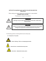
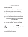
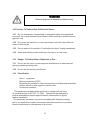
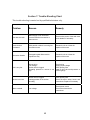
SUCTION SYSTEM
RAIN3 model
Installation & User’s Manual
1
List of Contents
Explanation of the symbols ………………………………………………………
3
Section 1 - Safety information ………………………………………………. 4
z
z
z
Caution: To prevent injury...
Caution: To Reduce Risk Of Electrical Shock...
Danger: To Reduce Risk of Explosion or Fire...
Section 2 - Installation notes ………………………………………………… 6
Section 3 - Operation ………………………………………………………….. 10
Section 4 -
Product information …………………………………………...... 11
z
z
Functional description
Rain3 model
Section 5 - Maintenance ……………………………………………………… 13
z
Cleaning suction inlet filter
z Cleaning suction unit
Section 6 - Disposal …………………………………………………………… 14
Section 7 - Trouble-shooting ………………………………………………… 15
Section 8 - Warranty …………………………………………………………... 16
2
INSTRUCTION WARNING AND CAUTION PLEASE READ BEFORE
OPERATION
While reading your manual, please pay close attention to areas labeled:
WARNING AND CAUTION.
The description of each is found below.
WARNING
Warnings are given where failure to observe instruction could result in
injury to people.
CAUTION
Cautions are found where failure to observe the instruction could result in
damage to the equipment, associated equipment and process.
The following symbols of warning will be found on the pump.
z Explanation of Symbols
Caution / Warning – Refer to accompanying documents
Electrical shock – Attached label at the product
Hot surface – Attached label at the product
3
Section 1: SAFETY INFORMATION
1.10 Caution: To prevent injury...
1.11 Never operate this product if it has a damaged cord or plug. If it is not
working properly, has been dropped, damaged or has fallen into water, please
contact appropriate service center for examination and repair.
1.12 Keep the cord away from heated surfaces. All electrical products
generate heat. To avoid serious burns, NEVER touch suction motor during
or immediately after operation. The temperature of suction motor cab be
reached 120℃.
1.13 Never block any air exhaust valve or place it on a soft surface where the
openings may be blocked. The air exhaust valve is for ventilation of the motor
inside the housing. Keep the air exhaust valve free of lint, dirt and other foreign
objects.
Blocking air exhaust valve can cause the product
to overheat and fire.
1.14
Never drop or insert fingers or any other object into any openings.
1.15
Use only in well ventilated areas. The motor on all product are totally
enclosed fan cooled.
WARNING
Do not operate the pumps in an atmosphere containing
flammable or explosive gases/vapors.
1.16 Be sure to properly identify intake and discharge before using machine.
1.17 Protect Unit from contaminants and moisture.
4
WARNING
Remove plug from air exhaust port before using.
1.20 Caution: To Reduce Risk Of Electrical Shock...
1.21 Do not disassemble. Disassembly or attempted repairs if accomplished
incorrectly can create electrical shock hazard. Refer servicing to qualified service
agencies only.
1.22 Do not use this product in or near area where it can fall or be pulled into
water or other liquids.
1.23
Do not reach for this product if it has fallen into liquid. Unplug immediately.
1.24
Never operate this product outdoors in the rain or in a wet area.
1.30
Danger: To Reduce Risk of Explosion or Fire...
1.31 Do not use this unit in or near explosive atmospheres or where aerosol
(spray) products are being used.
Do not use this product near flames.
1.32
1.40 Classification
-
Class Ⅰ equipment
Ordinary equipment (IPXO)
Equipment not suitable for use in the presence of a flammable anesthetic
mixture with air or with oxygen or nitrous oxide.
Continuous operation.
This equipment has been tested and found to comply with the limits
for medical devices in IEC 601-1-2:1994. These limits are designed to
provide reasonable protection against harmful interference in a typical
medical installation.
This equipment generates, uses and can radiate radio frequency energy
and, if not installed and used in accordance with the instructions, may cause
harmful interference to other devices in the vicinity.
5
However, there is no guarantee that interference will not occur in a
particular installation.
If this equipment does cause harmful interference to other devices, which
can be determined by turning the equipment off and on, the user is
encourage to try to correct the interference by one or more of the following
measures :
- Reorient or relocate the receiving device
- Increase the separation between the equipment.
- Connect the equipment into an outlet on a circuit different from that to which
the other device(s) are connected.
- Consult that manufacturer or field service technician for help.
Section 2: INSTALLATION NOTES
2.10 Environmental Conditions
The Pump is rated for indoor use only. Maximum altitude 2000 meters.
o
o
Operating temperature range 10 C to 40 C. Maximum relative humidity of
o
o
80% for temperatures up to 31 C decreasing to 50% at 40 C. Rated for
+/-10% of supply voltage. Pollution Degree 2, Installation Category II.
2.11 Introduction
This manual has been compiled not only for the care and maintenance of
the suction system now in your possession, but as a helpful reference and
guide to prevent many problems which can occur if used improperly.
2.12 Unpacking
Carefully remove the machine from the shipping case. Preserve all
paperwork for future reference. If damage has occurred from shipment a
claim must be filed with the carrier immediately; preserve the shipping
carton for inspection by the carrier. If you are required to communicate with
your dealer, be sure to include your order numbers for quick identification.
2.13 Mounting
Rubber feet are attached to the product. Rubber feet are excellent
for applications involving a semi-flexible surface such as a bench
top; they help to isolate noise and eliminate creeping. However, the
horizontal position of the motor shaft should be preferred.
2.14 Installation Location
6
The suction system should be located preferably in a clean, dry and well
ventilated area. Please be sure not to block the ventilation ports located on
the motor housing. The unit should be placed where the surrounding
temperature remains between 10oC and 40oC (50oF and 104oF). Always
check to insure the location chose is protected from direct or indirect
moisture contact.
Place suction outlet valve higher position than drainage
to prevent backflow problem
2.15 Hose connection
Please be sure not to be bended any of suction inlet hose and outlet hose. This
can causes loosing vacuum power or damage of suction motor. Also use exhaust
air hose with 38mm diameter hose.
Exhaust air temperature increases significantly and discharge drastically too
hot for most plastic piping. Therefore, metal piping or heat-resistant pipe is
recommended for at least the first five (5) to eight(8) feet (1.5 ~ 2.5 meters)
from the air exhaust valve on the discharge side. In addition, this piping
MUST be guarded and marked “DANGER–HOT–DO NOT TOUCH.”
CAUTION
Do not use hoses such as rubber or PVC hose which are not resistant to
chemicals or disinfectants or insufficient flexibility. Only use PVC flexible
spiral hoses with integrated
spiral or hoses of equivalent material.
7
2.16 Suction Inlet Hose Connection
① Remove the cover of suction inlet and push-in tubing connector in the inlet
hole.
② Connect suction inlet hose (Ø32, spiral hose) at tubing connector and tighten
with electric insulation tape.
2.17 Waste outlet Hose connection
① Always use spiral hose with 19mm interior diameter
② Connect hose to the outlet hole with clockwise
direction
③Please be tighten with hose clip or
electric insulation tape.
④ Always be higher position than drainage to prevent backflow problem.
2.18 Exhaust Air Hose connection
Remove yellow cap from the exhaust air outlet hole.
Connect exhaust air outlet hose to the hole.
8
Always place end of the air outlet hose out of building or window to prevent
noisy problem, hot temperature and bad odor.
Always keep clean water and moisture from end of exhaust air hose
( Be cautious the chance of in-coming water like rain or vapor due to
extension more than 3 meter exhaust air hose.)
2.19 Electrical connection
The mains connection must only be made by well-trained electricians.
To insure safe installation, check local current and voltage. Serious damage may
occur to the motor if it is connected improper voltage.
Electrical Shock Hazard
Disconnect electrical power at the circuit breaker or fuse box before installing this
product. Install the system in a location where it will not come in to contact with
water or other liquids. Install the system in a location protected from the weather.
Electrically ground the system. Failure to follow these instructions can resulting
death, fire or electrical shock.
Section 3:
Operation
Start Up
9
3.10 Check List before start up the system
3.11 Check if there is any foreign material in the cooling fan part of the
motor.
3.12 From the motor side of the system, verify the blower is rotating in the direction
of clockwise. On the system powered by a 3-phase electric power, change the
connection of any two (2) wires to reverse blower rotation.
3.13 Check any abnormal noise or vibration of the suction system. If this happen,
refer to the trouble shooting guide on this manual. After removing causes of
the noise and vibration, re-start the system.
Section 4:
Product information
10
4.10
10 Functional description
⑭
①
⑬
②
⑫
⑪
③
④
⑩
⑨
( Separation unit )
⑤
⑥
⑧
⑦
(Filter part)
1. Vacuum air connection tube
2.Motor Impellor chamber
3. Air / Liquid Separator
4. Separation unit case
5. Waste water outlet
6. Auto by-pass drain tubing
7. Rubber foot
8.Suction Inlet Hole
9. Filter cover
10. Filter housing
11. Electric control unit
12. Power Switch
13. Cooling fan cover
14. Exhaust air outlet
4.11
Rain3 Model
11
¾ Specification
* Main Voltage (VAC)
* Frequency (Hz)
* Electrical Power (Kw)
* Current consumption (A)
* Vacuum regulated (m bar)
* Suction motor rotation speed (rpm)
* No. of treatment units
* Weight (Kg)
* Dimensions (L x W x H)
* Noise level (db)
12
230
50 / 60
0.81 / 0.94
4/5
200
2,900 / 3,720
1–5
33
410 x 520 x 620
65
Section 5:
Maintenance
5.10
Cleaning Suction inlet filter
Cleaning procedures of Filter part
Pull out filter part from machine in counter-clockwise direction of cover.
Clean filter in running water for removing particle or debris.
(Recommending it cleaned at least twice per month for avoiding
reduction of suction power)
③ Re-connect filter.
CAUTION
If the machine installed into the used suction tubing line, old debris
and dirty particle may clogged filter. In case of this, Please clean
filter frequently for some period of time until tubing line is cleaned.
13
5.11
Cleaning Suction Unit
After every treatment – For avoiding bad odor and reducing infection possibility,
Clinic should suck 1 glass of water before the next treatment.
After finishing last treatment of the day – For avoiding bad odor and reducing
infection possibility, Clinic is be sure to clean suction unit
by NON-FOAMING cleaning & disinfectant.
CAUTION
DO NOT use a foaming cleaning & disinfectant agent.
It causes backflow of water to the suction motor and can damage it.
Section 6:
Disposal
CAUTION
This product may be contaminated after using years.
Please make the disposal organization aware of this In order that they can
take the proper safety actions.
Uncontaminated plastic components of the product may be
recycled.
The built-in electric circuit board and other electric components should be disposed
as electric waste.
Other metal components may be disposed of as metallic waste.
If the product is returned to the local dealer, all connections should be closed so
that they are water-tight.
14
Section 7: Trouble-Shooting Chart
This trouble-shooting is carried out by qualified technicians only.
Problem
Reason
Remedy
Unit does not work
Mains supply is not connected
Incorrect electrical connection or
power source
Check mains power, fuses and reset
circuit breaker if necessary
Unusual noise
increased
Solid particle or debris is coming into
the suction motor
Dismantle unit an d clean the
impeller of the motor
Excessive vibration
Damaged impeller Motor and/or
impeller are dirty
Dismantle unit an d clean the
impeller of the motor
Unit is very hot
Wrong wiring
Low voltage
Suction inlet is clogged
Operating pressure or vacuum is too
high
Check wiring
Supply proper voltage
Clean primary filter
Install a relief valve and pressure or
vacuum gauge
Suction is too low
Suction inlet is clogged
Leaking problem in the suction
plumbing
Clean primary filter
Check all suction tubes, hoses. and
connections. Replace if necessary
Motor overload
Low voltage
Check power source
Check wire size and wire
connections
15
.
Warranty
Model : rain3
The warranty starts from the date of our invoice and it’s of 2 years
16