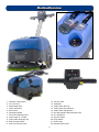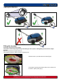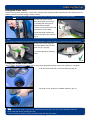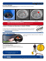
1
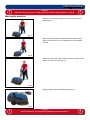
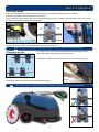
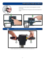
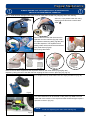
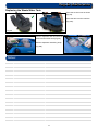
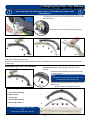
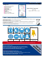
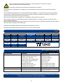
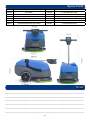
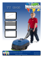
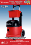
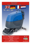
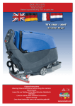
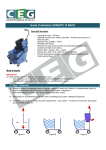
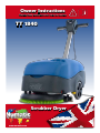
Owner Instructions
Warning! Read instructions before using the machine
TT 1840
Scrubber Dryer
www.numatic.com
MachineOverview
1
12
2
2
11
13
14
15
3
16
4
8
10
7
9
5
6
21
19
20
22
17
1.
2.
3.
4.
5.
6.
7.
8.
9.
10.
11.
18
Operator control panel
On / Off Lever
Waste water tank
Clean water tank
Brush deck
Squeegee blades
Floor-tool retaining knobs
Clean-water on / off tap
Clean-water emptying cap
Rear moving wheels
Floor-tool vacuum hose
12. Vacuum hose
13. Separator
14. Clean-water filler cap
15. Clean-water level indicator
16. Clean-water tank fill point
17. Top tank (waste water) drainage hose
18. On / Off Switch
19. Vacuum Switch
20. Pump Switch
21. Power Light
22. Handle Position lever
2
Quick Set-Up Guide
!
!
Please read before commencing any operation.
After the removal of all the packaging, carefully open and check the contents.
1
Using the handle position lever, move the handle into the
upright position. (Fig 1).
Fig 1
Tip the machine.
(see Page 4)
0L
2
Fit the Brush / Pad (Fig 2).
Fig 2
4
3
Swing the floor-tool carrier from
behind the brush. (Fig 3).
Fig 3
Use the two locking knobs fitted to the floor-tool, secure to the
floor-tool to the floor-tool carrier. (Fig 4).
Fig 4
5
Fill using a hose, bucket or a suitable container. (Fig 5).
Fill the clean-water tank to a Max of 18 litres
(see page 5)
For operation and cleaning controls
(see page 9)
Fig 5
3
Machine Set-Up
Tipping the Machine
0L
5L
0L
Fitting the brushes
Featuring the Nulock brush system.
The brush is fitted simply by pushing and twisting to lock in place, making fitting and removal a simple
process.
Only use manufacturer supplied brushes.
This machine requires a 400mm brush or a 360mm pad.
Slide the brush / pad under the brush deck (Fig 6).
Fig 6
Fit the brush / pad onto the Nulock drive chuck, twist to lock
the brush / pad in place (Fig 7).
Fig 7
Safety gloves are recommended for the changing of used brushes.
4
Machine Set-Up
Fitting the Floor Tool
The floor tool has been designed for quick fitting, allowing easy squeegee blade replacement and a safety knock-off
feature if the floor tool gets snagged, whilst in transit.
Note The lever moves upward and backward motion to lock the floortool in the raised position.
The floor tool carrier can be
raised and locked from moving
by operating the locking lever,
upwards and backwards.
this lever can be found next to the
lower section of the handle.
Unlock and swing the floor-tool
carrier to the side of the machine
(Fig 8).
Fig 8
Note:
It is easier to fit the floor-tool if the weight of the machine is resting on the brush. Ensure the brush is fitted first.
Secure to the carrier using the
two knobs fitted to the floor-tool
carrier (Fig 9) - (Fig 9a).
Do not over tighten the retaining
knobs.
Fig 9
Fig 9a
Filling the clean-water tank
The TT 1840 is equipped with a large 18 litre clean-water tank allowing large areas to be cleaning in a single fill.
To fill the clean-water tank, remove the filler cap (Fig 10).
Fig 10
Fill using a hose, bucket or a suitable container. (Fig 11).
Fig 11
Note.
Great care must be taken to ensure that contaminants (leaves,hair, dirt, etc) are not allowed to enter the
clean-water tank during the filling process.
If using a bucket or similar, ensure it is always clean and free from debris.
5
Machine Set-Up
Fill Level Indicator
Fill the clean water tank to a maximum of 18 litres, including cleaning chemicals if required.
Follow chemical manufacturing guide lines.
Fig 12
Use the fill indicator
(Fig 12).
Fig 13a
Fig 13
Showing the clean-water tank empty
(Fig 13).
Showing the clean-water tank full
(Fig 13a).
When handling and mixing chemicals.
Always ensure that chemical manufacturer’s safety guidelines are followed.
Only use chemicals recommended for use in auto scrubber-dryers.
Control of Substances Hazardous to Health (COSHH)
For best results use a non-foaming type of chemical, dilute to the manufacturer’s specification.
For further guidance on hazardous substances refer to health and safety instructions online.
Visit http://www.hse.gov.uk/ for UK information.
!
Water Flow Adjustment
Located on the left of the machine is the On / Off water tap
(Fig 14 / 15).
Fig 14
Fig 15
Pre-cleaning advice.
Before performing the cleaning operation, place out
appropriate warning signs and sweep or dust-mop the floor
(Fig 16).
Numatic part (629044) Wet Floor sign
(available if required)
!
Fig 16
Important
Do not operate machine unless the Operator Manual has been read and fully understood.
6
!
Machine Set-Up
!
Caution
When moving or lifting the TT 1840, follow the national safety guidelines on lifting.
Moving the machine
!
Transport the machine by tilting back on to the main transit
wheels (Fig 17).
Fig 17
When the top tank (waste water) is full the machine can be
tilted to a maximum of 100 for transporting to dumping area
(Fig 18).
Fig 18
When the bottom tank (clean water) is full the machine can be
tilted to a maximum of 450 (Fig 19).
Fig 19
Weight of empty machine 38.5Kg (85 lbs) fig 20.
Fig 20
!
Caution:
Ensure both tanks are empty before attempting to lift the machine.
7
!
Machine Operation
Pre-scrub mode
The TT-1840 has been designed to cope with a variety of floor types and different levels of soiling.
On heavily soiled floors use a ‘double scrub’ technique.
First pre-scrub the floor with the floor-tool in the raised position (Fig 21), allow the chemical time to work, then scrub
the area a second time with the floor-tool lowered.
Fig 21
Fig 22
Fig 23
To raise the floor-tool, ensure the floor-tool carrier is central to the machine (Fig 22).
Lift the lever near the base of the handle and lock into position (Fig 23).
Note The lever moves upward and backward motion to lock the floortool in the raised position.
Floor tool in use
The clean-water / chemical mix is dispersed via ‘THRU-FEED’ system.
The waste water is then retrieved by the floor-tool
Overlap the scrubbing path by 10cm to ensure an even clean (Fig 24).
Fig 24
If streaking occurs, wipe the floor-tool blades clean (Fig 25).
Note
Fig 25
Care must be taken to reduce speed when cornering or when manoeuvring around obstacles.
8
Setting the cleaning controls
Ensure your TT 1840 machine has been plugged into a suitable
power supply.
Select the desired function using the ON / OFF switches fitted to the
handle.
Vac Switch
Note:
Pump Switch
The Pump Switch will only function when the Brush is in operation.
2
1
1
To start: hold down either trigger and press the yellow start button once
9
Regular Maintenance
!
!
ALWAYS ENSURE THAT THE POWER SUPPLY IS DISCONNECTED,
PRIOR TO ANY MAINTENANCE OPERATION.
The TT 1840 has been designed with ease of use in mind, this included easy stripping-down and cleaning.
After use, empty waste-water tank using
emptying hose and flush-out with clean
water. A
A
Fig 28a
Fig 28
Fig 30
Remove the two hoses and disconnect the
separator from the machine (Fig 28). Undo
the separator restraining strap (Fig 28a) and
lift off the separator. The separator has a
sealing-rubber which should be examined at
every clean-down (Fig 29).
Rinse using clean water.
Fig 31
Fig 30a
Fig 29
Fig 32
Remove the two filters clipped into the separator and flush with clean water (Fig 30)(Fig 30a).
Replace by fitting the rear of the filter first then clipping the front to lock in place (Fig 31) (Fig 32).
Once emptied the top waste-water tank can simply be lifted off. (Fig 33).
Fig 33
The clean-water tank can be drained via the yellow cap fitted to the left
hand side of the machine. The cap has a rubber seal and might require a
spanner to remove. (Fig 34).
NOTE:
Avoid over tightening the clean water draining cap.
Fig 34
10
Regular Maintenance
Replacing the Waste Water Tank
Place the suction hose as shown
(Fig 39).
Place the tank onto the machine
(Fig 39a).
Fig 39
Fig 39a
Refit the separator and reconnect the
vacuum and suction hose (Fig 40).
Refit the separator restraining strap
(Fig 40a).
Fig 40a
Fig 40
Notes:
..............................................................................
..............................................................................
..............................................................................
..............................................................................
..............................................................................
..............................................................................
..............................................................................
..............................................................................
..............................................................................
..............................................................................
..............................................................................
..............................................................................
..............................................................................
..............................................................................
..............................................................................
..............................................................................
11
Changing the Floor-Tool Blades
!
ALWAYS ENSURE THAT THE POWER SUPPLY IS DISCONNECTED PRIOR TO ANY
MAINTENANCE.
!
To change the floor-tool, firstly swing the floor-tool clear of the
machine (Fig 41).
Undo the two floor-tool retaining knobs (Fig 42).
Fig 41
Fig 42
Fig 43
Fig 44
Fig 45
Unscrew the four knobs securing the blade holder (Fig 43).
Remove the blade holder (Fig 44).
Replace the Squeegee blades using (606261) replacement blade set (Fig 45), fitting the blades on to the moulded
location lugs.
Refitting the Floor Tool Blades
Refit the blade holder, retain using the two outer knobs
(Fig 46)
Ensure the slotted blade goes to the front of the
floor-tool (Fig 47).
Note:
The blades are designed to be reversible, thus
extending their useful working life.
Fig 46
Refit the floor-tool using the two central knobs to
the floor-tool.
Refer to Page 5 for fitting instructions.
Fig 47
1. Floor-tool main body
2. Blade carrier
1
3. Rear blade
4. Front blade (slotted)
5. Retaining Knobs x 4
Use Genuine NUMATIC spare parts.
use
Replacement Blade Set (606261)
2
5
3
4
12
About the Machine
Rating Label
1
2
3
4
5
6
7
8
9
10
1
Company Name & Address
Machine Description
Voltage Frequency
Power rating
Max Gradient
Weight (ready to use)
CE Mark
WEEE Logo
Splash Proof Rating
Machine yr/wk Serial number
2
3
Safety Critical Component
4
5
6
Mains lead:
H05VV-F 20m x 1.0 mm2 x 3 core
7
9
8
10
WEEE
(Waste, Electrical and Electronic Equipment)
Scrubber dryer Accessories and packaging should be sorted for environmentally- friendly recycling.
Only for EU countries.
Do not dispose of scrubber-dryer into household waste.
According to the European Directive 2002/96/EC on waste electrical electronic equipment and its
incorporation into national law.
Scrubber-dryers that are no longer suitable for use must be separated, collected and sent for
recovery in an environmentally- friendly manner.
PPE
(Personal protective equipment) that may be required for certain operations).
Ear Protection
Safety Footwear
Head Protection
Safety Gloves
Dust/Allergens
Protection
Eye Protection
Protective
Clothing
Hi-Vis Jacket
Caution
wet floor sign
Note:
A risk assessment should be conducted to determine which PPE should be worn.
Daily
Keep the machine clean
Ensure brushes/ pads/ squeegee/ filters are in good condition
Check for any worn or damaged parts and replace immediately
Drain and rinse dirty water tank after every use
Store machine with brush deck secured in tilted position
Weekly – as daily and –
Check brush or pad and skirt and rinse
Check floor tool blades for wear and wipe clean
Clean separator assembly including filter and check condition of seal
Flush out system with clean water and clean filters
Do not steam clean or pressure wash
13
M Tw
ai in
nt T
en ec
an
ce
Information for Scrubber Dryer
ORIGINAL INSTRUCTIONS
READ MANUAL BEFORE USE
WARNING
Component
Interval
Inspect for
Mains Lead
DAILY
Scuffing, cracks, splits, conductors showing
Brushes
DAILY
Bristle damage, wear, drive collar wear
Squeegee Blade
BEFORE EACH USE
Wear, cracks, splits
Filters
BEFORE EACH USE
Clogging and debris retention
Tanks
AFTER EACH USE
Rinse dirty water tank after use
As with all electrical equipment care and attention must be exercised at all times during its use, in addition
to ensuring that routine and preventative maintenance is carried out periodically in order to ensure its safe
operation.
Failure to carry out maintenance as necessary, including the replacement of parts to the correct standard could render
this equipment unsafe and the manufacturer can accept no responsibility or liability in this respect.
When ordering spare parts always quote the Model Number / Serial Number specified on the Rating Plate.
This appliance is not intended for use by persons (including children) with reduced physical, sensory or mental
capabilities, or lack of experience and knowledge, unless they have been given supervision or instruction concerning
use of the appliance by a person responsible for their safety.
Children should be supervised to ensure that they do not play with the appliance.
This machine is not suitable for picking-up hazardous dust.
Do not use on surfaces having a gradient exceeding that marked on the appliance.
The machine is not to be stored outdoors in wet conditions.
This machine is for indoor use only.
Read the instruction manual before using the appliance.
CAUTION This product meets the requirements of IEC 60335-2-72
NOTES
This machine is also suitable for commercial use, for example in hotels, schools, hospitals, factories, shops and
offices for other than normal housekeeping purposes.
•
•
•
•
•
•
•
•
•
•
•
•
•
•
•
Ensure only competent persons unpack/assemble the machine.
Keep your machine clean.
Keep your brushes in good condition.
Replace any worn or damaged parts immediately.
DO
Regularly examine the power cord for damage, such as cracking or ageing. If damage is found,
replace the cord before further use.
Only replace the power cord with the correct Numatic approved replacement parts.
Ensure that the work area is clear of obstructions and / or people.
Ensure that the working area is well illuminated.
Pre-sweep the area to be cleaned.
•
Use steam cleaners or pressure washers to clean the machine or use in the rain.
•
Attempt machine maintenance or cleaning unless the power plug has been removed from the supply outlet.
•
Allow any inexperienced repairs. Call the experts.
DON’T • Strain cable or try to unplug by pulling on cable.
•
Leave the brush pad on the machine when not in use.
Allow the machine to be used by inexperienced or unauthorised operators or without appropriate training.
Use the machine without the solution tanks properly positioned on the machine, as shown in the instructions.
Expect the machine to provide trouble-free, reliable operation unless maintained correctly.
Lift or pull the machine by any of the operating triggers - Use the main handle.
Remove the handle from the machine except for service and repair.
Use on surfaces having a gradient exceeding that marked on the machine.
14
Only use brushes provided with the appliance or those specified in the instruction manual.
The use of other brushes may impair safety.
WARNING
A full range of brushes and accessories are available for this product.
Only use brushes or pads which are suitable for the correct operation of the machine for the specific task being
performed.
It is essential that this equipment is correctly assembled and operated in accordance with current safety regulations.
When using the equipment always ensure that all necessary precautions are taken to guarantee the safety of the
operator and any other persons who may be affected.
Wear non-slip footwear when scrubbing. Use a respiratory mask in dusty environments.
When cleaning, servicing or maintaining the machine, replacing parts or converting to another function the power
source shall be switched off.
Mains operated machines shall be disconnected by removing the power plug, and battery operated machines shall be
disconnected by switching off the isolating key.
Machines left unattended shall be secured against unintentional movement.
Operators shall be adequately instructed as to the correct use of the machine.
Data
Brush Motor
Vac Motor
Power
Noise
Speed
Brush
Dimensions
400 W
300 W
220-240v 50/60 Hz
115v 50Hz
71 dB(A)
50Hz = 150rpm
400 mm
Width - 520 mm
Length - 880 mm
Height - 1132 mm
Gross Weight
Full
Protection Class
Hand Arm
Vibration
Pad
Net Weight
Cleaning
Range
Water Capacity
360 mm
38.5 Kg
42 m
18 L
56.5 Kg
IPX 4
1.4 +/- 0.06ms²
Fluid Flow
tap @400
Brush / Pad
Pressure
Cleaning Speed
0.35 LPM
27.4 / 26.2
G/ cm2
0-4.2 Kph
TT 1840
Trouble-Shooting
PROBLEM
Poor water pick-up
CAUSE
Waste-water tank full
Clogged / blocked vacuum hose
Loose hose connections
Debris basket filter clogged/blocked
Separator filter clogged / blocked
Poor separator seal
Damaged separator seal
Damaged / split vacuum hose
Damaged floor-tool blades
SOLUTION
No brush / scrub function
No brushes fitted
Check and fit
Little or no water flow
Clean-water tank empty
Clean-water tank filter blocked/ clogged
Fill clean-water tank
Remove and clean
Empty waste-water tank
Remove and clean
Push tight connections
Remove and clean
Remove and clean
Clean and refit
Renew (contact service dept)
Renew (contact service dept)
Renew (contact service dept)
Failure to rectify the problem or in the event of a breakdown contact your Numatic dealer or the
Numatic Technical help line +44 (0)1460 269268
15
Spare Parts
606261
TT 1840 Replacment Blade set
237411
TT 1840 Grit Basket
237466
Skid Plate
237232
TT 1840 Separator Filter
237268
Filler Cap Lid
303985
TT 1840 Filler Cap Assembly
208448
Tank Drain Cap
303961
Clean Tank Filter Assembly (Inside)
208455
M5 Knob (Black)
303997
TT 1840 dump Hose Assembly
208471
Constant Tension Clip (Dump Hose)
213055
TT 1840 Vac Hose
208537
Constant Tension Clip (Vac Hose)
231054
TT 1840 Suction hose
Notes
.................................................................................
.................................................................................
.................................................................................
.................................................................................
.................................................................................
.................................................................................
16
TT 1840 220v ~ 240V ~ 115V
DRW - 13476 (A01) 19/03/2013
17
18
EU Declaration of Conformity
eU declARATiOn
OF
cOnFORmiTY
13
We hereby declare under our sole responsibility that the
following equipment fulfils all the relevant provisions of the
following EU Directives:
Machinery Directive 2006/42/EC
EMC Directive 2004/108/EC
RoHS Directive 2011/65/EU
machine description:
Type: TT, eT series
Manufactured by:
Scrubber dryer
Numatic International Limited
Relevant standards upon which conformity is declared
include:
IEC 60335-1:2010
IEC 60335-2-72:2002 +A1
IEC 62233:2005
EN 55014-1:2006
EN 55014-2:1997+A1
EN 61000-3-2:2006
EN 61000-3-3:1995+A1+A2
A technical construction file for this equipment is retained at
the manufacturer’s address under the authorisation of the
following signatory:
Name:Allyn Boyes
Position: Technical Manager
Signed:
Date: 01 /01/2013
Numatic International Limited,
Chard , Somerset.
TA20 2GB
www.numatic.co.uk
GB
19
TT 1840
ab
L
ffix
ere
H
el
A
Product Serial Number
This machine has been packed
with the following:
Brush / Pad
Floor Tool
Signed
Distributed by:
Numatic International Limited, Chard, Somerset, TA20 2GB, ENGLAND.
Telephone 01460 68600 Fax: 01460 68458 Subject to change without prior notice.
20
www.numatic.co.uk
244163 04/13 (A01)